

Epson BrightLink Pro 1410Wi, BrightLink Pro 1420Wi, BrightLink Pro 1430Wi, BrightLink 475Wi, BrightLink 480i Installation Guide
...Page 1

Installation Guide
Guide d’installation
Page 2
About This Installation Guide
This guide describes how to mount the ultra-short-throw projectors listed below to a wall using the included
Epson® wall mount. It also explains how to install the Control Pad and Touch Unit after wall mount installation.
The following projectors are covered by this guide:
• BrightLink® 475Wi/480i/485Wi/575Wi/585Wi/595Wi and 575Wi+/585Wi+/595Wi+
• BrightLink Pro 1410Wi/1420Wi/1430Wi
• PowerLite® 470/475W/480/485W/570/575W/580/585W
Safety Instructions
For your safety, read all the instructions in this guide before using the wall mount. Incorrect handling that
ignores instructions in this guide could damage the wall mount or could result in personal injury or property
damage. Keep this installation guide on hand for future reference.
Read the safety instructions in the User's Guide for your projector and follow the instructions in this document.
Explanation of Symbols
The warning marks shown below are used throughout this installation guide to prevent personal injury or
property damage. Make sure you understand these warnings when reading this installation guide.
Warning
Caution
This symbol indicates information that, if ignored, could possibly result in personal injury or even death
due to incorrect handling.
This symbol indicates information that, if ignored, could possibly result in personal injury or physical
damage due to incorrect handling.
This symbol indicates related or useful information.
Symbol indicating an action that must not be done
Symbol indicating an action that should be done
Safety Precautions for Installation
Warning
The wall mount is designed specifically for mounting a projector to a wall. If anything other than a
projector is mounted, the weight may result in damage.
If the wall mount falls, it could cause personal injury or property damage.
The installation work (wall mounting) should be performed by specialists who have technical knowledge
and ability. Incomplete or incorrect installation could cause the wall mount to fall and cause personal
injury or property damage.
Follow the instructions in this guide when installing the wall mount.
If the instructions are not followed, the wall mount may fall, resulting in personal injury or property damage.
Follow the instructions in this guide to install and operate the Touch Unit.
If the Touch Unit is not installed and operated properly, the light emitted from the laser could cause injury to
eyesight.
2
Page 3
Warning
Handle the power cord carefully.
Incorrect handling may cause fire or electric shock. Observe the following precautions when handling:
• Do not handle the power plug with wet hands.
• Do not use a power cord that is damaged or modified.
• Do not pull the power cord with too much force when routing the cable through the wall mount.
Do not install the wall mount in a place where it might be subjected to vibration or shock.
Vibration or shock could cause damage to the projector or mounting surface. It could also cause the wall mount or
projector to fall and cause personal injury or property damage.
The installation work should be performed by at least two qualified service personnel. If you need to
loosen any screws during installation, be careful not to drop the wall mount.
If the wall mount or projector falls, it could cause personal injury or property damage.
Install the wall mount so that it can sufficiently support the weight of the projector and wall mount, and
resist any horizontal vibration. Use M10 nuts and bolts and make sure to use appropriate wall anchors for
your wall type.
Nuts and bolts smaller than M10 could cause the wall mount to fall. Epson accepts no responsibility for any
damage or injury caused by lack of wall strength or inadequate installation.
When you mount the projector on the wall with the wall mount, the wall must be strong enough to hold the
projector, the wall mount, as well as the Control Pad and the Touch Unit, if necessary.
This wall mount should be installed on a concrete wall. Confirm the weight of the projector, the wall mount,
the Control Pad, and the Touch Unit before installation, and maintain the strength of the wall. If the wall is
not strong enough, reinforce the wall before installation.
Inspect the wall mount on a regular basis to ensure there are no broken parts or loose screws.
If there are any broken parts, stop using the wall mount immediately. If the wall mount or projector falls, it could
cause personal injury or property damage.
Never modify the wall mount, Control Pad, or Touch Unit.
English
Do not hang on the wall mount or hang a heavy object on the wall mount.
If the projector or wall mount falls, it could cause personal injury or property damage.
Do not use adhesives, lubricants, or oils to install or adjust the wall mount.
If you use adhesives to prevent the screws from loosening or things such as lubricants or oils on the part of the
projector attached to the slide plate, the case may crack and cause the projector to fall, resulting in personal injury
or property damage.
Tighten all screws firmly after adjustment.
Otherwise, the projector or wall mount may fall and cause personal injury or property damage.
Never loosen the bolts and nuts after installation.
Confirm that the screws have not become loose on a regular basis. If you find any loose screws, tighten them
firmly. Otherwise, the projector or wall mount may fall and cause personal injury or property damage.
When performing wiring, make sure the cable does not come into contact with any screws or bolts.
Handling the cable incorrectly may cause fire or electric shock.
Do not apply optical devices such as a magnifying glass or telescope to the laser light diffused from the
Tou ch Unit.
If such optical devices are applied, it could cause personal injury or fire.
Do not look into the Touch Unit’s laser diffusion ports.
This could cause injury to eyesight. Extra care should be taken when children are present.
Do not view the laser light using optical devices such as a magnifying glass within a range of 2.75 inches
(70 mm).
Viewing at close range could cause injury to eyesight.
Connect the Touch Unit to BrightLink 595Wi/595Wi+ and BrightLink Pro 1430Wi models only. Do not
connect it to any other projectors or devices.
3
Page 4
Warning
Do not use the Touch Unit if you are using or near medical equipment such as a pacemaker.
The magnet within the Touch Unit generates electromagnetic interference which could cause medical equipment
to malfunction.
Caution
Do not install the wall mount in a location where the operating temperature for your projector model may
be exceeded. Such an environment may damage the projector.
Install the wall mount in a place free from excessive dust and humidity to prevent the lens or optical
components from becoming dirty.
Do not use excessive force when adjusting the wall mount.
The wall mount may break, resulting in personal injury.
Keep magnetic storage media (for example, magnetic cards or electronic devices such as computers,
digital watches, or cell phones) away from the Touch Unit.
The magnet within the Touch Unit generates electromagnetic interference which could corrupt data or cause the
media or device to malfunction.
Installation Location
• Before installing the projector, verify the power supply wiring for the installation location.
• Install the projector away from other electric devices such as fluorescent lights or air conditioners. Some
kinds of fluorescent lights could interfere with the remote control of the projector.
• Install the projector away from direct sunlight and other bright light sources.
• It is recommended to keep VGA computer cable length less than 65 ft (20 meters) to reduce external
noise.
• Install the projector in a location where the projected image is within reach.
• The projector must be installed in one of the following locations in order for the Touch Unit to function
properly:
• Mounted on a wall or suspended from the ceiling with images projected from in front of the screen.
• Mounted vertically on a table with images projected from the front of the table. If using this
installation method, you need the optional interactive table mount (ELPMB29) and attachment plate
(ELPPT05).
• When powering the Control Pad using batteries, verify that the installation location meets the following
conditions:
• Install the Control Pad on the same surface as the projection screen. If the projection screen and the
Control Pad installation point are uneven, install the Control Pad approximately 8 in (20 cm) from the
edge of the screen.
• Make sure there are no obstacles between the Control Pad and the projector (not including the Touch
Unit).
• Use the optional Remote Control Cable Set (model ELPKC28, part number V12H005C28) to supply power
to the Control Pad in the following situations:
• The required conditions above are not met.
• The projection screen and the Control Pad installation point are uneven and the difference in height is
more than 2 inches (5 cm).
• The projector is placed on a table and projecting to the screen.
• Multiple projectors are being used.
4
Page 5

• Before installing the Touch Unit, verify that the installation location meets the following conditions:
• The Touch Unit can be secured to the surface with magnets or screws.
• The surface is flat, smooth, and unwarped with no more than 0.2 inches (5 mm) of unevenness in any
direction on the screen surface.
0.2 in. (5 mm)
• When installing on a whiteboard, install the Touch Unit within the frame of the whiteboard.
English
Correct position Incorrect position
Make sure there are no obstacles, such as cables, or protruding objects such as whiteboard trays, pen
holders, or thick frames in the shaded areas in the following figure. The Touch Unit will not operate
correctly if anything is obstructing the infrared signal.
4.0 in. (100 mm)4.0 in. (100 mm)
0.8 in. (20 mm)
5
Page 6

1 Package Contents
s 8
2 Specifications
3 Connecting Devices
4 Positioning the Projector
1. Installation worksheet for projecting on a pre-installed wall-mounted board
2. Installation worksheet for projecting on a plain wall
3. Diagonal image size and mounting position
4. Distance from projection surface to wall plate
5. Installation measurement tables
6. Installation Measurements in Inches for WXGA Projectors
7. Installation Measurements in Inches for XGA Projectors
8. Installation Measurements in Millimeters for WXGA Projectors
9. nstallation Measurements in Millimeters for XGA Projectors
5 Installing the Projector
1. Disassemble the parts
s 10
s 14
s 16
s 30
2. Assemble the parts
3. Install the wall plate on the wall
4. Determine the projection distance and pull out the slider
5. Route the cables through the wall mount arm
6. Attach the mount arm to the wall plate
7. Adjust the vertical slide position of the arm
8. Attach the projector to the wall mount
9. Connect the power cord and other cables to the projector
6
Page 7
6 Adjusting the Image
1. Turn on the projector
2. Display the test pattern
s 41
3. Change the aspect ratio if necessary
4. Adjust the focus
5. Use the adjustment knob on the left side to adjust the horizontal roll
6. Use the adjustment knob on the right side to adjust the horizontal rotation
7. Use the adjustment knob on the top to adjust the vertical tilt
8. Adjust the horizontal slide
9. Adjust the forward/backward slide
10. Adjust the vertical slide
11. Turn off the display of the test pattern
7 Attaching the Covers
1. Attach the wall plate cover and end cap
2. Attach the cable cover to the projector
8 Installing the Touch Unit
1. Turn on the projector
2. Display the installation pattern
English
s 47
s 49
3. Remove the markers
4. Determine the installation position for the Touch Unit
5. Install the Touch Unit
6. Connect the cable
7. Adjust the angle
8. Store the markers and attach labels
9. Attach cover
9 Installing the Control Pad
1. Remove the cable cover
2. Attach the Control Pad
3. Install the batteries
4. Connect the projector cables to the Control Pad
5. Attach the port protection stickers
6. Attach the cable cover
10 Appendix
s 62
s 66
1. Using the Easy Interactive Function
2. Attaching a Security Cable
7
Page 8
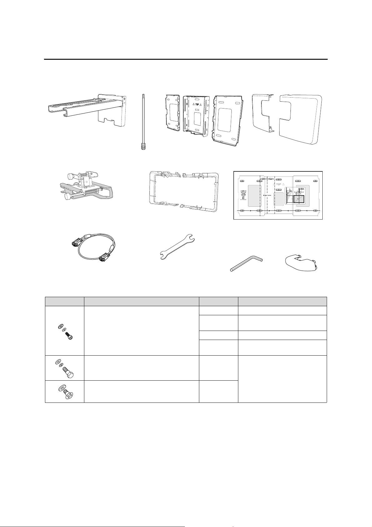
1 Package Contents
Wall Mount
Wall mount
Hexagonal shaft
3-axis adjustment unit and slide
plate (attached when shipped)
VGA computer cable (may be included
with projector or wall mount)
Shape Name Quantity Application
M4 × 12 mm hexagon socket head cap bolt with
washer/spring washer
M6 × 20 mm hexagon shoulder bolt with washer/
spring washer
Wall plate cover extender
Open-ended wrench
13 mm (for M8 and M6) ×
6 mm (for hexagonal
Wall plate
(for installing the wall plate)
Hexagon wrench (for M4)
shaft)
6 For wall plate assembly
4 For 3-axis adjustment unit/wall mount
installation
4 For slide plate/projector installation
2 For slide plate/3-axis adjustment unit
installation (secured when shipped)
1 For wall mount/wall plate installation
Wall plate cover
Template sheet
End cap
M6 × 20 mm cross recessed head shoulder screw
with plastic washer
3
• Use the bolts or screws supplied with the wall mount to install it as directed in this guide. Do not
substitute these bolts with any other types.
• You need to use commercially available M10 × 60 mm anchors (at least 3) to attach the wall plate to the
wall.
• Gather the tools and parts you need before you begin installation, including a #3 cross-head screwdriver.
8
Page 9

Touch Unit
The following parts are packaged with your projector and are necessary when attaching the Touch Unit. When
installing the Touch Unit on a non-magnetic surface, you will also need three M4 screws.
English
Touc h Unit and marke rs
(markers are inside the unit)
Touch Unit connection cable
Label (×4)
Tap e (a ppr ox. 2.4 inc hes
[6 cm]) for securing the
markers (×12)
Spacer for screw hole (×3)
Infrared deflector (approx.
11.2 inches [28.5 cm]) (×8)
Control Pad
The following parts are packaged with your projector and are necessary when attaching the Control Pad.
When installing the Control Pad on a wall, you will also need four M4 × 20 mm screws.
Control Pad
AA size batteries (× 2) Port protection
Rubber feet
stickers
9
Page 10

2Specifications
Item Specification Additional information Reference
Page
Wall mount weight (including the
3-axis adjustment unit, slide plate,
wall plate, wall plate cover, wall
plate cover extender, and end cap)
Approx. 18.5 lb
(8.4 kg)
Wall mount: 6.6 lb (3.0 kg)
3-axis adjustment unit: 2.6 lb (1.2 kg)
Slide plate: 1.8 lb (0.8 kg)
Wall plate: 6.0 lb (2.7 kg)
Wall plate cover and end cap: 0.9 lb (0.4 kg)
Wall plate cover extender: 0.6 lb (0.3 kg)
Maximum load capacity 15.4 lb (7 kg) — —
Vertical slide adjustment range ± 1.5 in. (38 mm) — Refer to the
Horizontal slide adjustment range ± 1.8 in. (45 mm) — Refer to the
Forward/backward slide
adjustment range
0 to 14.2 in.
(360 mm)
Arm slide adjustment range: 0 to 10.7 in. (273 mm)
Adjustment from 3-axis adjustment unit installation
position: 3.4 in. (87 mm)
Horizontal roll adjustment range ± 3° Fine adjustments possible with adjustment knob
Horizontal rotation adjustment
± 8° Fine adjustments possible with adjustment knob
range
Vertical tilt adjustment range ± 3° Fine adjustments possible with adjustment knob
—
illustration
below
illustration on
page 11
Refer to the
illustration on
page 11
s p. 44
s p. 44
s p. 45
Wall plate
The wall plate is in three pieces when shipped. Use the included M4 × 12 mm bolts (×6) to attach the separate
pieces together before mounting the projector. See page 31 for instructions.
5.1 in.
(130 mm)
1.0 in.
(25 mm)
3.2 in.
(80 mm)
1.2 in.
(30.6 mm)
4.2 in.
(106.5 mm)
19.5 in. (496 mm)
3.1 in.
(79 mm)
2.4 in.
(60 mm)
4.6 in. (117 mm)
8.8 in. (223 mm)
1.3 in.
(33 mm)
9.7 in. (246 mm)
8.7 in. (222 mm)
8.4 in. (213 mm)
6.3 in. (160 mm)
Vertical slide adjustment range
1.5 in. (38 mm)
1.5 in. (38 mm)
10
Page 11
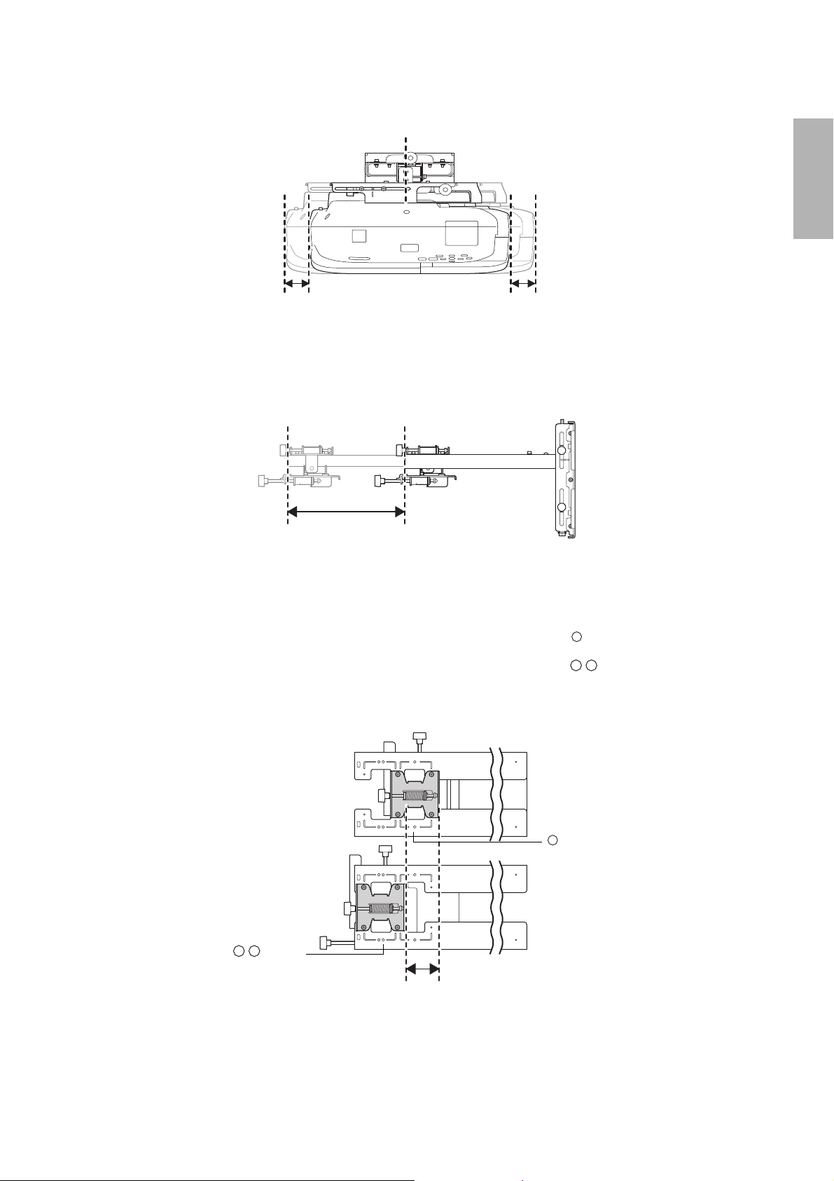
Horizontal slide adjustment range
English
1.8 in. (45 mm)
1.8 in. (45 mm)
Forward/backward slide adjustment range
Arm slide adjustment range
10.7 in. (273 mm)
Adjustment from 3-axis adjustment unit installation position
By changing the installation position of the 3-axis adjustment unit to the front or back, you can adjust the
installation position of the projector.
When the screen size is less than 75 inches, install it at the position marked with a stamp on the mount arm.
When the screen size is 75 inches or more, install it at the position marked with a stamp on the mount
arm.
To see these stamps, you need to remove the two top screws and slide out the arm extension.
Stamp
Stamp
3.4 in.
(87 mm)
11
Page 12

Touch Unit
External dimensions and weight
The Touch Unit weighs approximately 16 ounces (450 g).
3.7 in. (95 mm)
8.3 in. (210 mm)
2.0 in.
(51 mm)
Attached labels
The Touch Unit is a Class 1 laser product that conforms to the JIS C 6802:2011 standard. There are warning
labels affixed to the Touch Unit to indicate that it is a Class 1 laser product. The labels contain the following
information:
• Invisible laser radiation
• Do not view the beam directly with optical instruments
• Class 1 laser product
Laser diffusion port
The laser beam is diffused from the laser diffusion ports on the back of the Touch Unit.
12
Laser diffusion ports
Page 13
Control Pad
External dimensions and weight
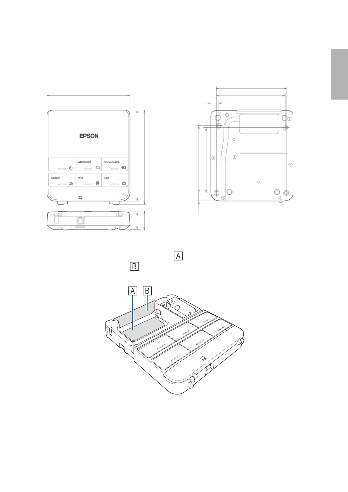
The Control Pad weighs approximately 8.5 ounces (240 g).
5.4 in (135.9 mm)
Cable routing holes
4.4 in (111 mm)
0.4 in
(11.5 mm)
5.9 in (149 mm)
6.0 in (153.5 mm)
4.2 in (107 mm)
4.0 in (104 mm)
0,6 in
1.2 in
1.1 in
(29 mm)
(30.9 mm)
(15.47 mm)
4.3 in (109 mm)
0.1 in (3.5 mm)
English
When routing cables through a wall, use the position ( ) in the following figure as the cable routing hole.
Otherwise, remove the cable cover ( ) and route the cables through the opening. Route the printer cable
along the groove on the back of the Control Pad.
13
Page 14

3Connecting Devices
Make sure you have the power cord, computer cable, and other parts at the location where the wall mount is
to be installed.
Make sure you also have all necessary cables for the Touch Unit and other devices, such as a document camera
or microphone, that you will connect to the projector. Your projector’s connection panel may differ slightly
from the displayed model. For details, refer to the online User’s Guide for your projector.
Connection Example
External speakers
Audio cable
(not included)
Microphone
Document camera
(Epson DC-06)
Touch Unit connection
cable
LAN device
Tou ch Unit
LAN cable
(not included)
Computer cable
(for computer video
output)
Computer
USB cable (for Easy
Interactive Function)
Dedicated USB cable
(supplied with document camera)
For Interactive Use
When interacting with a computer, you need a USB cable. However, when using the projector's
built-in toolbar, you do not need a USB cable.
14
Page 15

Connecting the Control Pad
The Control Pad is included with the BrightLink Pro 1410Wi/1420Wi/1430Wi projectors. It provides a
convenient alternative to the remote control for turning on the projector, changing the source, and selecting
whiteboard mode. You can also use the control pad to capture, print, and save your projected images.
You must install the control pad on the same surface as the projector, within the range specified in the
installation instructions. You can use the included batteries to power the control pad, or the optional remote
control cable set (model ELPKC28, part number V12H005C28).
See ”Installing the Control Pad” on page 62 for instructions.
English
15
Page 16
4 Positioning the Projector
BrightLink Pro 1410Wi/1420Wi/1430Wi, BrightLink 475W/485W, BrightLink 575Wi/585Wi/595Wi, BrightLink
575Wi+/585Wi+/595Wi+ and PowerLite 475W/485W/575W/585W can project up to 100 inches diagonally for
a WXGA image or 88 inches diagonally for an XGA image. The BrightLink 480i and PowerLite 470/480/570/580
can project up to 93 inches diagonally for an XGA image.
You can project onto a pre-installed whiteboard or directly onto a plain wall. When installing the Touch Unit,
install it on the screen that is being used for projection; you need at least 4.7 inches (120 mm) between the top
edge of the projected image and the top edge of the screen. The height of the included wall mount
determines the maximum image size and how high the image appears on the wall or whiteboard. The
distance of the projector from the wall (once it is mounted on the adjustable arm of the wall mount) also
affects image size and position.
If you are planning to project on a whiteboard, the image may not fill the entire board, depending on the
aspect ratio. If you match the image height to the board’s height, gaps may appear on the sides of the board.
Use the following worksheets to determine the proper location of the wall plate on the wall. If you are
projecting onto a pre-installed whiteboard, use the worksheet on page 17. If you are projecting on a plain
wall, use the worksheet on page 18.
When installing on a whiteboard, make sure to leave the following gaps around the
edge of the board:
❏ From the top of the projected image to the bottom of the Touch Unit: 1 inch
(25 mm)
❏ From the edges of the projected image to the edges of the board: at least 4 inches
(100 mm) left and right
❏ From the bottom of the projected image to the bottom of the board: 0.8 inches
(20 mm)
If there are obstacles such as cables, whiteboard trays, pen holders, or frames within
the areas listed above, the Touch Unit will not operate properly.
16
Page 17
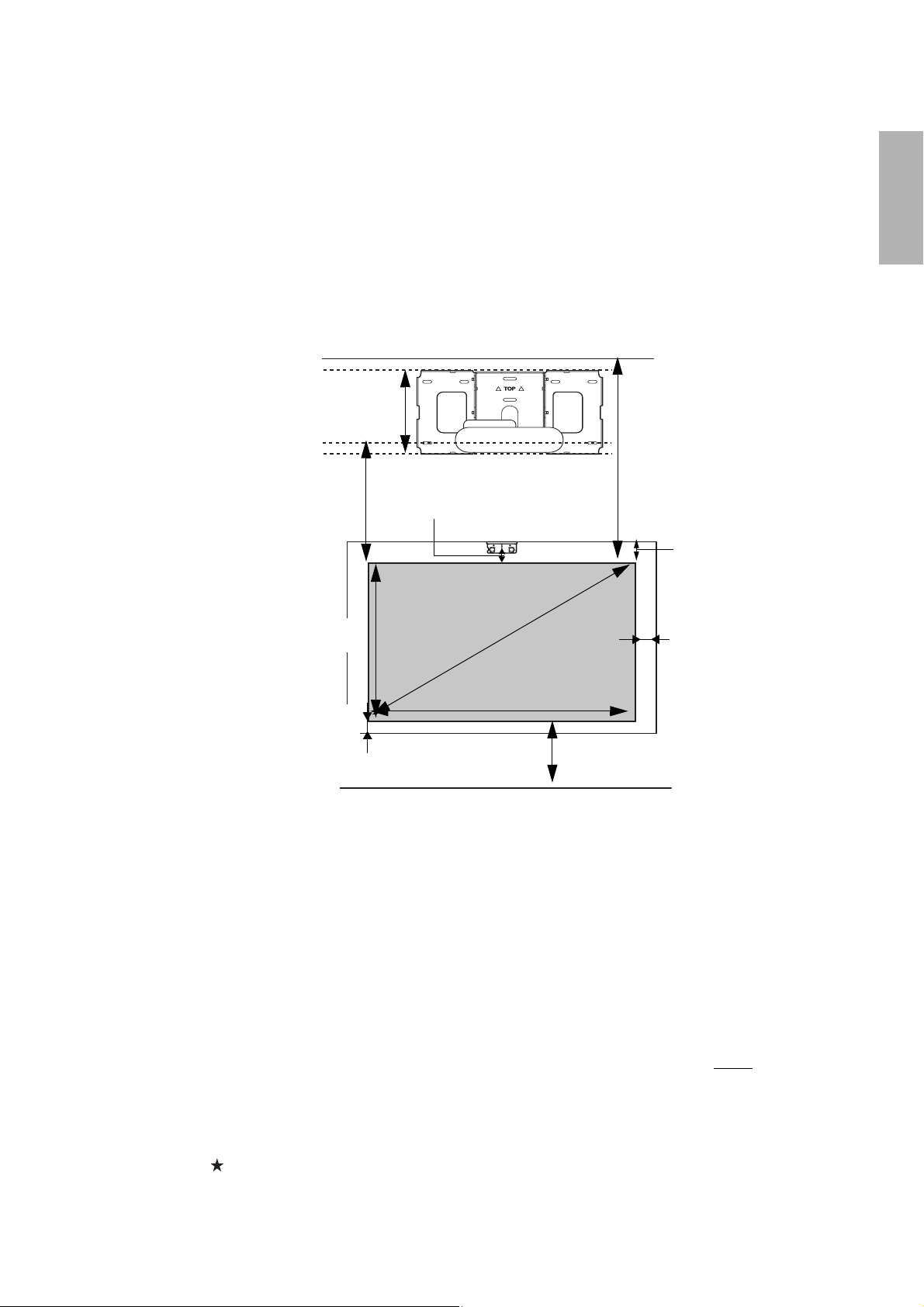
Installation worksheet for projecting on a pre-installed wall-mounted board
1. Measure the ceiling height (distance from the floor to the ceiling). _____
2. Measure the height of the board’s image area (h). _____ (h)
3. Measure the width of the board’s image area (w). _____ (w)
4. Measure the distance from the floor to the bottom of the board’s image area (f). _____ (f)
5. Measure the distance from the ceiling to the top of the board’s image area (d). _____ (d)
6. Measure the thickness of the board (distance from the projection surface to the wall) (x). _____ (x)
English
10 in. (254 mm)—height of
wall plate plus cover
Required distance from top
of image area to bottom
holes of wall plate (c)
Height of
image area (h)
0.8 in. (20 mm)—
distance from bottom
of image area to
bottom of board
1.0 in. (25 mm)—distance
from top of image area to
bottom of Touch Unit
Diagonal size of
image area (S)
Width of image area (w)
Distance from floor to
bottom of image area (f)
Distance from ceiling to
top of image area (d)
7. Determine the aspect ratio of the board or of the images that will be projected. For
new computers or laptops, this will most likely be WXGA (16:10). For older equipment,
this will most likely be XGA (4:3). You may need to consult your IT department for this
information.
___ 4:3 XGA ___ 16:10 WXGA ___ 16:9 Widescreen
4.7 in. (119 mm)—
distance from top of
image area to top of
board (Touch Unit
only)
4.0 in. (100 mm)—
distance from edge of
image area to edge of
board
8. Using the tables on pages 21 to 28 for your aspect ratio and desired image height (h),
find the required distance between the top of the image area and the bottom holes of
the wall plate (c).
9. Determine the position for your projector installation by adding the values for (f), (h),
and (c), plus an additional 10 inches for the height of the wall plate plus the cover.
If the ceiling height of your room (as noted in step 1) does not meet the minimum
ceiling height required for your board, you may need to select a smaller image size or
move the board to a lower position on the wall.
10. After confirming your image size, use tape or a pencil to mark the distance (c) from the
top of the image area on the board to the bottom holes of the wall plate.
11. Align the line (horizontal) on the template sheet with the (c) mark, then align the
center line on the template sheet with the center of the image area. Follow the
instructions on page 30 to install the projector.
17
_____ (c)
_____ (f)
_____ (h)
_____ (c)
+10
inches
_____ total
Page 18

Installation worksheet for projecting on a plain wall
1. Measure the ceiling height (distance from the floor to the ceiling). _____
2. Determine the desired aspect ratio of the image. For new computers or laptops, this
will most likely be WXGA (16:10). For older equipment, this will most likely be XGA (4:3).
You may need to consult your IT department for this information.
___ 4:3 XGA ___ 16:10 WXGA ___ 16:9 Widescreen
3. Using the tables on pages 21 to 25 for your aspect ratio, select the largest image size
available for your ceiling height.
Image height (h)
Image width (w)
_____ (h)
_____ (w)
4. Determine the desired distance from the floor to the bottom of the image area (f).
_____ (f)
The recommended minimum distance is 30 inches. Images appearing less than 28
inches from the floor may be obstructed for some viewers.
5. Find the top of the projected image area by adding distances (f) and (h). _____
6. Use the tables on pages 21 to 28 to determine the required distance from the top of the
image area to the bottom holes of the wall plate (c). _____ (c)
7. Add:
Required distance from top of image area to bottom holes of wall plate (c)
Height of image area (h)
Distance from floor to bottom of image area (f)
Height of wall plate plus cover
If the total exceeds the ceiling height, you will need to reduce the image size or reduce
_____ (c)
_____ (h)
_____ (f)
+10
_____ total
the distance from the floor to the bottom of the image area.
10 in. (254 mm)—height of
wall plate plus cover
Required distance from top of
image area to bottom holes of
wall plate (c)
1 in. (25 mm)—distance
from top of image area to
bottom of Touch Unit
Distance from ceiling
to top of image area (d)
inches
Ceiling height
Height of
image area (h)
Diagonal size of
image area (S)
Width of image area (w)
Distance from floor to
bottom of image area (f)
18
Page 19
8. After confirming your image size, use tape or a pencil to mark the distance (c) from the
top of the image area on the board to the bottom holes of the wall plate.
9. Align the line (horizontal) on the template sheet with the (c) mark, then align the
center line on the template sheet with the center of the image area. Follow the
instructions on page 30 to install the projector.
The tables on the following pages provide installation information for all supported image sizes. The
minimum ceiling height is based on an image 30 inches from the floor; if the image is lower, the minimum
ceiling height is reduced by the corresponding measurement.
Use the worksheets, the illustrations, and the information in the tables on the following pages to determine
the projection distance and placement of the wall plate. The recommended range for projection distance (a)
as shown on the following pages is 2.5 to 12.2 inches (62 to 311 mm).
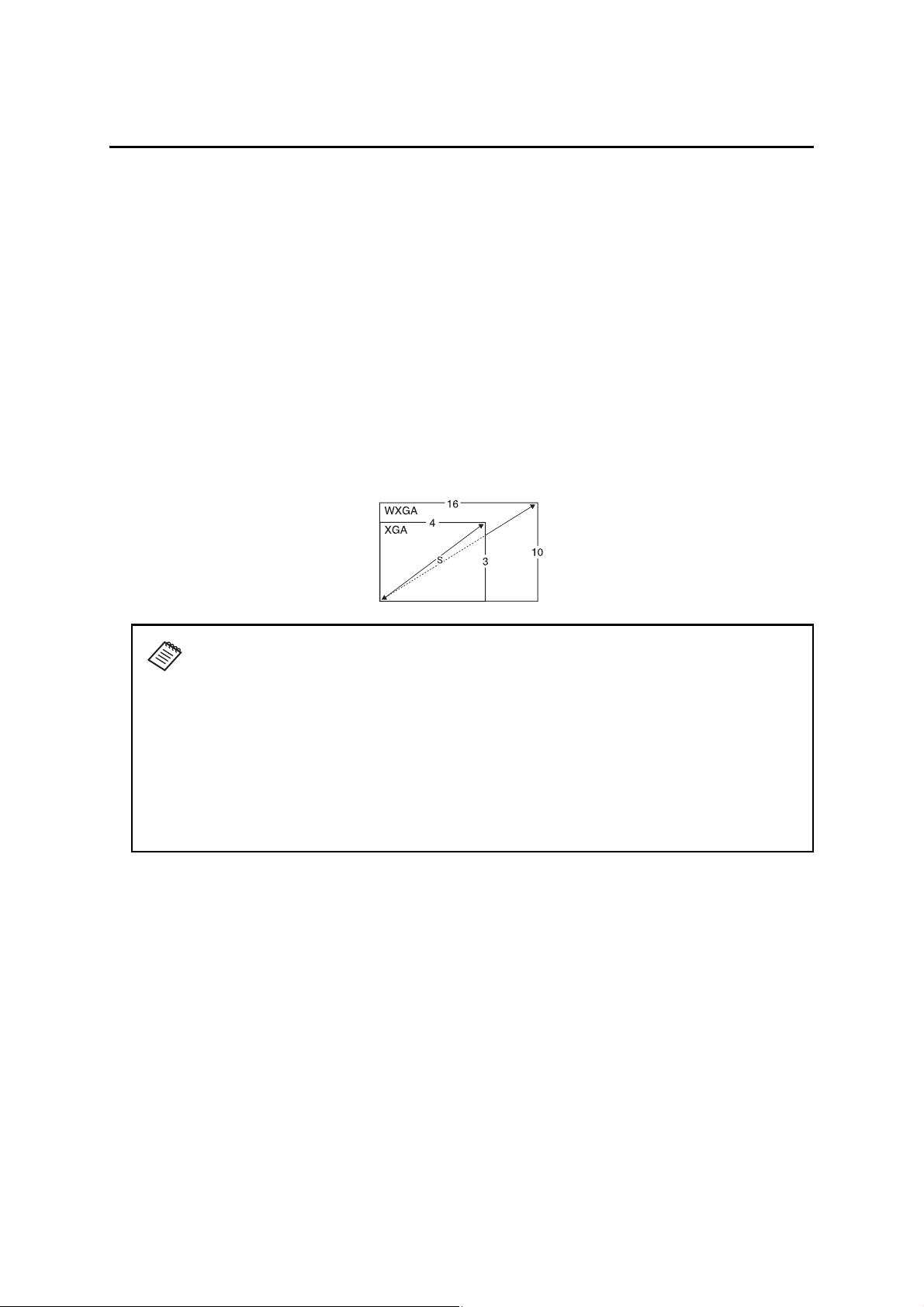
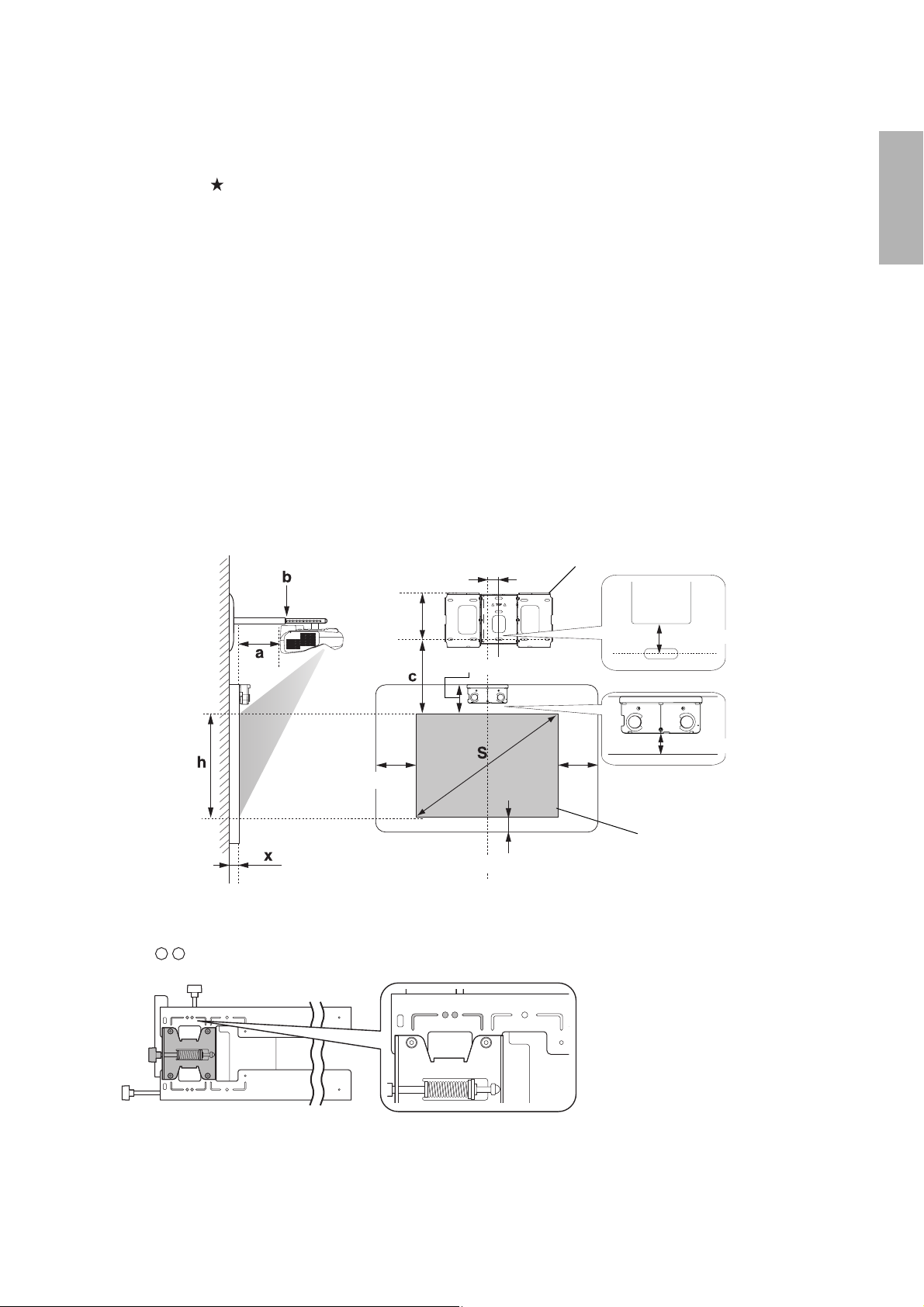
Diagonal image size and mounting position
The numbers on the slider measure (b) are the same as the projection distance (a) when the diagonal image
size (S) is 75 inches or more. Because the installation position of the projector changes when (S) is less than 75
inches, the numbers for (a) and (b) differ.
Offset value for the position of the
center of the screen and the center of
the wall plate
2.8 in. (70.5 mm)
Wall plate
English
8.6 in.
Height of
projected
image
(218 mm)
4.0 in. (100 mm)
Distance from wall to
projection surface
4.7 in. (120 mm)
0.8 in. (20 mm)
1.2 in. (30.6 mm)
1 in. (25 mm)
Projection
surface
In order to see the stamp and the numbers on the slider scale, you need to slide out the arm extension.
When the diagonal image size is 75 inches or more, mount the 3-axis adjustment unit at the position marked
with a stamp.
19
Page 20

When the diagonal image size is less than 75 inches, mount the 3-axis adjustment unit at the position marked
with a stamp.
Distance from projection surface to wall plate
The distance (c) from the projection surface to the bottom mounting holes on the wall plate is the number
given when the vertical slide is set to the base position, as shown below.
Match the notch on the wall mount to the position of the stamp on the wall plate.
Base position
Stamp on plate
Notch on mount arm
Installation measurement tables
Use the following table to determine which installation measurement table to use for your projector.
Projector model Maximum image
size (diagonal)
BrightLink Pro 1410Wi/1420Wi/1430Wi
BrightLink 475W/485W/575Wi/585Wi/595Wi
100 WXGA
BrightLink 575Wi+/585Wi+/595Wi+
PowerLite 475W/485W/575W/585W
BrightLink 480i
93 XGA
PowerLite 470/480/570/580
The measurements may differ depending on the location where you place the
projector.
When projecting in Tele, the quality of the projected images may decrease.
When using a WXGA projector to project images at a 4:3 aspect ratio, the images are
resized automatically and the quality of the projected images may decrease.
When the wall plate cover extender is installed, the minimum diagonal image size is
increased to: WXGA 67” (16:10), 65” (16:9), 59” (4:3); XGA 62” (4:3), 57” (16:9),
59”(16:10).
Installation
measurement table
20
Page 21
Distance
from top of
scale
Slider
holes (c)
image to
wall plate
(b)
mark
English
Min.
projection
Image
height
width
Image
Min.
ceiling
Distance
from top of
scale
Slider
Min.
projection
Image
height
(a)
distance
(h)
(w)
height*
image to
wall plate
(b)
mark
(a)
distance
(h)
holes (c)
16:10 WXGA 4:3 XGA 16:9 Widescreen
Image
Min.
Distance
Slider
Min.
Image
Image
Min.
(w)
width
ceiling
height*
image to
from top of
scale
mark
distance
projection
(h)
height
(w)
width
ceiling
height*
holes (c)
wall plate
(b)
(a)
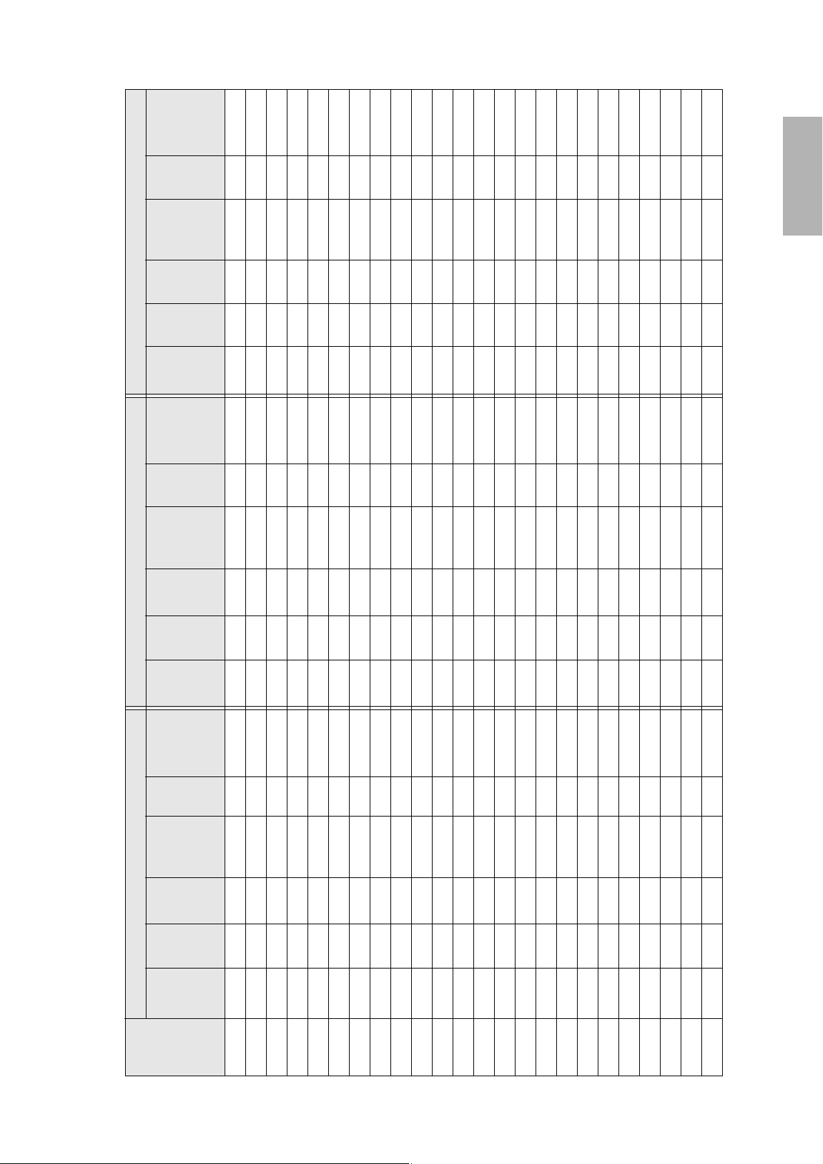
78.7 42.4 31.8 2.5 5.9 6.9 — — — — — —
79.4 43.2 32.4 2.7 6.1 7.0 — — — — — —
80.1 44.0 33.0 3.0 6.4 7.1 — — — — — —
80.8 44.8 33.6 3.3 6.7 7.2 — — — — — —
81.5 45.6 34.2 3.6 7.0 7.3 — — — — — —
82.3 46.4 34.8 3.8 7.3 7.5 — — — — — —
83.0 47.2 35.4 4.1 7.6 7.6 77.5 51.4 28.9 2.6 6.0 8.5
78.7 50.9 31.8 2.5 5.9 6.9 83.7 48.0 36.0 4.4 7.8 7.7 78.1 52.3 29.4 2.9 6.3 8.7
79.3 51.7 32.3 2.7 6.1 7.0 84.4 48.8 36.6 4.7 8.1 7.8 78.7 53.2 29.9 3.1 6.5 8.8
79.9 52.6 32.9 3.0 6.4 7.1 85.1 49.6 37.2 5.0 8.4 7.9 79.3 54.0 30.4 3.4 6.8 8.9
80.6 53.4 33.4 3.2 6.6 7.2 85.8 50.4 37.8 5.2 8.7 8.0 80.0 54.9 30.9 3.6 7.0 9.1
81.2 54.3 33.9 3.4 6.9 7.3 86.6 51.2 38.4 5.5 8.9 8.2 80.6 55.8 31.4 3.9 7.3 9.2
81.8 55.1 34.4 3.7 7.1 7.4 87.3 52.0 39.0 5.8 9.2 8.3 81.2 56.7 31.9 4.1 7.6 9.3
82.5 56.0 35.0 3.9 7.4 7.5 88.0 52.8 39.6 6.1 9.5 8.4 81.8 57.5 32.4 4.4 7.8 9.5
83.1 56.8 35.5 4.2 7.6 7.6 88.7 53.6 40.2 6.3 9.8 8.5 82.5 58.4 32.9 4.6 8.0 9.6
83.7 57.7 36.0 4.4 7.8 7.7 89.4 54.4 40.8 6.6 10.0 8.6 83.1 59.3 33.3 4.9 8.3 9.7
84.4 58.5 36.6 4.7 8.1 7.8 90.2 55.2 41.4 6.9 10.3 8.8 83.7 60.1 33.8 5.1 8.5 9.9
85.0 59.4 37.1 4.9 8.3 7.9 90.9 56.0 42.0 7.2 10.6 8.9 84.3 61.0 34.3 5.4 8.8 10.0
85.6 60.2 37.6 5.1 8.6 8.0 91.6 56.8 42.6 7.4 10.9 9.0 85.0 61.9 34.8 5.6 9.1 10.2
86.3 61.1 38.2 5.4 8.8 8.1 92.3 57.6 43.2 7.7 11.1 9.1 85.6 62.8 35.3 5.9 9.3 10.3
86.9 61.9 38.7 5.6 9.1 8.2 93.0 58.4 43.8 8.0 11.4 9.2 86.2 63.6 35.8 6.1 9.6 10.4
87.5 62.8 39.2 5.9 9.3 8.3 93.8 59.2 44.4 8.3 11.7 9.4 86.8 64.5 36.3 6.4 9.8 10.6
88.2 63.6 39.7 6.1 6.1 8.4 94.5 60.0 45.0 8.5 8.5 9.5 87.5 65.4 36.8 6.6 6.6 10.7
88.8 64.4 40.3 6.4 6.4 8.5 95.2 60.8 45.6 8.8 8.8 9.6 88.1 66.2 37.3 6.9 6.9 10.8
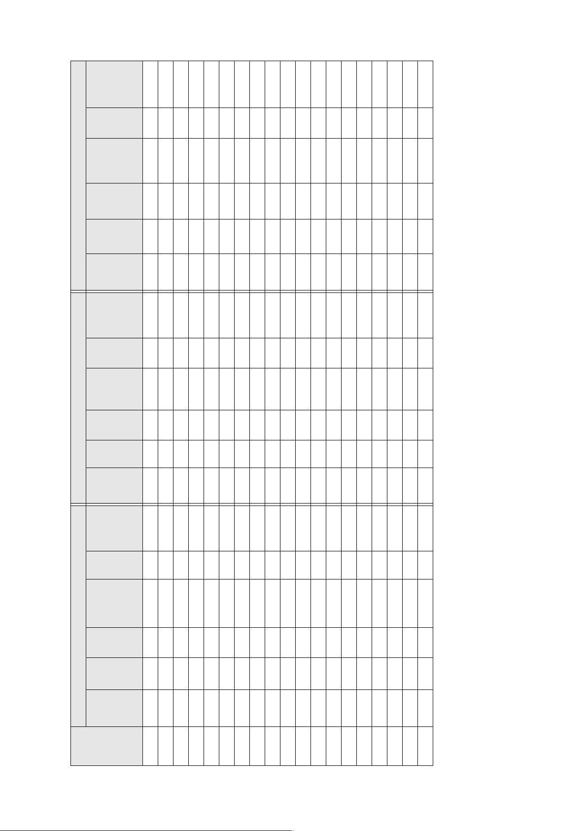
Installation Measurements in Inches for WXGA Projectors
image
Diagonal
(S)
size
54” ———— ——
53” ———— ——
55” ———— ——
56” ———— ——
57” ———— ——
58” ———— ——
59” ———— ——
60”
61”
62”
63”
64”
65”
66”
67”
68”
69”
70”
71”
72”
73”
74”
75”
76”
21
Page 22
Distance
Slider
from top of
scale
image to
wall plate
(b)
mark
holes (c)
Min.
Image
Image
Min.
Distance
Slider
Min.
Image
projection
height
width
ceiling
from top of
scale
projection
height
(a)
distance
(h)
(w)
height*
image to
wall plate
(b)
mark
(a)
distance
(h)
holes (c)
9.1 9.1 12.0
9.4 9.4 12.2
9.6 9.6 12.3
9.9 9.9 12.5
10.2 10.2 12.6
10.4 10.4 12.7
10.7 10.7 12.9
41.7
42.2
42.7
43.1
43.6
44.1
44.6
16:10 WXGA 4:3 XGA 16:9 Widescreen
width
Image
Min.
ceiling
Distance
from top of
scale
Slider
Min.
projection
Image
height
width
Image
Min.
ceiling
(w)
height*
image to
wall plate
(b)
mark
(a)
distance
(h)
(w)
height*
holes (c)
90.1 66.1 41.3 6.9 6.9 8.8 96.6 62.4 46.8 9.4 9.4 9.8 89.3 68.0 38.2 7.4 7.4 11.1
90.7 67.0 41.9 7.1 7.1 8.9 97.4 63.2 47.4 9.7 9.7 10.0 90.0 68.9 38.7 7.6 7.6 11.2
91.4 67.8 42.4 7.3 7.3 9.0 98.1 64.0 48.0 9.9 9.9 10.1 90.6 69.7 39.2 7.9 7.9 11.4
92.0 68.7 42.9 7.6 7.6 9.1 98.8 64.8 48.6 10.2 10.2 10.2 91.2 70.6 39.7 8.1 8.1 11.5
92.6 69.5 43.5 7.8 7.8 9.2 99.5 65.6 49.2 10.5 10.5 10.3 91.8 71.5 40.2 8.4 8.4 11.6
93.3 70.4 44.0 8.1 8.1 9.3 100.2 66.4 49.8 10.8 10.8 10.4 92.5 72.3 40.7 8.6 8.6 11.8
93.9 71.2 44.5 8.3 8.3 9.4 100.9 67.2 50.4 11.0 11.0 10.5 93.1 73.2 41.2 8.9 8.9 11.9
94.5 72.1 45.0 8.6 8.6 9.5 101.7 68.0 51.0 11.3 11.3 10.7 93.7 74.1
95.2 72.9 45.6 8.8 8.8 9.6 102.4 68.8 51.6 11.6 11.6 10.8 94.3 75.0
95.8 73.8 46.1 9.1 9.1 9.7 103.1 69.6 52.2 11.9 11.9 10.9 95.0 75.8
96.4 74.6 46.6 9.3 9.3 9.8 103.8 70.4 52.8 12.1 12.1 11.0 95.6 76.7
97.1 75.5 47.2 9.5 9.5 9.9 — — — — — — 96.2 77.6
97.7 76.3 47.7 9.6 9.6 10.0 — — — — — — 96.8 78.4
98.3 77.2 48.2 10.0 10.0 10.1 — — — — — — 97.5 79.3
99.0 78.0 48.8 10.3 10.3 10.2 — — — — — — 98.1 80.2 45.1 10.9 10.9 13.0
99.6 78.9 49.3 10.5 10.5 10.3 — — — — — — 98.7 81.1 45.6 11.2 11.2 13.1
100.3 79.7 49.8 10.8 10.8 10.4 — — — — — — 99.3 81.9 46.1 11.4 11.4 13.3
100.9 80.6 50.3 11.0 11.0 10.5 — — — — — — 100.0 82.8 46.6 11.7 11.7 13.4
101.5 81.4 50.9 11.3 11.3 10.6 — — — — — — 100.6 83.7 47.1 11.9 11.9 13.5
102.2 82.3 51.4 11.5 11.5 10.7 — — — — — — 101.2 84.5 47.6 12.2 12.2 13.7
102.8 83.1 51.9 11.7 11.7 10.9 — — — — — — — — — — — —
103.4 84.0 52.5 12.0 12.0 11.0 — — — — — — — — — — — —
104.1 84.8 53.0 12.2 12.2 11.1 — — — — — — — — — — — —
Diagonal
size
image
(S)
77” 89.5 65.3 40.8 6.6 6.6 8.6 95.9 61.6 46.2 9.1 9.1 9.7 88.7 67.1 37.8 7.1 7.1 11.0
78”
79”
80”
81”
82”
83”
84”
85”
86”
87”
88”
89”
90”
91”
92”
93”
94”
95”
96”
97”
98”
99”
100”
* Based on an image 30 inches from the floor; if the image is lower, the minimum ceiling height is reduced by the corresponding measurement.
22
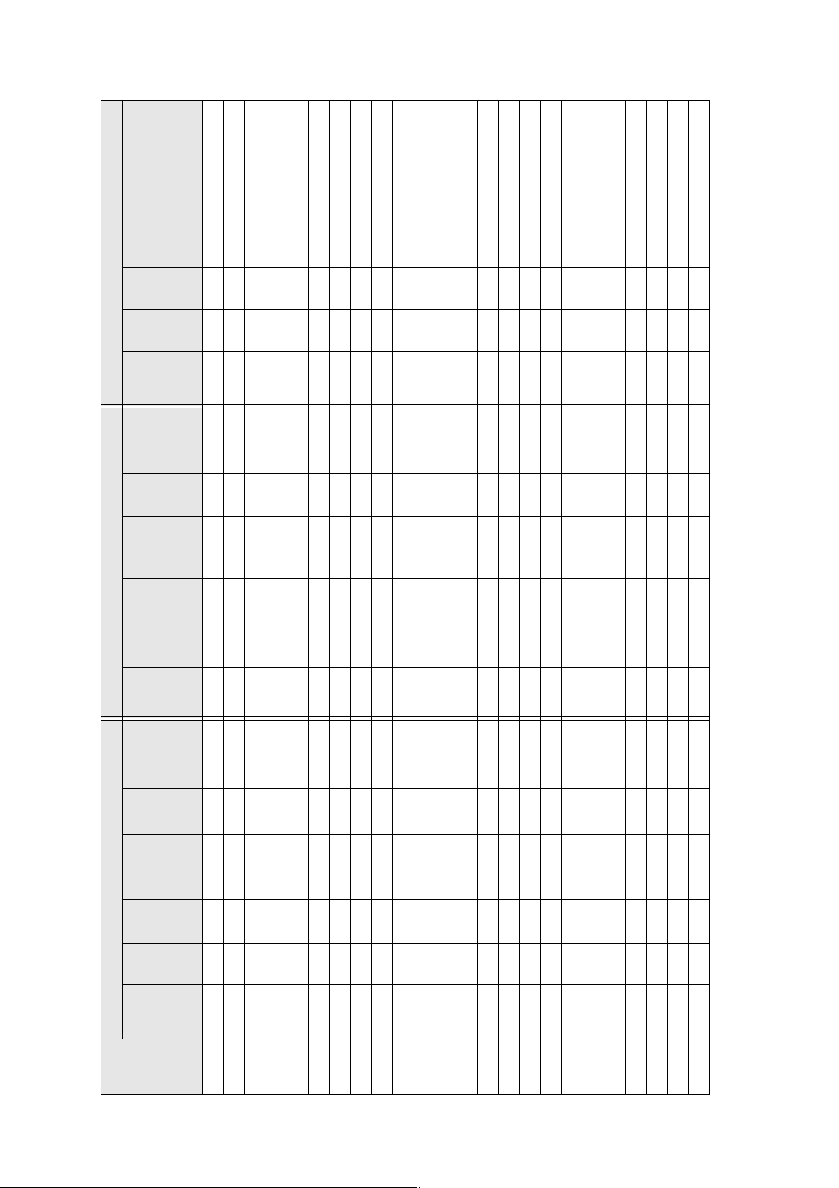
Page 23

Distance
from top of
scale
Slider
holes (c)
image to
wall plate
(b)
mark
English
Min.
projection
Image
height
width
Image
Min.
ceiling
Distance
from top of
scale
Slider
Min.
projectio
Image
height
distance
(h)
(w)
height*
image to
mark
n distance
(h)
(a)
wall plate
(b)
(a)
75.8 45.3 25.5 2.6 6.1 10.3
holes(c)
4:3 XGA 16:10 WXGA 16:9 Widescreen
width
Image
Min.
ceiling
Distance
from top of
scale
Slider
Min.
projection
Image
height
width
Image
Min.
ceiling
(w)
height*
image to
mark
distance (a)
(h)
(w)
height*
76.9 44.9 28.1 2.5 5.9 8.8 76.4 46.2 26.0 2.9 6.3 10.5
77.6 45.8 28.6 2.8 6.2 9.0 77.1 47.1 26.5 3.2 6.6 10.7
78.2 46.6 29.2 3.1 6.5 9.1 77.8 47.9 27.0 3.5 6.9 10.8
holes (c)
wall plate
(b)
79.6 44.8 33.6 2.5 5.9 6.0 78.9 47.5 29.7 3.4 6.8 9.3 78.5 48.8 27.5 3.8 7.2 11.0
80.3 45.6 34.2 2.7 6.1 6.1 79.6 48.3 30.2 3.6 7.0 9.4 79.2 49.7 27.9 4.1 7.5 11.2
80.9 46.4 34.8 3.0 6.4 6.2 80.3 49.2 30.7 3.9 7.3 9.6 79.8 50.6 28.4 4.4 7.8 11.4
81.7 47.2 35.4 3.3 6.7 6.3 81.0 50.0 31.3 4.2 7.6 9.7 80.5 51.4 28.9 4.6 8.1 11.6
82.3 48.0 36.0 3.5 6.9 6.4 81.7 50.9 31.8 4.5 7.9 9.9 81.2 52.3 29.4 4.9 8.3 11.8
83.1 48.8 36.6 3.8 7.2 6.5 82.4 51.7 32.3 4.7 8.1 10.0 81.9 53.2 29.9 5.2 8.6 12.0
83.7 49.6 37.2 4.1 7.5 6.6 83.1 52.6 32.9 5.0 8.4 10.2 82.6 54.0 30.4 5.5 8.9 12.2
84.4 50.4 37.8 4.3 7.7 6.6 83.7 53.4 33.4 5.3 8.7 10.4 83.2 54.9 30.9 5.8 9.2 12.3
85.1 51.2 38.4 4.6 8.0 6.7 84.4 54.3 33.9 5.6 9.0 10.5 83.9 55.8 31.4 6.1 9.5 12.5
85.9 52.0 39.0 4.8 8.2 6.8 85.1 55.1 34.4 5.8 9.3 10.7 84.6 56.7 31.9 6.4 9.8 12.7
86.5 52.8 39.6 5.1 8.5 6.9 85.8 56.0 35.0 6.1 9.5 10.8 85.3 57.5 32.4 6.6 10.0 12.9
87.2 53.6 40.2 5.4 8.8 7.0 86.5 56.8 35.5 6.4 9.8 11.0 85.9 58.4 32.9 6.9 10.4 13.1
87.9 54.4 40.8 5.6 9.0 7.1 87.2 57.7 36.0 6.7 10.1 11.1 86.6 59.3 33.3 7.2 10.6 13.3
88.6 55.2 41.4 5.9 9.3 7.2 87.9 58.5 36.6 7.0 10.4 11.3 87.3 60.1 33.8 7.5 10.9 13.5
89.3 56.0 42.0 6.1 9.6 7.3 88.5 59.4 37.1 7.2 10.7 11.4 88.0 61.0 34.3 7.8 11.2 13.7
90.0 56.8 42.6 6.4 9.8 7.4 89.2 60.2 37.6 7.5 10.9 11.6 88.6 61.9 34.8 8.1 11.5 13.8
90.7 57.6 43.2 6.7 10.1 7.5 89.9 61.1 38.2 7.8 11.2 11.8 89.3 62.8 35.3 8.3 11.6 14.0
91.4 58.4 43.8 6.9 10.4 7.6 90.6 61.9 38.7 8.1 11.5 11.9 90.0 63.6 35.8 8.6 12.0 14.2
92.1 59.2 44.4 7.2 10.6 7.7 91.3 62.8 39.2 8.3 11.8 12.1 90.7 64.5 36.3 8.9 12.3 14.4
Installation Measurements in Inches for XGA Projectors
Diagonal
image
size
(S)
52” — — —— —— — ——— ——
53” ———— ——
54” ———— ——
55” ———— ——
56”
57”
58”
59”
60”
61”
62”
63”
64”
65”
66”
67”
68”
69”
70”
71”
72”
73”
74”
23
Page 24
Distance
from top of
scale
Slider
image to
wall plate
(b)
mark
holes (c)
Min.
Image
Image
Min.
Distance
Slider
Min.
Image
distance
projection
(h)
height
(w)
width
ceiling
height*
image to
from top of
scale
mark
projectio
n distance
(h)
height
(a)
holes(c)
wall plate
(b)
(a)
———
12.1 12.1 16.5
41.7
—
———
—
———
———
—
—
———
———
—
—
4:3 XGA 16:10 WXGA 16:9 Widescreen
Image
Min.
Distance
Slider
Min.
Image
Image
Min.
width
ceiling
from top of
scale
projection
height
width
ceiling
(w)
height*
holes (c)
image to
wall plate
(b)
mark
distance (a)
(h)
(w)
height*
93.5 60.8 45.6 7.7 7.7 7.9 92.6 64.4 40.3 8.9 8.9 12.4 92.0 66.2 37.3 9.5 9.5 14.8
94.2 61.6 46.2 8.0 8.0 8.0 93.3 65.3 40.8 9.2 9.2 12.5 92.7 67.1 37.8 9.8 9.8 15.0
94.9 62.4 46.8 8.2 8.2 8.1 94.0 66.1 41.3 9.5 9.5 12.7 93.4 68.0 38.2 10.1 10.1 15.1
95.6 63.2 47.4 8.5 8.5 8.2 94.7 67.0 41.9 9.7 9.7 12.8 94.1 68.9 38.7 10.3 10.3 15.3
96.3 64.0 48.0 8.8 8.8 8.3 95.4 67.8 42.4 10.0 10.0 13.0 94.7 69.7 39.2 10.6 10.6 15.5
97.0 64.8 48.6 9.0 9.0 8.4 96.1 68.7 42.9 10.3 10.3 13.2 95.4 70.6 39.7 10.9 10.9 15.7
97.7 65.6 49.2 9.3 9.3 8.5 96.8 69.5 43.5 10.6 10.6 13.3 96.1 71.5 40.2 11.2 11.2 15.9
98.4 66.4 49.8 9.5 9.5 8.6 97.4 70.4 44.0 10.8 10.8 13.5 96.8 72.3 40.7 11.5 11.5 16.1
99.1 67.2 50.4 9.8 9.8 8.7 98.1 71.2 44.5 11.1 11.1 13.6 97.5 73.2 41.2 11.8 11.8 16.3
99.8 68.0 51.0 10.1 10.1 8.8 98.8 72.1 45.0 11.4 11.4 13.8 98.1 74.1
100.5 68.8 51.6 10.3 10.3 8.9 99.5 72.9 45.6 11.7 11.7 13.9 — —
101.2 69.6 52.2 10.6 10.6 9.0 100.2 73.8 46.1 12.0 12.0 14.1 — —
101.9 70.4 52.8 10.9 10.9 9.1 100.9 74.6 46.6 12.2 12.2 14.2 — —
102.6 71.2 53.4 11.1 11.1 9.2 — — — — — — — —
103.3 72.0 54.0 11.4 11.4 9.3 — — — — — — — —
104.0 72.8 54.6 11.6 11.6 9.4 — — — — — — — —
104.6 73.6 55.2 11.9 11.9 9.5 — — — — — — — — — — — —
105.3 74.4 55.8 12.2 12.2 9.6 — — — — — — — — — — — —
image
Diagonal
(S)
size
75” 92.8 60.0 45.0 7.4 7.4 7.8 92.0 63.6 39.7 8.6 8.6 12.2 91.4 65.4 36.8 9.2 9.2 14.6
76”
77”
78”
79”
80”
81”
82”
83”
84”
85”
86”
87”
88”
90”
91”
92”
89”
93”
* Based on an image 30 inches from the floor; if the image is lower, the minimum ceiling height is reduced by the corresponding measurement.
24
Page 25

Distance
from top of
scale
Slider
holes (c)
image to
wall plate
(b)
mark
English
Min.
Projection
Image
height
width
Image
Min.
ceiling
Distance
from top
scale
Slider
Min.
projection
Image
height
(a)
distance
(h)
(w)
height*
wall plate
of image to
(b)
mark
(a)
distance
(h)
holes (c)
16:10 WXGA 4:3 XGA 16:9 Widescreen
width
Image
Min.
ceiling
Distance
from top of
scale
Slider
Min.
projection
Image
height
width
Image
Min.
ceiling
(w)
height*
image to
wall plate
(b)
mark
(a)
distance
(h)
(w)
height*
holes (c)
1998 1077 808 62 149 174 — — — — — —
2016 1097 823 69 156 177 — — — — — —
2034 1118 838 76 163 180 — — — — — —
2052 1138 853 83 170 183 — — — — — —
2071 1158 869 91 178 186 — — — — — —
2089 1179 884 98 185 189 — — — — — —
2107 1199 899 105 192 192 1968 1306 735 66 153 217
1998 1292 808 62 149 174 2125 1219 914 112 199 195 1983 1328 747 73 160 220
2014 1314 821 69 156 177 2144 1240 930 119 206 198 1999 1350 760 79 166 223
2030 1335 835 75 162 179 2162 1260 945 126 213 201 2015 1373 772 86 173 227
2046 1357 848 81 168 182 2180 1280 960 133 220 204 2031 1395 785 92 179 230
2063 1379 862 87 174 185 2198 1300 975 140 227 207 2047 1417 797 98 185 234
2078 1400 875 93 180 187 2217 1321 991 147 234 210 2062 1439 809 105 192 237
2094 1422 888 100 187 190 2235 1341 1006 154 241 213 2079 1461 822 111 198 241
2111 1443 902 106 193 193 2253 1361 1021 161 248 216 2094 1483 834 117 204 244
2126 1465 915 112 199 195 2271 1382 1036 168 256 219 2111 1505 847 124 211 248
2143 1486 929 118 205 198 2290 1402 1052 175 262 222 2126 1528 859 130 217 251
2159 1508 942 124 211 201 2308 1422 1067 182 269 225 2142 1550 872 137 224 254
2175 1529 956 131 218 203 2326 1443 1082 189 276 228 2158 1572 884 143 230 258
2191 1551 969 137 224 206 2345 1463 1097 196 283 232 2174 1594 897 149 236 261
2208 1572 983 143 230 209 2364 1483 1113 203 290 235 2190 1616 909 156 243 265
2223 1594 996 149 236 211 2382 1504 1128 210 297 238 2205 1638 921 162 249 268
2240 1615 1010 155 155 214 2400 1524 1143 217 217 241 2222 1660 934 168 168 272
2256 1637 1023 162 162 217 2418 1544 1158 224 224 244 2237 1682 946 175 175 275
Installation Measurements in Millimeters for WXGA Projectors
Diagonal
image
size
(S)
54” ———— ——
53” ———— ——
55” ———— ——
56” ———— ——
57” ———— ——
58” ———— ——
59” ———— ——
60”
61”
62”
63”
64”
65”
66”
67”
68”
69”
70”
71”
72”
73”
74”
75”
76”
25
Page 26
Distance
Slider
from top of
scale
image to
wall plate
(b)
mark
holes (c)
Min.
Image
Image
Min.
Distance
Slider
Min.
Image
Projection
height
width
ceiling
from top
scale
projection
height
(a)
distance
(h)
(w)
height*
wall plate
of image to
(b)
mark
(a)
distance
(h)
holes (c)
16:10 WXGA 4:3 XGA 16:9 Widescreen
Image
Min.
Distance
Slider
Min.
Image
Image
Min.
(w)
width
ceiling
height*
image to
from top of
scale
mark
distance
projection
(h)
height
(w)
width
ceiling
height*
holes (c)
wall plate
(b)
(a)
2288 1680 1050 174 174 222 2455 1585 1189 238 238 250 2269 1727 971 188 188 282
2304 1702 1063 180 180 225 2473 1605 1204 245 245 253 2285 1749 984 194 194 285
2320 1723 1077 187 187 227 2491 1626 1219 252 252 256 2301 1771 996 200 200 289
2336 1745 1090 193 193 230 2509 1646 1234 259 259 259 2317 1793 1009 207 207 292
2353 1766 1104 199 199 233 2528 1666 1250 266 266 262 2333 1815 1021 213 213 296
2368 1788 1117 205 205 235 2546 1687 1265 273 273 265 2349 1837 1034 219 219 299
2385 1809 1131 211 211 238 2564 1707 1280 280 280 268 2365 1860 1046 226 226 303
2401 1831 1144 218 218 241 2582 1727 1295 287 287 271 2380 1882 1058 232 232 306
2417 1852 1158 224 224 243 2601 1748 1311 294 294 274 2396 1904 1071 239 239 309
2433 1874 1171 230 230 246 2619 1768 1326 301 301 277 2412 1926 1083 245 245 313
2450 1895 1185 236 236 249 2637 1788 1341 308 308 280 2428 1948 1096 251 251 316
2466 1917 1198 242 242 252 — — — — — — 2444 1970 1108 258 258 320
2482 1939 1212 249 249 254 — — — — — — 2460 1992 1121 264 264 323
2498 1960 1225 255 255 257 — — — — — — 2476 2015 1133 270 270 327
2515 1982 1239 261 261 260 — — — — — — 2492 2037 1146 277 277 330
2530 2003 1252 267 267 262 — — — — — — 2507 2059 1158 283 283 333
2546 2025 1265 273 273 265 — — — — — — 2524 2081 1171 290 290 337
2563 2046 1279 280 280 268 — — — — — — 2539 2103 1183 296 296 340
2578 2068 1292 286 286 270 — — — — — — 2555 2125 1195 302 302 344
2595 2089 1306 292 292 273 — — — — — — 2571 2147 1208 309 309 347
2611 2111 1319 298 298 276 — — — — — — — — — — — —
2627 2132 1333 304 304 278 — — — — — — — — — — — —
2643 2154 1346 311 311 281 — — — — — — — — — — — —
image
Diagonal
(S)
size
77” 2272 1659 1037 168 168 219 2436 1565 1173 231 231 247 2253 1705 959 181 181 278
78”
79”
80”
81”
82”
83”
84”
85”
86”
87”
88”
89”
90”
91”
92”
93”
94”
95”
96”
99”
97”
98”
100”
* Based on an image 762 mm from the floor; if the image is lower, the minimum ceiling height is reduced by the corresponding measurement.
26
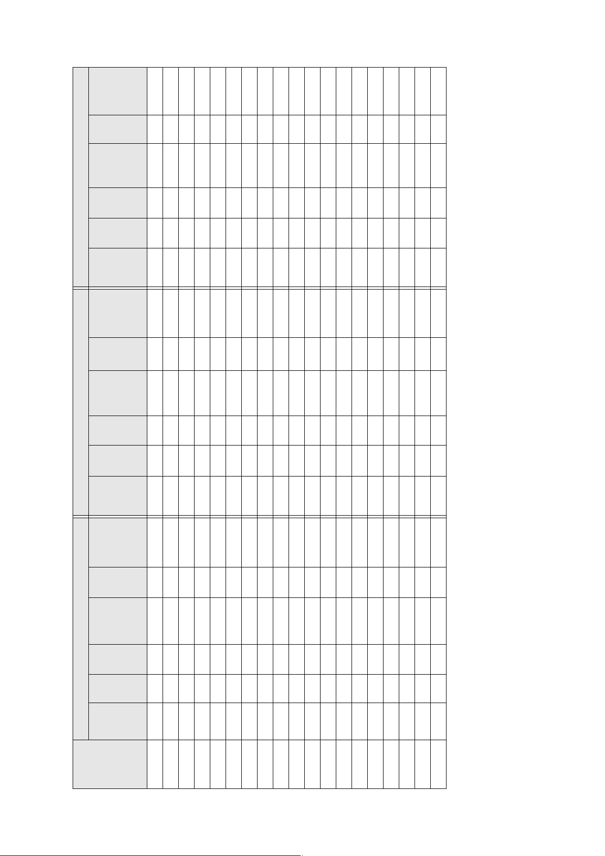
Page 27
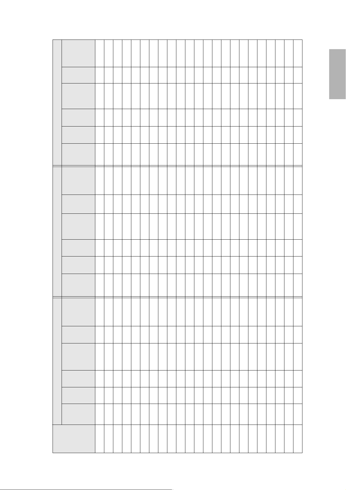
image to
wall plate
(b)
mark
holes (c)
English
Distance
from top of
scale
Slider
Min.
Projection
Image
height
width
Image
Min.
ceiling
Distance
from top of
scale
Slider
Min.
projection
Image
height
(a)
distance
(h)
(w)
height*
holes (c)
image to
wall plate
(b)
mark
(a)
distance
(h)
(w)
width
Image
Min.
ceiling
height*
image to
wall plate
(b)
mark
(a)
distance
(h)
(w)
height*
holes (c)
Distance
from top of
scale
Slider
Min.
projection
4:3 XGA 16:10 WXGA 16:9 Widescreen
Image
height
width
Image
Min.
ceiling
nstallation Measurements in Millimeters for XGA Projectors
Diagonal
(S)
image size
52” — — — — — — — — — — — — 1925 1151 648 67 154 261
53” — — — — — — 1952 1142 713 64 151 223 1942 1173 660 74 161 266
54” — — — — — — 1970 1163 727 71 158 227 1959 1195 672 81 168 271
55” — — — — — — 1987 1185 740 78 165 231 1976 1218 685 89 176 275
56” 2021 1138 853 63 150 152 2005 1206 754 85 172 235 1993 1240 697 96 183 280
57” 2039 1158 869 69 156 154 2022 1228 767 92 179 239 2011 1262 710 103 190 285
58” 2056 1179 884 76 163 156 2040 1249 781 99 186 243 2028 1284 722 110 197 290
59” 2074 1199 899 83 170 159 2057 1271 794 106 193 247 2045 1306 735 118 205 294
60” 2091 1219 914 89 176 161 2075 1292 808 113 200 251 2062 1328 747 125 212 299
61” 2110 1240 930 96 183 164 2092 1314 821 120 207 255 2080 1350 760 132 219 304
62” 2127 1260 945 103 190 166 2110 1335 835 127 214 259 2097 1373 772 139 226 309
63” 2145 1280 960 109 196 169 2127 1357 848 134 221 263 2114 1395 785 147 234 313
64” 2162 1300 975 116 203 171 2145 1379 862 141 228 267 2131 1417 797 154 241 318
65” 2181 1321 991 122 209 174 2162 1400 875 148 235 271 2148 1439 809 161 248 323
66” 2198 1341 1006 129 216 176 2179 1422 888 155 242 275 2166 1461 822 168 255 328
67” 2216 1361 1021 136 223 179 2197 1443 902 163 250 279 2182 1483 834 176 263 332
68” 2233 1382 1036 142 229 181 2214 1465 915 170 257 283 2200 1505 847 183 270 337
69” 2251 1402 1052 149 236 183 2232 1486 929 177 264 287 2217 1528 859 190 277 342
70” 2269 1422 1067 156 243 186 2249 1508 942 184 271 291 2235 1550 872 197 284 347
71” 2286 1443 1082 162 249 188 2266 1529 956 191 278 294 2251 1572 884 205 292 351
72” 2304 1463 1097 169 256 191 2283 1551 969 198 285 298 2269 1594 897 212 294 356
73” 2322 1483 1113 176 263 193 2301 1572 983 205 292 302 2286 1616 909 219 306 361
74” 2340 1504 1128 182 269 196 2318 1594 996 212 299 306 2303 1638 921 226 313 366
27
Page 28
Distance
from top of
scale
Slider
image to
mark
holes (c)
wall plate
(b)
Min.
Projection
Image
height
width
Image
Min.
ceiling
Distance
from top of
scale
Slider
Min.
projection
Image
height
distance
(h)
(w)
height*
image to
mark
distance
(h)
(a)
holes (c)
wall plate
(b)
(a)
4:3 XGA 16:10 WXGA 16:9 Widescreen
width
Image
Min.
ceiling
Distance
from top of
scale
Slider
Min.
projection
Image
height
width
Image
Min.
ceiling
(w)
height*
image to
mark
distance
(h)
(w)
height*
wall plate
(b)
(a)
holes (c)
(S)
Diagonal
image size
75” 2357 1524 1143 189 189 198 2336 1615 1010 219 219 310 2320 1660 934 234 234 370
76” 2375 1544 1158 196 196 201 2353 1637 1023 226 226 314 2337 1682 946 241 241 375
77” 2392 1565 1173 202 202 203 2371 1659 1037 233 233 318 2355 1705 959 248 248 380
78” 2411 1585 1189 209 209 206 2388 1680 1050 240 240 322 2372 1727 971 255 255 385
79” 2428 1605 1204 216 216 208 2405 1702 1063 247 247 326 2389 1749 984 263 263 389
80” 2446 1626 1219 222 222 211 2423 1723 1077 254 254 330 2406 1771 996 270 270 394
81” 2463 1646 1234 229 229 213 2440 1745 1090 261 261 334 2424 1793 1009 277 277 399
82” 2481 1666 1250 236 236 215 2458 1766 1104 268 268 338 2441 1815 1021 284 284 404
83” 2499 1687 1265 242 242 218 2475 1788 1117 275 275 342 2458 1837 1034 292 292 408
84” 2516 1707 1280 249 249 220 2493 1809 1131 282 282 346 2475 1860 1046 299 299 413
85” 2534 1727 1295 256 256 223 2510 1831 1144 289 289 350 2492 1882 1058 306 306 418
86” 2552 1748 1311 262 262 225 2528 1852 1158 297 297 354 — — — — — —
87” 2570 1768 1326 269 269 228 2545 1874 1171 304 304 358 — — — — — —
88” 2587 1788 1341 275 275 230 2563 1895 1185 311 311 362 — — — — — —
89” 2605 1808 1356 282 282 233 — — — — — — — — — — — —
90” 2623 1829 1372 289 289 235 — — — — — — — — — — — —
91” 2641 1849 1387 295 295 238 — — — — — — — — — — — —
92” 2658 1869 1402 302 302 240 — — — — — — — — — — — —
93” 2675 1890 1417 309 309 242 — — — — — — — — — — — —
* Based on an image 762 mm from the floor; if the image is lower, the minimum ceiling height is reduced by the corresponding measurement.
28
Page 29
If you have a pre-existing interactive whiteboard, refer to the table below to identify common models and
sizes. If your board is listed here, use the dimensions to reference the installation requirements found on
pages 21 to 28.
Interactive whiteboard sizes
Diagonal size 16:10 WXGA 4:3 XGA 16:9 Widescreen
57 inches — PolyVision TS410 —
60 inches — Hitachi® Cambridge board 60
RM ClassBoard2 60
INTERWRITE BOARD 1060
INTERWRITE Dual board 1260
63 inches — Hitachi® StarBoard FX-63 —
64 inches — SMART Board 660
Promethean ActivBoard 164
66 inches — TeamBoard RT TMWM5422CL/EM —
71 inches — — INTERWRITE BOARD 1071
75 inches PolyVision® eno2650 — —
77 inches — Hitachi Cambridge Board 77
Hitachi StarBoard FX DUO 77
SMART Board 680
SMART BoardX880
INTERWRITE® BOARD 1077
TeamBoard RT TMWM6250CL/EM
77.5 inches — RM ClassBoard2 77.5 —
78 inches PolyVision TS 600/ TS620 / TSL620 PolyVision TS610
Promethean ActivBoard 178 / 378
79 inches — INTERWRITE Dual Board 1279 —
80 inches — — RM Classboard 85
82 inches — — Hitachi StarBoard FX-82W
85 inches TeamBoard RT TMWM7450EM — INTERWRITE BOARD 1085
87 inches
88 inches Hitachi StarBoard FX DUO-88W — —
89 inches — INTERWRITE Dual Board 1289 —
93 inches — — PolyVision ENO 2810
94 inches — — SMART Board 690
95 inches — — INTERWRITE BOARD 1095
SMART Board
SMART Board
Promethean ActivBoard 387
Promethean ActivBoard 587 pro
™ 685
X 885
——
—
—
INTERWRITE Dual board 1277
—
INTERWRITE Dual Board 1285
INTERWRITE Dual Board 1295
Promethean ActivBoard 395
Promethean ActivBoard 595 pro
English
29
Page 30
5 Installing the Projector
Make sure to follow the steps below to install the wall mount. If you ignore these steps, the wall mount could
fall and cause personal injury or property damage.
Warning
❏ When you mount the projector on the wall with the wall mount, the wall requires enough
strength to hold the projector and the wall mount.
This wall mount should be installed on a concrete wall. Confirm the weight of the projector
and the wall mount before installation, and maintain the strength of the wall. If the wall is
not strong enough, reinforce the wall before installation.
❏ The maximum combined weight of the projector and the wall mount is 32.6 lb (14.8 kg).
❏ Do not hang the rest of the cable over the wall mount.
❏ Install the wall mount so that it can sufficiently support the weight of the projector and
wall mount, and resist any horizontal vibration. Use M10 nuts and bolts and make sure to
use appropriate wall anchors for your wall type. Nuts and bolts smaller than M10 could
cause the wall mount to fall.
❏ Epson accepts no responsibility for any damage or injury caused by lack of wall strength or
inadequate installation.
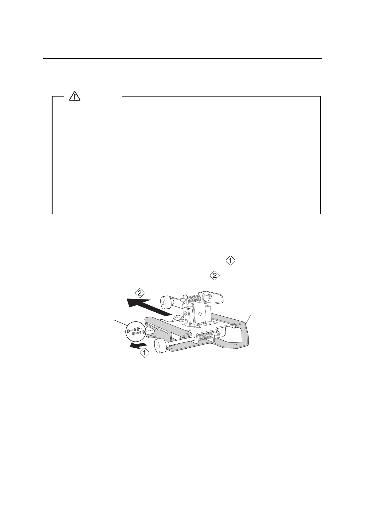
A Disassemble the parts
Remove the slide plate from the 3-axis adjustment unit.
• Remove the M4 × 12 mm hexagon socket head cap bolts (x2) ( ).
• Remove the slide plate from the 3-axis adjustment unit ( .
M4 × 12 mm hexagon
socket head cap bolts
(×2)
Slide plate
30
Page 31

B Assemble the parts
1. Assemble the wall plate.
Assemble the three plates into one unit, and secure them with the M4 × 12 mm hexagon socket head
cap bolts (×6) supplied.
Wash er
Spring washer
M4 × 12 mm hexagon socket head cap bolts
2. Attach the slide plate to the projector.
Attach the slide plate to the projector using the M4 × 12 mm hexagon socket head cap bolts (×4)
supplied.
M4 × 12 mm hexagon socket head cap
Slide plate
bolts
English
Spring washer
Wash er
31
Page 32

3. Attach the 3-axis adjustment unit to the wall mount.
• Decide which position you want to use for installing the 3-axis adjustment unit.
Mount it at the stamp when the image is less than 75 inches (diagonally), or at the stamp
when the projected image is 75 inches or more (diagonally).
: Less than 75 inches
: 75 inches or more
• Tighten the M4 × 12 mm hexagon socket head cap bolts (×4) supplied to install the 3-axis
adjustment unit.
M4 × 12 mm hexagon
socket head cap bolts
Spring washer
Was her
Bolt installation positions
When the diagonal image is less than 75 inches
When the diagonal image is 75 inches or more
32
Page 33

C Install the wall plate on the wall
1. Determine the template sheet position.
• From the projection distance table, confirm the screen size (S) and the distance between the
projection surface and wall plate bottom holes (c).
• Align the Image Center line (vertical) of the template sheet with the center line (vertical) of the
projection surface.
Confirm where the beams or studs are within the wall, and shift the position of the template left or
right as necessary.
The position can be shifted horizontally left or right from the center line of the projection surface up
to a maximum of 1.77 in. (45 mm.)
• Align the line (horizontal) on the template with the height of (c).
2.8 in.
(70.5 mm)
Image Center line of template sheet
line of template sheet
English
Center line of
projection surface
2. Attach the template sheet to the wall.
If you need to install a junction box, you can use the cutout areas in the wall plate for the box. The
junction box needs to be recessed into the wall if you want to use the wall plate cover, or you can use
the wall plate cover extender.
33
Page 34

3. Determine the position of the wall plate’s mounting holes.
Use at least three mounting holes.
• If you are securing the wall plate in four places, drill the holes indicated by A or B in the illustration
below.
• If you are securing the wall plate in three places, drill the holes indicated by C in the illustration
below.
Four mounting holes
Steps 4 to 8 below provide instructions for attaching the wall plate to a concrete wall.
4. Drill holes of the following diameters and depths.
Drill diameter 0.41 in. (10.5 mm)
Pilot hole depth 1.8 in. (45 mm)
Anchor hole depth 1.6 in. (40 mm)
5. Remove the template sheet.
6. Use a device such as a dust pump to clean out concrete dust from the hole.
Three mounting holes
7. Position the wall plate on the wall and insert M10 × 60 mm expansion anchors into the holes. Attach
the nut and tap it with a hammer until the core touches the top of the anchor.
34
Page 35

8. Tighten the nut with a wrench to secure the wall plate to the wall.
D Determine the projection distance and pull out the slider
1. Using the tables on pages 21 to 28, check the number for the slider measure (b).
2. Loosen the M4 × 12 mm hexagon socket head cap bolts (×2), and then pull out the slider on the wall
mount.
Align the slider with the measure (b+x) that is equal to the slider measure (b) plus the thickness of the
projection screen (x).
For an illustration of how to measure the thickness of the projection screen (x), see page 19.
M4 × 12 mm hexagon socket head cap bolts (×2)
English
Slider measure
35
Page 36

E Route the cables through the wall mount arm
BrightLink 595Wi/595Wi+ and BrightLink Pro 1430Wi: Make sure to route the Touch
Unit connection cable through the wall mount arm. Route the Touch Unit connection
cable so that the end that connects to the Touch Unit appears from the lower part of
the wall mount as shown.
Touch U ni t
connection cable
F Attach the mount arm to the wall plate
1. Insert the hexagonal shaft into the wall mount ( ).
36
Page 37
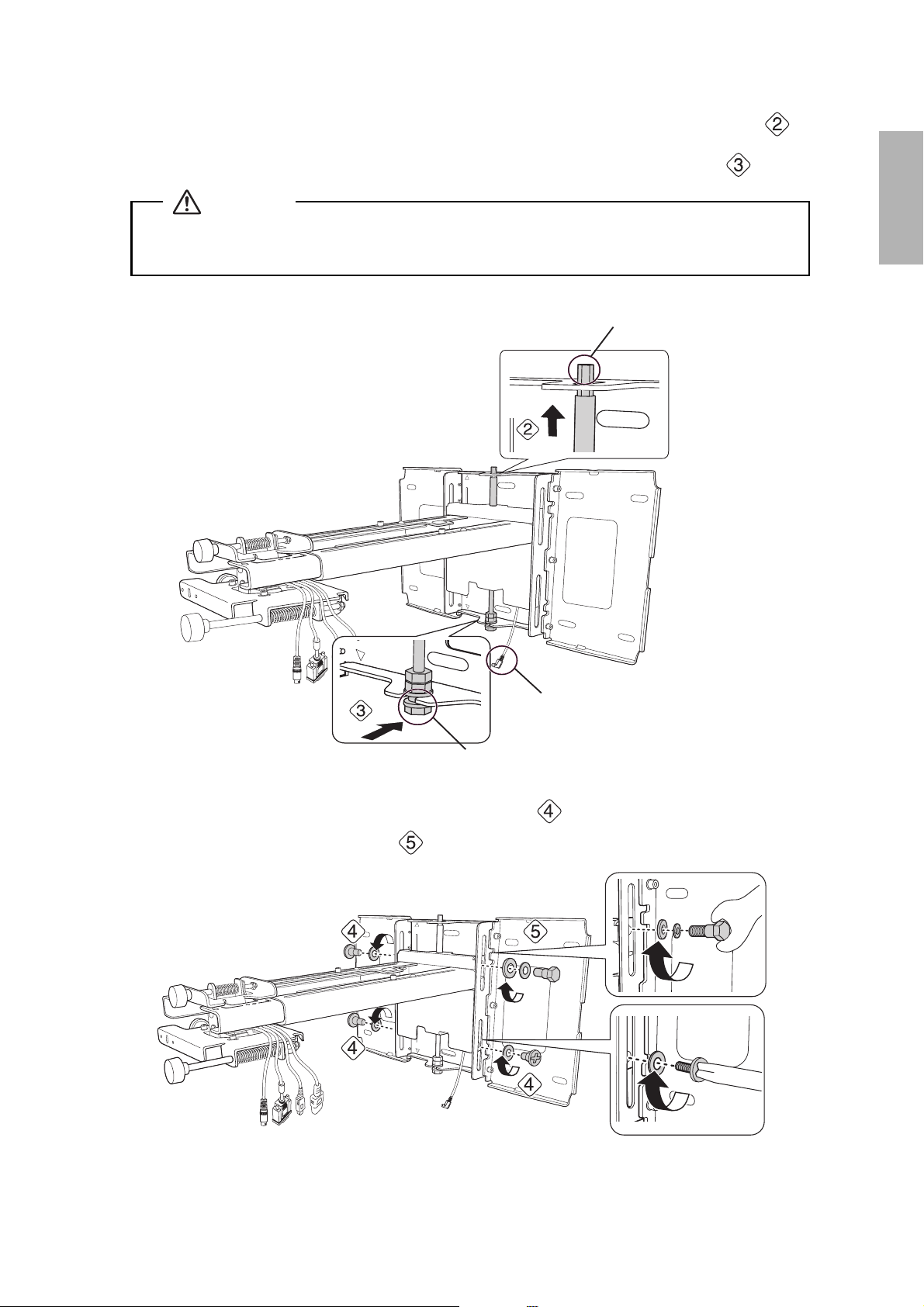
2. Insert and turn the hexagonal shaft at the top of the mount arm into the slot on the wall plate ( ).
3. Insert and turn the M8 hexagon bolt at the bottom of the mount arm into the wall plate ( ).
Caution
❏ Make sure the Touch Unit connection cable is not wired into the wall with the other cables.
❏ Take care not to trap the cables between the mount arm and wall plate.
Hexagonal shaft
English
Touch Unit connection cable
M8 hexagonal bolt
4. Secure the mount arm to the wall plate by tightening the supplied M6 × 20 mm cross recessed head
shoulder screws (×3) with the No.3 cross-head screwdriver ( ). Then, loosely tighten the M6 × 20
mm hexagon shoulder bolt supplied ( ).
M6 × 20 mm cross recessed
head shoulder screws (×3)
37
Page 38

G Adjust the vertical slide position of the arm
1. Adjust the vertical slide with the M8 hexagon bolt at the bottom of the wall mount, or the hexagonal
shaft at the top of the wall mount ( ). Start by aligning the notch on the arm with the stamp on the
wall plate as shown below.
Tightening the M8 hexagon bolt lowers the wall mount, and loosening the bolt raises it.
Tightening the hexagonal shaft raises the wall mount, and loosening the shaft lowers it.
Hexagonal shaft
M8 hexagon
bolt
Alignment marks
2. Tighten the M6 × 20 mm hexagon shoulder bolt to secure the wall mount ( ).
38
Page 39

H Attach the projector to the wall mount
1. Loosen the two screws with a Phillips head screwdriver and remove the cable cover from the projector.
Cable coverScrews (x2)
2. Insert the slide plate into the wall mount from the interface side of the projector ( ).
Align the 3-axis adjustment unit with the slide plate’s alignment mark ( ).
3. Tighten the M4 × 12 mm hexagon socket head cap bolts (×2) ( ).
Slide plate
English
Projector
interface side
Bolt positions
Wash er
Spring washer
M4 × 12 mm hexagon socket head cap bolts
Alignment marks
Warning
When installing or adjusting the wall mount, do not use adhesives to prevent the screws from
loosening and do not use lubricants or oils on the projector slide plate. This may cause the case
to crack and the projector to fall, resulting in personal injury or property damage.
39
Page 40

I Connect the power cord and other cables to the projector
Connect any necessary cables such as the computer cable, HDMI cable, USB cable, Touch Unit
connection cable, Control Pad cables, and power cord to the projector. See your projector’s User Guide
for detailed connection information.
Power cord
Computer
cable
USB cable
Connect the power cord last.
BrightLink 595Wi/595Wi+: When connecting to the Audio1, Audio2, and Computer1
ports, it is recommended that you connect the cables to the ports in the following
order: Audio1, Audio2, and then Computer1.
BrightLink Pro 1420Wi/1430Wi: When connecting to the Audio1, Audio Out, and
Computer1 ports, it is recommended that you connect the cables to the ports in the
following order: Audio1, Audio Out, and then Computer1.
If you are planning to run the cables inside the wall, make sure you follow all local electrical codes. If
you are running the cables outside the wall, use a cable management system to keep the cables from
obstructing the image. An optional cable management system is available from Epson (part #
ELPCK01).
Touch Unit
connection cable
40
Page 41

6 Adjusting the Image
To ensure the best image quality, follow the steps below to adjust the projected image.
Do not make adjustments with the Quick Corner or Keystone functions of the
projector. Doing so may result in a reduction in image quality and pen calibration.
Follow these guidelines for setting up the projector:
• Make sure the image is evenly rectangular, without distortion.
• Make sure the projector is tilted no more than ±3° vertically and horizontally in relation to the projected
image.
Projector model Remote control column
PowerLite 470/480/570/580
BrightLink 475W/480i/485W/575Wi/585Wi/595Wi
BrightLink 575Wi+/585Wi+/595Wi+
PowerLite 475W/485W/575W/585W
BrightLink Pro 1410Wi/1420Wi/1430Wi B
A
A Turn on the projector
Using the Remote Control
A
Using the Remote Control
B
Using the Control Panel
English
B Display the test pattern
1. Press the [Help] button.
Using the Remote Control
A
Using the Remote Control
Using the Control Panel
B
41
Page 42

2. Press the button on the remote control, or the [Wide] button on the control panel.
The test pattern is displayed.
Using the Remote Control
A/B
The test pattern contains a guide to help you adjust the displayed image if your screen’s aspect ratio is
the same as the projector’s native aspect ratio.
Using the Control Panel
C Change the aspect ratio if necessary
Each time you press the [Aspect] button on the remote control, the aspect name is displayed on the
screen and the aspect ratio changes. You will need to re-display the test pattern after changing the
aspect ratio.
Change the setting according to the signal for the connected equipment.
You may need to project content from a connected device in order to change the aspect ratio.
Remote Control
Alternatively, set the aspect ratio from the Signal menu - Aspect. Following is a list of available aspect
settings:
BrightLink 480i and PowerLite 570/580
Aspect Ratio
Normal
• Auto: Automatically sets the aspect ratio according to the input signal and the Resolution setting
(available only for HDMI image sources).
• Normal: Displays images using the full projection area and maintains the aspect ratio of the image.
Choose this setting or Auto to automatically resize the image and make the best use of the display
area.
• 4:3: Displays images using the full projection area at 4:3 aspect ratio.
• 16:9: Converts the aspect ratio of the image to 16:9. 4:3 ratio images are elongated horizontally to fit.
42
Page 43

BrightLink Pro 1410Wi/1420Wi/1430Wi, BrightLink 575Wi/575Wi+/585Wi/585Wi+/595Wi/
595Wi+, and PowerLite 575W/585W
• Auto: Automatically sets the aspect ratio according to the input signal and the Resolution setting
(available only for HDMI image sources).
• Normal: Displays images using the full projection area and maintains the aspect ratio of the image.
Choose this setting or Auto to automatically resize the image and make the best use of the display
area.
• 16:9: Converts the aspect ratio of the image to 16:9. 4:3 ratio images are elongated horizontally to fit.
• Full: Displays images using the full width of the projection area, but does not retain the aspect ratio.
4:3 ratio images are elongated horizontally.
• Zoom: Displays images using the full width of the projection area and maintains the aspect ratio of
the image. The image may be cut off on the top and bottom depending on its aspect ratio.
• Native: Displays images as is (aspect ratio and resolution are maintained). Black bands may appear
or images may be cut off, depending on the resolution.
s Projector User's Guide: Signal Menu
D Adjust the focus
1. Slide the air filter cover switch ( ) to open the air filter cover ( ).
English
2. Use the focus lever to adjust the focus ( ).
Focus lever
Air filter cover
3. After you finish making the adjustment, close the air filter cover.
43
Page 44

E Use the adjustment knob on the left side to adjust the horizontal roll
Repeat steps
test pattern as shown in step
1. Loosen the screw ( ) to unlock the adjustment knob.
E to J as necessary. For each step, you may need to re-display the
B.
Screw
2. Turn the orange knob ( ) to adjust the horizontal roll ( ).
3. After you finish making all of the adjustments in steps
.
E to J, tighten the screw you loosened in
F Use the adjustment knob on the right side to adjust the horizontal
rotation
1. Loosen the screws (x2) to unlock the adjustment knob( ).
Screws (x2)
44
Page 45

2. Turn the dark blue knob ( ) to adjust the horizontal rotation ( ).
3. After you finish making all of the adjustments in steps
loosened in .
E to J, tighten the screws (x2) you
G Use the adjustment knob on the top to adjust the vertical tilt
1. Loosen the screw ( ) to unlock the adjustment knob.
English
Screw
2. Turn the light blue knob ( ) to adjust the vertical tilt ( ).
3. After you finish making all of the adjustments in steps
.
E to J, tighten the screw you loosened in
H Adjust the horizontal slide
1. Loosen the M4 × 12 mm hexagon socket head cap bolts (×2), and then adjust the slider for the slide
plate.
M4 × 12 mm hexagon socket
head cap bolts (×2)
45
Page 46

2. After you finish making all of the adjustments in steps E to J, tighten the M4 × 12 mm hexagon
socket head cap bolts (×2).
I Adjust the forward/backward slide
1. Loosen the M4 × 12 mm hexagon socket head cap bolts (×2), and then adjust the slider for the wall
mount.
M4 × 12 mm hexagon socket
head cap bolts (x2)
2. After you finish making all of the adjustments in steps
socket head cap bolts (×2).
E to J, tighten the M4 × 12 mm hexagon
J Adjust the vertical slide
1. Loosen the M6 × 20 mm hexagon shoulder bolt ( ).
2. Adjust the vertical slide with the M8 hexagon bolt at the bottom of the wall mount, or the hexagonal
shaft at the top of the wall mount ( ).
Tightening the M8 hexagon bolt lowers the wall mount, and loosening the bolt raises it.
Tightening the hexagonal shaft raises the wall mount, and loosening the shaft lowers it.
Hexagonal shaft
M6 × 20 mm hexagon shoulder bolt
M8 hexagon
bolt
3. Tighten the M6 × 20 mm hexagon shoulder bolt you loosened in the first step ( ).
46
Page 47

K Turn off the display of the test pattern
Press the [Esc] button on the remote control or control panel to turn off the test pattern.
Warning
Tighten all screws firmly. Otherwise, the projector or wall mount may fall and cause personal
injury or property damage.
7 Attaching the Covers
A Attach the wall plate cover and end cap
If you need to use a security cable, make sure you attach it before installing the wall plate cover. See
page 66 for instructions.
You can use the wall plate cover extender (if included) to increase the depth of the wall
plate cover and accommodate larger cables and plugs.
To add the extender, clip each half of the extender to the wall plate cover pieces before
you attach the cover to the mount.
Adding the wall plate cover extender limits the minimum size of the projected image.
See page 20 for more information.
1. Attach the wall plate cover ( ). Snap the tabs on the cover into the holes on the wall plate. (If you
need to remove the cover, press the tabs.)
English
Depending on how the cables are wired, you may need to cut out parts of the wall
plate cover to allow the cables to be passed through it.
When cutting the thin section of the wall plate cover and passing the cables through,
make sure you perform deburring to smooth off any sharp edges to prevent damaging
the cables.
Also, make sure you operate the cutter safely.
2. Place the end cap with the concave portion facing up ( ).
Wall plate cover
End cap
47
Page 48

B Attach the cable cover to the projector
Attach the cable cover and use a Phillips head screwdriver to tighten the screws (x2) and secure the
cable cover.
Screws (x2)
Cable cover
Caution
Only a specialist should remove or reinstall the projector, including for maintenance and
repairs. Refer to your projector’s User’s Guide for instructions on maintenance and repairs.
Warning
❏ Never loosen the bolts and nuts after installation. If you find any loose screws, tighten
them firmly. Otherwise, the projector or wall mount may fall and cause personal injury or
property damage.
❏ Do not hang on the wall mount or hang a heavy object on the wall mount. If the projector
or wall mount falls, it could cause personal injury or property damage.
48
Page 49

8 Installing the Touch Unit
The following procedures must have been completed before installing the Touch Unit:
• Installing the projector (see page 30)
• Adjusting the projected image (see page 41)
• Calibrating the interactive pen(s)
s Refer to your projector User's Guide or Start Here folder for detailed instructions.
❏ There are magnets built in to the back of the Touch Unit. Typically, the Touch Unit
should be installed by attaching the magnets to the screen or whiteboard.
❏ If the magnets cannot be attached, use commercially available M4 screws (×3).
❏ Install the Touch Unit on a flat, smooth, unwarped surface that is the same level
surface as the screen surface. If there is unevenness on the screen surface of more
than 0.2 inches (5 mm) in any direction, your fingers may not be detected and
finger touch operations may not be performed correctly.
Follow the steps below to install the Touch Unit and connect to the projector. Some menus may differ slightly
from the illustrations, but the installation instructions are the same.
Caution
The Touch Unit should only be connected to the BrightLink 595Wi/595Wi+ or BrightLink Pro
1430Wi models. Do not connect the Touch Unit to any other projectors or devices.
English
A Turn on the projector
Using the Remote Control
BrightLink 595Wi/595Wi+
Using the Remote Control
BrightLink Pro 1430Wi
B Display the installation pattern
1. Select Easy Interactive Function from the Extended menu.
Using the Control Panel
49
Page 50

2. Select Touch Unit Setup.
3. Select Installation Pattern.
The Installation pattern is displayed on the projected image.
C Remove the markers
1. Loosen the screw at the bottom of the dial cover.
50
Page 51

2. Slide the dial cover down to remove it.
3. Remove the two markers from inside the Touch Unit.
Use the markers to perform the angle adjustment (p. 53) after installing the Touch Unit.
English
D Determine the installation position for the Touch Unit
Mark the following installation positions:
• ( ): The center line of the installation pattern; align it with the center line of the Touch Unit ( ).
• ( ): 1 inch (25 mm) from the top edge of the projected image; align with the bottom edge of the
Touch U n i t .
1.0 in. (25 mm)
The Touch Unit must be installed above the image area.
51
Page 52

E Install the Touch Unit
• For magnetic screens, place the back of the Touch Unit on the screen surface to secure it.
Caution
When installing the Touch Unit on a magnetic surface, be careful not to trap your fingers or any
other part of your body between the magnets and the installation surface.
• For non-magnetic screens, secure the Touch Unit with three (3) M4 screws (not included).
0.8 in. (20 mm)
1.7 in. (43 mm)
52
Page 53

F Connect the cable
Connect the Touch Unit connection cable that is connected to the projector to the port on the Touch
Unit.
G Adjust the angle
Adjust the angle of the laser light coming from the Touch Unit so that the Touch Unit can detect the
position of your fingers.
Make sure to calibrate the interactive pen(s) before adjusting the angle. Press the User
button on the remote control and select Yes to perform an auto-calibration. Refer to
the projector’s User’s Guide for detailed instructions on calibrating the pen(s).
English
1. Select Easy Interactive Function from the Extended menu.
53
Page 54

2. Select Touch Unit Setup.
3. Select Power and set to On.
The Touch Unit power turns on and the indicator light turns blue.
Indicator light
Warning
Do not look into the projector’s projection window or the Touch Unit’s laser diffusion ports
(located on the back of the Touch Unit); this could cause injury to eyesight.
When Power is set to On, the Touch Unit automatically powers up the next time the
projector is turned on.
54
Page 55

4. Select Angle Adjustment.
The Angle Adjustment screen is displayed.
English
5. Turn the adjustment dials on the Touch Unit counterclockwise until you hear a click. Then, press the
button on the remote control.
When adjusting the dials, make sure to stop turning when you hear the click.
55
Page 56

6. Attach the two markers you removed from the Touch Unit to the marker positions shown on the
projected screen ( ) ( ).
Blue marker
position
Green marker
position
Match the positions so that the crosses ( ) overlap with the points ( ) on the marker positions
( ) ( ). Move the marker over the projected cross until the lines of the cross align with the lines
on the marker.
When pointers ( ) ( )
with the same color (blue and green) as the marker positions are
displayed on the left and right of the projection screen, attach the markers to the projection screen as
follows:
• For magnetic screens: Place the bottom of the markers onto the screen.
• For non-magnetic screens: Use the supplied tape to secure the markers. Attach the tape so that each
end of the marker is secure on the screen.
Correct position Incorrect position
Page 57

Do not place anything other than the markers near the projected image during angle
adjustment. If other objects are on the projected image, angle adjustment may not be
performed correctly.
7. Turn the adjustment dials on the Touch Unit to move the pointers ( ) ( ) so that they move
inside of the target ( ) ( )
Turning an adjustment dial clockwise moves the pointer diagonally up towards the center of the
projected image.
Turning an adjustment dial counterclockwise moves the pointer diagonally down away from the center
of the projected image.
of the same color (blue and green) on either side.
English
When the pointers are inside the target, the colors become solid ( ) ( ).
❏ If a dial makes a clicking sound, the pointer will not move any further.
❏ When turning the dials, make sure shadows from your arm and body do not cover
the markers.
57
Page 58
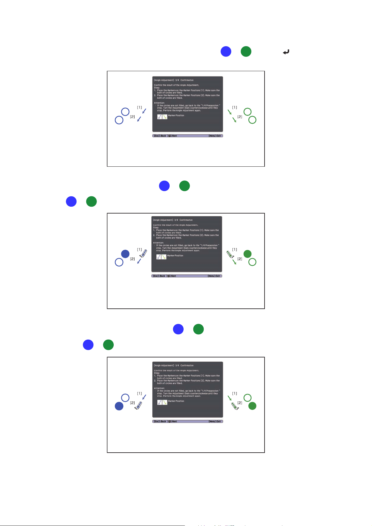
8. When the pointers on the left and right become solid colors ( ) ( ), press the button on the
remote control. The following screen is displayed:
9. Place the markers at the top marker positions [1]. When angle adjustment is performed correctly, the
upper pointers become solid colors ( ) ( ). If the upper pointers do not become solid colors
( ) ( ), start again from step 4.
10. Place the markers at the bottom marker positions [2]. When angle adjustment is performed correctly,
the bottom pointers become solid colors ( ) ( ). If the bottom pointers do not become solid
colors ( ) ( ), start again from step 4.
58
Page 59

11. When you have finished checking the marker positions, remove the markers and press the button
on the remote control. The following confirmation screen is displayed:
12. Trace the dots with your finger as shown. When angle adjustment is performed correctly, the traced
dots disappear.
English
Finger touch operations may not function correctly if you are wearing bandages,
artificial nails, nail polish, or anything else that may obstruct your fingers.
59
Page 60
When all of the dots have disappeared, press the button on the remote control and then go to
step 13.
If any dots remain (as shown below), do the following:
• Remove any obstacles from around the projected screen. When you are finished, press the or
button on the remote control and repeat step 12.
• If the dots still remain after removing obstacles, turn the adjustment dials about a quarter turn
counterclockwise. Next, press the or button on the remote control and repeat step 12.
• If the dots still remain or there are obstacles that cannot be removed, such as whiteboard trays or
frames, go to step 13.
13. If there is an obstacle that cannot be removed, such as a whiteboard tray or frame, remove the tape
from the back of the supplied infrared deflectors and stick them to the screen so that the laser is not
reflected by the obstacle.
Make sure to stick the deflectors between the dots and the obstacle and adjust the number of
deflectors according to the number of dots.
❏ Do not remove an infrared deflector once it has been stuck in place.
❏ Do not stick tape or place anything on the infrared deflectors. The deflectors will
not function properly if anything is placed on them.
After placing the infrared deflectors, press the or button on the remote control, and then
repeat step 12.
If the dots do not disappear even after attaching the infrared deflectors, turn the adjustment dials
about a quarter turn counterclockwise. Next, press the or button on the remote control,
and then repeat step 12 again.
If the dots do not disappear even after performing the above procedures, contact Epson.
60
Page 61

14. Perform touch calibration by pressing Menu on the remote control. On the Extended menu, select
Easy Interactive Function, then Touch Unit Setup. Select Touch Calibration and follow the
instructions.
H Store the markers and attach labels
1. Store the markers inside the Touch Unit.
2. Attach the labels to the tabs on either side of the Touch Unit. Match the centers of the labels with the
tabs on the Touch Unit.
English
If the Touch Unit moves out of position, use the position of the labels to determine
where to reposition the Touch Unit.
I Attach cover
Attach the dial cover. Make sure to tighten the screw at the bottom of the cover.
61
Page 62

9 Installing the Control Pad
You must have completed the steps in “Installing the Projector” on page 30 before installing the Control Pad.
Follow the steps below to install the Control Pad and connect to the projector.
Caution
The Control Pad should only be connected to the BrightLink Pro 1410Wi/1420Wi/1430Wi. Do
not connect the Control Pad to any other projectors.
Check the installation location
The Control Pad must be installed in the area specified in the diagram below.
13.8 in.
78.7 in.
(2.0 m)
68.9 in.
(1.75 m)
35.4 in.
(0.9 m)
27.6 in.
(0.7 m)
(0.35 m)
9.8 in.
(0.25 m)
60-inch
image
Remote control
light emitting areas
100-inch
image
39.3 in. (1.0 m)
59.0 in. (1.5 m)
78.7 in. (2.0 m)
Make sure there is enough space surrounding the Control Pad. Because the top panel
opens from the left, there must be additional space to the left of the Control Pad.
2 in (50 mm)
3.9 in
(100 mm)
2 in (50 mm)
2 in
(50 mm)
62
Page 63

A Remove the cable cover
B Attach the Control Pad
Attach the Control Pad with commercially available M4 × 20 mm screws (×4).
English
Warning
❏ Make sure the screws are not angled.
❏ Make sure the Control Pad is firmly attached.
❏ Do not attach the Control Pad with double-side tape or magnets.
❏ Check that the Control Pad is operating correctly before attaching it with the
screws.
❏ When installing the Control Pad on a table, attach the supplied rubber feet (x4) to
the base of the Control Pad to prevent it from slipping.
63
Page 64

C Install the batteries
Caution
Before handling the batteries, read the safety instructions in your projector’s User’s Guide.
❏ Use two AA manganese or alkaline (recommended) batteries. Do not use any other
type of battery. Rechargable batteries cannot be used.
❏ In order to use the projector to power the Control Pad, connect the optional
Remote control cable set (model ELPKC28, part number V12H005C28) to the
projector’s Remote port and the Control Pad’s Remote port. Do not install
batteries.
D Connect the projector cables to the Control Pad
USB cable 1
Remote control cable
USB cable 2
USB cable 3
USB cable 4
64
USB flash drive
Page 65

To perform the functions listed below, you will need to connect the appropriate cables:
Projector function Required cables
Projecting images from a USB flash drive
Saving data to a USB flash drive
Supplying power from the projector Remote control cable set
Projecting computer images with USB Display or
performing mouse functions using the Easy
Interactive Function
Printing a projected image USB cable 1
E Attach the port protection stickers
Cover the Control Pad ports that are not being used.
F Attach the cable cover
USB cable 1
English
(model ELPKC28; part number
V12H005C28)
USB cable 2
USB cable 3
USB cable 4
65
Page 66

10 Appendix
Using the Easy Interactive Function
After you install your BrightLink model (and the Touch Unit, if applicable), you need to perform calibration to
align the positions of the cursor and your interactive pen(s) (and finger, if the Touch Unit is installed). See the
projector’s online User’s Guide or Start Here folder for detailed instructions.
In order to use the Easy Interactive Tools software, you must first install the software on the computer. OS X
users also need to install a driver that enables pen or finger touch interactivity to work. Both software
programs are included with the BrightLink projector.
For details, see the online User's Guide or visit:
U.S.: epson.com/support/brightlinkdownloads
Canada: epson.ca/support/brightlinkdownloads
Latin America: global.latin.epson.com/Soporte (website available only in Spanish)
Attaching a Security Cable
If the projector is to be installed in a room where it will be left unattended, you can use a commercially
available theft-prevention wire lock to secure the projector to a post or other object to prevent someone from
taking it.
Pass the wire for the theft-prevention wire lock through the security cable installation point.
For details on how to lock the wire lock, refer to the User's Guide supplied with the wire lock.
Make sure you leave the remote control, batteries, CDs, interactive pen(s), pen batteries, pen
tray, and battery charger in the room with the projector. If your projector came with a productspecific installation guide or an installation leave-behind list, use that list instead of this one.
The accessories included with the projector vary by model and region.
66
Page 67

À propos de ce guide d’installation
Le présent guide décrit comment installer les projecteurs à ultra-courte distance de projection listés cidessous sur un mur à l’aide du support de montage Epson® inclus. Il explique aussi comment installer le
boîtier de commande et l’unité tactile après l’installation du support mural.
Ce guide fournit les explications pour les projecteurs suivants :
• BrightLink® 475Wi/480i/485Wi/575Wi/585Wi/595Wi et 575Wi+/585Wi+/595Wi+
• BrightLink Pro 1410Wi/1420Wi/1430Wi
• PowerLite® 470/475W/480/485W/570/575W/580/585W
Consignes de sécurité
Pour votre sécurité, veuillez lire toutes les consignes contenues dans ce guide avant d’utiliser le support de
montage mural. Une manipulation incorrecte ne respectant pas ces consignes pourrait endommager le
support de montage ou provoquer des blessures corporelles ou des dommages matériels. Conservez ce guide
d’installation à portée de main pour pouvoir vous y reporter ultérieurement.
Lisez les consignes de sécurité dans le Guide de l’utilisateur de votre projecteur et suivez les instructions
figurant dans ce document.
Français
Explication des symboles
Les symboles d’avertissement ci-dessous sont utilisés dans ce guide d’installation afin de vous éviter de vous
blesser ou de provoquer des dommages matériels. Assurez-vous de bien avoir compris la signification de ces
avertissements lorsque vous lisez ce guide.
Avertissement
Mise en garde
Ce symbole signale des informations qui, si elles sont ignorées, peuvent provoquer des blessures, voire la
mort, en raison d’une manipulation incorrecte.
Ce symbole indique des informations qui, si elles sont ignorées, peuvent provoquer des blessures ou des
dommages physiques, en raison d’une manipulation incorrecte.
Ce symbole signale des informations connexes ou utiles.
Symbole indiquant une action à ne pas faire
Symbole indiquant une action à faire
Consignes de sécurité pour l’installation
Avertissement
Le support de montage est conçu exclusivement pour fixer un projecteur à un mur. Si un équipement autre
qu’un projecteur est installé, son poids peut endommager le support.
La chute du support de montage peut provoquer des blessures corporelles ou des dommages matériels.
Les travaux d’installation (fixation murale) doivent être effectués par des spécialistes disposant des
compétences techniques et du savoir-faire appropriés. Une installation incomplète ou incorrecte peut
entraîner la chute du support de montage et provoquer des blessures corporelles ou des dommages
matériels.
67
Page 68

Avertissement
Suivez les instructions du présent guide pour installer le support de montage.
En cas de non-respect des instructions, le support de montage peut tomber et provoquer des blessures
corporelles ou des dommages matériels.
Suivez les instructions du présent guide pour installer et utiliser l’unité tactile.
Si l’unité tactile n’est pas installée et utilisée de façon appropriée, la lumière émise par le laser pourrait entraîner
des lésions oculaires.
Manipulez le cordon d’alimentation avec précaution.
Une manipulation incorrecte peut provoquer un incendie ou une électrocution. Prenez les précautions suivantes
en le manipulant :
• Ne saisissez pas la fiche secteur avec des mains humides.
• N’utilisez pas un cordon d’alimentation endommagé ou modifié.
• Ne tirez pas exagérément sur le cordon lorsque vous le faites passer à travers le support de montage.
N’installez pas le support de montage à un endroit où il peut être soumis à des vibrations ou des chocs.
Des vibrations ou des chocs pourraient endommager le projecteur ou la surface de montage. Vous risqueriez
également de provoquer la chute du support de montage ou du projecteur et donc provoquer des blessures
corporelles ou des dommages matériels.
L’installation doit être exécutée par au moins deux techniciens qualifiés. Si vous devez desserrer des vis
pendant l’installation, veillez à ne pas provoquer la chute du support de montage.
La chute du support de montage ou du projecteur peut provoquer des blessures corporelles ou des dommages
matériels.
Installez le support de montage de sorte qu’il puisse supporter son poids ainsi que celui du projecteur et
résister à toute vibration horizontale. Utilisez des écrous et des boulons M10 et assurez-vous d’utiliser les
pattes de fixation murales appropriées pour votre type de mur.
Si vous utilisez des écrous et des boulons de taille inférieure à M10, le support de montage risque de tomber.
Epson n’accepte aucune responsabilité pour tout dommage ou toute blessure dus à une solidité du mur
insuffisante ou une installation inappropriée.
La fixation du projecteur sur un mur à l’aide du support de montage doit être effectuée sur un mur
suffisamment solide pour maintenir le projecteur, le support de montage, ainsi que le boîtier de
commande et l’unité tactile, au besoin.
Ce support de montage doit être installé sur un mur en béton. Vérifiez donc le poids du projecteur, du
support de montage, du boîtier de commande et de l’unité tactile avant l’installation et veillez à la bonne
solidité du mur. Si la solidité du mur est insuffisante, renforcez le mur avant de procéder à l’installation.
Inspectez régulièrement le support de montage pour vérifier qu’aucune de ses pièces n’est endommagée
ou que des vis ne sont pas desserrées.
Si des pièces sont endommagées, cessez immédiatement d’utiliser le support de montage. La chute du support de
montage ou du projecteur peut provoquer des blessures corporelles ou des dommages matériels.
Ne modifiez jamais le support de montage, le boîtier de commande ou l’unité tactile.
Ne suspendez aucun objet au support de montage ni ne posez d’objet lourd sur celui-ci.
La chute du support de montage ou du projecteur peut provoquer des blessures corporelles ou des dommages
matériels.
N’utilisez pas d’adhésifs, ni d’huiles ou de lubrifiants pour installer ou régler le support de montage.
Si vous utilisez des adhésifs pour empêcher les vis de se desserrer ou si vous utilisez des lubrifiants ou des huiles
sur la partie du projecteur fixée à la plaque coulissante, le boîtier risque de se détériorer, et risque de provoquer la
chute du projecteur et des blessures corporelles ou des dommages matériels.
Serrez fermement toutes les vis après tout réglage.
Sinon, le support de montage ou le projecteur pourrait tomber et provoquer des blessures corporelles ou des
dommages matériels.
Ne desserrez jamais les écrous et les boulons après l’installation.
Vérifiez régulièrement que les vis ne se sont pas desserrées. Si vous constatez le moindre jeu, resserrez fermement
les vis concernées. Sinon, le support de montage ou le projecteur pourrait tomber et provoquer des blessures
corporelles ou des dommages matériels.
68
Page 69

Avertissement
Lorsque vous effectuez le câblage, assurez-vous que les câbles n’entrent pas en contact avec les vis ou les
écrous.
La manipulation incorrecte des câbles peut provoquer un incendie ou un choc électrique.
N’appliquez pas d’appareils optiques tels qu’une loupe ou un télescope à la lumière laser diffusée depuis
l’unité tactile.
L'utilisation d'appareils optiques dans ces conditions pourrait entraîner des blessures ou un incendie.
Ne regardez pas dans les ports de diffusion laser de l’unité tactile.
Cela pourrait entraîner des problèmes oculaires. Veuillez prêter une attention particulière lorsque des enfants sont
présents.
Ne regardez pas la lumière laser en utilisant des appareils optiques tels qu’une loupe à moins de 2,75 po
(70 mm).
Le visionnement à portée réduite peut entraîner des problèmes oculaires.
Connectez l’unité tactile aux modèles BrightLink 595Wi/595Wi+ et BrightLink Pro 1430Wi seulement. Ne
connectez pas l’unité à d’autres projecteurs ou appareils.
N’utilisez pas l’unité tactile si vous utilisez ou êtes à proximité d’équipement médical tel qu’un stimulateur
cardiaque.
L’aimant de l’unité tactile génère de l’interférence électromagnétique qui pourrait entraîner une défaillance de
l’équipement médical.
Mise en garde
Français
N’installez pas le support de montage dans un endroit qui excède la plage de température de
fonctionnement du modèle de projecteur. Un tel environnement peut endommager le projecteur.
Installez le support de montage dans un endroit à l’abri de la poussière et de l’humidité pour que l’objectif
et les éléments optiques internes ne se salissent pas.
Ne forcez pas de manière excessive lorsque vous réglez le support de montage.
Le support de montage peut être endommagé et provoquer des blessures corporelles.
Conservez les appareils de stockage magnétiques (par exemple, les cartes magnétiques ou les appareils
électroniques tels que les ordinateurs, les montres à affichage numérique ou les téléphones cellulaires)
loin de l’unité tactile.
L’aimant à l’intérieur de l’unité tactile génère de l’interférence magnétique qui pourrait corrompre les données ou
entraîner un mauvais fonctionnement des appareils ou supports.
Emplacement pour l’installation
• Avant d’installer le projecteur, vérifiez le câblage de l’alimentation électrique de l’emplacement
d’installation.
• Éloignez le projecteur des autres appareils électriques, notamment des éclairages fluorescents ou des
climatiseurs. Certains types d’éclairages fluorescents risquent d’interférer avec la télécommande du
projecteur.
• Assurez-vous que le projecteur n’est pas directement exposé à la lumière du soleil ou d’autres sources de
lumière vive.
• Nous vous recommandons d’utiliser un câble d’ordinateur VGA d’une longueur inférieure à 20 mètres
(65 pieds) afin de réduire l’effet de parasites.
• Installez le projecteur dans un emplacement où l’image projetée est à votre portée.
• Le projecteur doit être installé dans l’un des emplacements suivants afin que l’unité tactile puisse
fonctionner correctement :
• Monté à un mur ou suspendu au plafond avec la projection d’images depuis l’avant de l’écran.
69
Page 70

• Monté verticalement sur une table avec la projection d’images depuis le devant de la table. Si vous
utilisez cette méthode d’installation, vous aurez besoin du support pour table interactive en option
(ELPMB29) et de la plaque de fixation (ELPPT05).
• Lorsque le boîtier de commande est alimenté par des piles, suivez les directives suivantes lors de
l’installation :
• Installez le boîtier de commande sur la même surface que l’écran de projection. Si l’écran de
projection et le point d’installation du boîtier de commande ne sont pas au même niveau, installez le
boîtier de commande à environ 20 cm (8 po) du bord de l’écran.
• Assurez-vous qu’il n’y a aucun objet bloquant le signal entre le boîtier de commande et le projecteur
(à l’exception de l’unité tactile).
• Utilisez l’ensemble de câbles de la télécommande optionnel (modèle ELPKC28, numéro de pièce
V12H005C28) pour alimenter le boîtier de commande lors des situations suivantes :
• Les directives mentionnées ci-dessus ne peuvent pas être suivies.
• L’écran de projection et le point d’installation du boîtier de commande ne sont pas au même niveau
et la différence de hauteur est de plus de 2 po (5 cm).
• Le projecteur est placé sur une table et il projette vers l’écran.
• Plusieurs projecteurs sont utilisés.
• Avant d’installer l’unité tactile, vérifiez si l’emplacement pour l’installation répond aux critères suivants :
• L’unité tactile peut être fixée à la surface avec des aimants ou des vis.
• La surface est plate, lisse et régulière avec moins de 5 mm (0,2 po) d’inégalité (dans toutes les
directions) sur la surface de l’écran.
5 mm (0,2 po)
• Lors de l’installation sur un tableau blanc, installez l’unité tactile à l’intérieur du cadre du tableau
blanc.
Position correcte Position incorrecte
70
Page 71

• Assurez-vous qu’il n’y a pas d’obstacles, par exemple des câbles ou des objets protubérants comme des
plateaux pour tableau blanc ou des cadres épais dans les zones ombrées de l’illustration ci-dessous.
L’unité tactile ne fonctionnera pas correctement si le signal infrarouge est bloqué.
100 mm (4,0 po)100 mm (4,0 po)
20 mm (0,8 po)
Français
71
Page 72

1 Contenu de l’emballage
s 75
2 Spécifications
3 Connexion des appareils
4 Positionnement du projecteur
1. Feuille de travail d’installation pour la projection sur un tableau mural
préinstallé
2. Feuille de travail d’installation pour la projection sur un mur ordinaire
3. Taille de l’image diagonale et position de montage
4. Distance de la surface de projection à la plaque murale
5. Mesures d’installation en pouces pour les projecteurs WXGA
6. Mesures d’installation en pouces pour les projecteurs XGA
7. Mesures d’installation en millimètres pour les projecteurs WXGA
8. Mesures d’installation en millimètres pour les projecteurs XGA
5 Installation du projecteur
1. Désassemblez les pièces
s 77
s 80
s 83
s 103
2. Assemblez les pièces
3. Installez la plaque murale sur le mur
4. Déterminez la distance de projection et retirez la glissière
5. Faites passer les câbles dans le bras du support de montage
6. Fixez le bras du support de montage à la plaque murale
7. Réglez la position du coulissement vertical du bras
8. Fixez le projecteur au support de montage
9. Connectez le cordon d’alimentation et les autres câbles au projecteur
72
Page 73

6 Réglage de l’image
1. Mettez le projecteur sous tension
2. Affichez la mire
3. Changez le rapport hauteur/largeur (au besoin)
4. Réglez la mise au point
5. Utilisez la poignée de réglage sur le côté gauche pour régler le roulis horizontal
6. Utilisez la poignée de réglage sur le côté droit pour régler la rotation
horizontale
7. Utilisez la poignée de réglage dans le haut pour régler l’inclinaison verticale
8. Réglez le coulissement horizontal
9. Réglez le coulissement vers l’avant/l’arrière
10. Réglez le coulissement vertical
11. Supprimez l’affichage de la mire
s 114
Français
7 Fixation des caches
1. Fixez le cache du support de montage et le capuchon de protection
2. Fixez le cache du câble au projecteur
8 Installation de l’unité tactile
1. Mettez le projecteur sous tension
2. Affichez le motif d’installation
3. Retirez les marqueurs
4. Déterminez la position d’installation de l’unité tactile
5. Installez l’unité tactile
6. Branchez le câble
7. Réglez l’angle
8. Stockez les marqueurs et posez les étiquettes
9. Posez le couvercle
9 Installation du boîtier de commande
1. Retirez le cache-câbles
s 121
s 123
s 136
2. Fixez le boîtier de commande
3. Installez les piles
4. Connectez les câbles du projecteur au boîtier de commande
5. Apposez les autocollants de protection de port
6. Fixez le cache-câbles
10 Annexe
1. Pour la fonction Easy Interactive
2. Fixation d’un câble de sécurité
s 140
73
Page 74

74
Page 75

1 Contenu de l’emballage
Support de montage
Support de montage
Français
Arbre hexagonal
Dispositif de réglage à 3 axes et
plaque coulissante (fixés à la
livraison)
Câble d’ordinateur VGA (peut être
inclus avec le projecteur ou le support
de montage)
Plaque murale
Rallonge du capot de la
plaque murale
Clé plate
13 mm (pour M8 et M6) x
6 mm (pour arbre
hexagonal)
Cache de la plaque murale
(pour l’installation de la plaque murale)
Clé à six pans (pour M4)
Fiche modèle
Capuchon de
protection
Forme Nom Quantité Application
Boulon à tête cylindrique à six pans M4 x 12 mm
avec rondelle/rondelle élastique
Boulon à épaulement à six pans M6 x 20 mm avec
rondelle/rondelle élastique
Vis à épaulement à tête à empreinte cruciforme
M6 x 20 mm avec rondelle plastique
6 Pour l’assemblage de la plaque murale
4 Pour l’installation du dispositif de
réglage à 3 axes/support de montage
4 Pour l’installation de la plaque
coulissante/du projecteur
2 Pour l’installation de la plaque
coulissante/du dispositif de réglage à
3 axes (fixés ensemble à la livraison)
1 Pour l’installation du support de
montage/plaque murale
3
• Utilisez les vis ou les boulons fournis avec le support de montage pour installer ce dernier, comme décrit
dans le présent guide. Ne leur substituez pas un autre type de boulons.
75
Page 76
• Vous devez aussi utiliser des pattes de fixation M10 x 60 mm disponibles en magasin (au moins 3) pour
fixer la plaque murale au mur.
• Rassemblez les outils et les éléments nécessaires avant de commencer l’installation, incluant un tournevis
cruciforme numéro 3.
Unité tactile
Les pièces suivantes sont emballées avec votre projecteur et sont nécessaires lors de l’installation de l’unité
tactile. Lorsque vous installez l’unité tactile sur une surface non magnétique, vous aurez aussi besoin de
vis M4.
Rondelle d’espacement pour trou de
Unité tactile et marqueurs
(les marqueurs sont à l’intérieur de l’unité)
vis (×3)
Câble de connexion
pour unité tactile
Étiquettes (×4)
Ruban adhésif (approx.
6cm[2,4po]) pour fixer
les marqueurs ×12
Déflecteurs infrarouges
(approx. 28,5 cm [11,2 po]) ×8
Boîtier de commande
Les pièces suivantes sont emballées avec votre projecteur et elles sont requises pour fixer le boîtier de
commande. Lorsque vous installez le boîtier de commande sur un mur, vous aurez aussi besoin de quatre
vis M4 x 20 mm.
Piles de format AA (x 2) Autocollants de
Boîtier de commande
Pieds en
plastique
protection de port
76
Page 77

2Spécifications
Élément Spécification Information supplémentaire Page de
Hauteur du support de montage
(incluant le dispositif de réglage à
3 axes, la plaque coulissante, la
plaque murale, le cache de la
plaque murale, la rallonge du
capot de la plaque murale et le
bouchon de protection)
Capacité de chargement
maximale
Plage de réglage du coulissement
vertical
Plage de réglage du coulissement
horizontal
Plage de réglage du coulissement
vers l’avant/l’arrière
Plage de réglage du roulis
horizontal
Plage de réglage de la rotation
horizontale
Plage de réglage de l’inclinaison
verticale
Environ 8,4 kg
(18,5 lb)
7 kg (15,4 lb) — —
38 mm (± 1,5 po) — Voir
45 mm (± 1,8 po) — Voir
360 mm
(0 à 14,2 po)
± 3° Réglages précis possibles avec la poignée de réglage
± 8° Réglages précis possibles avec la poignée de réglage
± 3° Réglages précis possibles avec la poignée de réglage
Support de montage : 3,0 kg (6,6 lb)
Dispositif de réglage à 3 axes : 1,2 kg (2,6 lb)
Plaque coulissante : 0,8 kg (1,8 lb)
Plaque murale : 2,7 kg (6,0 lb)
Cache de la plaque murale et capuchon de protection :
0,4 kg (0,9 lb)
Rallonge du capot de la plaque murale : 0,3 kg (0,6 lb)
Plage de réglage du coulissement du bras : 0 à 273 mm
(0 à 10,7 po)
Réglage à partir de la position d’installation du
dispositif de réglage à 3 axes : 87 mm (3,4 po)
référence
—
l’illustration
ci-dessous
l’illustration à
la page
suivante
Voir
l’illustration à
la page
suivante
s p. 117
s p. 118
s p. 118
Français
Plaque murale
La plaque murale est livrée en trois pièces. Utilisez les boulons M4 x 12 mm (x6) inclus pour fixer les pièces
séparées avant le montage du projecteur. Consultez la page 104 pour obtenir les instructions.
130 mm
(5,1 po)
25 mm
(1,0 po)
80 mm
(3,2 po)
30,6 mm
(1,2 po)
106,5 mm
(4,2 po)
60 mm)
(2,4 po)
117 mm (4,6 po)
223 mm (8,8 po)
496 mm (19,5 po)
79 mm
(3,1po)
160 mm (6,3 po)
33 mm
(1,3 po)
246 mm (9,7 po)
222 mm (8,7 po)
213 mm (8,4 po)
77
Page 78

Plage de réglage du coulissement vertical
38 mm (1,5 po)
38 mm (1,5 po)
Plage de réglage du coulissement horizontal
45 mm (1,8 po)
45 mm (1,8 po)
Plage de réglage du coulissement vers l’avant/l’arrière
Plage de réglage du coulissement du bras
273 mm (10,7 po)
Réglage à partir de la position d’installation du dispositif de réglage à 3 axes
En déplaçant la position d’installation du dispositif de réglage à 3 axes vers l’avant ou l’arrière, vous pouvez
régler la position d’installation du projecteur.
Lorsque la taille de l’écran est inférieure à 75 pouces (190,5 cm), installez-le à la position indiquée par le
poinçon sur le bras de montage.
Lorsque la taille de l’écran est de 75 pouces (190,5 cm) ou plus, installez-le à la position indiquée par le
poinçon sur le bras de montage.
78
Page 79

Pour voir le poinçon, vous devez retirer les deux vis placées dans le haut et ensuite, faire glisser la rallonge
du bras.
Poinçon
Poinçon
87 mm (3,4 po)
Unité tactile
Dimensions externes et poids
L’unité tactile pèse environ 450 g (16 oz).
Français
95 mm (3,7 po)
210 mm (8,3 po)
51 mm
(2,0 mm)
Étiquettes d’avertissement
L’unité tactile est un produit laser de classe 1 qui est conforme à la norme JIS C 6802:2011. Des étiquettes
d’avertissement sont apposées à l’unité tactile afin d’indiquer qu’il s’agit d’un produit laser de classe 1. Les
étiquettes contiennent les informations suivantes :
• Radiations laser invisibles
• Évitez de regarder le faisceau laser directement avec des instruments optiques
• Produit laser classe 1
79
Page 80

Port de diffusion du laser
Le faisceau laser est diffusé depuis les ports de diffusion laser à l’arrière de l’unité tactile.
Ports de diffusion laser
Boîtier de commande
Dimensions externes et poids
Le boîtier de commande pèse environ 240 g (8,5 oz).
111 mm (4,4 po)
135,9 mm (5,4 po)
11,5 mm
(0,4 po)
109 mm (4,3 po)
3,5 mm (0,1 po)
149 mm (5,9 po)
153,5 mm (6,0 po)
107 mm (4,2 po)
104 mm (4,0 po)
(0,6 po)
15,47 mm
29 mm
(1,2 po)
(1,1 po)
30,9 mm
Trous pour le passage des câbles
Lorsque vous faites passer les câbles à travers un mur, utilisez la position ( ) dans l’illustration suivante
comme trou pour le passage des câbles.
80
Page 81

Sinon, retirez le cache-câbles ( ) et faites passer les câbles à travers l’ouverture. Faites passer le câble de
l’imprimante le long de la rainure à l’arrière du boîtier de commande
Français
81
Page 82

3 Connexion des appareils
Assurez-vous d’avoir le cordon d’alimentation, le câble d’ordinateur et les autres pièces à l’emplacement
d’installation du support de montage.
Assurez-vous aussi d’avoir tous les câbles nécessaires pour l’unité tactile et tous les appareils que vous envisagez
de connecter au projecteur, par exemple, une caméra de documents ou un microphone. Il est possible que le
panneau de connexion soit différent de celui du modèle illustré. Pour obtenir plus de détails, consultez le Guide
de l’utilisateur en ligne pour votre projecteur.
Exemple de connexion
Haut-parleurs externes
Câble audio
(non inclus)
Microphone
Caméra de
documents
(Epson DC-06)
Câble de connexion
pour unité tactile
Appareil réseau local
Unité tactile
Câble réseau local
(non inclus)
Câble d’ordinateur
(pour la sortie vidéo de
l’ordinateur)
Ordinateur
Câble USB (pour la
fonction Easy Interactive)
82
Câble USB dédié
(fourni avec la caméra de documents)
Page 83

Pour la fonction interactive
Lorsque vous interagissez avec l’image projetée via une connexion à un ordinateur, un câble
USB est nécessaire. Vous n’avez cependant pas besoin d’un câble USB lorsque vous interagissez
avec l’image projetée à l’aide de la fonction intégrée du projecteur.
Connexion du boîtier de commande
Le boîtier de commande est inclus avec les projecteurs BrightLink Pro 1410Wi/1420Wi/1430Wi. Il offre une
autre option que la télécommande pour mettre le projecteur sous tension, changer la source et sélectionner
le mode de tableau blanc. Vous pouvez aussi utiliser le boîtier de commande pour saisir, imprimer et
enregistrer les images projetées.
Vous devez installer le boîtier de commande sur la même surface que le projecteur à l’intérieur de la zone de
couverture spécifiée dans les instructions d’installation. Vous pouvez utiliser les piles incluses ou l’ensemble
de câbles de la télécommande (modèle ELPKC28, numéro de pièce V12H005C28) pour alimenter le boîtier de
commande.
Consultez la section Installation du boîtier de commande p. 136 pour les instructions.
4 Positionnement du projecteur
Les projecteurs BrightLink Pro 1410Wi/1420Wi/1430Wi, BrightLink 475W/485W, BrightLink 575Wi/585Wi/
595Wi, BrightLink 575Wi+/585Wi+/595Wi+ et les projecteurs PowerLite 475W/485W/575W/585W peuvent
projeter jusqu’à 254 cm (100 po) diagonalement pour une image WXGA, ou 223,5 cm (88 po) diagonalement
pour une image XGA. Les projecteurs BrightLink 480i et PowerLite 470/480/570/580 peuvent projeter jusqu’à
236 cm (93 po) diagonalement pour une image XGA.
Français
Vous pouvez projeter sur un tableau blanc préinstallé ou directement sur un mur ordinaire. Lors de
l’installation de l’unité tactile, veillez à installer l’unité sur l’écran qui est utilisé pour la projection; il doit y avoir
une distance d’au moins 120 mm (4,7 po) entre le bord supérieur de l’image projetée et le bord supérieur de
l’écran. C’est la hauteur du support mural qui détermine la taille d’image maximum et la hauteur à laquelle
l’image est projetée sur le mur ou le tableau blanc. La distance entre le mur et le projecteur (une fois qu’il est
monté sur le bras réglable du support de montage) influe aussi sur la taille et la position de l’image.
Si vous planifiez de projeter sur un tableau blanc, il est possible que l’image n’occupe pas tout le tableau; tout
dépend du rapport hauteur/largeur. Si vous faites correspondre la hauteur de l’image à la hauteur du tableau,
il est possible que des espaces apparaissent sur les côtés du tableau.
83
Page 84

Utilisez les feuilles de travail suivantes pour déterminer l’emplacement approprié de la plaque murale sur le
mur. Si vous projetez sur un tableau blanc préinstallé, utilisez la feuille de travail à la page suivante. Si vous
projetez sur un mur ordinaire, utilisez la feuille de travail de la page 86.
Lors de l’installation sur un tableau blanc, assurez-vous de laisser les écarts suivants
autour du bord du tableau :
❏ Du bord supérieur de l’image projetée jusqu’au bas de l’unité tactile : 25 mm (1 po)
❏ Des bords de l’image projetée jusqu’aux bords du tableau : au moins 100 mm (4 po)
à gauche et à droite
❏ Du bas de l’image projetée jusqu’au bas du tableau : 20 mm (0,8 mm)
S’il y a des obstacles tels que des câbles, des plateaux pour tableau blanc, des plateaux
pour crayon ou des cadres dans les zones mentionnées ci-dessus, l’unité tactile ne
fonctionnera pas correctement.
84
Page 85

Feuille de travail d’installation pour la projection sur un tableau mural préinstallé
1. Mesurez la hauteur du plafond (distance du plancher au plafond). _____
2. Mesurez la hauteur de la zone d’image du tableau (h). _____ (h)
3. Mesurez la largeur de la zone d’image du tableau (l). _____ (l)
4. Mesurez la distance du plancher au bas de la zone d’image du tableau (f). _____ (f )
5. Mesurez la distance du plafond au sommet de la zone d’image du tableau (d). _____ (d)
6. Mesurez l’épaisseur du tableau (la distance de la surface de projection au mur) (x). _____ (x)
Français
254 mm (10 po) — hauteur de la
plaque murale avec le cache
Distance requise du sommet de
la zone d’image aux trous dans
le bas de la plaque murale (c)
Hauteur de la
zone d’image (h)
20 mm (0,8 po) — distance
du bas de la zone d’image
au bas du tableau
25 mm (1 po) — distance du
sommet de la zone d’image au bas
de l’unité tactile
Taille diagonale de
la zone d’image (s)
Largeur de la zone d’image (l)
Distance du plancher au bas de
la zone d’image (f)
Distance du plafond au haut de
la zone d’image (d)
119 mm (4,7 po) —
distance du sommet
de la zone d’image au
sommet du tableau
100 mm (4 po) —
distance du bord de la
zone d’image au bord
du tableau
7. Déterminez le rapport hauteur/largeur du tableau ou des images à projeter. Pour de
nouveaux ordinateurs ou portatifs, il s’agira probablement de WXGA (16:10). Pour
l’équipement plus ancien, il s’agira probablement de XGA (4:3). Il vous faudra peutêtre consulter le service des TI pour obtenir cette information.
___ 4:3 XGA ___ 16:10 WXGA ___ 16:9 grand écran
8. En utilisant les tableaux des pages 90 à 96 pour votre rapport hauteur/largeur et la
hauteur d’image souhaitée (h), trouvez la distance requise entre le sommet de la zone
d’image et les trous dans le bas de la plaque murale (c).
9. Déterminez la position pour l’installation de votre projecteur en additionnant les
valeurs (f), (h) et (c), en prévoyant 254 mm (10 po) de plus pour la hauteur de la
plaque murale et le cache.
Si la hauteur du plafond de votre salle (telle que notée à l’étape 1) ne correspond pas
à la hauteur de plafond minimum requise pour votre tableau, vous pourriez avoir
besoin de sélectionner une taille d’image plus petite ou d’abaisser le tableau sur le
mur.
10. Après avoir confirmé votre taille d’image, utilisez du ruban ou un crayon pour
marquer la distance (c) du sommet de la zone d’image sur le tableau aux trous dans le
bas de la plaque murale.
85
_____ (c)
_____ (f)
_____ (h)
_____ (c)
+10
po
(254 mm)
_____ total
Page 86

11. Alignez la ligne horizontale sur le gabarit avec la marque (c), puis alignez la ligne
centrale du gabarit avec le centre de la zone d’image. Suivez les directives de la page
103 pour installer le projecteur.
Feuille de travail d’installation pour la projection sur un mur ordinaire
1. Mesurez la hauteur du plafond (distance du plancher au plafond). _____
2. Déterminez le rapport hauteur/largeur souhaité de l’image. Pour de nouveaux
ordinateurs ou portatifs, il s’agira probablement de WXGA (16:10). Pour l’équipement
plus ancien, il s’agira probablement de XGA (4:3). Il vous faudra peut-être consulter
votre service des TI pour obtenir cette information.
___ 4:3 XGA ___ 16:10 WXGA ___ 16:9 grand écran
3. À l’aide des tableaux des pages 90 à 96 pour votre rapport hauteur/largeur,
sélectionnez la taille d’image la plus grande qui soit disponible pour la hauteur de
votre plafond.
Hauteur de l’image (h)
Largeur de l’image (l)
_____ (h)
_____ (l)
4. Mesurez la distance souhaitée du plancher au bas de la zone d’image (f).
La distance minimum recommandée est de 762 mm (30 po). Il se peut que la vue des
images apparaissant à moins de 28 pouces du plancher soit obstruée.
5. Trouvez le sommet de la zone d’image projetée en additionnant les distances (f) et
(h).
6. Utilisez les tableaux des pages 90 à 96 pour déterminer la distance requise du haut de
la zone d’image aux trous dans le bas de la plaque murale (b). _____ (c)
7. Additionnez :
Distance requise du sommet de la zone d’image aux trous dans le bas de la plaque
murale (c)
Hauteur de la zone d’image (h)
Distance du plancher au bas de la zone d’image (f)
Hauteur de la plaque murale avec le cache
Si le total dépasse la hauteur du plancher, il vous faudra réduire la taille d’image ou
réduire la distance du plancher au bas de la zone d’image.
_____ (f)
_____
_____ (c)
_____ (h)
_____ (f)
+10
po
(254 mm)
_____ total
86
Page 87

Hauteur de
plafond
254 mm (10 po) — hauteur
de la plaque murale avec
le cache
Distance requise du sommet de
la zone d’image aux trous dans le
bas de la plaque murale (c)
25 mm (1 po) — distance du
sommet de la zone d’image au
bas de l’unité tactile
Hauteur de la
zone d’image (h)
Largeur de la zone d’image (l)
Distance du plafond au
haut de la zone
d’image (d)
Taille diagonale
de l’image (s)
Distance du plancher au bas
de la zone d’image (f)
Français
8. Après avoir confirmé votre taille d’image, utilisez du ruban ou un crayon pour
marquer la distance (c) du sommet de la zone d’image sur le tableau aux trous dans le
bas de la plaque murale.
9. Alignez la ligne horizontale sur le gabarit avec la marque (c), puis alignez la ligne
centrale du gabarit avec le centre de la zone d’image. Suivez les directives de la page
103 pour installer le projecteur.
Les tableaux des pages suivantes fournissent des renseignements d’installation pour toutes les tailles d’image
prises en charge. La hauteur de plafond minimum est basée sur une image à 762 mm (30 po) du plancher; si
l’image est plus basse, la hauteur de plafond minimum est réduite par la mesure correspondante.
Utilisez les feuilles de travail, les illustrations et les renseignements des tableaux aux pages suivantes pour
déterminer la distance de projection et le placement de la plaque murale. L’intervalle recommandé pour la
distance de projection (a) tel qu’illustré aux pages suivantes est de 62 à 311 mm (2,5 po à 12,2 po).
Taille de l’image diagonale et position de montage
Les chiffres sur la mesure de la glissière (b) sont les mêmes que ceux de la distance de projection (a) lorsque la
taille de l’image diagonale (S) est de 75 po (190,5 cm) ou plus. Parce que la position d’installation du projecteur
change lorsque (S) est moins de 75 po (190,5 cm), les chiffres pour (a) et (b) sont différents.
87
Page 88

Décalage pour la position du centre de
l’écran et le centre de la plaque murale
218 mm
(8,6 po)
70,5 mm (2,8 po)
120 mm (4,7 po)
Plaque murale
30,6 mm (1,2 po)
Hauteur
de l’image
projetée
100 mm (4 po)
Distance du mur à la surface
de projection
20 mm (0,8 po)
25 mm (1 po)
Surface de
projection
Pour voir le poinçon et les chiffres sur le coulissement de la glissière, vous devez faire glisser la rallonge du
bras.
Lorsque la taille de l’image diagonale est de 75 po (190,5 cm) ou plus, montez le dispositif de réglage à 3 axes
à la position indiquée avec le poinçon .
Lorsque la taille de l’image diagonale est de moins de 75 po (190,5 cm), montez le dispositif de réglage à 3
axes à la position indiquée avec le poinçon .
88
Page 89

Distance de la surface de projection à la plaque murale
La distance (c) entre l’écran de projection et les trous dans le bas de la plaque murale correspond au chiffre
indiqué lorsque le coulissement vertical est à la position de base, tel qu’illustré ci-dessous.
Alignez l’encoche sur la plaque d’installation avec la position du poinçon sur la plaque murale.
Position de base
Poinçon sur la plaque
Encoche sur le bras du support
Tableaux des mesures d’installation
Utilisez le tableau suivant afin de déterminer quel tableau de mesures vous devez utiliser pour votre
projecteur.
Français
Modèle du projecteur Taille de l’image
maximale
(diagonale)
BrightLink Pro 1410Wi/1420Wi/1430Wi
BrightLink 475W/485W/575Wi/585Wi/595Wi
100 WXGA
BrightLink 575Wi+/585Wi+/595Wi+
PowerLite 475W/485W/575W/585W
BrightLink 480i
93 XGA
PowerLite 470/480/570/580
Tableau des
mesures
d’installation
Les mesures peuvent varier selon l’emplacement choisi pour le projecteur.
Lors d’une projection en mode Télé, la qualité des images projetées peut être réduite.
Lorsqu’un projecteur WXGA est utilisé pour projeter des images à un rapport largeur/
hauteur 4:3, les images sont automatiquement redimensionnées et la qualité des
images projetées peut être réduite.
Lorsque la rallonge du capot de la plaque murale est installée, la taille de l’image
diagonale minimale est augmentée à : WXGA 67 po (16:10), 65 po (16:9), 59 po (4:3);
XGA 62 po (4:3), 57po (16:9), 59 po (16:10).
89
Page 90

haut de
Dist. du
de
Repères
proj.
Dist. de
de
Hauteur
de
Largeur
du
Hauteur
haut de
Dist. du
de
Repères
aux
l’image
(b)
glissière
min. (a)
(h)
l’image
(l)
l’image
min.*
plafond
l’image
aux trous
(b)
glissière
la
trous de
de la
plaque
(c)
plaque
murale
murale(c)
proj.
min. (a)
Dist. de
de
(h)
l’image
Hauteur
(l)
de
l’image
Largeur
du
min.*
plafond
Hauteur
la
aux
l’image
haut de
Dist. du
de
(b)
Repères
glissière
proj.
min. (a)
Dist. de
16:10 WXGA 4:3 XGA 16:9 grand écran
de
(h)
l’image
Hauteur
(l)
de
l’image
Largeur
trous de
plaque
murale
78,7 42,4 31,8 2,5 5,9 6,9 — — — — — —
79,4 43,2 32,4 2,7 6,1 7,0 — — — — — —
80,1 44,0 33,0 3,0 6,4 7,1 — — — — — —
80,8 44,8 33,6 3,3 6,7 7,2 — — — — — —
81,5 45,6 34,2 3,6 7,0 7,3 — — — — — —
82,3 46,4 34,8 3,8 7,3 7,5 — — — — — —
83,0 47,2 35,4 4,1 7,6 7,6 77,5 51,4 28,9 2,6 6,0 8,5
(c)
Mesures d’installation en pouces pour les projecteurs WXGA
Hauteur
l’image
Taille de
du
min.*
plafond
(S)
diagonale
54 po ——————
53 po ——————
55 po ——————
56 po ——————
57 po ——————
58 po ——————
78,7 50,9 31,8 2,5 5,9 6,9 83,7 48,0 36,0 4,4 7,8 7,7 78,1 52,3 29,4 2,9 6,3 8,7
60 po
59 po ——————
79,3 51,7 32,3 2,7 6,1 7,0 84,4 48,8 36,6 4,7 8,1 7,8 78,7 53,2 29,9 3,1 6,5 8,8
61 po
79,9 52,6 32,9 3,0 6,4 7,1 85,1 49,6 37,2 5,0 8,4 7,9 79,3 54,0 30,4 3,4 6,8 8,9
62 po
80,6 53,4 33,4 3,2 6,6 7,2 85,8 50,4 37,8 5,2 8,7 8,0 80,0 54,9 30,9 3,6 7,0 9,1
63 po
81,2 54,3 33,9 3,4 6,9 7,3 86,6 51,2 38,4 5,5 8,9 8,2 80,6 55,8 31,4 3,9 7,3 9,2
64 po
81,8 55,1 34,4 3,7 7,1 7,4 87,3 52,0 39,0 5,8 9,2 8,3 81,2 56,7 31,9 4,1 7,6 9,3
65 po
82,5 56,0 35,0 3,9 7,4 7,5 88,0 52,8 39,6 6,1 9,5 8,4 81,8 57,5 32,4 4,4 7,8 9,5
83,1 56,8 35,5 4,2 7,6 7,6 88,7 53,6 40,2 6,3 9,8 8,5 82,5 58,4 32,9 4,6 8,0 9,6
66 po
67 po
83,7 57,7 36,0 4,4 7,8 7,7 89,4 54,4 40,8 6,6 10,0 8,6 83,1 59,3 33,3 4,9 8,3 9,7
68 po
84,4 58,5 36,6 4,7 8,1 7,8 90,2 55,2 41,4 6,9 10,3 8,8 83,7 60,1 33,8 5,1 8,5 9,9
69 po
85,0 59,4 37,1 4,9 8,3 7,9 90,9 56,0 42,0 7,2 10,6 8,9 84,3 61,0 34,3 5,4 8,8 10,0
70 po
85,6 60,2 37,6 5,1 8,6 8,0 91,6 56,8 42,6 7,4 10,9 9,0 85,0 61,9 34,8 5,6 9,1 10,2
71 po
72 po 86,3 61,1 38,2 5,4 8,8 8,1 92,3 57,6 43,2 7,7 11,1 9,1 85,6 62,8 35,3 5,9 9,3 10,3
90
Page 91

haut de
Dist. du
de
Repères
proj.
Dist. de
de
Hauteur
de
Largeur
du
Hauteur
haut de
Dist. du
de
Repères
aux
l’image
(b)
glissière
min. (a)
(h)
l’image
(l)
l’image
min.*
plafond
l’image
aux trous
(b)
glissière
la
trous de
de la
plaque
plaque
murale(c)
murale
(c)
Français
9,1 9,1 12,0
9,4 9,4 12,2
9,6 9,6 12,3
9,9 9,9 12,5
10,2 10,2 12,6
10,4 10,4 12,7
10,7 10,7 12,9
41,7
42,2
42,7
43,1
43,6
44,1
44,6
16:10 WXGA 4:3 XGA 16:9 grand écran
proj.
min. (a)
Dist. de
de
l’image
Hauteur
de
l’image
Largeur
du
plafond
Hauteur
l’image
haut de
Dist. du
de
Repères
glissière
proj.
min. (a)
Dist. de
de
l’image
Hauteur
de
l’image
Largeur
(h)
(l)
min.*
aux
(b)
(h)
(l)
la
trous de
(c)
plaque
murale
Hauteur
l’image
Taille de
du
min.*
plafond
(S)
diagonale
87,5 62,8 39,2 5,9 9,3 8,3 93,8 59,2 44,4 8,3 11,7 9,4 86,8 64,5 36,3 6,4 9,8 10,6
88,2 63,6 39,7 6,1 6,1 8,4 94,5 60,0 45,0 8,5 8,5 9,5 87,5 65,4 36,8 6,6 6,6 10,7
88,8 64,4 40,3 6,4 6,4 8,5 95,2 60,8 45,6 8,8 8,8 9,6 88,1 66,2 37,3 6,9 6,9 10,8
89,5 65,3 40,8 6,6 6,6 8,6 95,9 61,6 46,2 9,1 9,1 9,7 88,7 67,1 37,8 7,1 7,1 11,0
90,1 66,1 41,3 6,9 6,9 8,8 96,6 62,4 46,8 9,4 9,4 9,8 89,3 68,0 38,2 7,4 7,4 11,1
90,7 67,0 41,9 7,1 7,1 8,9 97,4 63,2 47,4 9,7 9,7 10,0 90,0 68,9 38,7 7,6 7,6 11,2
91,4 67,8 42,4 7,3 7,3 9,0 98,1 64,0 48,0 9,9 9,9 10,1 90,6 69,7 39,2 7,9 7,9 11,4
92,0 68,7 42,9 7,6 7,6 9,1 98,8 64,8 48,6 10,2 10,2 10,2 91,2 70,6 39,7 8,1 8,1 11,5
92,6 69,5 43,5 7,8 7,8 9,2 99,5 65,6 49,2 10,5 10,5 10,3 91,8 71,5 40,2 8,4 8,4 11,6
93,3 70,4 44,0 8,1 8,1 9,3 100,2 66,4 49,8 10,8 10,8 10,4 92,5 72,3 40,7 8,6 8,6 11,8
93,9 71,2 44,5 8,3 8,3 9,4 100,9 67,2 50,4 11,0 11,0 10,5 93,1 73,2 41,2 8,9 8,9 11,9
94,5 72,1 45,0 8,6 8,6 9,5 101,7 68,0 51,0 11,3 11,3 10,7 93,7 74,1
95,2 72,9 45,6 8,8 8,8 9,6 102,4 68,8 51,6 11,6 11,6 10,8 94,3 75,0
95,8 73,8 46,1 9,1 9,1 9,7 103,1 69,6 52,2 11,9 11,9 10,9 95,0 75,8
96,4 74,6 46,6 9,3 9,3 9,8 103,8 70,4 52,8 12,1 12,1 11,0 95,6 76,7
97,1 75,5 47,2 9,5 9,5 9,9 — — — — — — 96,2 77,6
97,7 76,3 47,7 9,6 9,6 10,0 — — — — — — 96,8 78,4
98,3 77,2 48,2 10,0 10,0 10,1 — — — — — — 97,5 79,3
99,0 78,0 48,8 10,3 10,3 10,2 — — — — — — 98,1 80,2 45,1 10,9 10,9 13,0
99,6 78,9 49,3 10,5 10,5 10,3 — — — — — — 98,7 81,1 45,6 11,2 11,2 13,1
74 po
75 po
76 po
77 po
78 po
79 po
80 po
81 po
82 po
83 po
84 po
85 po
86 po
87 po
88 po
89 po
90 po
91 po
92 po
73 po 86,9 61,9 38,7 5,6 9,1 8,2 93,0 58,4 43,8 8,0 11,4 9,2 86,2 63,6 35,8 6,1 9,6 10,4
93 po
91
Page 92

haut de
Dist. du
de
Repères
proj.
Dist. de
de
Hauteur
de
Largeur
du
Hauteur
haut de
Dist. du
de
Repères
aux
l’image
(b)
glissière
min. (a)
(h)
l’image
(l)
l’image
min.*
plafond
l’image
aux trous
(b)
glissière
la
trous de
de la
plaque
(c)
plaque
murale
murale(c)
proj.
min. (a)
Dist. de
de
(h)
l’image
Hauteur
(l)
de
l’image
Largeur
du
min.*
plafond
Hauteur
la
aux
l’image
haut de
Dist. du
de
Repères
proj.
Dist. de
16:10 WXGA 4:3 XGA 16:9 grand écran
de
Hauteur
de
Largeur
trous de
(b)
glissière
min. (a)
(h)
l’image
(l)
l’image
plaque
murale
(c)
Hauteur
l’image
Taille de
du
min.*
plafond
(S)
diagonale
100,9 80,6 50,3 11,0 11,0 10,5 — — — — — — 100,0 82,8 46,6 11,7 11,7 13,4
101,5 81,4 50,9 11,3 11,3 10,6 — — — — — — 100,6 83,7 47,1 11,9 11,9 13,5
102,2 82,3 51,4 11,5 11,5 10,7 — — — — — — 101,2 84,5 47,6 12,2 12,2 13,7
102,8 83,1 51,9 11,7 11,7 10,9 — — — — — — — — — — — —
103,4 84,0 52,5 12,0 12,0 11,0 — — — — — — — — — — — —
104,1 84,8 53,0 12,2 12,2 11,1 — — — — — — — — — — — —
95 po
96 po
94 po 100,3 79,7 49,8 10,8 10,8 10,4 — — — — — — 99,3 81,9 46,1 11,4 11,4 13,3
97 po
98 po
99 po
100 po
* Basée sur une image à 762 mm (30 po) du plancher; si l’image est plus basse, la hauteur de plafond minimum est réduite par la mesure correspondante.
92
Page 93

Dist. du
Repères
Dist. de
Hauteur
Largeur
Hauteur
haut de
de
proj.
de
de
du
aux
l’image
(b)
glissière
min. (a)
(h)
l’image
(l)
l’image
min.*
plafond
la
trous de
(c)
plaque
murale
Français
haut de
Dist. du
de
Repères
proj.
Dist. de
de
Hauteur
de
Largeur
du
Hauteur
haut de
Dist. du
de
Repères
l’image
glissière
min. (a)
l’image
l’image
plafond
l’image
glissière
aux
trous de
(b)
(h)
(l)
min.*
aux
trous de
(b)
la
la
plaque
murale
plaque
murale
(c)
——————75,8 45,3 25,5 2,6 6,1 10,3
76,9 44,9 28,1 2,5 5,9 8,8 76,4 46,2 26,0 2,9 6,3 10,5
77,6 45,8 28,6 2,8 6,2 9,0 77,1 47,1 26,5 3,2 6,6 10,7
78,2 46,6 29,2 3,1 6,5 9,1 77,8 47,9 27,0 3,5 6,9 10,8
(c)
Mesures d’installation en pouces pour les projecteurs XGA
Dist. de
4:3 XGA 16:10 WXGA 16:9 grand écran
Hauteur
Largeur
Hauteur
l’image
Taille de
proj.
min. (a)
de
(h)
l’image
(l)
de
l’image
du
min.*
plafond
(S)
diagonale
53 po ————— —
52 po ————— —
54 po ————— —
55 po ————— —
79,6 44,8 33,6 2,5 5,9 6,0 78,9 47,5 29,7 3,4 6,8 9,3 78,5 48,8 27,5 3,8 7,2 11,0
80,3 45,6 34,2 2,7 6,1 6,1 79,6 48,3 30,2 3,6 7,0 9,4 79,2 49,7 27,9 4,1 7,5 11,2
80,9 46,4 34,8 3,0 6,4 6,2 80,3 49,2 30,7 3,9 7,3 9,6 79,8 50,6 28,4 4,4 7,8 11,4
81,7 47,2 35,4 3,3 6,7 6,3 81,0 50,0 31,3 4,2 7,6 9,7 80,5 51,4 28,9 4,6 8,1 11,6
82,3 48,0 36,0 3,5 6,9 6,4 81,7 50,9 31,8 4,5 7,9 9,9 81,2 52,3 29,4 4,9 8,3 11,8
83,1 48,8 36,6 3,8 7,2 6,5 82,4 51,7 32,3 4,7 8,1 10,0 81,9 53,2 29,9 5,2 8,6 12,0
83,7 49,6 37,2 4,1 7,5 6,6 83,1 52,6 32,9 5,0 8,4 10,2 82,6 54,0 30,4 5,5 8,9 12,2
84,4 50,4 37,8 4,3 7,7 6,6 83,7 53,4 33,4 5,3 8,7 10,4 83,2 54,9 30,9 5,8 9,2 12,3
85,1 51,2 38,4 4,6 8,0 6,7 84,4 54,3 33,9 5,6 9,0 10,5 83,9 55,8 31,4 6,1 9,5 12,5
85,9 52,0 39,0 4,8 8,2 6,8 85,1 55,1 34,4 5,8 9,3 10,7 84,6 56,7 31,9 6,4 9,8 12,7
86,5 52,8 39,6 5,1 8,5 6,9 85,8 56,0 35,0 6,1 9,5 10,8 85,3 57,5 32,4 6,6 10,0 12,9
87,2 53,6 40,2 5,4 8,8 7,0 86,5 56,8 35,5 6,4 9,8 11,0 85,9 58,4 32,9 6,9 10,4 13,1
87,9 54,4 40,8 5,6 9,0 7,1 87,2 57,7 36,0 6,7 10,1 11,1 86,6 59,3 33,3 7,2 10,6 13,3
88,6 55,2 41,4 5,9 9,3 7,2 87,9 58,5 36,6 7,0 10,4 11,3 87,3 60,1 33,8 7,5 10,9 13,5
89,3 56,0 42,0 6,1 9,6 7,3 88,5 59,4 37,1 7,2 10,7 11,4 88,0 61,0 34,3 7,8 11,2 13,7
90,0 56,8 42,6 6,4 9,8 7,4 89,2 60,2 37,6 7,5 10,9 11,6 88,6 61,9 34,8 8,1 11,5 13,8
56 po
57 po
58 po
59 po
60 po
61 po
62 po
63 po
64 po
65 po
66 po
67 po
68 po
69 po
70 po
71 po
93
Page 94

Dist. du
Repères
Dist. de
Hauteur
Largeur
Hauteur
l’image
haut de
de
glissière
proj.
min. (a)
de
l’image
de
l’image
du
plafond
aux
trous de
(b)
(h)
(l)
min.*
la
(c)
plaque
murale
—— —
—— —
—
—— —
—
12,1 12,1 16,5
41,7
—— —
—— —
—
—
—— —
—
—
haut de
Dist. du
de
Repères
proj.
Dist. de
de
Hauteur
de
Largeur
du
Hauteur
haut de
Dist. du
de
Repères
aux
l’image
(b)
glissière
min. (a)
(h)
l’image
(l)
l’image
min.*
plafond
aux
l’image
(b)
glissière
la
trous de
la
trous de
(c)
plaque
murale
(c)
plaque
murale
Dist. de
4:3 XGA 16:10 WXGA 16:9 grand écran
Hauteur
Largeur
Hauteur
l’image
Taille de
proj.
de
de
du
diagonale
min. (a)
(h)
l’image
(l)
l’image
min.*
plafond
(S)
91,4 58,4 43,8 6,9 10,4 7,6 90,6 61,9 38,7 8,1 11,5 11,9 90,0 63,6 35,8 8,6 12,0 14,2
92,1 59,2 44,4 7,2 10,6 7,7 91,3 62,8 39,2 8,3 11,8 12,1 90,7 64,5 36,3 8,9 12,3 14,4
92,8 60,0 45,0 7,4 7,4 7,8 92,0 63,6 39,7 8,6 8,6 12,2 91,4 65,4 36,8 9,2 9,2 14,6
93,5 60,8 45,6 7,7 7,7 7,9 92,6 64,4 40,3 8,9 8,9 12,4 92,0 66,2 37,3 9,5 9,5 14,8
94,2 61,6 46,2 8,0 8,0 8,0 93,3 65,3 40,8 9,2 9,2 12,5 92,7 67,1 37,8 9,8 9,8 15,0
94,9 62,4 46,8 8,2 8,2 8,1 94,0 66,1 41,3 9,5 9,5 12,7 93,4 68,0 38,2 10,1 10,1 15,1
95,6 63,2 47,4 8,5 8,5 8,2 94,7 67,0 41,9 9,7 9,7 12,8 94,1 68,9 38,7 10,3 10,3 15,3
96,3 64,0 48,0 8,8 8,8 8,3 95,4 67,8 42,4 10,0 10,0 13,0 94,7 69,7 39,2 10,6 10,6 15,5
97,0 64,8 48,6 9,0 9,0 8,4 96,1 68,7 42,9 10,3 10,3 13,2 95,4 70,6 39,7 10,9 10,9 15,7
97,7 65,6 49,2 9,3 9,3 8,5 96,8 69,5 43,5 10,6 10,6 13,3 96,1 71,5 40,2 11,2 11,2 15,9
98,4 66,4 49,8 9,5 9,5 8,6 97,4 70,4 44,0 10,8 10,8 13,5 96,8 72,3 40,7 11,5 11,5 16,1
99,1 67,2 50,4 9,8 9,8 8,7 98,1 71,2 44,5 11,1 11,1 13,6 97,5 73,2 41,2 11,8 11,8 16,3
99,8 68,0 51,0 10,1 10,1 8,8 98,8 72,1 45,0 11,4 11,4 13,8 98,1 74,1
100,5 68,8 51,6 10,3 10,3 8,9 99,5 72,9 45,6 11,7 11,7 13,9 — —
101,2 69,6 52,2 10,6 10,6 9,0 100,2 73,8 46,1 12,0 12,0 14,1 — —
101,9 70,4 52,8 10,9 10,9 9,1 100,9 74,6 46,6 12,2 12,2 14,2 — —
102,6 71,2 53,4 11,1 11,1 9,2 — — — — — — — —
103,3 72,0 54,0 11,4 11,4 9,3 — — — — — — — —
104,0 72,8 54,6 11,6 11,6 9,4 — — — — — — — —
104,6 73,6 55,2 11,9 11,9 9,5 — — — — — — — — — — — —
73 po
74 po
75 po
76 po
77 po
78 po
79 po
80 po
81 po
82 po
83 po
84 po
85 po
86 po
87 po
72 po 90,7 57,6 43,2 6,7 10,1 7,5 89,9 61,1 38,2 7,8 11,2 11,8 89,3 62,8 35,3 8,3 11,6 14,0
88 po
89 po
90 po
91 po
92 po
94
Page 95

Dist. du
Repères
Dist. de
Hauteur
Largeur
Hauteur
haut de
de
proj.
de
de
du
aux
l’image
(b)
glissière
min. (a)
(h)
l’image
(l)
l’image
min.*
plafond
la
trous de
(c)
plaque
murale
Français
haut de
Dist. du
de
Repères
proj.
Dist. de
de
Hauteur
de
Largeur
du
Hauteur
haut de
Dist. du
de
Repères
l’image
glissière
min. (a)
l’image
l’image
plafond
l’image
glissière
aux
trous de
(b)
(h)
(l)
min.*
aux
trous de
(b)
la
la
plaque
murale
plaque
murale
(c)
(c)
Dist. de
4:3 XGA 16:10 WXGA 16:9 grand écran
Hauteur
Largeur
Hauteur
l’image
Taille de
proj.
min. (a)
de
(h)
l’image
(l)
de
l’image
du
min.*
plafond
(S)
diagonale
93 po 105,3 74,4 55,8 12,2 12,2 9,6 — — — — — — — — — — — —
* Basée sur une image à 762 mm (30 po) du plancher; si l’image est plus basse, la hauteur de plafond minimum est réduite par la mesure correspondante.
95
Page 96

Dist. du
Repères
Dist. de
Haut. de
Larg. de
Haut. du
Dist. du
Repères
l’image
haut de
de
glissière
proj.
min. (a)
(h)
l’image
(l)
l’image
min.*
plafond
l’image
haut de
de
glissière
aux trous
(b)
aux trous
(b)
de la
plaque
de la
plaque
murale (c)
murale (c)
de
Dist.
l’image
Haut. de
l’image
Larg. de
plafond
Haut. du
haut de
Dist. du
de
Repères
proj.
Dist. de
16:10 WXGA 4:3 XGA 16:9 grand écran
l’image
Haut. de
min.
proj.
(h)
(l)
min.*
l’image
aux trous
(b)
glissière
min. (a)
(h)
(a)
de la
1998 1077 808 62 149 174 — — — — — —
2016 1097 823 69 156 177 — — — — — —
2034 1118 838 76 163 180 — — — — — —
2052 1138 853 83 170 183 — — — — — —
2071 1158 869 91 178 186 — — — — — —
2089 1179 884 98 185 189 — — — — — —
2107 1199 899 105 192 192 1968 1306 735 66 153 217
plaque
murale (c)
Mesures d’installation en millimètres pour les projecteurs WXGA
(l)
l’image
Larg. de
min.*
plafond
Haut. du
(S)
diag.
l’image
Taille de
54 po ————— —
53 po ————— —
55 po ————— —
56 po ————— —
57 po ————— —
58 po ————— —
1998 1292 808 62 149 174 2125 1219 914 112 199 195 1983 1328 747 73 160 220
2014 1314 821 69 156 177 2144 1240 930 119 206 198 1999 1350 760 79 166 223
59 po ————— —
60 po
61 po
2030 1335 835 75 162 179 2162 1260 945 126 213 201 2015 1373 772 86 173 227
2046 1357 848 81 168 182 2180 1280 960 133 220 204 2031 1395 785 92 179 230
2063 1379 862 87 174 185 2198 1300 975 140 227 207 2047 1417 797 98 185 234
2078 1400 875 93 180 187 2217 1321 991 147 234 210 2062 1439 809 105 192 237
2094 1422 888 100 187 190 2235 1341 1006 154 241 213 2079 1461 822 111 198 241
2111 1443 902 106 193 193 2253 1361 1021 161 248 216 2094 1483 834 117 204 244
2126 1465 915 112 199 195 2271 1382 1036 168 256 219 2111 1505 847 124 211 248
2143 1486 929 118 205 198 2290 1402 1052 175 262 222 2126 1528 859 130 217 251
2159 1508 942 124 211 201 2308 1422 1067 182 269 225 2142 1550 872 137 224 254
2175 1529 956 131 218 203 2326 1443 1082 189 276 228 2158 1572 884 143 230 258
2191 1551 969 137 224 206 2345 1463 1097 196 283 232 2174 1594 897 149 236 261
2208 1572 983 143 230 209 2364 1483 1113 203 290 235 2190 1616 909 156 243 265
62 po
63 po
64 po
65 po
66 po
67 po
68 po
69 po
70 po
71 po
72 po
73 po
96
Page 97

Dist. du
Repères
Dist. de
Haut. de
Larg. de
Haut. du
Dist. du
Repères
l’image
haut de
de
glissière
proj.
min. (a)
(h)
l’image
(l)
l’image
min.*
plafond
l’image
haut de
de
glissière
aux trous
(b)
aux trous
(b)
de la
plaque
murale (c)
Français
de la
plaque
murale (c)
de
Dist.
l’image
Haut. de
l’image
Larg. de
plafond
Haut. du
haut de
Dist. du
de
Repères
proj.
Dist. de
16:10 WXGA 4:3 XGA 16:9 grand écran
l’image
Haut. de
proj.
(h)
(l)
min.*
l’image
glissière
min. (a)
(h)
(a)
min.
de la
aux trous
(b)
plaque
murale (c)
l’image
Taille de
(l)
l’image
Larg. de
min.*
plafond
Haut. du
(S)
diag.
2240 1615 1010 155 155 214 2400 1524 1143 217 217 241 2222 1660 934 168 168 272
2256 1637 1023 162 162 217 2418 1544 1158 224 224 244 2237 1682 946 175 175 275
2272 1659 1037 168 168 219 2436 1565 1173 231 231 247 2253 1705 959 181 181 278
2288 1680 1050 174 174 222 2455 1585 1189 238 238 250 2269 1727 971 188 188 282
2304 1702 1063 180 180 225 2473 1605 1204 245 245 253 2285 1749 984 194 194 285
2320 1723 1077 187 187 227 2491 1626 1219 252 252 256 2301 1771 996 200 200 289
2336 1745 1090 193 193 230 2509 1646 1234 259 259 259 2317 1793 1009 207 207 292
2353 1766 1104 199 199 233 2528 1666 1250 266 266 262 2333 1815 1021 213 213 296
2368 1788 1117 205 205 235 2546 1687 1265 273 273 265 2349 1837 1034 219 219 299
2385 1809 1131 211 211 238 2564 1707 1280 280 280 268 2365 1860 1046 226 226 303
2401 1831 1144 218 218 241 2582 1727 1295 287 287 271 2380 1882 1058 232 232 306
2417 1852 1158 224 224 243 2601 1748 1311 294 294 274 2396 1904 1071 239 239 309
2433 1874 1171 230 230 246 2619 1768 1326 301 301 277 2412 1926 1083 245 245 313
2450 1895 1185 236 236 249 2637 1788 1341 308 308 280 2428 1948 1096 251 251 316
2466 1917 1198 242 242 252 — — — — — — 2444 1970 1108 258 258 320
2482 1939 1212 249 249 254 — — — — — — 2460 1992 1121 264 264 323
2498 1960 1225 255 255 257 — — — — — — 2476 2015 1133 270 270 327
2515 1982 1239 261 261 260 — — — — — — 2492 2037 1146 277 277 330
2530 2003 1252 267 267 262 — — — — — — 2507 2059 1158 283 283 333
2546 2025 1265 273 273 265 — — — — — — 2524 2081 1171 290 290 337
2563 2046 1279 280 280 268 — — — — — — 2539 2103 1183 296 296 340
74 po 2223 1594 996 149 236 211 2382 1504 1128 210 297 238 2205 1638 921 162 249 268
75 po
76 po
77 po
78 po
79 po
80 po
81 po
82 po
83 po
84 po
85 po
86 po
87 po
88 po
89 po
90 po
91 po
92 po
93 po
94 po
95 po
97
Page 98

Dist. du
Repères
Dist. de
Haut. de
Larg. de
Haut. du
Dist. du
Repères
l’image
haut de
de
glissière
proj.
min. (a)
(h)
l’image
(l)
l’image
min.*
plafond
l’image
haut de
de
glissière
aux trous
(b)
aux trous
(b)
de la
plaque
de la
plaque
murale (c)
murale (c)
de
Dist.
l’image
Haut. de
l’image
Larg. de
plafond
Haut. du
haut de
Dist. du
de
Repères
proj.
Dist. de
16:10 WXGA 4:3 XGA 16:9 grand écran
l’image
Haut. de
min.
proj.
(h)
(l)
min.*
l’image
aux trous
(b)
glissière
min. (a)
(h)
(a)
de la
plaque
murale (c)
(l)
l’image
Larg. de
min.*
plafond
Haut. du
(S)
diag.
l’image
Taille de
2595 2089 1306 292 292 273 — — — — — — 2571 2147 1208 309 309 347
2611 2111 1319 298 298 276 — — — — — — — — — — — —
2627 2132 1333 304 304 278 — — — — — — — — — — — —
2643 2154 1346 311 311 281 — — — — — — — — — — — —
96 po 2578 2068 1292 286 286 270 — — — — — — 2555 2125 1195 302 302 344
97 po
98 po
99 po
100 po
* Basée sur une image à 762 mm (30 po) du plancher; si l’image est plus basse, la hauteur de plafond minimum est réduite par la mesure correspondante.
98
Page 99

haut de
Dist. du
de
Repères
aux
l’image
(b)
glissière
trous
de la
plaque
murale
de
Dist.
de
Haut.
de
Larg.
du
Haut.
Dist. du
haut de
de
Repères
de
Dist.
de
Haut.
min.
proj.
(h)
l’image
(l)
l’image
min.*
plafond
aux
l’image
(b)
glissière
min.
proj.
(h)
l’image
(a)
trous
(a)
de la
plaque
murale
Français
(l)
de
Larg.
l’image
du
Haut.
Dist. du
Repères
Dist.
4:3 XGA 16:10 WXGA 16:9 grand écran
Haut.
Larg.
Haut.
min.*
plafond
aux
l’image
haut de
de
(b)
glissière
de
min.
proj.
de
(h)
l’image
(l)
de
l’image
du
min.*
plafond
la
trous de
(a)
(c)
plaque
murale
— — — — — — — — — — — — 1925 1151 648 67 154 261
— — — — — — 1952 1142 713 64 151 223 1942 1173 660 74 161 266
— — — — — — 1970 1163 727 71 158 227 1959 1195 672 81 168 271
— — — — — — 1987 1185 740 78 165 231 1976 1218 685 89 176 275
2021 1138 853 63 150 152 2005 1206 754 85 172 235 1993 1240 697 96 183 280
2039 1158 869 69 156 154 2022 1228 767 92 179 239 2011 1262 710 103 190 285
2056 1179 884 76 163 156 2040 1249 781 99 186 243 2028 1284 722 110 197 290
2074 1199 899 83 170 159 2057 1271 794 106 193 247 2045 1306 735 118 205 294
2091 1219 914 89 176 161 2075 1292 808 113 200 251 2062 1328 747 125 212 299
2110 1240 930 96 183 164 2092 1314 821 120 207 255 2080 1350 760 132 219 304
2127 1260 945 103 190 166 2110 1335 835 127 214 259 2097 1373 772 139 226 309
2145 1280 960 109 196 169 2127 1357 848 134 221 263 2114 1395 785 147 234 313
2162 1300 975 116 203 171 2145 1379 862 141 228 267 2131 1417 797 154 241 318
2181 1321 991 122 209 174 2162 1400 875 148 235 271 2148 1439 809 161 248 323
2198 1341 1006 129 216 176 2179 1422 888 155 242 275 2166 1461 822 168 255 328
2216 1361 1021 136 223 179 2197 1443 902 163 250 279 2182 1483 834 176 263 332
2233 1382 1036 142 229 181 2214 1465 915 170 257 283 2200 1505 847 183 270 337
2251 1402 1052 149 236 183 2232 1486 929 177 264 287 2217 1528 859 190 277 342
2269 1422 1067 156 243 186 2249 1508 942 184 271 291 2235 1550 872 197 284 347
Mesures d’installation en millimètres pour les projecteurs XGA
Taille de
diag.
l’image
(S)
52 po
53 po
54 po
55 po
56 po
57 po
58 po
59 po
60 po
61 po
62 po
63 po
64 po
65 po
66 po
67 po
68 po
69 po
70 po
99
Page 100

haut de
Dist. du
de
Repères
l’image
glissière
aux
(b)
trous
de la
plaque
murale
de
Dist.
de
Haut.
de
Larg.
du
Haut.
Dist. du
haut de
de
Repères
de
Dist.
de
Haut.
min.
proj.
(h)
l’image
(l)
l’image
min.*
plafond
aux
l’image
(b)
glissière
min.
proj.
(h)
l’image
(a)
trous
(a)
de la
plaque
murale
4:3 XGA 16:10 WXGA 16:9 grand écran
de
Larg.
du
Haut.
haut de
Dist. du
de
Repères
de
Dist.
de
Haut.
de
Larg.
du
Haut.
(l)
l’image
min.*
plafond
aux
l’image
(b)
glissière
min.
proj.
(h)
l’image
(l)
l’image
min.*
plafond
la
trous de
(a)
plaque
murale
(c)
2286 1443 1082 162 249 188 2266 1529 956 191 278 294 2251 1572 884 205 292 351
2304 1463 1097 169 256 191 2283 1551 969 198 285 298 2269 1594 897 212 294 356
2322 1483 1113 176 263 193 2301 1572 983 205 292 302 2286 1616 909 219 306 361
2340 1504 1128 182 269 196 2318 1594 996 212 299 306 2303 1638 921 226 313 366
2357 1524 1143 189 189 198 2336 1615 1010 219 219 310 2320 1660 934 234 234 370
2375 1544 1158 196 196 201 2353 1637 1023 226 226 314 2337 1682 946 241 241 375
2392 1565 1173 202 202 203 2371 1659 1037 233 233 318 2355 1705 959 248 248 380
2411 1585 1189 209 209 206 2388 1680 1050 240 240 322 2372 1727 971 255 255 385
2428 1605 1204 216 216 208 2405 1702 1063 247 247 326 2389 1749 984 263 263 389
2446 1626 1219 222 222 211 2423 1723 1077 254 254 330 2406 1771 996 270 270 394
2463 1646 1234 229 229 213 2440 1745 1090 261 261 334 2424 1793 1009 277 277 399
2481 1666 1250 236 236 215 2458 1766 1104 268 268 338 2441 1815 1021 284 284 404
2499 1687 1265 242 242 218 2475 1788 1117 275 275 342 2458 1837 1034 292 292 408
2516 1707 1280 249 249 220 2493 1809 1131 282 282 346 2475 1860 1046 299 299 413
2534 1727 1295 256 256 223 2510 1831 1144 289 289 350 2492 1882 1058 306 306 418
2552 1748 1311 262 262 225 2528 1852 1158 297 297 354 — — — — — —
2570 1768 1326 269 269 228 2545 1874 1171 304 304 358 — — — — — —
2587 1788 1341 275 275 230 2563 1895 1185 311 311 362 — — — — — —
2605 1808 1356 282 282 233 — — — — — — — — — — — —
2623 1829 1372 289 289 235 — — — — — — — — — — — —
l’image
Taille de
(S)
diag.
71 po
72 po
73 po
74 po
75 po
76 po
77 po
78 po
79 po
80 po
81 po
82 po
83 po
84 po
85 po
86 po
87 po
88 po
89 po
90 po
100
 Loading...