

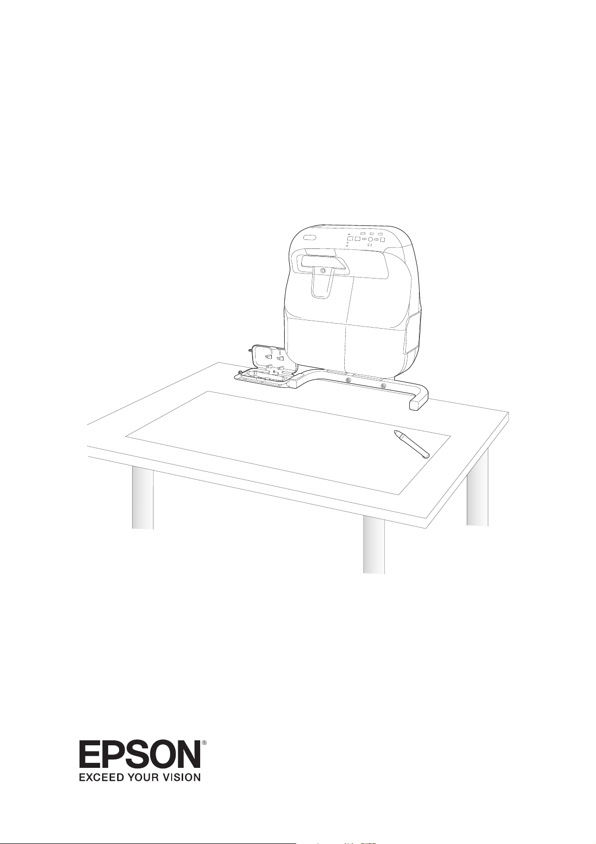
Epson BrightLink 475Wi, BrightLink 480i, BrightLink 485Wi, Ultra-Short Throw Table Mount User's Guide
Page 1
ELPMB29
Interactive Table Mount
Support de montage pour table interactive
Soporte para montaje en mesa interactiva
Suporte para mesa interativa
User’s Guide
Guide de l’utilisateur
Manual del usuario
Manual do usuário
Page 2

Page 3
Safety Instructions
g
For your safety, read all the instructions in this guide and your projector’s User's Guide before using this
product. Incorrect handling that ignores instructions in these guides could damage the product or could
result in personal injury or property damage. Keep this guide at hand for future reference.
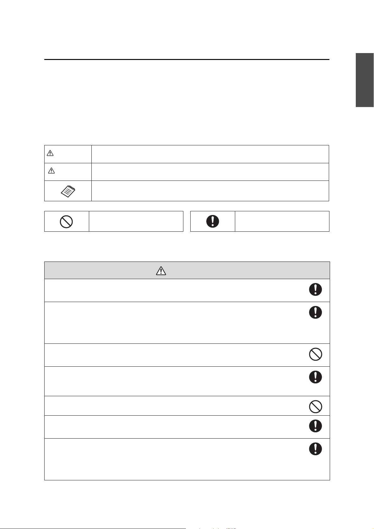
Explanation of Symbols
The symbols shown below are used throughout this guide to prevent personal injury or property damage.
Make sure you understand these warnings when reading this guide.
Warning
Caution
This symbol indicates information that, if ignored, could possibly result in personal injury or even death
due to incorrect handling.
This symbol indicates information that, if ignored, could possibly result in personal injury or physical
damage due to incorrect handling.
This symbol indicates relevant or useful information.
This symbol indicates an action that
must not be done.
This symbol indicates an action that
should be done.
Safety Precautions for Installation
English
Warnin
Follow the instructions in this guide when installing the product.
If the instructions are not followed, the mount may fall or collapse, resulting in personal injury or an accident.
Handle the power cord carefully.
Incorrect handling may cause fire or electric shock. Observe the following precautions when handling:
- Do not handle the power plug with wet hands.
- Do not use a power cord that is damaged or modified.
- Do not pull the power cord with too much force when passing it through the base frame unit.
Do not install this product in a place where it might be subjected to vibrations or shock.
Vibrations or shock could cause damage to the projector or mounting surface. It could also cause this mount or projector
to fall and cause serious personal injury or even death.
Inspect this product on a regular basis to ensure there are no broken parts or loose screws.
If there are any broken parts, stop using the mount immediately. Otherwise, the mount may collapse and the projector
may fall, causing damage or personal injury.
Never modify this product.
Tighten all screws firmly after installation.
Otherwise, the mount may collapse and the projector may fall, causing damage or personal injury.
Install this product on a table that meets the following conditions.
- The tabletop is 0.6 to 3.1 inches (15 to 80 mm) thick.
- The tabletop is strong enough to support the weight of the mount.
- The table is stable enough not to collapse after installation of the mount (legs are not pointing inwards or collapsible, for
example).
- The table is strong enough to support the weight of the projector and the mount.
Do not use screw-locking adhesives, lubricants, or oil to install this product on a table.
If you use screw-locking adhesives, lubricants or oil on the projector’s attachment plate, the case may crack and cause the
projector to fall, resulting in personal injury or property damage.
Do not lean against or apply any force to the table mount or projector.
Otherwise, the table mount or projector may fall or collapse and cause an accident or personal injury.
3
Page 4
Caution
Do not install this product in a location where the operating temperature for the projector may be
exceeded.
Such an environment may damage the projector.
About This Guide
This guide describes how to install the following projectors on a table using the Interactive Table Mount
(ELPMB29):
BrightLink® 475Wi/475Wi+/480i/485Wi/485Wi+
BrightLink 575Wi/575Wi+/585Wi/585Wi+/595Wi/595Wi+
BrightLink Pro 1410Wi
Note:
BrightLink model availability varies by country.
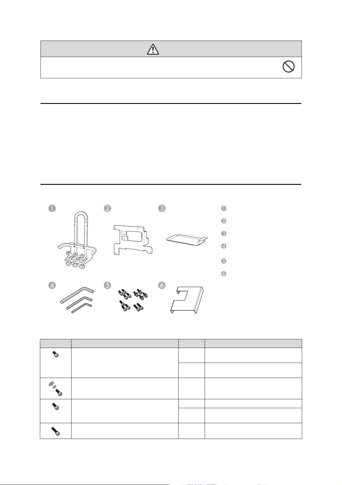
Package Contents
Base frame unit with adjuster bolts
Attachment plate
Accessory tray
Hexagon wrenches (for M3, M4,
and M8)
Bolts
Touch Unit attachment plate for
finger touch models
Bolts
Shape Name Quantity Application
M3 × 8 mm hexagon socket head cap bolt for
finger touch models
M4 × 12 mm hexagon socket head cap bolt with
washer and spring washer
2 For mounting the Touch Unit attachment
plate on the Touch Unit.
2 For mounting the Touch Unit attachment
plate to the base frame unit.
4 For mounting the attachment plate to the
projector.
M4 × 8 mm hexagon socket head cap bolt 1 For mounting the tray to the base frame unit.
M8 × 35 mm hexagon socket head cap bolt 2 For mounting the attachment plate to the
Have the necessary tools ready before you begin the installation.
4
2 Used as stoppers. (Pre-installed in the base
frame unit in mount position 2.)
base frame unit.
Page 5
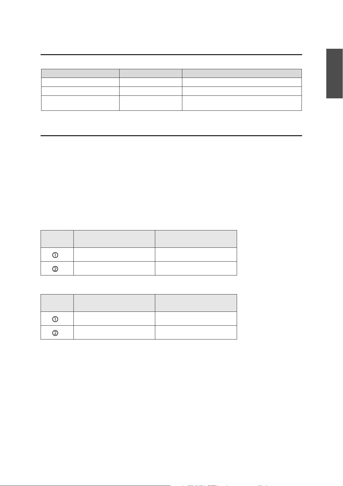
Specifications
Item Specification Note
Weight Approx. 16.75 lb (7.6 kg)
Maximum load capacity 14.3 lb (6.5 kg )
Forward/backward adjustment
range of the adjuster bolt
3.1 inches (80 mm) Distance between the edge of the table and the center of
the bolt: 1.4 to 4.5 inches (35 to 115 mm)
Table Requirements
Install the mount on a table that meets the following conditions.
The tabletop is strong enough to support the weight of the mount.
The table is stable enough not to collapse after installation of the mount.
The table is strong enough to support the weight of the projector and the mount.
The table surface is a light color such as white.
The tabletop is 0.6 to 3.1 inches (15 to 80 mm) thick.
The tabletop is larger than the minimum sizes below.
See the projection distance table on page 7 for the image size.
English
Minimum table sizes for BrightLink 475Wi/475Wi+/485Wi/485Wi+/575Wi/
575Wi+/585Wi/585Wi+/595Wi/595Wi+/BrightLink Pro 1410Wi
Mounting
position
65 inches (1651 mm) 47.6 × 55.8 inches (1210 × 1417 mm)
60 inches (1524 mm) 44.5 × 52 inches (1130 × 1321 mm)
Image size
(diagonal)
Rectangular table
Minimum table sizes for BrightLink 480i
Mounting
position
60 inches (1524 mm) 48.4 × 49.3 inches (1230 × 1252 mm)
56 inches (1422 mm) 45.7 × 46.1 inches (1160 ×1172 mm)
Image size
(diagonal)
Rectangular table
5
Page 6
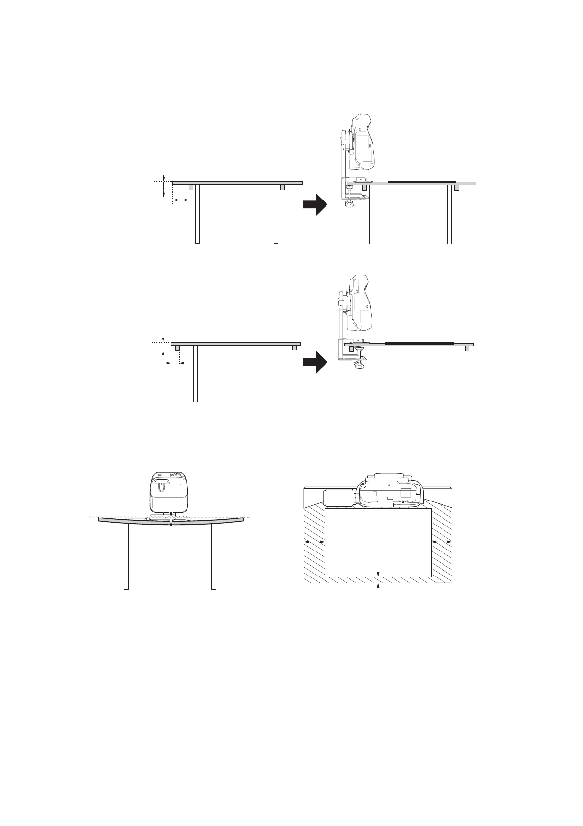
If any obstacles exist on the bottom side of the tabletop, the distance between the edge of the table and
the obstacle must be at least 3 inches (75 mm) or the obstacle must be within 3.3 inches (85 mm) from the
edge of the table.
0.6 to 3.1 inches
(15 to 80 mm)
3 inches or more
(75 mm or more)
0.6 to 3.1 inches
(15 to 80 mm)
0 to 3.3 inches
(0 to 85 mm)
For finger touch models, set up the Touch Unit on a flat, smooth, unwarped surface with no more than
0.2 inch (5 mm) of unevenness on the screen surface. Make sure there are no obstacles, such as cables, or
protruding items in the shaded areas in the following figure. The Touch Unit will not operate correctly if
anything is obstructing the infrared signal.
0.2 inch (5 mm)
4 inches
(100 mm)
0.8 inch (20 mm)
4 inches
(100 mm)
6
Page 7
Installation Procedure
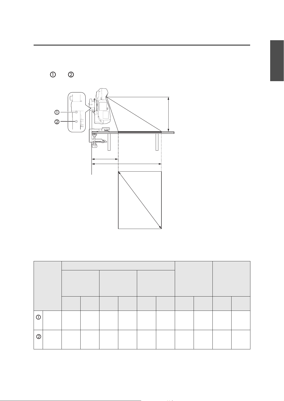
Determine the image size and the position of the projector
(1) Determine the position according to the image size. There are two positions to choose from:
and , as shown in the following illustration.
Y
a
b
English
S
Diagonal Image Sizes for Mounting Positions 1 and 2
BrightLink 475Wi/475Wi+/485Wi/485Wi+/575Wi/575Wi+/585Wi/585Wi+/595Wi/595Wi+/
BrightLink Pro 1410Wi
Mounting
position (Y)
15 in.
(380
mm)
13.8 in.
(350
mm)
Aspect ratio
16:10
Wide
(max)
65 in.
(1651
mm)
60 in.
(1524
mm)
Te le
(min)
48 in.
(1219
mm)
45 in.
(1143
mm)
Image size (S) Distance
Aspect ratio 4:3 Aspect ratio 16:9
between the
edge of the table
and the bottom
of the screen
(16:10) (a)
Wide
(max)
57 in.
(1448
mm)
53 in.
(1346
mm)
Te le
(min)
43 in.
(1092
mm)
40 in.
(1016
mm)
Wide
(max)
63 in.
(1600
mm)
59 in.
(1499
mm)
Te le
(min)
47 in.
(1194
mm)
45 in.
(1143
mm)
Wide
(max)
11.0 in.
(280
mm)
10.2 in.
(260
mm)
Te le
(min)
15.4 in.
(390
mm)
14.6 in.
(370
mm)
edge of the table
and the top of the
screen (16:10) (b)
(max)
45.3 in.
(1150
mm)
42.1 in.
(1070
mm)
Distance
between the
Wide
40.9 in.
(1040
mm)
38.6 in.
(980
mm)
Te le
(min)
7
Page 8
Diagonal Image Sizes for Mounting Positions 1 and 2
BrightLink 480i
Mounting
position (Y)
Aspect ratio
16:10
Image size (S) Distance
Aspect ratio 4:3 Aspect ratio 16:9
between the
edge of the table
and the bottom
of the screen
(16:10) (a)
Distance
between the
edge of the table
and the top of the
screen (16:10) (b)
15 in.
(380
mm)
13.8 in.
(350
mm)
Wide
(max)
57 in.
(1448
mm)
53 in.
(1346
mm)
Te le
(min)
42 in.
(1067
mm)
40 in.
(1016
mm)
Wide
(max)
60 in.
(1524
mm)
56 in.
(1422
mm)
Te le
(min)
45 in.
(1143
mm)
42 in.
(1067
mm)
Wide
(max)
55 in.
(1397
mm)
52 in.
(1321
mm)
Te le
(min)
41 in.
(1041
mm)
38 in.
(965
mm)
Wide
(max)
9.8 in.
(250
mm)
9.4 in.
(240
mm)
Te le
(min)
14.6 in.
(370
mm)
13.8 in.
(350
mm)
Wide
(max)
45.7 in.
(1160
mm)
42.9 in.
(1090
mm)
Te le
(min)
41.7 in.
(1060
mm)
39.0 in.
(990
mm)
You can change the image size using the projector’s Tele and Wide buttons.
You can adjust the projection position using the projector’s Image Shift feature.
(2) The mount ships with M4 × 8 mm hexagon socket head cap bolts (x2) secured in position
. To use mount position , remove the bolts from position before attempting to
mount the projector as shown on page 13.
M4 × 8 mm hexagon socket head
cap bolts
Mount positions
8
Page 9
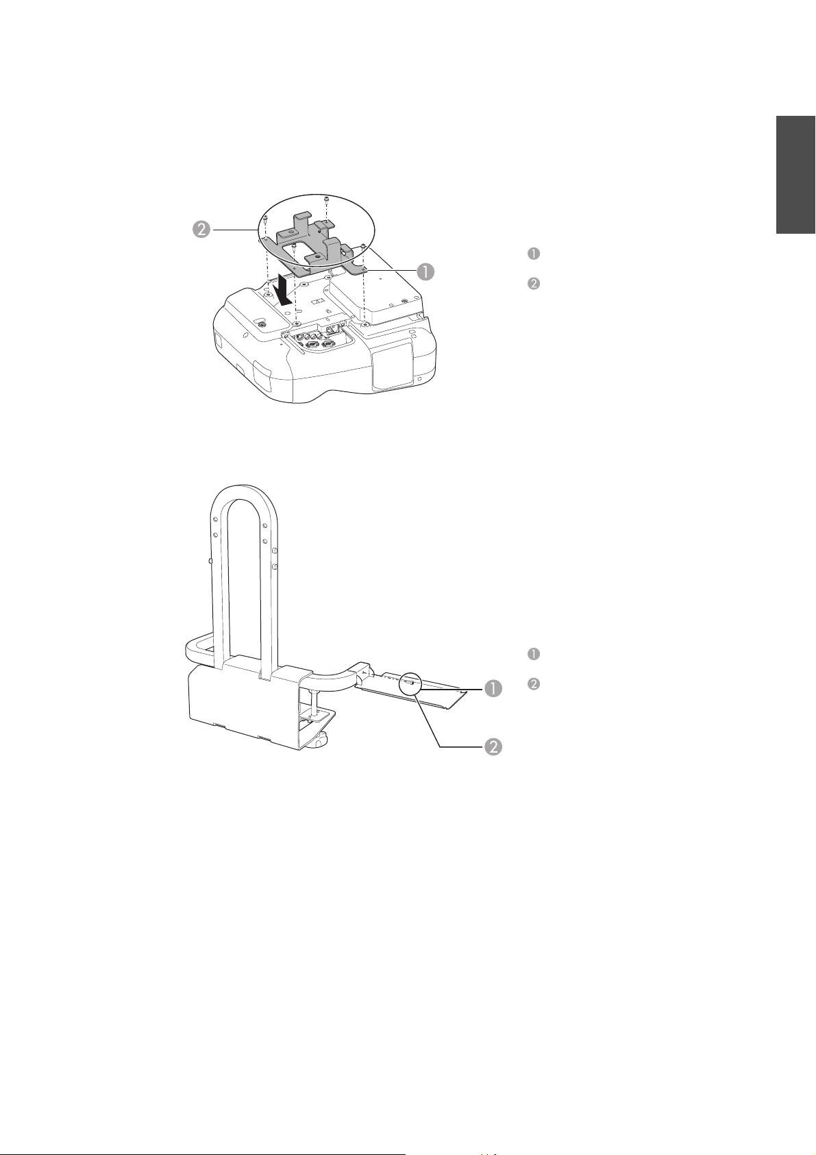
Assemble the parts
(1) Mount the attachment plate on the projector using M4 ×12 mm hexagon socket head cap
bolts (4 bolts with washer and spring washer).
Attachment plate
M4 × 12 mm hexagon socket head
cap bolts (with washer and spring
washer)
(2) Mount the tray on the base frame unit using an M4 × 8 mm hexagon socket head cap bolt.
You can mount the tray on either the left or right side of the base frame unit.
English
Accessory tray
M4 × 8 mm hexagon socket head
cap bolt
You can place the pen tray supplied with the projector on the accessory tray.
9
Page 10
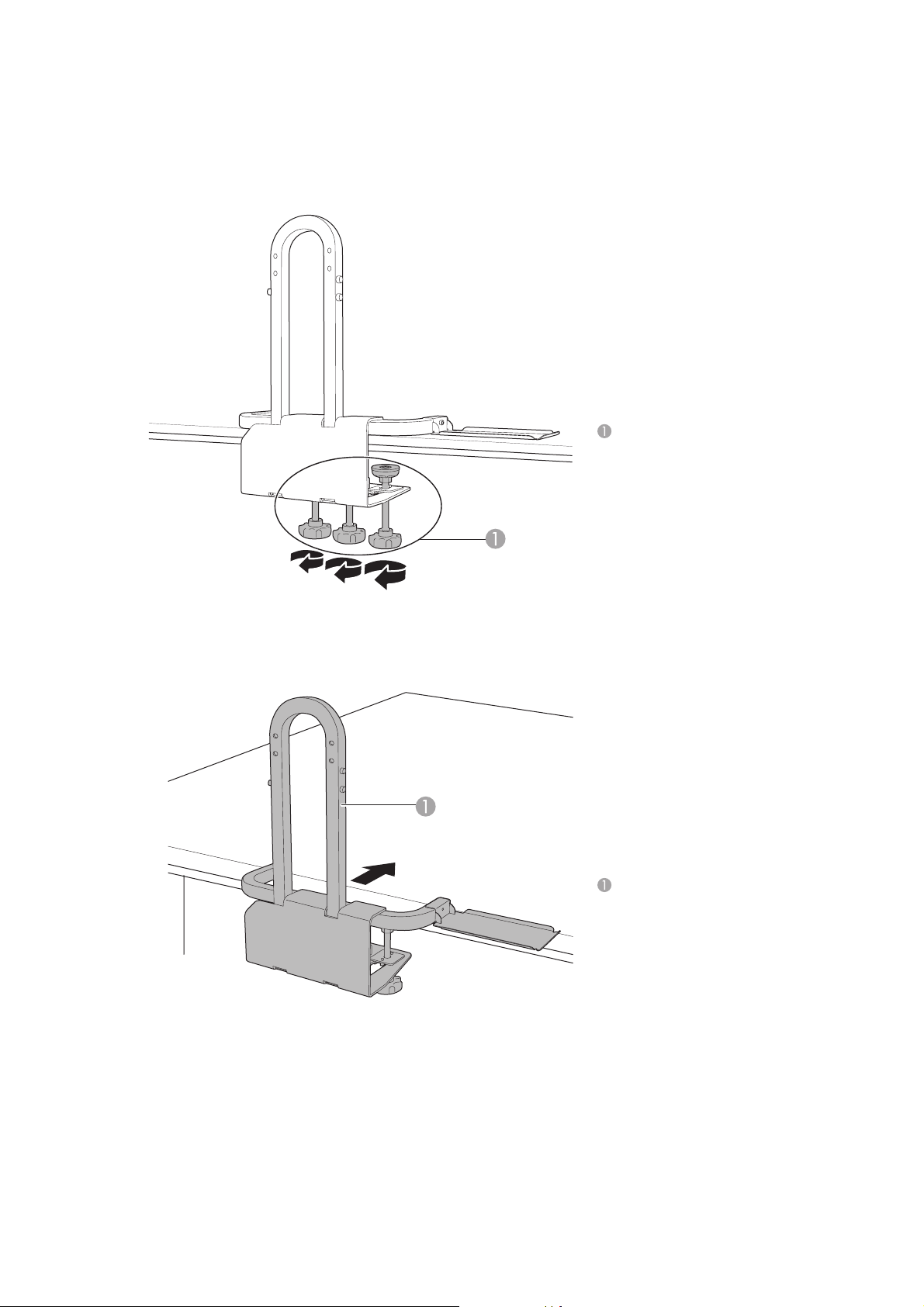
Temporarily mount the base frame unit
(1) Loosen the adjuster bolts (×3) to fit the thickness of the tabletop so you can attach the base
frame unit to the tabletop.
Adjuster bolts
(2) Attach the base frame unit to the table by sliding it onto the edge of the table.
Base frame unit
10
Page 11
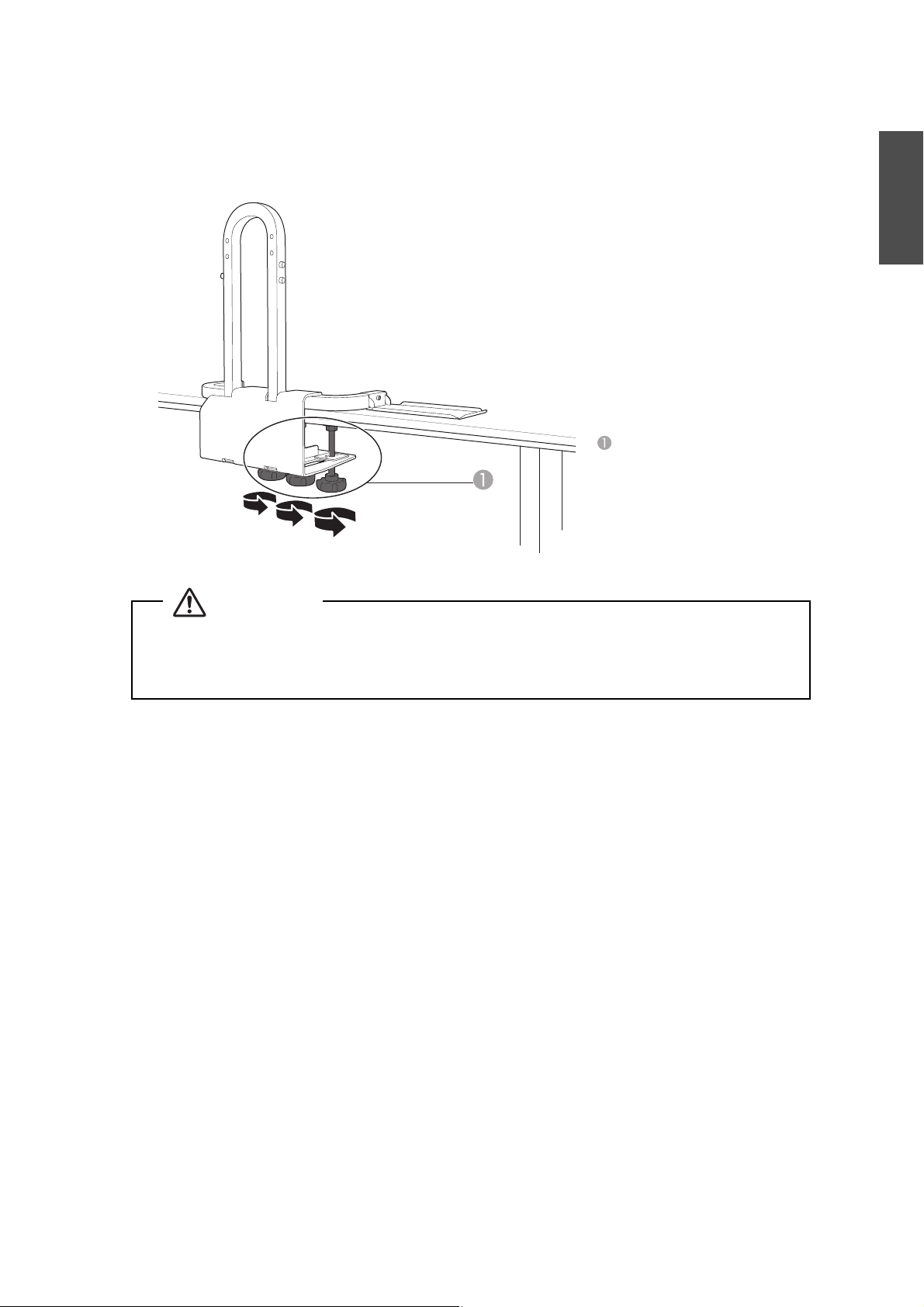
(3) Fix the adjuster bolts on a flat surface on the bottom side of the tabletop temporarily. Slide
the adjuster bolts forward or backward if there are any obstacles on the underside of the
table.
Adjuster bolts
Each adjuster bolt requires a flat
surface with at least 2.4 inches
(60 mm) in diameter.
English
Warning
❏ Tighten all adjuster bolts firmly after installation. Otherwise, the mount may collapse and
the projector may fall, causing damage or personal injury.
❏ Only tighten the adjuster bolts on the flat surface of the underside of the table.
11
Page 12
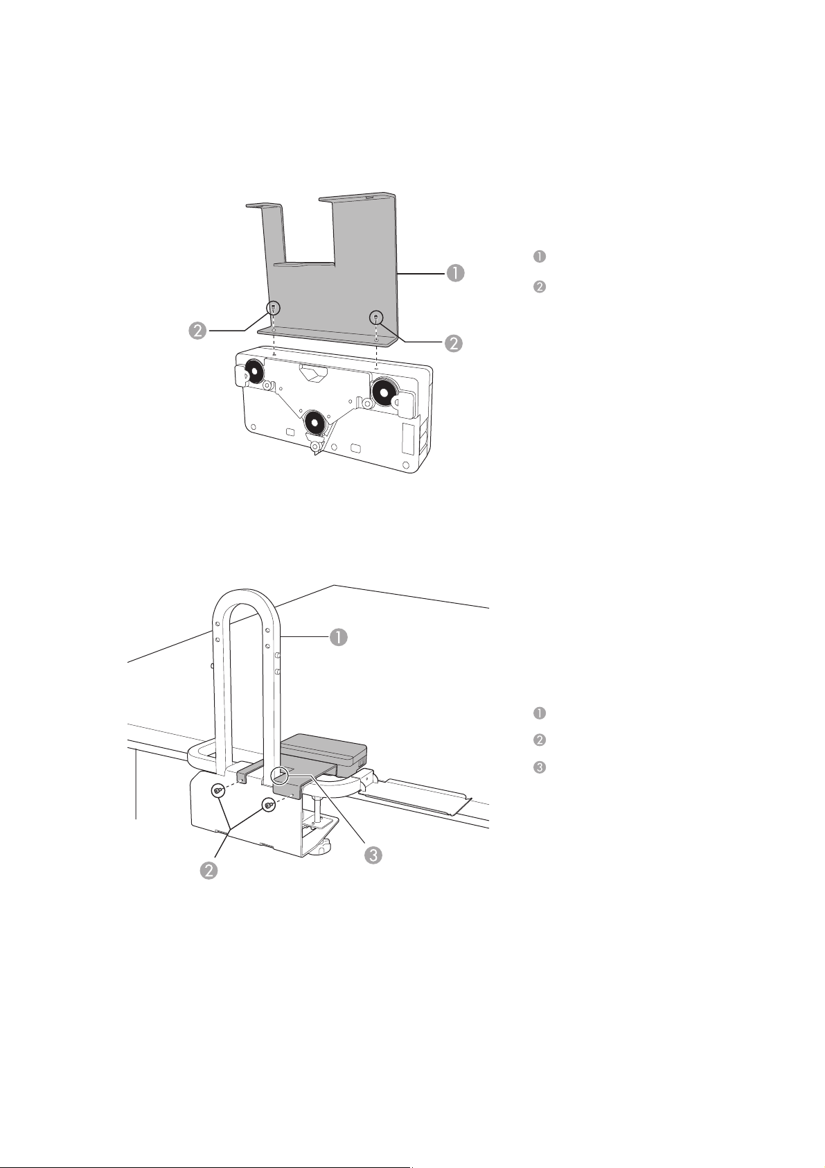
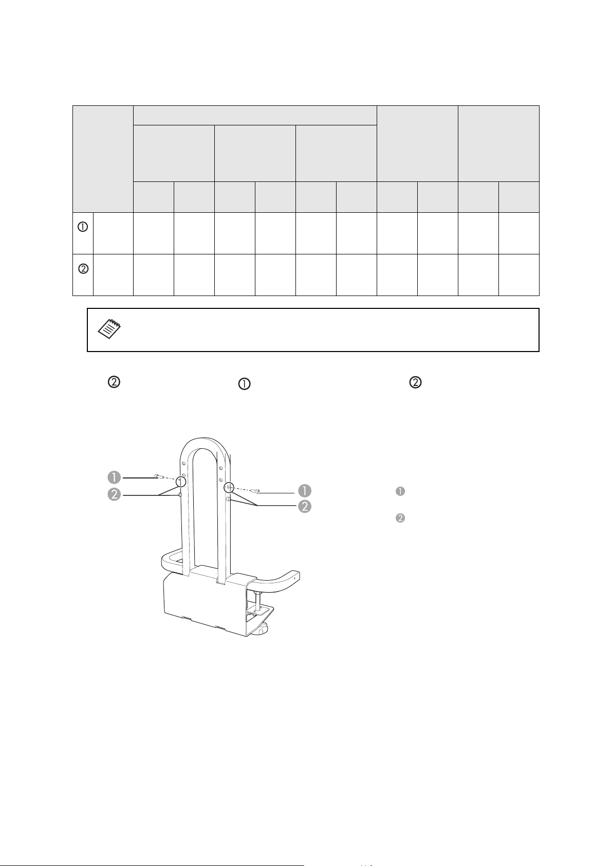
Install the Touch Unit attachment plate (finger touch models only)
(1) Mount the Touch Unit attachment plate on the Touch Unit using M3 × 8 mm hexagon socket
cap bolts (×2).
Touch Unit attachment plate
M3 × 8 mm socket cap bolt
(2) Mount the Touch Unit attachment plate on the base frame unit using M3 × 8 mm hexagon
socket cap bolts (×2).
Base frame unit
M3 × 8 mm socket cap bolt
Mount so that the Touch Unit
attachment plate is flush with the
side of the U-shaped arm.
12
Page 13
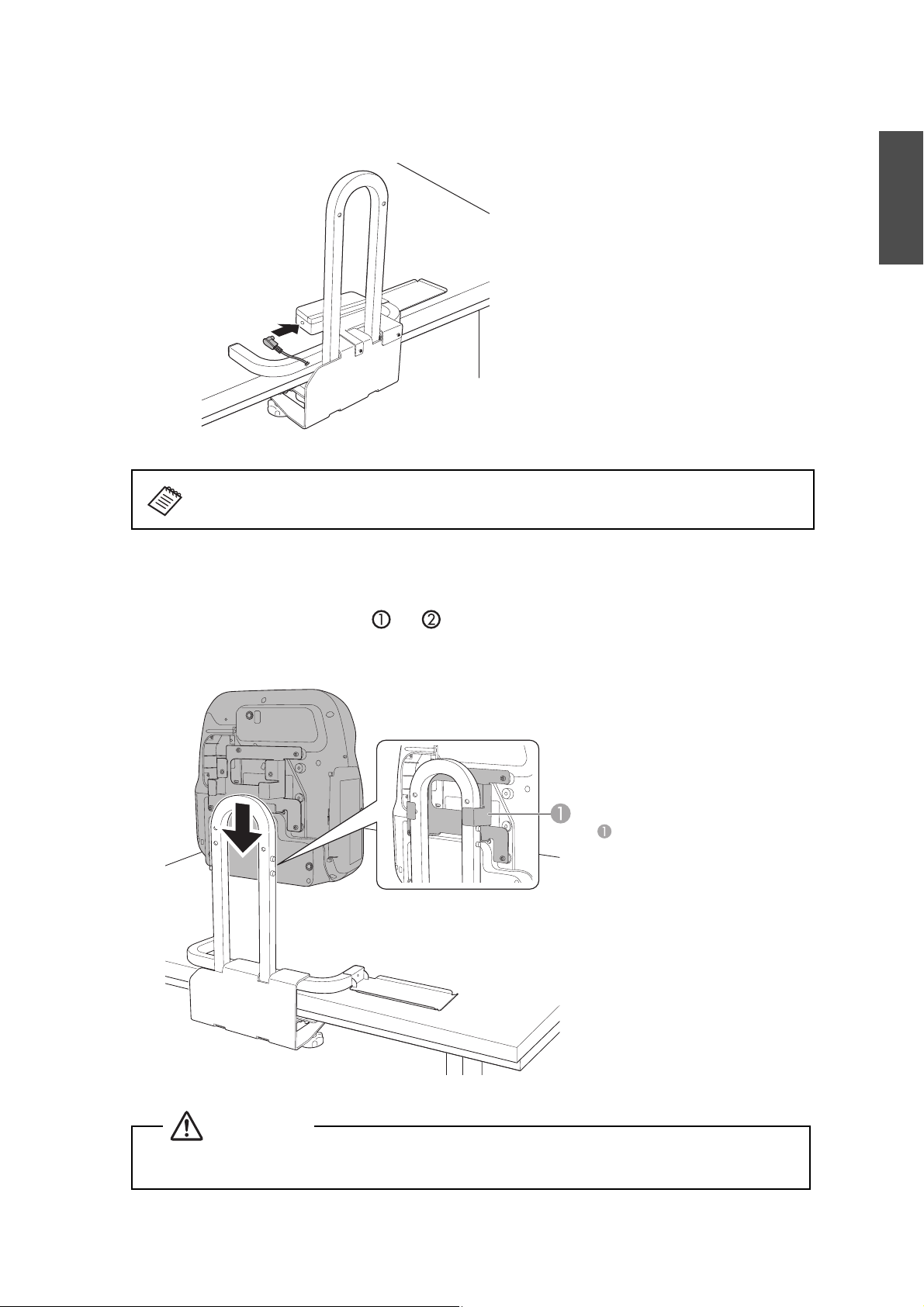
(3) Attach the connection cable that is supplied with the Touch Unit to the Touch Unit.
For more information on using the Touch Unit, see the projector’s Installation Guide and
User’s Guide.
Secure the projector to the base frame unit
English
(1) Slide the attachment plate mounted on the projector onto the U-shaped arch from the top.
It stops at mounting position or . For information on setting the mounting position,
see page 8.
Attachment plate
Caution
Do not place anything under the projector. It may damage the projector during the mounting
process.
13
Page 14
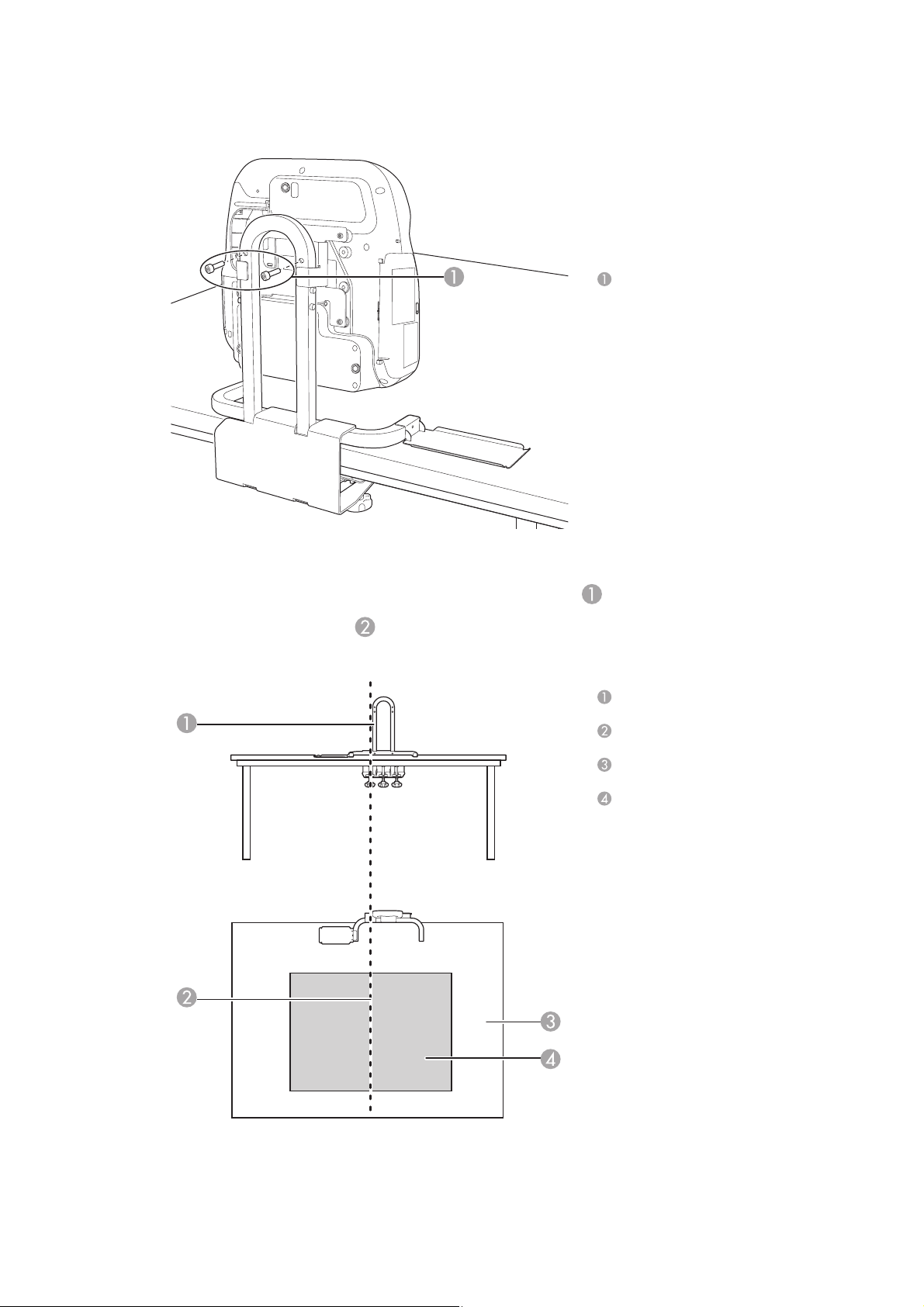
(2) Secure the projector with M8 × 35 mm hexagon socket head cap bolts (×2).
M8 × 35 mm hexagon socket head
cap bolts
Determine the position for attaching the table mount
(1) Align one side of the U-shaped arch on the base frame unit with the estimated center
line of the projected image to align the center of the lens and the center of the image.
U-shaped arch
Center of the image
Tab le
Projected image
14
Page 15
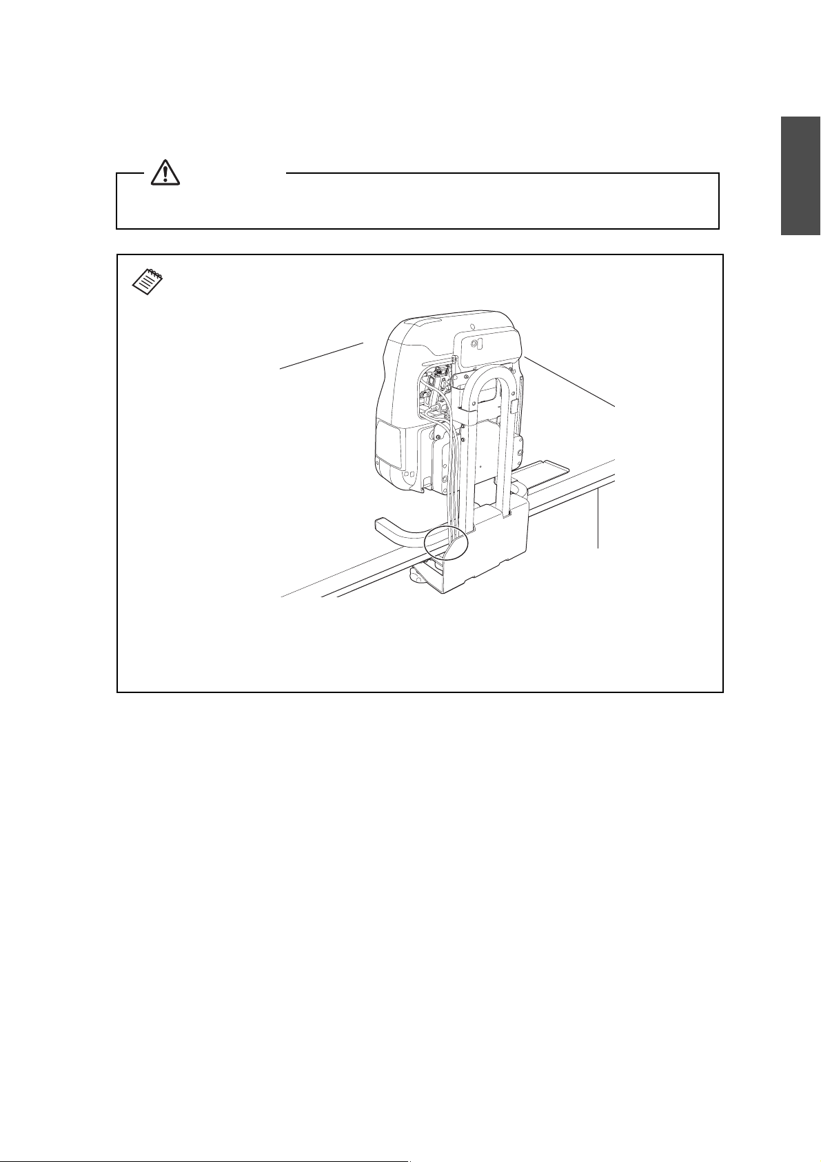
(2) Tighten the adjuster bolts that were temporarily fixed as shown on page 10. Make sure you
tighten the adjuster bolts with equal force.
Warning
Tighten all screws firmly. Otherwise, the projector or the mount may fall and cause personal
injury or damage.
When you have completed the projector installation, connect the necessary cables. Use
the cutout on the base frame unit so that the cables do not stick out.
English
For adjusting the image and more details on the projector, refer to the online User's
Guide at epson.com/support/brightlinkdownloads (US) or epson.ca/support/
brightlinkdownloads (Canada).
Make sure the table does not wobble after you have installed the projector.
15
Page 16

16
Page 17
Consignes de sécurité
Pour votre sécurité, veuillez lire toutes les consignes contenues dans ce guide et le Guide de l’utilisateur de
votre projecteur avant d’utiliser ce produit. Une manipulation incorrecte ne respectant pas ces consignes
pourrait endommager le produit ou provoquer des blessures corporelles ou des dommages matériels.
Conservez ce guide à portée de main pour pouvoir vous y reporter ultérieurement.
Explication des symboles
Les symboles ci-dessous sont utilisés dans ce guide afin de vous éviter de vous blesser ou de provoquer des
dommages matériels. Assurez-vous de bien avoir compris la signification de ces avertissements lorsque vous
lisez ce guide.
Français
Avertissement
Mise en garde
Ce symbole signale des informations qui, si elles sont ignorées, peuvent provoquer des blessures, voire la
mort, en raison d’une manipulation incorrecte.
Ce symbole indique des informations qui, si elles sont ignorées, peuvent provoquer des blessures ou des
dommages physiques, en raison d’une manipulation incorrecte.
Ce symbole signale des informations pertinentes ou utiles.
Ce symbole indique une action à ne pas
faire.
Ce symbole indique une action à faire.
Consignes de sécurité pour l’installation
Avertissement
Suivez les instructions du présent guide pour installer le produit.
En cas de non-respect des instructions, le support peut tomber ou s’affaisser et provoquer des blessures corporelles ou un
accident.
Manipulez le cordon secteur avec précaution.
Une manipulation incorrecte peut provoquer un incendie ou une électrocution. Prenez les précautions suivantes en le
manipulant:
- Ne saisissez pas la fiche secteur avec des mains humides.
- N’utilisez pas un cordon secteur endommagé ou modifié.
- Ne tirez pas exagérément sur le cordon lorsque vous le faites passer à travers le châssis.
N’installez pas ce produit à un endroit où il peut être soumis à des vibrations ou des chocs.
Des vibrations ou des chocs pourraient endommager le projecteur ou la surface de montage. Des vibrations ou des chocs
pourraient également entraîner la chute du support ou du projecteur et provoquer des blessures sérieuses ou la mort.
Vérifiez régulièrement le produit pour vérifier qu’aucune de ses pièces n’est endommagée ou que des vis
ne sont pas desserrées.
Si des pièces sont endommagées, cessez immédiatement d’utiliser le support. Sinon, le support pourrait s’effondrer et le
projecteur pourrait tomber et cela pourrait entraîner des dommages ou blessures corporelles.
Ne modifiez jamais ce produit.
Serrez fermement toutes les vis après l’installation.
Sinon, le support pourrait s’effondrer et le projecteur pourrait tomber et cela pourrait entraîner des dommages ou
blessures corporelles.
Installez ce produit sur une table remplissant les conditions suivantes.
- L’épaisseur du plateau est comprise entre 0,6 et 3,1 po (15 et 80 mm).
- La solidité du plateau est suffisante pour supporter le poids du support.
- La table est suffisamment stable pour ne pas s’affaisser après l’installation du support (les pieds ne sont pas orientés vers
l’intérieur et ne peuvent pas être pliés, par exemple).
- La solidité de la table est suffisante pour supporter le poids du projecteur et du support.
17
Page 18

Avertissement
N’utilisez pas d’adhésifs de freinage, ni de lubrifiants ou d’huiles pour installer ce produit sur une table.
Si vous utilisez des adhésifs de freinage, des lubrifiants ou des huiles sur la plaque de fixation du projecteur, le boîtier
risque de se détériorer, au risque de provoquer la chute du projecteur et des blessures corporelles ou des dommages
matériels.
Ne vous appuyez pas contre ni ne forcez sur la base de la table ou le projecteur.
Sinon, la base de la table ou le projecteur peut tomber ou s’affaisser et provoquer un accident ou des blessures
corporelles.
Mise en garde
N’installez pas ce produit dans un endroit où la température de fonctionnement du projecteur pourrait
être dépassée.
Un tel environnement peut endommager le projecteur.
À propos de ce guide
Ce guide décrit comment installer les projecteurs suivants sur une table à l’aide du support de montage pour
table interactive (ELPMB29) :
BrightLink®
BrightLink 575Wi/575Wi+/585Wi/585Wi+/595Wi/595Wi+
BrightLink Pro 1410Wi
475Wi/475Wi+/480i/485Wi/485Wi+
Remarque : La disponibilité des modèles BrightLink varie selon le pays.
Contenu de l’emballage
Châssis avec boulons de réglage
Plaque de fixation
Plateau pour accessoires
Clés à six pans (pour M3, M4 et M8)
Boulons
Plaque de fixation de l’unité tactile
pour les modèles avec commande
tactile
18
Page 19

Boulons
Forme Nom Quantité Application
Boulon à tête cylindrique à six pans M3 × 8 mm pour
les modèles avec commande tactile
Boulon à tête cylindrique à six pans M4 × 12 mm avec
rondelle et rondelle élastique
Boulon à tête cylindrique à 6 pans M4 × 8 mm 1 Pour le montage du plateau au
Boulon à tête cylindrique à 6 pans M8 × 35 mm 2 Pour le montage de la plaque de
2 Pour le montage de la plaque de
fixation de l’unité tactile sur l’unité
tactile.
2 Pour le montage de la plaque de
fixation de l’unité tactile au châssis.
4 Pour le montage de la plaque de
fixation au projecteur.
châssis.
2 Utilisé en tant que butées. (Pré-installé
dans le châssis en position de
montage 2.)
fixation au châssis.
Préparez les outils nécessaires avant de commencer l’installation.
Spécifications
Français
Élément Spécification Remarque
Poids Environ 16,75 lb (7,6 kg)
Capacité de charge maximale 14,3 lb (6,5 kg)
Plage de réglage vers l’avant/l’arrière
du boulon de réglage
3,1 po (80 mm) Distance entre le bord de la table et le centre du boulon :
1,4 à 4,5 po (35 à 115 mm)
Exigences pour la table
Installez ce support sur une table répondant aux exigences suivantes.
La solidité du plateau est suffisante pour supporter le poids du support.
Le table est suffisamment stable pour ne pas s’affaisser après l’installation du support.
La solidité de la table est suffisante pour supporter le poids du projecteur et du support.
La surface de la table est de couleur claire, blanche par exemple.
L’épaisseur du plateau est comprise entre 0,6 et 3,1 po (15 et 80 mm).
Le plateau est plus large que les formats minimum ci-dessous.
Consultez la table de distance de projection à la page 21 pour la taille de l’image.
Tailles minimales pour table pour les projecteurs BrightLink 475Wi/475Wi+/485Wi/
485Wi+/575Wi/575Wi+/585Wi/585Wi+/595Wi/595Wi+/BrightLink Pro 1410Wi
Position de
montage
Taille d’image
(diagonale)
Table rectangulaire
65 po (1651 mm) 47,6 × 55,8 po (1210 × 1 417 mm)
60 po (1524 mm) 44,5 × 52 po (1130 × 1 321 mm)
19
Page 20

Tailles minimales pour table pour le projecteur BrightLink 480i
Position de
montage
60 po (1524 mm) 48,4 × 49,3 po (1230 × 1 252 mm)
56 po (1422 mm) 45,7 × 46,1 po (1160 × 1172 mm)
Taille d’image
(diagonale)
Table rectangulaire
En présence d’obstacles dans le bas du plateau, la distance entre le bord de la table et l’obstacle doit être de
3 pouces (75 mm) minimum ou l’obstacle doit se trouver à 3,3 po (85 mm) du bord de la table.
0,6 à 3,1 po
(15 à 80 mm)
3 po ou plus
(75 mm ou plus)
0,6 à 3,1 po
(15 à 80 mm)
0 à 3,3 po
(0 à 85 mm)
Pour les modèles avec commande tactile, installez l’unité tactile sur une surface est plate, lisse et régulière
avec moins de 0,2 po (5 mm) d’inégalité sur la surface de l’écran. Assurez-vous qu’il n’y a pas d’obstacles,
par exemple des câbles ou des objets protubérants dans les zones ombrées de l’illustration ci-dessous.
L’unité tactile ne fonctionnera pas correctement si le signal infrarouge est bloqué.
0,2 po (5 mm)
4 po
(100 mm)
0,8 po (20 mm)
4 po
(100 mm)
20
Page 21

Procédure d’installation
Déterminer la taille d’image et la position du projecteur
(1) Déterminez la position en fonction de la taille d’image. Il y a deux positions possibles pour
l’installation : et , comme illustré ci-dessous.
Y
a
b
Français
S
Tailles d’image diagonales pour les positions de montage 1 et 2
BrightLink 475Wi/475Wi+/485Wi/485Wi+/575Wi/575Wi+/585Wi/585Wi+/595Wi/
595Wi+/BrightLink Pro 1410Wi
Position
de
montage
(Y)
15 po
(380
mm)
13,8 po
(350
mm)
Rapport largeur/
hauteur 16:10
Large
(max.)
65 po
(1651
mm)
60 po
(1524
mm)
Té lé
(min.)
48 po
(1219
mm)
45 po
(1143
mm)
Taille d’image (S) Distance entre le
Rapport largeur/
hauteur 4:3
Large
(max.)
57 po
(1448
mm)
53 po
(1346
mm)
Té lé
(min)
43 po
(1092
mm)
40 po
(1016
mm)
Rapport largeur/
hauteur 16:9
Large
(max.)
63 po
(1600
mm)
59 po
(1499
mm)
Té lé
(min.)
47 po
(1194
mm)
45 po
(1143
mm)
bord de la table
et le bas de
l’écran (16:10) (a)
Large
(max.)
11,0 po
(280
mm)
10,2 po
(260
mm)
(min.)
15,4 po
(390
mm)
14,6 po
(370
mm)
Té lé
Distance entre le
bord de la table
et le haut de
l’écran (16:10) (b)
Large
(max.)
45,3 po
(1150
mm)
42,1 po
(1070
mm)
Té lé
(min.)
40,9 po
(1040
mm)
38,6 po
(980
mm)
21
Page 22

Tailles d’image diagonales pour les positions de montage 1 et 2
BrightLink 480i
Position de
montage
(Y)
Rapport largeur/
hauteur 16:10
Taille d’image (S) Distance entre le
bord de la table
Rapport largeur/
hauteur 4:3
Rapport largeur/
hauteur 16:9
et le bas de
l’écran (16:10) (a)
Distance entre le
bord de la table
et le haut de
l’écran (16:10)
(b)
15 po
(380
mm)
13,8 po
(350
mm)
Large
(max.)
57 po
(1448
mm)
53 po
(1346
mm)
Té lé
(min.)
42 po
(1067
mm)
40 po
(1016
mm)
Large
(max.)
60 po
(1524
mm)
56 po
(1422
mm)
Té lé
(min.)
45 po
(1143
mm)
42 po
(1067
mm)
Large
(max.)
55 po
(1397
mm)
52 po
(1321
mm)
Té lé
(min.)
41 po
(1041
mm)
38 po
(965
mm)
Large
(max.)
9,8 po
(250
mm)
9,4 po
(240
mm)
Té lé
(min.)
14,6 po
(370
mm)
13,8 po
(350
mm)
Large
(max.)
45,7 po
(1160
mm)
42,9 po
(1090
mm)
Té lé
(min.)
41,7 po
(1060
mm)
39,0 po
(990
mm)
Vous pouvez changer la taille d’image à l’aide des boutons Tele et Wide du projecteur.
Vous pouvez régler la position de projection à l’aide de la fonction Décalage image du
projecteur.
(2) Le support est livré avec les boulons à tête cylindrique à six pans M4 × 8 mm (x2) fixés en
place . Pour utiliser la position de montage , retirez les boulons de la position
avant d’essayer de monter le projecteur tel qu’illustré à la page 28.
Boulons à tête cylindrique à 6 pans
× 8 mm
M4
Positions de montage
22
Page 23

Assembler les pièces
(1) Installez la plaque de fixation au projecteur à l’aide des boulons à tête cylindrique à six pans
M4 × 12 mm (4 boulons avec rondelle et rondelle élastique).
Plaque de fixation
Boulons à tête cylindrique à six
pans M4 × 12 mm (avec rondelle
et rondelle élastique)
(2) Montez le plateau sur le châssis en utilisant les boulons à tête cylindrique à six pans M4 × 8 mm.
Vous pouvez monter le plateau sur le côté gauche ou droit du châssis.
Français
Plateau pour accessoires
Boulon à tête cylindrique à 6 pans
M4 × 8 mm
Vous pouvez placer le plateau pour crayon fourni avec le projecteur sur le plateau pour
accessoires.
23
Page 24

Monter temporairement le châssis
(1) Desserrez les boulons de réglage (×3) en fonction de l’épaisseur du plateau afin de pouvoir
fixer le châssis au plateau.
Boulons de réglage
(2) Fixez le châssis à la table en faisant coulisser le châssis sur le bord de la table.
Châssis
24
Page 25

(3) Fixez temporairement les boulons de réglage à une surface plate dans le bas du plateau.
Faites glisser les boulons de réglage vers l’avant ou l’arrière s’il y a des obstacles en-dessous
de la table.
Boulons de réglage
Chaque boulon de réglage requiert
une surface plane de 2,4 po
(60 mm) de diamètre minimum.
Français
Avertissement
❏ Serrez fermement tous les boulons de réglage après l’installation. Sinon, le support
pourrait s’effondrer et le projecteur pourrait tomber et cela pourrait entraîner des
dommages ou blessures corporelles.
❏ Serrez seulement les boulons de réglage sur la surface plane du dessous de la table.
25
Page 26

Installer la plaque de fixation de l’unité tactile (seulement pour les modèles avec commande tactile)
(1) Montez la plaque de fixation de l’unité tactile sur l’unité tactile en utilisant des boulons à tête
cylindrique à six pans M3 × 8 mm (×2).
Plaque de fixation de l’unité tactile
Boulons à tête cylindrique à six
pans M3 × 8 mm
(2) Montrez la plaque de fixation de l’unité tactile sur le châssis en utilisant des boulons à tête
cylindrique à six pans M3 × 8 mm (×2).
Châssis
Boulons à tête cylindrique à six
pans M3 × 8 mm
Montez la plaque de fixation de
l’unité tactile en veillant à ce
qu’elle soit bien alignée avec le
côté du bras en U.
26
Page 27

(3) Branchez le câble de connexion fourni avec l’unité tactile à l’unité tactile.
Pour obtenir plus d’informations concernant l’unité tactile, consultez le Guide d’installation
et le Guide de l’utilisateur du projecteur.
Français
27
Page 28

Fixer le projecteur au châssis
(1) Faites coulisser la plaque de fixation installée sur le projecteur sur l’arc en forme de U situé
dans la partie supérieure.
Elle s’arrête à la position de montage ou . Pour obtenir plus d’informations sur la
position de montage, consultez la page 22.
Plaque de fixation
Mise en garde
Ne placez rien sous le projecteur. Cela pourrait endommager le projecteur pendant le montage.
(2) Fixez le projecteur à l’aide des boulons à tête cylindrique à six pans M8 × 35 mm (x2).
Boulons à tête cylindrique à 6 pans
× 35 mm
M8
28
Page 29

Déterminer la position de fixation de la base de la table
(1) Alignez l’un des côtés de l’arc en forme de U sur le châssis avec la ligne centrale estimée
de l’image projetée pour aligner le centre de l’objectif et le centre de l’image.
Arc en forme de U
Centre de l’écran
Tab le
Image projetée
Français
(2) Serrez les boulons de réglage qui avaient été temporairement fixés tel qu’illustré à la page 24.
Assurez-vous de serrer les boulons de réglage avec la même force.
Avertissement
Serrez fermement toutes les vis. Sinon, le projecteur ou ce support peut tomber ou s’affaisser et
provoquer des blessures corporelles ou des dommages.
29
Page 30

Une fois l’installation du projecteur terminée, connectez les câbles nécessaires. Utilisez
la découpe du châssis afin que les câbles ne soient pas serrés les uns contre les autres.
Pour le réglage de l’image ou pour obtenir plus de détails sur le projecteur, veuillez vous
référer au Guide de l’utilisateur en ligne à l’adresse epson.com/support/
brightlinkdownloads (É.-U.) ou epson.ca/support/brightlinkdownloads (Canada).
Assurez-vous que la table ne bouge pas après l’installation du projecteur.
30
Page 31

Instrucciones de seguridad
Para su seguridad, lea las instrucciones de este manual y del Manual del usuario del proyector antes de utilizar
este producto. Un manejo incorrecto sin seguir las instrucciones de estos manuales podría dañar el producto
o causar daños personales o materiales. Guarde este manual para futuras consultas.
Explicación de los símbolos
Los símbolos que se muestran a continuación aparecen en este manual para evitar daños personales o
materiales. Asegúrese de que entiende estas advertencias al leer este documento.
Español
Advertencia
Precaución
Este símbolo hace referencia a información que, si se ignora, podría causar daños personales e incluso la
muerte debido a un manejo incorrecto.
Este símbolo hace referencia a información que, si se ignora, podría causar daños personales y materiales
debido a un manejo incorrecto.
Este símbolo indica información relevante o útil.
Este símbolo indica una acción que no
se debe realizar.
Este símbolo indica una acción que sí se
debe realizar.
Precauciones de seguridad para la instalación
Advertencia
Siga las instrucciones de este manual para instalar el producto.
Si no sigue las instrucciones, el soporte se puede caer y provocar daños personales o accidentes.
Maneje el cable de alimentación con cuidado.
Un uso indebido puede provocar un incendio o una descarga eléctrica. Al manejarlo, tome las siguientes precauciones:
- No manipule el enchufe con las manos mojadas.
- No utilice un cable de alimentación dañado o modificado.
- No tire demasiado fuerte del cable de alimentación cuando lo dirija a través del chasis.
No instale este producto en un lugar donde pueda sufrir vibraciones o golpes.
Las vibraciones o golpes podrían dañar el proyector o la superficie de montaje. También podrían hacer que el soporte o el
proyector se caigan, provocando daños personales graves o incluso la muerte.
Revise regularmente este producto para garantizar que no haya piezas rotas o tornillos flojos.
Si hay piezas rotas, deje de utilizar el soporte inmediatamente. Si no, el montaje se podría desplomar y el proyector se
podría caer y provocar daños o lesiones personales.
Nunca modifique este producto.
Apriete firmemente todos los tornillos tras la instalación.
Si no, el montaje se podría desplomar y el proyector se podría caer y provocar daños o lesiones personales.
Instale este producto en una mesa que cumpla con las siguientes condiciones:
- La superficie de la mesa mide entre 0,6 y 3,1 pulg. (15 y 80 mm) de grosor.
- La superficie de la mesa es lo suficientemente fuerte para resistir el peso del producto.
- La mesa es lo suficientemente estable como para no desplomarse una vez instalado el soporte (por ejemplo, las patas no
están inclinadas hacia dentro ni son plegables).
- La mesa es lo suficientemente fuerte para resistir el peso del proyector y del soporte.
No utilice adhesivos de fijación, lubricantes o aceites para instalar el producto en una mesa.
Si utiliza adhesivos de fijación, lubricantes o aceites en la placa de fijación del proyector, se podría romper el exterior y
hacer que el proyector se caiga, provocando daños personales o materiales.
No se apoye ni ejerza fuerza en el soporte para montaje en mesa o en el proyector.
De lo contrario, el soporte para montaje en mesa o el proyector se podrían caer y provocar accidentes o daños personales.
31
Page 32

Precaución
No instale este producto en un lugar donde se pueda exceder la temperatura de funcionamiento del
proyector.
El proyector podría dañarse en tal situación.
Acerca de este manual
En este manual se describe cómo instalar los siguientes proyectores en una mesa utilizando el soporte para
montaje en pared (ELPMB29).
BrightLink® 475Wi/475Wi+/480i/485Wi/485Wi+
BrightLink 575Wi/575Wi+/585Wi/585Wi+/595Wi/595Wi+
BrightLink Pro 1410Wi
Nota: La disponibilidad de modelos BrightLink varía según el país.
Contenido del paquete
Chasis con pernos de fijación
Placa de fijación
Bandeja para accesorios
Llaves hexagonales (M3, M4 y M8)
Pernos
Placa de fijación de la unidad táctil
para modelos táctiles
Pernos
Forma Nombre Cantidad Uso
Perno de cabeza hexagonal M3 × 8 mm para
modelos táctiles
Perno de cabeza hexagonal M4 × 12 mm con
arandela y arandela de presión
2 Para montar la placa de fijación de la
unidad táctil en la unidad táctil.
2 Para montar la placa de fijación de la
unidad táctil en el chasis.
4 Para montar la placa de fijación en el
proyector.
Perno de cabeza hexagonal M4 × 8 mm 1 Para montar la bandeja en el chasis.
2 Se utilizan como topes. (Pre-instalados en
el chasis en la posición 2 del soporte).
Perno de cabeza hexagonal M8 × 35 mm 2 Para montar la placa de fijación en el
chasis.
Antes de comenzar la instalación, asegúrese de tener a mano las herramientas necesarias.
32
Page 33

Especificaciones
Elemento Especificación Nota
Peso Aprox. 16,75 lb (7,6 kg)
Capacidad máxima de carga 14,3 lb (6,5 kg)
Margen de ajuste hacia adelante/
atrás del perno de fijación
3,1 pulg. (80 mm) Distancia entre el borde de la mesa y el centro del perno:
1,4 a 4,5 pulg. (35 a 115 mm)
Requisitos de la mesa
Instale el soporte en una mesa que cumpla con las siguientes condiciones:
La superficie de la mesa es lo suficientemente fuerte para resistir el peso del producto.
La mesa es lo suficientemente estable como para no desplomarse una vez instalado el soporte.
La mesa es lo suficientemente fuerte para resistir el peso del proyector y del soporte.
La superficie de la mesa es de un color claro, como blanco.
La superficie de la mesa mide entre 0,6 y 3,1 pulg. (15 y 80 mm) de grosor.
La superficie de la mesa es más grande que los siguientes tamaños mínimos necesarios.
Consulte la tabla de distancias de proyección en la página 35 para el tamaño de la imagen.
Español
Tamaños mínimos de una mesa para los proyectores BrightLink 475Wi/475Wi+/
485Wi/485Wi+/575Wi/575Wi+/585Wi/585Wi+/595Wi/595Wi+/BrightLink Pro 1410Wi
Posición de
montaje
65 pulg. (1651 mm) 47,6 × 55,8 pulg. (1210 × 1417 mm)
60 pulg. (1524 mm) 44,5 × 52 pulg. (1130 × 1321 mm)
Tamaño de la imagen
(diagonal)
Mesa rectangular
Tamaños mínimos de una mesa para el proyector BrightLink 480i
Posición de
montaje
Tam año de l a ima gen
(diagonal)
60 pulg. (1524 mm) 48,4 × 49,3 pulg. (1230 × 1252 mm)
56 pulg. (1422 mm) 45,7 × 46,1 pulg. (1160 ×1172 mm)
Mesa rectangular
33
Page 34

Si hay obstáculos en la parte inferior de la superficie de la mesa, la distancia entre el borde de la mesa y el
obstáculo debe ser de al menos 3 pulg. (75 mm) o el obstáculo debe estar a 3,3 pulg. (85 mm) del borde
de la mesa.
0,6 a 3,1 pulg.
(15 a 80 mm)
3 pulg. o más
(75 mm o más)
0,6 a 3,1 pulg.
(15 a 80 mm)
0 a 3,3 pulg.
(0 a 85 mm)
Para modelos táctiles, instale la unidad táctil en una superficie plana, lisa y no combada con menos de
0,2 pulg. (5 mm) de irregularidad en la superficie de la pantalla. Asegure que no haya obstáculos (como
por ejemplo, cables) u objetos salientes en las áreas sombreadas indicadas en la siguiente ilustración. La
unidad táctil no funcionará correctamente si algún objeto está obstruyendo la señal de infrarrojos.
0,2 pulg. (5 mm)
4 pulg.
(100 mm)
0,8 pulg. (20 mm)
4 pulg.
(100 mm)
34
Page 35

Procedimiento de instalación
Determine el tamaño de la imagen y la posición del proyector
(1) Determine la posición según el tamaño de la imagen. Puede escoger entre dos posiciones:
y , tal como se muestra en la siguiente ilustración.
Y
a
b
Español
S
Tamaños diagonales de la imagen para las posiciones de montaje 1 y 2
BrightLink 475Wi/475Wi+/485Wi/485Wi+/575Wi/575Wi+/585Wi/585Wi+/595Wi/595Wi+/
BrightLink Pro 1410Wi
Posición de
montaje (Y)
15 pulg.
(380 mm)
13,8 pulg.
(350 mm)
Relación de
aspecto 16:10
Wide
(máx)
65 pulg.
(1651 mm)
60 pulg.
(1524 mm)
Tamaño de la imagen (S) Distancia entre
Te le
(mín)
48 pulg.
(1219 mm)
45 pulg.
(1143 mm)
Relación de
aspecto 4:3
Wide
(máx)
57 pulg.
(1448 mm)
53 pulg.
(1346 mm)
Te le
(mín)
43 pulg.
(1092 mm)
40 pulg.
(1016 mm)
Relación de
aspecto 16:9
Wide
(máx)
63 pulg.
(1600 mm)
59 pulg.
(1499 mm)
Te le
(mín)
47 pulg.
(1194 mm)
45 pulg.
(1143 mm)
11,0 pulg.
(280 mm)
10,2 pulg.
(260 mm)
el borde de la
mesa y la parte
inferior de la
pantalla (16:10)
(a)
Wide
(máx)
Te le
(mín)
15,4 pulg.
(390 mm)
14,6 pulg.
(370 mm)
Distancia entre el
borde de la mesa
pantalla (16:10)
Wide
(máx)
45,3 pulg.
(1150 mm)
42,1 pulg.
(1070 mm)
y la parte
superior de la
(b)
Te le
(mín)
40,9 pulg.
(1040 mm)
38,6 pulg.
(980 mm)
35
Page 36

Tamaños diagonales de la imagen para las posiciones de montaje 1 y 2
BrightLink 480i
Posición de
montaje (Y)
15 pulg.
(380 mm)
13,8 pulg.
(350 mm)
Relación de
aspecto 16:10
Wide
(máx)
57 pulg.
(1448 mm)
53 pulg.
(1346 mm)
Tamaño de la imagen (S) Distancia entre
Relación de
aspecto 4:3
Relación de
aspecto 16:9
pantalla (16:10)
Te le
(mín)
42 pulg.
(1067 mm)
40 pulg.
(1016 mm)
Wide
(máx)
60 pulg.
(1524 mm)
56 pulg.
(1422 mm)
Te le
(mín)
45 pulg.
(1143 mm)
42 pulg.
(1067 mm)
Wide
(máx)
55 pulg.
(1397 mm)
52 pulg.
(1321 mm)
Te le
(mín)
41 pulg.
(1041 mm)
38 pulg.
(965 mm)
9,8 pulg.
(250 mm)
9,4 pulg.
(240 mm)
el borde de la
mesa y la parte
inferior de la
(a)
Wide
(máx)
Te le
(mín)
14,6 pulg.
(370 mm)
13,8 pulg.
(350 mm)
Distancia entre el
borde de la mesa
y la parte
superior de la
pantalla (16:10)
(b)
Wide
(máx)
45,7 pulg.
(1160 mm)
42,9 pulg.
(1090 mm)
Puede cambiar el tamaño de la imagen utilizando los botones Tele y Wide del
proyector.
Puede ajustar la posición de proyección utilizando la función Cambio de imagen del
proyector.
(2) Al momento de envío del soporte, los pernos de cabeza hexagonal M4 × 8 mm (×2) están
fijados en la posición . Para utilizar la posición de montaje , retire los pernos de la
posición antes de tratar de instalar el proyector, tal como se muestra en la página 41.
Te le
(mín)
41,7 pulg.
(1060 mm)
39,0 pulg.
(990 mm)
Pernos de cabeza hexagonal
M4 × 8 mm
Posiciones de montaje
36
Page 37

Ensamble las piezas
(1) Instale la placa de fijación en el proyector utilizando los pernos de cabeza hexagonal
M4 × 12 mm (4 pernos con arandela y arandela de presión).
Placa de fijación
Pernos de cabeza hexagonal
M4 × 12 mm (con arandela y
arandela de presión)
(2) Instale la bandeja en el chasis utilizando un perno de cabeza hexagonal M4 × 8 mm.
Puede instalar la bandeja a la izquierda o a la derecha del chasis.
Español
Bandeja para accesorios
Perno de cabeza hexagonal
M4 × 8 mm
Puede colocar la bandeja para lápices proporcionada con el proyector en la bandeja para
accesorios.
37
Page 38

Instale el chasis temporalmente
(1) Afloje los pernos de fijación (×3) hasta que se ajusten al grosor de la superficie de la mesa, de
manera que pueda fijar el chasis a la superficie de la mesa.
Pernos de fijación
(2) Coloque el chasis en la mesa deslizándolo sobre el borde de la mesa.
Chasis
38
Page 39

(3) Fije temporalmente los pernos de fijación en una superficie plana en la parte inferior de la
superficie de la mesa. Si hay obstáculos en la parte inferior de la mesa, deslice los pernos de
fijación hacia delante o atrás.
Pernos de fijación
Cada perno de fijación necesita
una superficie plana de al menos
2,4 pulg. (60 mm) de diámetro.
Español
Advertencia
❏ Apriete firmemente todos los pernos de fijación tras la instalación. Si no, el montaje se
podría desplomar y el proyector se podría caer y provocar daños o lesiones personales.
❏ Sólo apriete los pernos de fijación en la superficie plana de la parte inferior de la mesa.
Instale la placa de fijación de la unidad táctil (modelos táctiles solamente)
(1) Instale la placa de fijación de la unidad táctil en la unidad táctil utilizando los pernos de
cabeza hexagonal M3 × 8 mm (×2).
Placa de fijación de la unidad táctil
Perno de cabeza hexagonal
M3 × 8 mm
39
Page 40

(2) Instale la placa de fijación de la unidad táctil en el chasis utilizando los pernos de cabeza
hexagonal M3 × 8 m (×2).
Chasis
Perno de cabeza hexagonal
M3 × 8 mm
Realice la instalación de modo que
la placa de fijación de la unidad
táctil esté contra el lado del brazo
en forma de U.
(3) Conecte el cable de conexión suministrado con la unidad táctil a la unidad táctil.
Para obtener más información sobre cómo utilizar la unidad táctil, consulte la Guía de
instalación y el Manual del usuario del proyector.
40
Page 41

Asegure el proyector al chasis
(1) Deslice desde arriba la placa de fijación montada en el proyector por el arco en forma de U.
Se parará en la posición de montaje o . Para obtener información sobre cómo
configurar la posición de montaje, consulte la página 36.
Placa de fijación
Español
Precaución
No coloque nada debajo del proyector. Podría dañar el proyector durante el proceso de
montaje.
(2) Fije el proyector con los pernos de cabeza hexagonal M8 × 35 mm (×2).
Pernos de cabeza hexagonal
M8 × 35 mm
41
Page 42

Determine la posición de instalación del soporte para montaje en mesa
(1) Para alinear el centro de la lente y el centro de la imagen, alinee un lateral del arco en forma
de U del chasis con la línea central estimada de la imagen proyectada .
Arco en forma de U
Centro de la imagen
Mesa
Imagen proyectada
(2) Apriete los pernos de fijación que estaban fijados temporalmente, tal como se muestra en la
página 38. Apriete todos los pernos de fijación con la misma fuerza.
Advertencia
Apriete firmemente todos los tornillos. Si no, el proyector o el soporte se podrían caer y
provocar daños o lesiones personales.
Cuando haya terminado la instalación del proyector, conecte los cables necesarios.
Utilice el hueco del chasis para que los cables no sobresalgan.
Para ajustar la imagen y otros detalles del proyector, consulte el Manual del usuario
del proyector.
Asegúrese de que la mesa no se tambalee una vez instalado el proyector.
42
Page 43

Instruções de segurança
Para sua segurança, leia todas as instruções neste manual e no Manual do usuário do seu projetor antes de
utilizar este produto. Um manuseamento incorreto que ignore as instruções contidas nestes manuais poderá
danificar o produto ou resultar em lesões pessoais ou danos materiais. Mantenha este manual disponível para
referência futura.
Explicação dos símbolos
Os símbolos apresentados a seguir são utilizados ao longo deste manual para evitar lesões pessoais ou danos
materiais. Assegure-se de que compreende estes símbolos quando ler este manual.
Português
Alerta
Cuidado
Este símbolo indica informação que, se ignorada, poderá resultar em lesões pessoais ou mesmo morte
devido ao manuseamento incorreto.
Este símbolo indica informação que, se ignorada, poderá resultar em lesões pessoais ou danos físicos
devido ao manuseamento incorreto.
Este símbolo indica informações pertinentes ou úteis.
Este símbolo indica uma ação que não
deve ser efetuada.
Este símbolo indica uma ação que deve
ser efetuada.
Precauções de segurança para instalação
Alerta
Siga as instruções neste manual quando instalar o produto.
Se não seguir as instruções, o produto poderá cair ou ceder, resultando em lesões pessoais ou acidente.
Manuseie o cabo de eletricidade com cuidado.
Um manuseamento incorreto poderá causar incêndio ou choque elétrico. Observe as precauções apresentadas a seguir
durante o manuseamento:
- Não manuseie o plugue com as mãos molhadas.
- Não utilize um cabo de eletricidade danificado ou alterado.
- Não puxe o cabo de eletricidade com muita força quando for passá-lo pela estrutura de base.
Não instale este produto em um local onde possa ficar sujeito a vibrações ou choques.
Vibrações ou choques poderão resultar em danos ao projetor ou superfície de montagem. Poderão, também, resultar na
queda deste produto ou do projetor e causar lesões pessoais graves ou mesmo morte.
Cheque este produto regularmente para se assegurar de que não existem peças partidas ou parafusos
soltos.
Se existirem peças partidas, pare de usar este produto imediatamente. Caso contrário, este produto ou o projetor poderá
cair ou ceder e causar danos ou lesões pessoais.
Nunca faça alterações a este produto.
Aperte firmemente todos os parafusos após a instalação.
Caso contrário, este produto ou o projetor poderá cair ou ceder e causar danos ou lesões pessoais.
Instale este produto em uma mesa que cumpra as condições indicadas a seguir.
- O tampo da mesa tem uma espessura de 15 a 80 mm (0,6 a 3,1 pol.).
- O tampo da mesa tem capacidade suficiente para suportar o peso deste produto.
- A mesa é suficientemente estável para não ceder após a instalação deste produto (por exemplo, as pernas não são
inclinadas para dentro ou articuladas).
- A mesa tem capacidade suficiente para suportar o peso do projetor e deste produto.
43
Page 44

Alerta
Não utilize adesivos para fixação de parafusos, lubrificantes ou óleos para instalar este produto em uma
mesa.
Se utilizar adesivos para fixação de parafusos, lubrificantes ou óleos na parte fixa da placa de fixação do projetor, o
gabinete poderá danificar-se e causar a queda do projetor, resultando em lesões pessoais ou danos materiais.
Não se incline nem aplique força no suporte de montagem para mesa ou no projetor.
Caso contrário, o suporte de montagem para mesa ou o projetor poderá cair ou ceder e causar acidente ou lesões
pessoais.
Cuidado
Não instale este produto em um local onde a temperatura de funcionamento para o projetor possa ser
excedida.
Esse tipo de ambiente poderá danificar o projetor.
Sobre este manual
Este manual descreve como instalar os projetores indicados a seguir em uma mesa utilizando o suporte
interativo para montagem em mesa (ELPMB29):
BrightLink® 475Wi/475Wi+/480i/485Wi/485Wi+
BrightLink 575Wi/575Wi+/585Wi/585Wi+/595Wi/595Wi+
BrightLink Pro 1410Wi
Observação: A disponibilidade dos modelos BrightLink varia dependendo do país.
Conteúdos da embalagem
Estrutura de base com parafusos
de ajuste
Placa de fixação
Bandeja de acessório
Chaves sextavadas (para M3, M4 e
M8)
Parafusos
Placa de fixação para a unidade de
toque
Parafusos
Formato Nome Quantidade Aplicação
Parafuso de cabeça cilíndrica sextavado
M3 × 8 mm para os modelos com unidade de
toque
2 Para montagem da placa de fixação da
unidade de toque na unidade de toque
2 Para montar a placa de fixação da unidade de
toque na estrutura de base.
44
Page 45

Parafusos
Parafuso de cabeça cilíndrica sextavado
M4 × 12 mm com arruela/arruela de pressão
4 Para montar a placa de fixação no projetor.
Português
Parafuso de cabeça cilíndrica sextavado
M4 × 8 mm
Parafuso de cabeça cilíndrica sextavado
M8 × 35 mm
1 Para montar a bandeja na estrutura de base.
2 Utilizados como fixadores. (Pré-instalado na
2 Para montar a placa de fixação na estrutura de
Prepare as ferramentas necessárias antes de iniciar a instalação.
Especificações
Item Especificação Observação
Peso Aprox. 16,75 lb (7,6 kg)
Capacidade de carga máxima 14,3 lb (6,5 kg)
Intervalo de ajuste para a frente/trás
do parafuso de ajuste
3,1 pol. (80 mm) Distância entre a extremidade da mesa e o centro do
parafuso: 1,4 a 4,5 pol. (35 a 115 mm)
Requisitos para a mesa
unidade da estrutura de base na posição de
montagem 2.)
base.
Instale este produto em uma mesa que cumpra as condições indicadas a seguir.
O tampo da mesa tem capacidade suficiente para suportar o peso deste produto.
A mesa é suficientemente estável para não ceder após a instalação deste produto.
A mesa tem capacidade suficiente para suportar o peso do projetor e deste produto.
A superfície da mesa é de cor clara como, por exemplo, branca.
O tampo da mesa tem uma espessura de 0,6 a 3,1 pol. (15 a 80 mm).
O tamanho do tampo da mesa é maior que os tamanhos mínimos a seguir.
Consulte a tabela de distância de projeção na página 47 para obter o tamanho da imagem.
Tamanhos de mesa mínimos para BrightLink 475Wi/475Wi+/485Wi/485Wi+/575Wi/
575Wi+/585Wi/585Wi+/595Wi/595Wi+/BrightLink Pro 1410Wi
Posição de
montagem
65 pol. (1651 mm) 47,6 × 55,8 pol. (1210 × 1417 mm)
60 pol. (1524 mm) 44,5 × 52 pol. (1130 × 1321 mm)
Tamanho da imagem
(diagonal)
Mesa retangular
Tamanhos de mesa mínimos para BrightLink 480i
Posição de
montagem
60 pol. (1524 mm) 48,4 × 49,3 pol. (1230 × 1252 mm)
Tamanho da imagem
(diagonal)
Mesa retangular
56 pol. (1422 mm) 45,7 × 46,1 pol. (1160 ×1172 mm)
45
Page 46

Se existir algum obstáculo na parte inferior do tampo da mesa, a distância entre a borda da mesa e o
obstáculo deve ser, pelo menos, de 3 pol. (75 mm) ou o obstáculo tem que estar afastado 3,3 pol. (85 mm)
da borda da mesa.
0,6 a 3,1 pol.
(15 a 80 mm)
3 pol. ou mais
(75 mm ou mais)
0,6 a 3,1 pol.
(15 a 80 mm)
0 a 3,3 pol.
(0 a 85 mm)
Para os modelos com unidade de toque, coloque a unidade de toque numa superfície plana, suave, sem
deformações na tela com não mais de 5 mm (0,2 pol.) de deformações. Certifique-se também de que não
existem obstáculos como, por exemplo, cabos ou objetos protuberantes, tais como, tabuleiros, suportes
ou molduras espessas do quadro branco nas áreas sombreadas na figura mostrada a seguir. A unidade de
toque não funcionará corretamente caso o sinal infravermelho encontre algum obstáculo.
0,2 pol (5 mm)
4 pol.
(100 mm)
0,8 pol (20 mm)
4 pol
(100 mm)
46
Page 47

Procedimento de instalação
Determine o tamanho da imagem e a posição do projetor
(1) Determine a posição de acordo com o tamanho da imagem. Pode escolher entre duas
posições: e , conforme mostrado na ilustração a seguir.
Y
a
b
Português
S
Tamanhos diagonais de imagem para posições de montagem 1 e 2
BrightLink 475Wi/475Wi+/485Wi/485Wi+/575Wi/575Wi+/585Wi/585Wi+/595Wi/595Wi+/
BrightLink Pro 1410Wi
Posição de
montagem
(Y)
15 pol.
(380 mm)
13,8 pol.
(350 mm)
Relação de
aspecto
de 16:10
Wide
(Máx.)
65 pol.
(1651
mm)
60 pol.
(1524
mm)
Tamanho de imagem (S) Distância entre a
borda da mesa e a
parte inferior da
tela (16:10) (a)
Wide
(Máx)
11,0 pol.
(280
mm)
10,2 pol.
(260
mm)
Te le
(Mín.)
48 pol.
(1219
mm)
45 pol.
(1143
mm)
Relação de
aspecto de 4:3
Wide
(Máx.)
57 pol.
(1448
mm)
53 pol.
(1346
mm)
(Mín.)
43 pol.
(1092
mm)
40 pol.
(1016
mm)
Te le
Relação de
aspecto de 16:9
Wide
(Máx.)
63 pol.
(1600
mm)
59 pol.
(1499
mm)
Te le
(Mín.)
47 pol.
(1194
mm)
45 pol.
(1143
mm)
Te le
(Mín)
15,4 pol.
(390
mm)
14,6 pol.
(370
mm)
Distância entre a
borda da mesa e a
parte superior da
Wide
(Máx)
45,3 pol.
(1150
mm)
42,1 pol.
(1070
mm)
tela (16:10) (b)
Te le
(Mín)
40,9 pol.
(1040
mm)
38,6 pol.
(980
mm)
47
Page 48

Tamanhos diagonais de imagem para posições de montagem 1 e 2
BrightLink 480i
Posição de
montagem
(Y)
Relação de
aspecto
de 16:10
Tamanho de imagem (S) Distância entre a
borda da mesa e a
Relação de
aspecto
de 4:3
Relação de
aspecto
de 16:9
parte inferior da
tela (16:10) (a)
Distância entre a
borda da mesa e a
parte superior da
tela (16:10) (b)
15 pol.
(380
mm)
13,8 pol.
(350
mm)
Wide
(Máx.)
57 pol.
(1448
mm)
53 pol.
(1346
mm)
Te le
(Mín.)
42 pol.
(1067
mm)
40 pol.
(1016
mm)
Wide
(Máx.)
60 pol.
(1524
mm)
56 pol.
(1422
mm)
Te le
(Mín.)
45 pol.
(1143
mm)
42 pol.
(1067
mm)
Wide
(Máx.)
55 pol.
(1397
mm)
52 pol.
(1321
mm)
Te le
(Mín.)
41 pol.
(1041
mm)
38 pol.
(965
mm)
Wide
(Máx)
9,8 pol.
(250
mm)
9,4 pol.
(240
mm)
Te le
(Mín)
14,6 pol.
(370
mm)
13,8 pol.
(350
mm)
Wide
(Máx)
45,7 pol.
(1160
mm)
42,9 pol.
(1090
mm)
É possível alterar o tamanho da imagem utilizando a função Tele e Wide do projetor.
É possível ajustar a posição da projeção utilizando a função Deslocar Imagem do
projetor.
(2) O suporte é fornecido com parafusos de cabeça cilíndrica sextavados M4 × 8 mm (2)
presos . Para usar a posição de montagem , remova os parafusos da posição antes
de tentar montar o projetor conforme mostrado na página 53.
Te le
(Mín)
41,7 pol.
(1060
mm)
39 pol.
(990
mm)
Parafusos de cabeça cilíndrica
sextavados M4 × 8 mm
Posições de montagem
48
Page 49

Monte as peças
(1) Monte a placa de fixação no projetor utilizando parafusos de cabeça cilíndrica sextavados
M4 × 12 mm (4 parafusos com arruela e arruela de pressão).
Placa de fixação
Parafusos de cabeça cilíndrica
sextavados M4 × 12 mm (com
arruela e arruela de pressão)
(2) Monte a bandeja na estrutura de base utilizando um parafuso de cabeça cilíndrica
sextavado M4 × 8 mm. Pode montar a bandeja no lado esquerdo ou no lado direito da
estrutura de base.
Português
Bandeja de acessório
Parafuso de cabeça cilíndrica
sextavado M4 × 8 mm
Pode colocar o suporte para caneta fornecido com o projetor na bandeja de acessório.
49
Page 50

Monte temporariamente a estrutura de base
(1) Solte os parafusos de ajuste (3) para corresponderem à espessura do tampo da mesa para
que possa prender a estrutura de base ao tampo da mesa.
Parafusos de ajuste
(2) Fixe a estrutura de base na mesa fazendo-a deslizar ao longo da borda da mesa.
Estrutura de base
50
Page 51

(3) Fixe temporariamente os parafusos de ajuste em uma superfície plana na parte inferior do
tampo da mesa. Deslize os parafusos de ajuste para a frente ou para trás, se houver
obstáculos na parte de baixo da mesa.
Parafusos de ajuste
Cada parafuso de ajuste requer
uma superfície plana com, pelo
menos, 60 mm (2,4 pol.) de
diâmetro.
Português
Alerta
❏ Aperte firmemente todos os parafusos de ajuste após a instalação. Caso contrário, este
produto ou o projetor poderá cair ou ceder e causar danos ou lesões pessoais.
❏ Só aperte os parafusos de ajuste na superfície plana na parte de baixo da mesa.
51
Page 52

Instale a placa de fixação da unidade de toque (apenas para modelos que incluem uma unidade de toque)
(1) Instale a placa de fixação da unidade de toque na unidade de toque utilizando os parafusos
de cabeça cilíndrica sextavados M3 × 8 mm (×2).
Placa de fixação da unidade de
toque
Parafusos de cabeça cilíndrica
sextavados M3 × 8 mm
(2) Instale a placa de fixação da unidade de toque na estrutura da base utilizando os parafusos
de cabeça cilíndrica sextavados M3 × 8 mm (×2).
Estrutura da base
Parafusos de cabeça cilíndrica
sextavados M3 × 8 mm
Instale de forma a que a placa de
fixação da unidade de toque fique
alinhada com a parte lateral do
braço em forma de U.
52
Page 53

(3) Conecte o cabo da unidade de toque fornecido com a unidade.
Para mais informações sobre a utilização da unidade de toque, consulte o Guia de instalação
e o Manual do usuário do projetor.
Fixe o projetor na estrutura de base
Português
(1) Faça deslizar a placa de fixação montada no projetor ao longo do arco em forma de U a partir
do topo. A placa irá parar na posição de montagem ou . Para informação sobre como
estabelecer a posição de montagem, veja a página 48.
Placa de fixação
Cuidado
Não coloque nada embaixo do projetor. Isso poderá danificar o projetor durante o processo de
montagem.
53
Page 54

(2) Fixe o projetor com os parafusos de cabeça cilíndrica sextavados M8 × 35 mm (2).
Parafusos de cabeça cilíndrica
sextavados M8 × 35 mm
Determine a posição para fixar o suporte para mesa
(1) Alinhe um lado do arco com formato de U na estrutura de base com a linha de centro
estimada da imagem projetada para alinhar o centro da lente e o centro da imagem.
Arco com formato de U
Centro da imagem
Mesa
Imagem projetada
54
Page 55

(2) Aperte os parafusos de ajuste que foram temporariamente fixados, conforme mostrado na
página 50. Assegure-se de apertar os parafusos de ajuste com força igual.
Alerta
Aperte firmemente todos os parafusos. Caso contrário, o projetor ou o suporte poderá cair e
causar lesões pessoais ou danos.
Depois de concluir a instalação do projetor, conecte os cabos necessários. Utilize o
recorte existente na estrutura de base para que os cabos não fiquem salientes.
Português
Para ajustar a imagem e para mais detalhes sobre o projetor, consulte o Manual do
usuário do projetor.
Depois de instalar o projetor, certifique-se de que a mesa se mantém firme.
55
Page 56

CPD-36439R1
Printed in XXXXXX
Pays d’impression : XXXXXX
Impresso en XXXXXX
País de impressão: XXXXXX
 Loading...