

Page 1
Page 2

EPSON
®
24-PIN DOT MATRIX PRINTER
ActionPrinter™ 5000+
User’s Guide
Page 3
NOTICE
NOTE
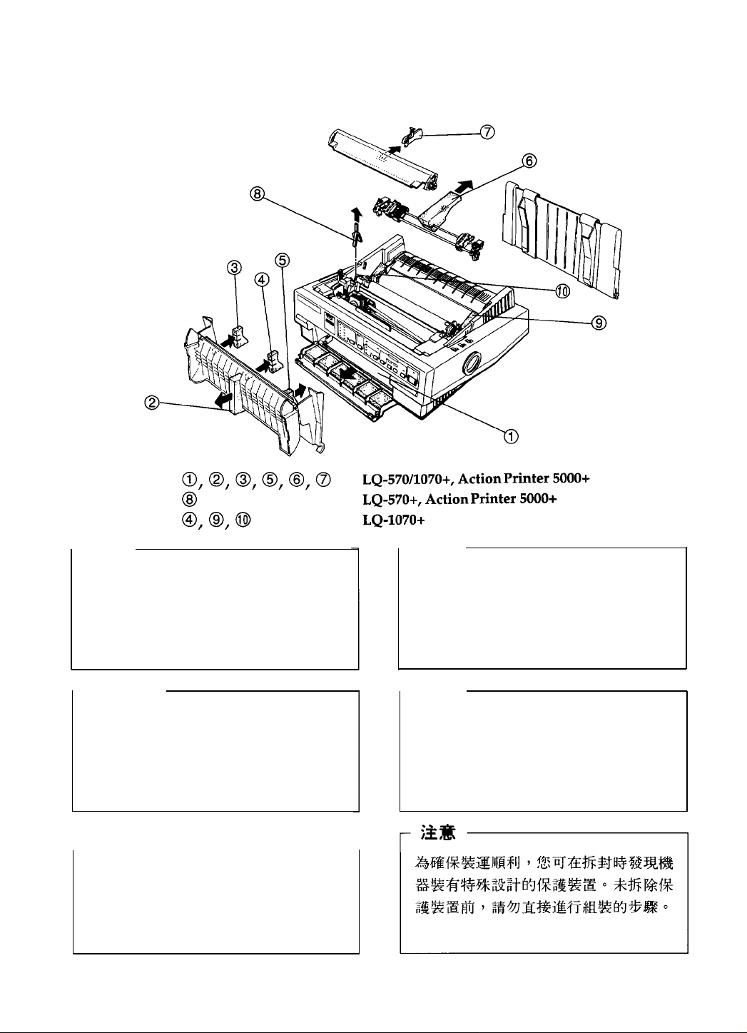
To prevent damage during shipping,
several pieces of protective material are
packed with your printer. You must
remove these before you assemble your
printer.
-HINWEIS
Zur Vermeidung von Transportschäden
wurde der Drucker durch schützende
Verpackungsteile gesichert. Diese Teile
mssen
vor dem Zusammenbau des
Druckers entfernt werden.
ATTENTION
Afin d’eviter tout dommage durant le
transport, des matériaux de protection
ont été emballés avec l’imprimante.
Veillez à bien les retirer avant de
I’installer.
Printed in U.S.A. 95.01 -12.5
- NOTA
L’imballaggio della vostra stampante
contiene molti elementi protettivi, per
prevenire danni durante il trasporto. Non
dimenticate di toglierli prima di iniziare a
utilizzare la stampante.
NOTA
Para evitar daños durante el transport, su
impresora viene protegida por varias
piezas de material protector. Debe retirar
estas piezas antes de montar su impresora.
400213800D0
R01 -00
Page 4

All rights reserved. No part of this publication may be reproduced, stored in a retrieval
system, or transmitted in any form or by any means, mechanical, photocopying,
record ing, or otherwise, without the prior written permission of Seiko Epson Corporation.
No patent liability is assumed with respect to the use of the information contained herein.
While every precaution has been taken in the preparation of this book, Seiko Epson
Corporation assumes no responsibility for errors or omissions. Neither is any liability
assumed for damages resulting from the use of the information contained herein.
Neither Seiko Epson Corporation nor its affiliates shall be liable to the purchaser of this
product or third parties for damages, losses, costs, or expenses incurred by purchaser or
third parties as a result of accident, misuse, or abuse of this product or unauthorized
modifications, repairs, or alterations to this product, or (excluding the U. S.) failure to
strictly comply with Seiko Epson Corporation’s operating and maintenance instructions.
Seiko Epson Corporation shall not be liable against any damages or problems arising from
the use of any options or any consumable products other than those designated as
Original Epson Products or Epson Approved Products by Seiko Epson Corporation.
Epson and Epson ESC/P are registered trademarks and Epson ESC /P 2 is a trademark of
Seiko Epson Corporation.
IBM and IBM PC are trademarks of International Business Machines Corporation
Helvetica and Times are trademarks of Linotype AG and/or its subsidiaries.
Copyright © 1992 by Seiko Epson Corporation
Nagano, Japan
ii
Page 5

FCC Compliance Statement
For United States Users
This equipment has been tested and found to comply with the limits for a Class B digital
device, pursuant to Part 15 of the FCC Rules. These limits are designed to provide
reasonable protection against harmful interference in a residential installation. This
equipment generates, uses and can radiate radio frequency energy and, if not installed
and used in accordance with the instructions, may cause harmful interference to radio or
television reception. However, there is no guarantee that interference will not occur in a
particular installation. If this equipment does cause interference to radio and television
reception, which can be determined by turning the equipment off and on, the user is
encouraged to try to correct the interference by one or more of the following measures.
Reorient or relocate the receiving antenna
Increase the separation between the equipment and receiver
Connect the equipment into an outlet on a circuit different from that to which the
receiver is connected
Consult the dealer or an experienced radio/TV technician for help.
WARNING
The connection of a non-shielded equipment interface cable to this equipment will
invalidate the FCC Certification of this device and may cause interference levels which
exceed the limits established by the FCC for this equipment. It is the responsibility of the
user to obtain and use a shielded equipment interface cable with this device. If this
equipment has more than one interface connector, do not leave cables connected to
unused interfaces.
Changes or modifications not expressly approved by the manufacturer could void the
users authority to operate the equipment.
For Canadian Users
This digital apparatus does not exceed the Class B limits for radio noise emissions from
digital apparatus as set out in the radio interference regulations of the Canadian
Department of Communications.
Le présent appareil numénque n’émet pas de bruits radioélectriques dépassant les limites
applicable aux appareils numériques de Classe B prescribes dans le règlement sur le
brouillage radioélectrique édicté par le Ministère des Communications du Canada.
iii
Page 6

TIPS FOR PRINTING ON SINGLE SHEETS
There are a few things you should know about printing on
single sheets as opposed to continuous paper. When you print
on single sheets, you may notice that your printer prints the
first page of your file correctly but then prints too low on the
next page, or that it prints the last few lines from one page onto
the next.
These differences in print position are easy to adjust; you can
simply change some of the settings in your software as
described below to get the right results.
1. When you install software, it normally asks you what printer
you are using. Make sure you choose the correct printer.
See Chapter 1 for the right printer to choose.
2 Many programs include an option to set the maximum lines
per page. If your program has a lines-per-page setting and
you are using standard 8½ x 11-inch paper, set the lines
per page to 61.
Note:
To find the right lines-per-page setting for paper that is not 8½ x
11, create a test document using your software. Set your top and
bottom margins to 0 and then create a file of numbered lines from
1 to 66. When you print your file, notice the last number printed
on the first page. This is your maximum lines-per-page setting.
3.
If your program doesn’t have a lines-per-page setting, try
decreasing the top margin or increasing the bottom
margin, or both, until you get the results you want.
4. You can also try adjusting the form length setting. For a
standard 8½ x 11l-inch page, try setting the form length at
10 inches.
5.
Some programs also let you indicate whether you are using
single sheets or continuous paper. Make sure you choose
single sheets.
iv
Page 7

Where to Get Help for United States
Users
Epson America provides customer support and service
through a nationwide network of authorized Epson dealers
and Service Centers.
Epson also provides the following support services through
the Epson Consumer Resource Center at (800) 922-8911:
Assistance in locating your nearest Authorized Epson
Reseller or Service Center
Technical assistance with the installation, configuration,
and operation of Epson products
Information on software drivers
Sales of the Epson ESC/P Reference Manual, which
contains comprehensive information on ESC/P 2
Epson technical information library fax service
Product literature with technical specifications on our
current and new products
Sales of ribbons, supplies, parts, documentation, and
accessories for your Epson product
Customer Relations
Information about user groups
v
Page 8

For United Kingdom Users
Epson product guarantee
Under the law, goods sold must comply with their description
and must be of merchantable quality and fit for their purpose
or correspond with any sample.
This guarantee does not affect the seller’s legal obligation or
the rights of the consumer in the “consumer transactions”
under any Statute, including Sections 12 to 15 of the Sales of
Goods Act, 1979.
All Epson Products, other than OEM products, are fully
guaranteed against faulty operation or performance for a
period of
product.
All claims under this guarantee MUST be supported by
evidence of purchase, normally the bill of sale invoice, and it is
the responsibility of the claimant to furnish such proof. Epson
(UK) Limited does not issue or operate any form of guarantee
registration card.
ONE YEAR
from date of purchase by the user of the
Claims are made by the user returning the product to the
supplier from whom it was purchased or, if this is impractical,
to any Epson supplier who also handles the same product. In
the event of any difficulty, users are requested to contact the
Service Co-ordinator Manager at Epson (UK) Limited.
Epson (UK) limited, or Epson Appointed Distributors, will at
their discretion repair or replace part or all of the product to
provide, in their judgement, a satisfactory performance of the
product consistent with its age and apparent usage.
This guarantee covers the cost of both the parts and labour
required to correct any malfunction of the equipment, but
specifically excludes wear and tear, consumables, physical
damage due to unauthorized and inexpert repair.
vi
Page 9

The guarantee is restricted to the performance of the product
alone, and Epson (UK) Limited does not accept responsibility
for any consequential loss or damage, nor claimed or implied
performance, when the product is used in any combination
with other equipment or program software.
Product guarantee may be invalidated as a result of excessive
or inappropriate use, use in adverse environment or in
conditions outside the specifications or if the product has been
subjected to unapproved modifications.
The guarantee does not cover visits to the user’s premises or
the repair or commissioning of the product on site.
Use of options
Epson (UK) Limited shall not be liable against any damages or
problems arising from the use of any options or consumable
products other than those designated as Original Epson
Products or Epson Approved Products by Epson (UK) Limited.
Safety information
Warning: This appliance must be earthed. Refer to rating
plate for voltage and check that the appliance voltage
corresponds to the supply voltage.
Important: The wires in the mains lead fitted to this appliance
are coloured in accordance with the following code:
Green and yellow - Earth
Blue - Neutral
Brown - Live
As the colours of the wires in the mains lead of this appliance
may not correspond with the coloured markings identifying
the terminals in your plug, proceed as follows:
vii
Page 10

The green and yellow wire must be connected to the terminal
in the plug which is marked with the letter E or with the earth
symbol or coloured green or green and yellow.
The blue wire must be connected to the terminal in the plug
marked with the letter N or coloured black.
The brown wire must be connected to the terminal in the plug
marked with the letter L or coloured red.
If damage occurs to the plug, replace the cord set or consult a
qualified electrician.
Replace fuses only with a fuse of the correct size and rating.
viii
Page 11

IMPORTANT SAFETY INSTRUCTIONS
1.
Read all of these instructions and save them for later
reference.
2.
Follow all warnings and instructions marked on the product.
3.
Unplug this product from the wall outlet before cleaning. Do
not use liquid cleaners or aerosol cleaners. Use a damp
cloth for cleaning.
4.
Do not use this product near water.
Do not place this product on an unstable cart, stand, or table.
5.
The product may fall, causing serious damage to the
product.
6.
Slots and openings in the cabinet and the back or bottom are
provided for ventilation; to ensure reliable operation of the
product and to protect it from overheating, these openings
must not be blocked or covered. The openings should
never be blocked by placing the product on a bed, sofa,
rug, or other similar surface. This product should never be
placed near or over a radiator or heat register. This product
should not be placed in a built-in installation unless proper
ventilation is provided.
7.
This product should be operated from the type of power
source indicated on the marking label. If you are not sure
of the type of power available, consult your dealer or local
power company.
8.
This product is equipped with a 3-wire grounding-type plug,
a plug having a third (grounding) pin. This plug will only
fit into a grounding-type power outlet. This is a safety
feature. If you are unable to insert the plug into the outlet,
contact your electrician to replace your obsolete outlet. Do
not defeat the purpose of the grounding-type plug.
ix
Page 12

9. Do not locate this product where the cord will be walked on.
10. If an extension cord is used with this product, make sure
that the total of the ampere ratings on the products
plugged into the extension cord does not exceed the
extension cord ampere rating. Also, make sure that the
total of all products plugged into the wall outlet does not
exceed 15 amperes.
11. Never push objects of any kind into this product through
cabinet slots as they may touch dangerous voltage points
or short out parts that could result in a risk of fire or
electric shock. Never spill liquid of any kind on the
product.
12. Except as specifically explained in the User’s Manual, do not
attempt to service this product yourself. Opening or
removing those covers that are marked “Do Not Remove”
may expose you to dangerous voltage points or other risks.
Refer all servicing in those compartments to service
personnel.
13. Unplug this product from the wall outlet and refer servicing
to qualified service personnel under the following
conditions:
A. When the power cord or plug is damaged or frayed
B. If liquid has been spilled into the product
C. If the product has been exposed to rain or water
D. If the product does not operate normally when the
operating instructions are followed. Adjust only those
controls that are covered by the operating instructions
since improper adjustment of other controls may result
in damage and will often require extensive work by a
qualified technician to restore the product to normal
operation.
x
Page 13

E. If the product has been dropped or the cabinet has been
damaged.
F. If the product exhibits a distinct change in performance,
indicating a need for service.
xi
Page 14

Contents
INTRODUCTION
Features . . . . . . . . . . . . . . . . . . .
More about ESC/P2. . . . . . . . . . .
Options . . . . . . . . . . . . . . . . . . . . . . . .
Finding Your Way Around. . . . . . . . . . . . . . . . . .
Warnings, Cautions, and Notes . . . . . . . . . . . . . . .
Printer Parts . . . . . . . . . . . . . . . . . . . . . . . . . .
CHAPTER 1 SETTING UP THE PRINTER
Unpacking the Printer . . . . . . . . . . . .
Checking the parts . . . . . . . . . . .
Choosing a Place for the Printer . . . . . .
Assembling the Printer . . . . . . . . . . .
Removing the protective materials .
Installing the ribbon cartridge . . . .
Attaching the paper guide . . . . . .
Testing the Printer. . . . . . . . . . . . . .
Plugging in the printer . . . . . . . .
Running the self test . . . . . . . . . .
Connecting the Printer to Your Computer
Configuring Your Software for the Printer
Choosing from a menu . . . . . . . .
. . . . . . . . . . . .
. . . . . . . . . . . .
. . . . . . . . . . . .
. . . . . . . . . . . .
. . . . . . . . . . . .
. . . . . . . . . . . .
. . . . . . . . . . . .
. . . . . . . . . . . .
. . . . . . . . . . . .
. . . . . . . . . . . .
. . . . . . . . . . . .
. . . . . . . . . . . .
. . . . . . . . . . . .
1
1
2
2
4
4
5
1-1
1-2
1-2
1-3
1-4
1-4
1-5
1-9
1-10
1-10
1-10
1-13
1-15
1-15
CHAPTER 2 PAPER HANDLING
2-1
Selecting a Paper Feeding Method. . . . . . . . . . . . . . . . . 2-2
Setting the paper-release lever . . . . . . . . . . . . . . . . 2-2
xiii
Page 15

Using Single Sheets . . . . . . . . . . . . . . . . . . . . . . . .. 2-4
Loading single sheets from the top . . . . . . . . . . . . . 2-4
Loading single sheets from the front . . . . . . . . . . . . 2-6
Using Continuous Paper . . . . . . . . . . . . . . . . . . . . 2-8
Tractor position and available paper paths . . . . . . . 2-9
Changing tractor positions . . . . . . . . . . . . . . . . . . 2-9
Installing in the push-tractor position—Installing
in the pull-tractor position
Loading continuous paper with the push tractor . . . . . 2-12
Removing continuous paper from the push tractor . . . . . 2-15
Loading continuous paper with the pull tractor . . . . . . 2-15
Removing continuous paper from the pull tractor . . . . . 2-20
Switching Between Continuous Paper and Single Sheets . . . . 2-21
Switching to single sheets . . . . . . . . . . . . . . . . . . . 2-21
Switching to continuous paper . . . . . . . . . . . . . . . . 2-22
Printing on Special Paper.. . . . . . . . . . . . . . . . . . . . . . 2-23
Paper-thickness lever . . . . . . . . . . . . . . . . . . . ... 2-24
Multi-part forms . . . . . . . . . . . . . . . . . . . . . . ... 2-25
Labels . . . . . . . . . . . . . . . . . . . . . . . . . . . . ... 2-26
Envelopes . . . . . . . . . . . . . . . . . . . . . . . . . . ... 2-27
CHAPTER 3 USING THE PRINTER
Control Panel . . . . . . . . . . . . . . . . . . . . . . . . . . . . 3-2
Lights . . : . . . . . . . . . . . . . . . . . . . . . . . . . . 3-2
Buttons . . . . . . . . . . . . . . . . . . . . . . . . . . . .. 3-4
Other control-panel features . . . . . . . . . . . . . . . . 3-5
DIP Switches . . . . . . . . . . . . . . . . . . . . . . . . . . . . 3-6
Changing a DIP-switch setting . . . . . . . . . . . . . . . 3-6
DIP-switch tables . . . . . . . . . . . . . . . . . . . . . ... 3-8
DIP-switch functions . . . . . . . . . . . . . . . . . . . .. 3-10
International character sets—Character tables—
Print direction—Printer mode—Input buffer
capacity—Skip-over-perforation—
Continuous-paper page length—Tear off—Auto
line feed
xiv
3-1
Page 16

Micro Feed . . . . . . . . . . . . . . . . . . . . . . . . . . . 3-14
Using micro feed . . . . . . . . . . . . . . . . . . . . . 3-14
Adjusting the loading position . . . . . . . . . . . . . . . 3-15
Tear Off . . . . . . . . . . . . . . . . . . . . . . . . . . . . . 3-17
Tear-off mode . . . . . . . . . . . . . . . . . . . . . . 3-17
Using the TEAR OFF button . . . . . . . . . . . . . . . . . 3-18
Adjusting the tear-off position . . . . . . . . . . . . . . . . 3-19
Typestyles . . . . . . . . . . . . . . . . . . . . . . . . . . . . 3-20
Character fonts . . . . . . . . . . . . . . . . . . . . . . 3-20
Character spacing . . . . . . . . . . . . . . . . . . . . 3-25
Condensed printing . . . . . . . . . . . . . . . . . . . 3-26
Data Dump Mode . . . . . . . . . . . . . . . . . . . . . . . 3-26
CHAPTER 4 USING PRINTER OPTIONS
4-1
Cut-Sheet Feeders . . . . . . . . . . . . . . . . . . . . . . . 4-2
Installing a cut-sheet feeder . . . . . . . . . . . . . . . . . 4-2
Loading paper with the single-bin cut-sheet feeder . . . . 4-4
Loading paper or envelopes with the high-capacity
cut-sheet feeder . . . . . . . . . . . . . . . . . . . . 4-6
Assembling the double-bin cut-sheet feeder . . . . . . . . 4-10
Switching between continuous paper and the cut-sheet
feeder . . . . . . . . . . . . . . . . . . . . . . . . . . 4-12
Switching to continuous paper—Switching to the
cut-sheet feeder
Pull Tractor . . . . . . . . . . . . . . . . . . . . . . . . . . . 4-13
Loading paper with the push tractor and the optional
pull tractor . . . . . . . . . . . . . . . . . . . . . . . 4-13
Interface Cards . . . . . . . . . . . . . . . . . . . . . . . . . 4-16
Installing an interfacecard . . . . . . . . . . . . . . . . . . 4-17
The C823051 /C823061 serial interface card . . . . . . . . 4-18
Selecting a baud rate-Handshake timing—Error
handling
xv
Page 17

CHAPTER 5 MAINTENANCE AND TRANSPORTATION
5-1
Cleaning the Printer . . . . . . . . . . . . . . . . . . . . . . . 5-2
Replacing the Ribbon . . . . . . . . . . . . . . . . . . . . . . 5-3
Transporting the Printer . . . . . . . . . . . . . . . . . . . . 5-3
CHAPTER 6 TROUBLESHOOTING
6-1
Power Supply . . . . . . . . . . . . . . . . . . . . . . . . . . 6-2
Printing . . . . . . . . . . . . . . . . . . . . . . . . . . . . . . 6-2
Paper Handling . . . . . . . . . . . . . . . . . . . . . . . . . 6-7
CHAPTER 7 TECHNICAL SPECIFICATIONS
7-1
Printer Specifications . . . . . . . . . . . . . . . . . . . . . . .. 7-2
Printing . . . . . . . . . . . . . . . . . . . . . . . . . . . .. 7-2
Paper . . . . . . . . . . . . . . . . . . . . . . . . . . . . . 7-4
Mechanical . . . . . . . . . . . . . . . . . . . . . . . . . . 7-8
Environmental . . . . . . . . . . . . . . . . . . . . . . . . 7-10
Interface Specifications . . . . . . . . . . . . . . . . . . . . . . 7-11
Specifications and pin assignments . . . . . . . . . . . . . 7-11
Interface timing . . . . . . . . . . . . . . . . . . . . . . .. 7-14
Option Specifications . . . . . . . . . . . . . . . . . . . . . . .. 7-14
Cut-sheet feeders . . . . . . . . . . . . . . . . . . . . . .. 7-14
Initialization . . . . . . . . . . . . . . . . . . . . . . . . . . . .. 7-16
Default settings . . . . . . . . . . . . . . . . . . . . . . . 7-17
xvi
Page 18

CHAPTER 8 COMMAND SUMMARY
8-1
Using the Command Summary . . . . . . . . . . . . . . . . . .
Commands Arranged by Topic . . . . . . . . . . . . . . . . . .
General operation . . . . . . . . . . . . . . . . . . . . . . .
Paper feeding . . . . . . . . . . . . . . . . . . . . . . . . . .
Page format . . . . . . . . . . . . . . . . . . . . . . . . . . .
Print position motion . . . . . . . . . . . . . . . . . . . . .
Font selection . . . .
Font enhancement .
Spacing . . . . . . .
Character handling
Bit image . . . . . .
Graphics . . . . . . . . . .
APPENDIX
. . . . . . . . . . . . . . . . . . . . . .
. . . . . . . . . . . . . . . . . . . . . .
. . . . . . . . . . . . . . . . . . . . . .
. . . . . . . . . . . . . . . . . . . . . .
. . . . . . . . . . . . . . . . . . . . . .
. . . . . . . . . . . . . . . . . . . . . .
Character Tables . . . . . . . . . . . . . . . . . . . . . . . . . . .
Italic Character Table . . . . . . . . . . . . . . . . . . . . .
Graphics Character Tables . . . . . . . . . . . . . . . . . .
International Character Sets . . . . . . . . . . . . . . . . . . . .
GLOSSARY
8-2
8-2
8-2
8-3
8-4
8-5
8-6
8-8
8-9
8-10
8-13
8-14
A-1
A-2
A-2
A-3
A-8
GL-1
INDEX
IN-1
xvii
Page 19

Introduction
Features
These features make your Epson printer an outstanding value:
Quiet operation. This printer makes far less noise than
previous dot-matrix printers.
Fast printing speed. You can print up to 269 characters per
second in 12-cpi draft mode.
A wide choice of scalable fonts. Four scalable fonts are
available: Epson Roman, Epson Roman T, Epson Sans Serif,
and Epson Sans Serif H.
Easy paper handling. The printer has four paper paths to
suit your printing needs top, rear, bottom, and front.
Epson’s ESC/P2. This is the first dot matrix printer control
language to offer scalable fonts and enhanced graphics.
Compatibility. The printer supports the Epson ESC/P
commands widely used in application software.
Unique control-panel design. You can choose from nine
popular letter-quality fonts and one draft font.
IBM emulation mode (European version only). This mode
emulates an IBM Proprinter X24E.
Introduction 1
Page 20

More about ESC/P 2
Epson’s enhanced printer control language, ESC/P 2, offers
four scalable fonts in sizes from 8 to 32 points. You can use this
feature if your software supports scalable fonts. For DOS-based
word processing software, new ESC/P2 drivers may be
available to enable your software to use your printer’s scalable
fonts. Contact your software manufacturer or Epson to ask
about special ESC /P 2 drivers.
For graphic-based software, such as Microsoft Windows,
ESC/P2 works with your software to provide enhanced
graphics printing capability. In the Windows environment,
you’ll be able to print the Windows scalable fonts instead of
the Epson fonts.
If you’re an experienced printer user, you may also want to
order the Epson ESC/P Reference manual for complete
programming information. Contact your Epson dealer or see
Where to Get Help for United States Users in this manual for
further information.
Options
For more information on these options, see Chapter 4.
Single-Bin Cut-Sheet Feeder
(C80637*)
This economical cut-sheet feeder automatically feeds up to
50 sheets of paper into your printer without reloading. You
can load continuous paper and manually load single sheets
without removing the cut-sheet feeder.
High-Capacity Cut-Sheet Feeder
(C80638*)
This cut-sheet feeder automatically feeds up to 150 sheets
of paper or 25 plain bond envelopes without reloading.
You can create a double-bin cut-sheet feeder by connecting
this cut-sheet feeder to the single-bin model.
2 Introduction
Page 21

Pull-Tractor Unit
(C80019*)
Using this option along with the standard tractor improves
printing accuracy, which is especially useful for printing
on multi-part forms.
Film Ribbon Cartridge
(#7768)
An optional film ribbon cartridge provides even higher
quality printing than the standard fabric ribbon.
Interface Cards
Optional interface cards are available to supplement the
printer’s built-in parallel interface. See Chapter 4 for more
information.
The last figure in option part numbers, represented by an
asterisk (*), varies by country. Contact your local Epson dealer
for the part number in your country.
Introduction 3
Page 22

Finding Your Way Around
This manual provides fully illustrated, step-by-step
instructions for setting up and operating your printer.
Chapter 1 contains information on unpacking, setting up,
testing, and connecting the printer. Be sure to read this
chapter first.
Chapters 2 and 3 include important information on paper
handling and day-to-day operation of your printer.
Chapter 6 contains troubleshooting information. If the
printer does not operate properly or the printed results are
not what you expect, see Chapter 6 for a list of problems
and solutions.
Other chapters contain information on options, general
maintenance, specifications, and printer commands. See
the end of this manual for a glossary of printer terms and
an index.
Warnings, Cautions, and Notes
Warnings must be followed to avoid bodily injury.
Cautions must be observed to avoid damage to your equipment.
Notes contain important information and useful tips on the operation
of your printer.
4 Introduction
Page 23
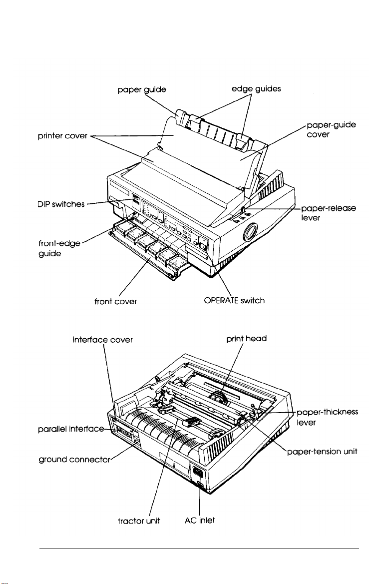
Printer Parts
Introduction 5
Page 24

Chapter 1
Setting Up the Printer
Unpacking the Printer . . . . . . . . . . . . . . . . . . . . . 1-2
Checking the parts . . . . . . . . . . . . . . . . . . . . . 1-2
Choosing a Place for the Printer . . . . . . . . . . . . . . . . . . 1-3
Assembling the Printer . . . . . . . . . . . . . . . . . . . . 1-4
Removing the protective materials . . . . . . . . . . . . . . . 1-4
Installing the ribbon cartridge . . . . . . . . . . . . . . . . . 1-5
Attaching the paper guide . . . . . . . . . . . . . . . . . . . . 1-9
Testing the Printer . . . . . . . . . . . . . . . . . . . . . . . . 1-10
Plugging in the printer . . . . . . . . . . . . . . . . . . . . 1-10
Running the self test . . . . . . . . . . . . . . . . . . . . .. 1-10
Connecting the Printer to Your Computer . . . . . . . . . . . . 1-13
Configuring Your Software for the Printer . . . . . . . . . . . . 1-15
Choosing from a menu . . . . . . . . . . . . . . . . . . . 1-15
Setting Up the Printer 1-1
Page 25
Unpacking the Printer
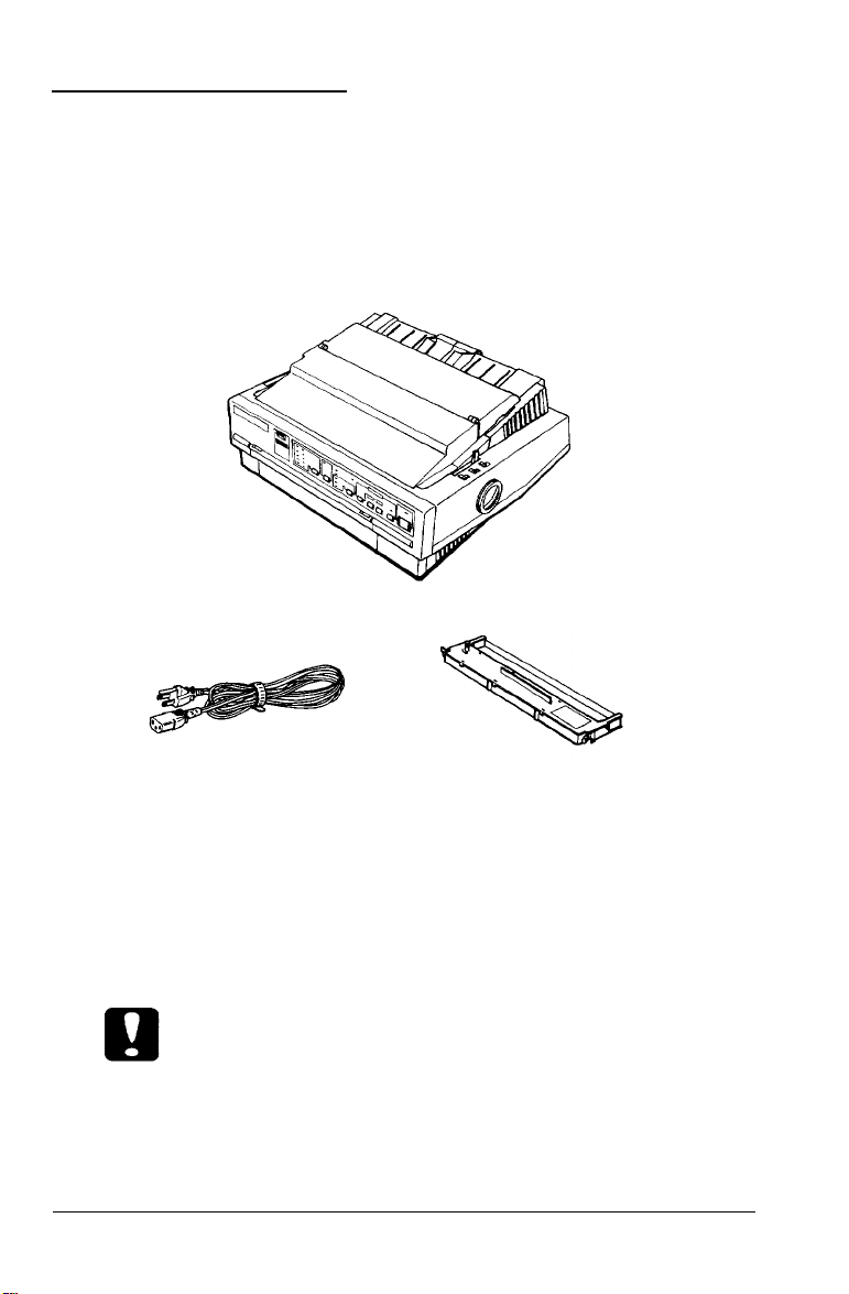
Checking the parts
When you unpack the printer, make sure you have all the parts
shown below and that none is damaged.
Printer
Power cord
Ribbon cartridge
Note:
In some locations the power cord may be attached to the printer.
Store the packing materials in case you ever need to transport
your printer.
Caution:
There are several versions of the printer designed for different
voltages, and it is not possible to adjust the printer for use at
another voltage. If the label on the back of the printer does not
show the correct voltage for your country, contact your dealer.
1-2 Setting Up the Printer
Page 26

Choosing a Place for the Printer
When selecting a place to set up your printer, be sure to follow
the guidelines below.
Place the printer on a flat, stable surface.
Place the printer close enough to the computer for the
printer's interface cable to reach it.
Leave adequate room around the printer to allow for easy
operation and maintenance.
Caution:
Avoid locations that are subject to direct sunlight, excessive
heat, moisture, or dust.
Use a grounded outlet; do not use an adapter plug.
Place the printer where you can easily unplug the power
cord.
Avoid electrical outlets controlled by wall switches or
automatic timers. Accidental disruption of power can wipe
out information in the memory of your printer or computer.
Avoid outlets on the same circuit as large motors or other
appliances that can cause fluctuations in line voltage.
Keep the entire computer system away from potential
sources of electromagnetic interference, such as
loudspeakers or the base units of cordless telephones.
Setting Up the Printer 1-3
Page 27

If you plan to use a printer stand, follow these guidelines:
Use a stand that supports at least 16.0 kg (35.3 lbs).
Never use a stand that tilts the printer at an angle of more
than 15 degrees from horizontal. If you install a cut-sheet
feeder, the stand must keep your printer level.
If you plan to load continuous paper through the bottom of
the printer, choose a stand that provides an unobstructed
paper path.
Position your printer’s power cord and interface cable so
they do not interfere with paper feeding. If possible, secure
the cables to a leg of the printer stand.
Align the paper stack so that the paper feeds straight into
the tractor’s sprocket units.
Assembling the Printer
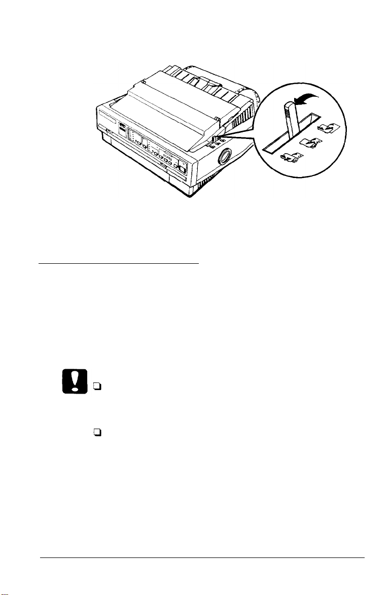
Removing the protective materials
During shipping, several pieces of packing material protect the
printer. Before you assemble the printer, you must remove
these protective materials as shown in the attached Notice
Sheet.
Note:
Store all protective materials in case you ever need to transport your
printer.
1-4 Setting Up the Printer
Page 28
Installing the ribbon cartridge
Before installing the ribbon cartridge, make sure that the
power cord is not plugged into an electrical outlet.
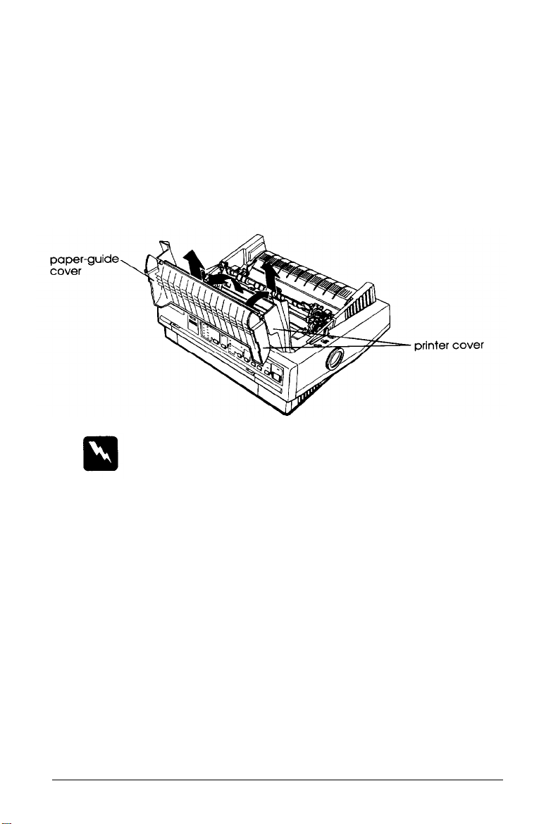
1. Raise the paper-guide cover and rest it on the printer cover.
Lift the paper guide up and off. Lift the printer cover up
and off. Grasp both ends of the clear plastic paper-tension
unit; lift up the front of the unit and then lift it off.
Warning:
Never move the print head while the printer is turned on; this
can damage the printer. Also, if you just used the printer, the
print head may be hot. Let it cool for a few minutes before
touching it.
Setting Up the Printer 1-5
Page 29
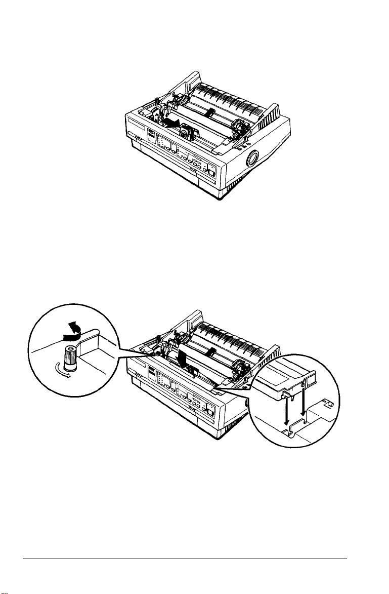
2. Slide the print head to the middle of the printer.
3.
Turn the ribbon-tightening knob in the direction of the
arrow. This removes any slack in the ribbon and makes it
easier to install. Next, hold the ribbon cartridge by its
handle and push it firmly down into position; then press
on both ends of the cartridge to make sure the plastic
hooks fit into the slots.
1-6 Setting Up the Printer
Page 30
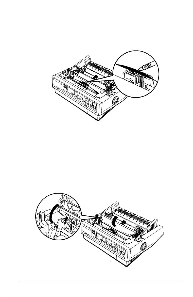
4.
Use a pointed object, such as a ball point pen, to guide the
ribbon between the print head and ribbon guide. Turn the
ribbon-tightening knob to help feed the ribbon into place.
Slide the print head from side to side to make sure it moves
5.
smoothly. Also check that the ribbon is not twisted or
creased.
Replace the paper-tension unit by placing it on the printer’s
6.
mounting pegs; then lower the front of the unit into place.
Press on the front of both sides of the paper-tension unit
until you feel it click into place.
Setting Up the Printer 1-7
Page 31

7.
Replace the printer cover by first inserting the front tabs into
the slots on the printer; then lower it into place.
Note:
You install the optional #7768 or #7770 film
as you install the ribbon cartridge. However,
guidelines below when using a film ribbon:
Print on ordinary paper only.
Move the paper-thickness lever to the next lowest position.
ribbons in the same way
you should follow the
1-8 Setting Up the Printer
Page 32

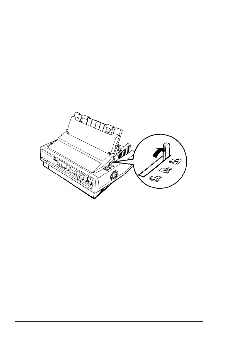
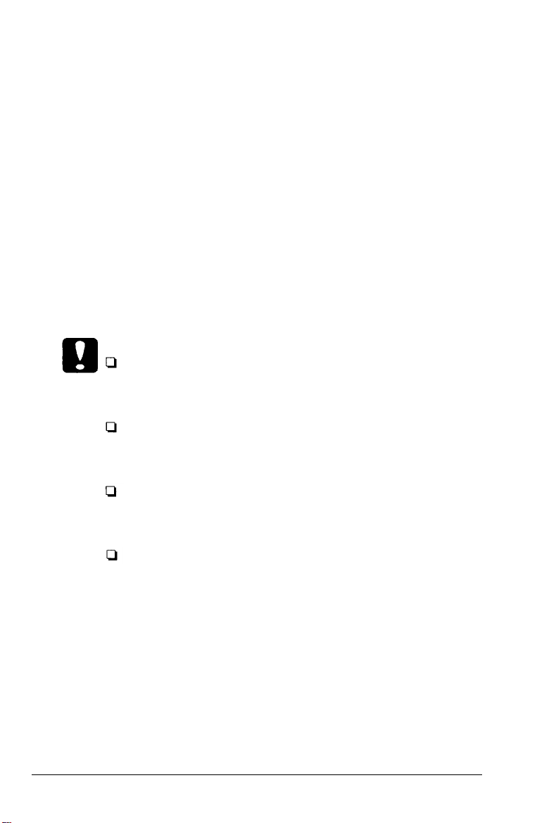
Attaching the paper guide
1. Place the notches on the paper guide straight down over the
mounting posts on the printer.
2. Lower the paper guide until it stops in the upright position.
Raise the paper guide cover and rest it against the paper
guide.
Setting Up the Printer 1-9
Page 33

Testing the Printer
Before connecting your printer to a computer, use the built-in
self-test function to see that the printer is working properly.
Before running the self test, you need to plug your printer’s
power cord into an electrical outlet.
Plugging in the printer
1. Make sure the printer is turned off.
2. Check the label on the back of the printer to make sure the
voltage required by the printer matches that of your
electrical outlet.
Caution:
If the rated voltage and your outlet voltage do not match,
contact your dealer for assistance. Do not plug
power
cord,
3. If the power cord is not attached to the printer, connect it to
the AC inlet on the printer’s rear panel.
in the
4.
Plug the power cord into a properly grounded electrical
outlet.
Running the self test
You can run the self test with either continuous paper or single
sheets. Also, you can load the paper for the test from the top,
rear, front, or bottom. The following steps describe how to run
the test on single-sheet paper, loaded from the top. See Chapter
2 for full details on paper handling.
1-10 Setting Up the Printer
Page 34

By holding down a certain button while you turn on the
printer, you can perform the self test in draft or LQ mode, or
you can print out a list of the current DIP-switch settings.
These buttons are listed below:
LOAD/EJECT
LF/FF
ALT
Draft mode self test
LQ mode self test
DIP-switch setting list
The self test begins by printing on the first and last lines of
page 1. The printer then prints the character samples on page 2.
If you select LQ mode, the printer prints the self test in every
font, in turn.
1. Make sure the printer is turned off and that the paper-release
lever is in the single-sheet position.
2. While holding down the appropriate button, turn on the
printer. The printer beeps and the platen turns for a few
seconds, signaling that the printer is in self-test mode.
Setting Up the Printer 1-11
Page 35

3. Move the left edge guide until it locks in place next to the
guide mark. Then adjust the right edge guide to match the
width of your paper.
Caution:
Run the self test using paper at least 210 mm (8.2 inches)
wide; otherwise, the print head prints directly on the platen.
4. Insert a sheet of paper between the edge guides until it meets
resistance. After a few seconds, the printer loads the paper
to the loading position and begins printing the self test.
1-12 Setting Up the Printer
Page 36

5. To stop the self test, press the
the self test by pressing the
PAUSE
PAUSE
button again).
button (you can resume
6. Press the
printer and then turn the printer off.
If test results are not satisfactory, see Chapter 6.
Here is part of a typical self test in LQ mode.
LOAD/EJECT
button to eject the paper from the
Connecting the Printer to Your Computer
If the self test prints correctly, you are ready to connect your
printer to the computer. Use a shielded twisted-pair parallel
cable to connect your computer to the printer’s built-in parallel
interface.
Setting Up the Printer
1-13
Page 37

Connect the parallel interface cable as described below:
1. Make sure both the printer and computer are turned off; then
plug the cable connector securely into the printer’s parallel
interface connector. Squeeze the wire clips together until
they lock in place on either side of the connector.
Note:
If your cable has a ground wire, connect it to the ground connector
beside the in interface connector.
2. Plug the other end of the cable into the computer. (If there is
a ground wire at the computer end of the cable, attach it to
the ground connector at the back of the computer.)
1-14 Setting Up the Printer
Page 38

Configuring Your Software for the Printer
Most software lets you specify the type of printer you use so
that you can take full advantage of the printer's features. Your
software probably provides an installation or setup section that
presents a list of printers.
Choosing from a menu
To take full advantage of your printer’s features, including
ESC/P 2, choose the LQ-570+ or Stylus 800 from the menu. If
these printers are not listed, contact the software manufacturer
or see “Where to Get Help for United States Users” at the
beginning of this manual to see if an update to the software is
available. Until you receive an update, choose from the
following list:
Action Printer 5000+
Action Printer 5000
LQ-570/1070
LQ-870/1170
LQ-100
SQ-870/l170
LQ-510/550
LQ-500
LQ-860 (LQ-1060)
LQ-850 (LQ1050)
LQ-2550
If none of these printers is listed, select the first one available
from the following list: LQ, FX, LX, RX, MX, Epson printer,
Standard printer, Draft printer. Because the printers in this list
are 9-pin printers, your graphics printing may not be correct.
Setting Up the Printer
1-15
Page 39

Chapter 2
Paper Handling
Selecting a Paper Feeding Method. . . . . . . . . . . . . . . . . 2-2
Setting the paper-release lever . . . . . . . . . . . . . . . . . 2-2
Using Single Sheets . . . . . . . . . . . . . . . . . . . . . . . 2-4
Loading single sheets from the top . . . . . . . . . . . . . . . 2-4
Loading single sheets from the front . . . . . . . . . . . . . . 2-6
Using Continuous Paper . . . . . . . . . . . . . . . . . . . 2-8
Tractor position and available paper paths . . . . . . . . . . 2-9
Changing tractor positions . . . . . . . . . . . . . . . . . . . 2-9
Loading continuous paper with the push tractor . . . . . . . 2-12
Removing continuous paper from the push tractor . . . . . 2-15
Loading continuous paper with the pull tractor . . . . . . . 2-15
Removing continuous paper from the pull tractor . . . . . . 2-20
Switching Between Continuous Paper and Single Sheets . . . 2-21
Switching to single sheets . . . . . . . . . . . . . . . . . . . . 2-21
Switching to continuous paper . . . . . . . . . . . . . . . . . 2-22
Printing on Special Paper.... . . . . . . . . . . . . . . . . . . 2-23
Paper-thickness lever . . . . . . . . . . . . . . . . . . . . 2-24
Multi-part forms . . . . . . . . . . . . . . . . . . . . . . 2-25
Labels . . . . . . . . . . . . . . . . . . . . . . . . . . . . . 2-26
Envelopes . . . . . . . . . . . . . . . . . . . . . . . . . . 2-27
Paper Handling 2-1
Page 40

Selecting a Paper Feeding Method
Your printer can feed single sheets from the top and front and
continuous paper from the rear, front, and bottom. Also, you
can use the tractor unit for continuous paper as either a push
or pull tractor.
You will probably use only one or two of these methods on a
regular basis.
This chapter explains the various methods of paper handling
and includes recommendations on the feeding methods best
suited to your specific needs.
Setting the paper-release lever
The paper-release lever has three positions, with icons
indicating the type of paper and paper path for each position.
2-2 Paper Handling
Page 41

Single sheet This position is for loading single sheets.
Push tractor
Pull tractor
This position is for loading continuous paper from
the rear, with the tractor in the push-tractor
position.
This position is for loading continuous paper from
the rear, front, or bottom, with the tractor in the
pull-tractor position. Use this position when
you have installed both the push tractor and
the optional pull tractor.
Paper Handling 2-3
Page 42
Using Single Sheets
Your printer can print on single sheets of paper from 148 mm
(5.8 inches) to 257 mm (10.1 inches) wide. You can load single
sheets from either the top or front of the printer.
Loading single sheets from the top
1. Move the paper-release lever to the single-sheet position.
Make sure the paper guide is in the upright position.
2.
Turn on the printer. The OPERATE light on the control panel
comes on.
2-4 Paper Handling
Page 43

3.
Slowly slide the left edge guide until it stops next to the
arrow on the paper guide. Then adjust the right edge guide
to match the width of your paper.
4.
Insert the paper firmly between the edge guides until it meets
resistance; after a few seconds, the printer automatically
advances the paper to the loading position.
Paper Handling 2-5
Page 44

Caution:
Use the knob on the right side of the printer only to clear paper
jams when the printer is off. Otherwise, you may damage the
printer or cause it to lose the top-of-form position.
If the platen turns but the printer doesn’t load the paper,
completely remove the paper and re-insert it more firmly.
To eject the paper, press the LOAD/EJECT button.
Loading single sheets from the front
1. Move the paper-release lever to the single-sheet position and
open the front cover.
2. Turn on the printer. The
comes on.
2-6 Paper Handling
OPERATE
light on the control panel
Page 45
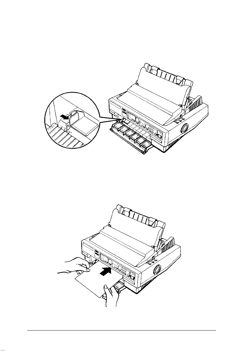
3. Slide the edge guide until you feel it click into place at the
guide mark. You can slide the edge guide to the left in
1/l0-inch increments to increase the size of the left margin
on your paper.
4.
While aligning the paper’s left edge with the edge guide,
insert the paper firmly until it meets resistance; after a few
seconds, the printer automatically loads the paper to the
loading position.
Paper Handling 2-7
Page 46

Caution:
Use the knob on the right side of the printer only to clear paper
jams when the printer is off. Otherwise, you may damage the
printer or cause it to lose the top-of-form position.
If the
platen turns but the printer doesn’t load the paper,
completely remove the paper and re-insert it more firmly.
To eject the paper, press the
LOAD/EJECT
button.
Note:
The printer’s built-in stacker in front of the paper guide can hold up to
50 sheets of ejected paper.
Using Continuous Paper
You can print on continuous paper from 101 mm
254 mm (10 inches) wide.
You can feed continuous paper from the rear, front, or bottom.
Your printer comes with the tractor installed in the
push-tractor position, for feeding paper from the rear. If this is
your paper-feeding method, skip to page 2-12. To feed paper
from the front or bottom, you must install the tractor in the
pull-tractor position. You can also install an optional pull
tractor and use both the push and pull tractors together.
(4
inches) to
2-8 Paper Handling
Page 47
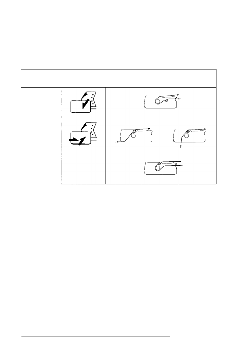
Tractor position and available paper paths
Below are the various ways of feeding continuous paper.
Always move the paper-release lever to the position indicated
for the paper-feeding method you are using.
Tractor
position lever position
Push-tractor
position
Pull-tractor
position
Paper-release
Paper-feeding method
Make sure you align your paper supply with the paper loaded
in the tractor so the paper feeds smoothly into the printer.
If you want to feed paper through the bottom paper slot, use a
printer stand that has a large enough opening for paper to feed
from the bottom without obstruction.
Changing tractor positions
You can use the tractor unit as either a push tractor or a pull
tractor. You can change the tractor position according to your
paper feeding method. The printer comes with the tractor
installed in the push-tractor position.
Paper Handling 2-9
Page 48
Installing in the push-tractor position
1.
Make sure the printer is turned off. Lift the printer cover and
the paper guide up and off the printer.
If necessary, remove the tractor from the pull-tractor position
2.
by pressing the lock tabs open while lifting the tractor up
and out of the mounting slots.
Press open the tractor’s lock tabs. Hold the tractor
3.
horizontally above the printer and lower it straight down
into the printer’s back mounting slots.
When the tractor is positioned in the mounting slots, release
4.
the lock tabs.
If you removed the clear plastic paper-tension unit
5.
previously, replace it by placing it on the printer’s
mounting pegs; then lower into place. Press on both ends
of the paper-tension unit until you feel it click into place.
Replace the printer cover.
6.
7.
Move the paper-release lever to the push-tractor position.
You are now ready to load continuous paper with the push
tractor. See page 2-12 for instructions.
2-10
Paper Handling
Page 49

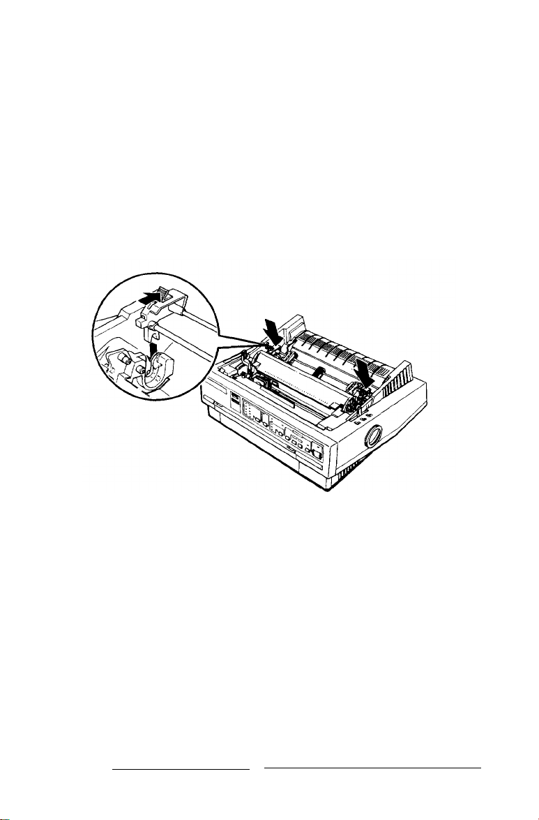
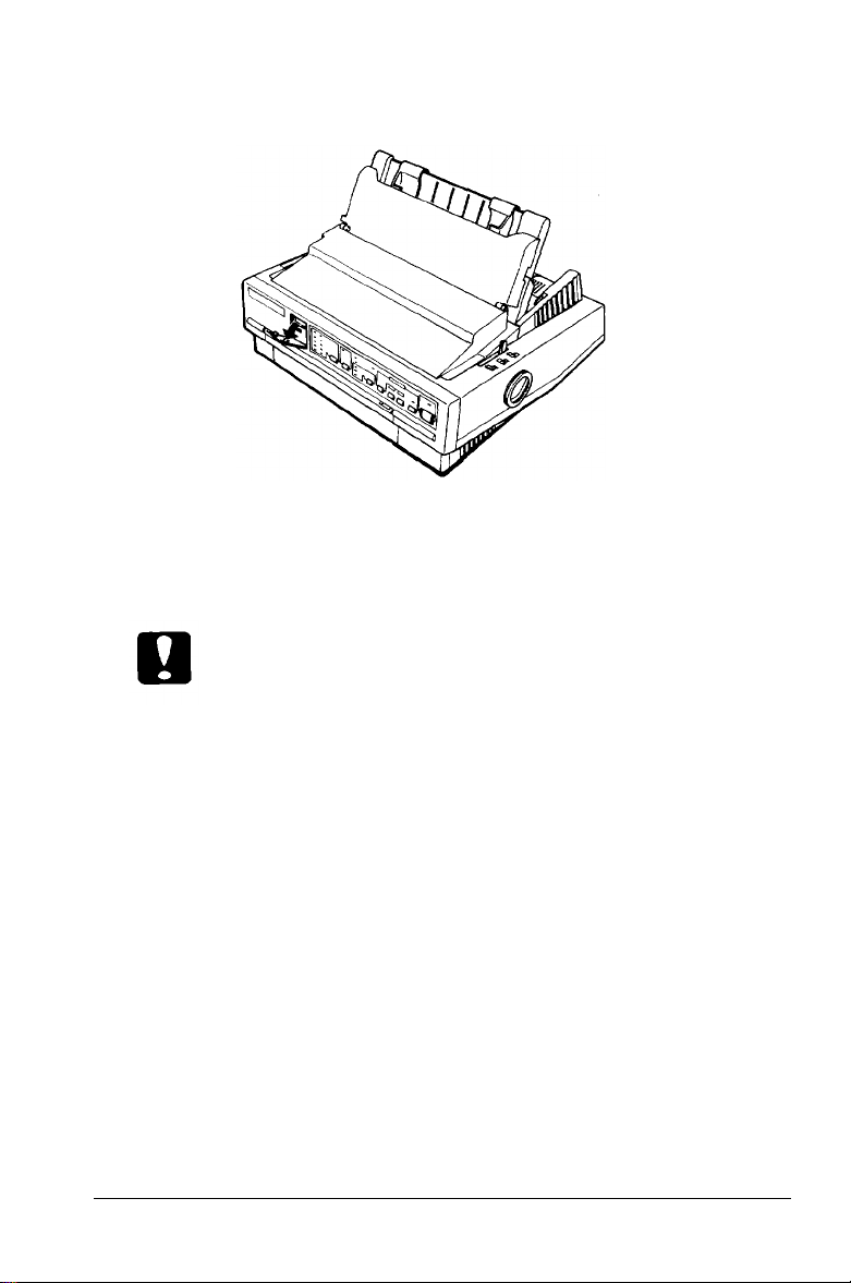
Installing in the pull-tractor position
Make sure the power is turned off. Remove the paper guide.
1.
Raise the paper-guide cover and rest it on the printer cover.
Lift the printer cover up and off.
Grasp both ends of the clear plastic paper-tension unit and
2.
lift it up from the front and lift it off the printer.
If necessary, remove the tractor from the push-tractor
3.
position by pressing the lock tabs open while lifting the
tractor up and out of the mounting slots.
Push the tractor’s lock tabs into the open position. Tilt the
4.
tractor forward and lower it into the printer’s front
mounting slots. An arrow on each side of the mounting
slots shows you where to align the tractor.
When the tractor is positioned in the mounting slots
5.
the lock tabs.
Pull the paper-release lever forward to the pull-tractor
6.
position.
You are now ready to load continuous paper. See page 2-15 for
instructions.
Paper Handling
, release
2-11
Page 50

Loading continuous paper with the push tractor
1. Make sure the printer is turned off, the paper-guide cover is
resting on the printer cover, and the paper guide is
removed.
2. Make sure the tractor is in the push-tractor position and the
paper-release lever is in the push-tractor position.
3. Release the tractor’s sprocket units by pulling the sprocket
lock levers forward.
2-12 Paper Handling
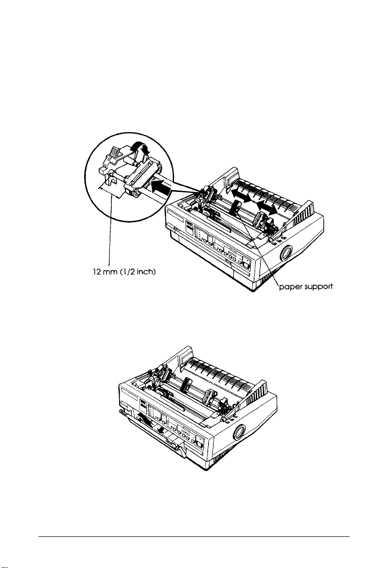
Page 51

4. Slide the left sprocket unit to approximately 12 mm (½ inch)
from the far left position and push the sprocket lock lever
back to lock it in place. Then slide the right sprocket unit to
match the width of your paper, but do not lock it. Move the
paper support so it is midway between the sprocket units.
5. Make sure your paper has a clean, straight leading edge.
Then open the sprocket covers and fit the first four holes of
the paper over the sprocket pins.
Paper Handling
2-13
Page 52

6.
Close the sprocket covers.
7.
Slide the right sprocket unit to remove any slack in the paper.
Then lock it in place by pushing the sprocket lock lever
back.
8.
Place the notches on the paper guide straight down over the
mounting posts on the printer.
Slightly lift the paper guide and then lower it until it rests on
9.
the printer. Raise the paper-guide cover and rest it on the
paper guide.
10. Slide both edge guides to the middle of the paper guide.
11. Turn on the printer. The printer automatically advances the
paper to the loading position when it receives data.
Note:
You can also advance the paper to the loading position by pressing the
LOAD/EJECT button.
Caution:
Use the knob on the right side of the printer only to clear paper
jams when the printer is off. Otherwise, you may damage the
printer or cause it to lose the top-of-form position.
2-14 Paper Handling
Page 53

Removing continuous paper from the push tractor
1. Press the
TEAR OFF
button to advance the paper to the
tear-off position. (See Chapter 3 for more information.)
Tear off any printed sheets.
Caution:
Always tear off paper before back-feeding; back-feeding too
many sheets can cause a paper jam.
2. Press the
LOAD/EJECT
button to feed the paper back to the
standby position.
3. Remove the paper from the tractor unit.
Loading continuous paper with the pull tractor
By placing the tractor in the pull-tractor position, you can load
paper from the rear, front, or bottom. The steps are the same
for all paper paths.
Note:
When the tractor is in the pull-tractor position, do not use the
TEAR-OFF
fo the standby position.
button or the
LOAD/EJECT
button to feed the paper back
1. Make sure the printer is turned off and the paper guide and
the printer cover are removed.
Paper Handling
2-15
Page 54

2. Make sure the tractor is in the pull-tractor position and the
paper-release lever is in the pull-tractor position.
3.
Release the tractor’s sprocket units by pulling the sprocket
lock levers forward.
2-16 Paper Handling
Page 55
4. Slide the left sprocket unit to approximately 12 mm (½ inch)
from the far left position and push the sprocket lock lever
back to lock the sprocket unit in place. Then slide the right
sprocket unit to match the width of your paper, but do not
lock it in place. Move the paper support so it is midway
between the sprocket units.
5.
If you are inserting paper in the front paper slot, remove the
front cover and slide the edge guide completely to the left.
Paper Handling
2-17
Page 56

6.7.Make sure your paper has a clean, straight edge. Insert the
paper into the desired paper slot (rear, front, or bottom)
until it emerges between the platen and print head.
Pull the paper up until the perforation between the first and
. .
second pages is even with the top of the printer’s ribbon.
8. If you insert paper through the front paper slot, re-attach the
front cover.
2-18 Paper Handling
Page 57

9. Fit the first four holes of the paper over the sprocket pins.
10. Close the sprocket covers.
11. Slide the right sprocket unit to remove any slack in the
paper. Then lock it in place by pushing the sprocket lock
lever back.
12. Place the notches on the paper guide straight down over the
mounting posts on the printer.
13. Slightly lift the paper guide and then lower it until it rests
on the printer.
14. Slide both edge guides to the middle of the paper guide.
15. Turn on the printer.
Paper Handling
2-19
Page 58

16. If necessary, adjust the paper position using the micro-feed
feature described in Chapter 3.
Caution:
Use the knob on the right side of the printer only to clear paper
jams when the printer is of. Otherwise, you may damage the
printer or cause if to lose the top-of-form position.
17. To replace the printer cover, insert the front tabs into the
slots on the printer and then lower the cover into place.
Raise the paper-guide cover and rest it on the paper guide.
Removing continuous paper from the pull tractor
1. To remove continuous paper when using the pull tractor, tear
off the paper at a point before it enters the paper slot.
2. Press the LF/FF button to feed the remaining paper forward,
out of the printer.
2-20 Paper Handling
Page 59

Switching Between Continuous Paper and Single
Sheets
When using the push tractor, you can easily switch to
single-sheet printing without removing the continuous paper.
Switching to single sheets
To switch from continuous paper to single sheets, follow the
steps below.
1. If any printed sheets remain in the printer, press the
TEAR OFF
position.
2. Tear off the printed pages.
Caution:
Never back-feed labels. Labels can easily come off their
button to advance the paper to the tear-off
Always fear off paper before back-feeding; back-feeding too
many sheets an cause a paper jam.
backing and jam the printer.
3. Press the LOAD/EJECT button. The printer feeds the
continuous paper backward to the standby position. The
paper is still attached to the push tractor but is no longer in
the paper path.
Paper Handling
2-21
Page 60

4.
Move the paper-release lever to the single-sheet position.
5. Lift the paper guide until it stops in the upright position.
6. Adjust the edge guides to match the width of your paper.
You can now load single sheets as described in “Using Single
Sheets” in this chapter.
Switching to continuous paper
To switch from single sheets back to continuous paper in the
push tractor, follow the steps below.
1.
If a single sheet is in the paper path, press the
button to eject it.
2.
Slightly lift the paper guide and then lower it until it rests on
the printer.
3.
Slide both edge guides to the middle of the paper guide.
2-22 Paper Handling
LOAD/EJECT
Page 61
4.
Move the paper-release lever to the push-tractor position.
The printer automatically advances the continuous paper to
the loading position when it receives data.
Printing on Special Paper
In addition to printing on single sheets and continuous paper,
your printer can print on a wide variety of other paper types,
such as envelopes, labels, and multi-part forms. Before printing
on special types of paper, you need to change the
paper-thickness setting.
Caution:
When printing on labels or multi-part forms, make sure
that your software settings keep the printing entirely
within the printable area.
Always return the paper-thickness lever to position 0 when
you return to printing on ordinary paper.
Paper Handling
2-23
Page 62

Paper-thickness lever
Set the paper-thickness lever to match the thickness of your
paper according to the table below.
Paper Type
Ordinary paper (with film ribbon)
Thin paper
Ordinary paper (single sheets or continuous)
Multi-part forms (carbonless)
2 sheets (original + 1 copy)
Lever Position
0
3 sheets (original + 2 copies)
4 sheets (original + 3 copies)
Envelopes
Note:
Print speed is reduced for paper-thickness lever settings of 2 and above.
2-24 Paper Handling
-1
-1 or 0
1
2
2 to 3
2
2 to 5
Page 63

Multi-part forms
Your printer can print on both single-sheet and continuous
multi- part forms. You can load single-sheet multi-part forms
only in the front paper slot.
You can use multi-part forms of up to four parts (including the
original). Make sure you set the paper-thickness lever to the
proper position. Use only carbonless multi-part forms.
You load multi-part forms the same way as you load single
sheets or continuous paper. For best results with continuous
multi-part forms, it is recommended you use the tractor
installed in the push-tractor position together with the optional
pull tractor.
For details, see “Using Single Sheets” or “Loading continuous
paper with the pull tractor,” earlier in this chapter. Pay special
attention to setting the loading position as described in “Using
micro-feed” in Chapter 3.
Caution:
When printing multi-part forms, make sure the printing
stays entirely within the printable area of the forms. (For
more information on the printable area, see Chapter 7.)
Use four-part multi-part forms only under normal
operating conditions.
Load single-sheet multi-part forms from the front only.
Paper Handling
2-25
Page 64
Labels
When printing labels, always choose the type mounted on a
continuous backing sheet with sprocket holes for use with a
tractor. Do not try to print labels as single sheets because labels
on a shiny backing sheet do not feed properly.
It is recommended you load labels from the front or bottom
paper slots with the tractor in the pull-tractor position. You
load labels the same way that you load continuous paper (with
the pull tractor), except you set the paper-thickness lever to
position 2.
See “Loading continuous paper with the pull tractor” earlier in
this chapter for details.
Caution:
Never feed labels backward with the LOAD/EJECT or
TEAR OFF buttons. Labels can easily peel off the backing
and jam the printer.
Since labels are especially sensitive to temperature and
humidity, use them only under normal operating
conditions.
Do not leave labels loaded in the printer between jobs; they
curl around the platen and may jam when you resume
printing.
To remove labels from the paper path after you finish
printing, first tear off the labels at a point before the paper
slot. Then use the LF/FF button to advance the remaining
labels out of the printer.
2-26 Paper Handling
Page 65

Envelopes
You can load envelopes from the top just like single-sheet
paper. However, you should pay attention to the guidelines
below:
Always set the paper-thickness lever to position 2, 3, or 4
depending on the thickness of the envelope.
Always feed an envelope by pushing the wide edge into
the printer until it meets resistance.
Caution:
Only use envelopes under normal operating conditions.
Printing on the edge of an envelope can damage the print
head. Make sure the printing stays entirely within the
printable area of the envelopes. (See page 7-5.)
Paper Handling
2-27
Page 66

Chapter 3
Using the Printer
Control Panel . . . . . . . . . . . .
Lights . . . . . . . . . . . . . . .
Buttons . . . . . . . . . . . . . .
Other control-panel features .
DIP Switches . . . . . . . . . . . .
Changing a DIP-switch setting
DIP-switch tables . . . . . . . .
DIP-switch functions . . . . . .
Micro-Feed . . . . . . . . . . . . .
Using micro-feed . . . . . . . .
Adjusting the loading position
Tear Off . . . . . . . . . . . . . . .
Tear-off mode . . . . . . . . . .
Using the TEAR OFF button . .
Adjusting the tear-off position
Typestyles . . . . . . . . . . . . . .
Character fonts . . . . . . . . .
Character spacing . . . . . . . .
Condensed printing . . . . . .
Data Dump Mode. . . . . . . .
. . . . . . . . . . . . . . . . .
. . . . . . . . . . . . . . . . .
. . . . . . . . . . . . . . . . .
. . . . . . . . . . . . . . . . .
. . . . . . . . . . . . . . . . .
. . . . . . . . . . . . . . . . .
. . . . . . . . . . . . . . . . .
. . . . . . . . . . . . . . . . .
. . . . . . . . . . . . . . . . .
. . . . . . . . . . . . . . . . .
. . . . . . . . . . . . . . . . .
. . . . . . . . . . . . . . . . .
. . . . . . . . . . . . . . . . .
. . . . . . . . . . . . . . . . .
. . . . . . . . . . . . . . . . .
. . . . . . . . . . . . . . . . .
. . . . . . . . . . . . . . . . .
. . . . . . . . . . . . . . . . .
. . . . . . . . . . . . . . . . .
. . . . . . . . . . . . . . . . .
3-2
3-2
3-4
3-5
3-6
3-6
3-8
3-10
3-14
3-14
3-15
3-17
3-17
3-18
3-19
3-20
3-20
3-25
3-26
3-26
Using the Printer 3-1
Page 67

Control Panel
The indicator lights give you the current status of the printer.
The buttons let you control many printer settings.
Lights
OPERATE
On when the operate switch is on and power is supplied.
PAUSE
On when the printer is not ready to print data. The
is off unless you press the pause button to prevent printing.
DATA
On when the printer’s buffer contains data,
MULTI-PART
On when you move the paper-thickness lever to position 2 or
higher. The printing speed is reduced when this light is on.
When this light is flashing, you can use the micro-feed feature.
3-2 Using the Printer
(green)
(orange)
PAUSE
(orange)
(green)
light
Page 68

PAPER OUT
(red)
On when the printer runs out of paper.
BIN 1
(green)
On when bin 1 of the optional cut-sheet feeder is selected for
paper feeding.
BIN 2
(green)
On
when bin 2 of the optional cut-sheet feeder is selected for
paper feeding.
TEAR OFF
On when you press the
(yellow)
TEAR OFF
button to feed continuous
paper to the tear-off position.
CONDENSED
(green)
On when you select condensed printing from the control panel.
FONT
(green)
On when a specific font is selected. When you select Roman T
or Sans Serif H with your software, all the FONT lights are
turned off
Using the Printer 3-3
Page 69

Buttons
PAUSE
Press this button to temporarily stop printing. Press this button
again to resume printing.
LOAD/EJECT
Press this button to load single-sheet or continuous paper to
the loading position. However, the printer normally loads
paper automatically. If single-sheet paper is already in the
loading position, use this button to eject the sheet. If
continuous paper is in the loading or tear-off position, press
this button to feed it backward to the standby position.
LF/FF
(line feed/form feed)
Press this button briefly to feed the paper forward one line.
Hold this button down to eject a single sheet of paper or
advance continuous paper to the top of the next page. You can
also use this button to load a single sheet of paper from the
cut-sheet feeder or to feed continuous paper from the standby
position to the loading position.
ALT
Use this button in combination with other buttons to perform
the following tasks:
BUFFER CLEAR (PAUSE)
Clears the printer’s buffer and
initializes the printer settings.
Note:
To clear the buffer but save the top-of-form setting, press the PAUSE
button; then press the
the next page; and then press the
time.
LF/FF button to advance the paper to the top of
ALT and PAUSE buttons at the same
3-4 Using the Printer
Page 70

MICRO FEED (LOAD/EJECT)
Feeds paper forward in
1/180-inch increments.
MICRO FEED (LF/FF)
Reverse-feeds paper in 1/180-inch
increments.
See “Micro-Feed” later in this chapter for more information on
using the button.
Bin Select/TEAR OFF
This button selects the paper bin when both optional cut-sheet
feeders are installed and you are printing on single sheets.
When printing on continuous paper, press this button once to
feed paper from the loading position to the tear-off position.
Press this button again to feed the paper backward to the
loading position.
CONDENSED
Press this button to print condensed characters. Press it again
to return to normal character printing.
FONT
Press this button to select from among the built-in fonts.
You cannot select Roman T or Sans Serif H with this button.
You can select these fonts only with your software.
Note:
The typestyle samples on the panel are meant as guides only; actual
printed results may differ slightly.
Other control-panel features
The control panel also gives you access to the two other special
functions.
Using the Printer 3-5
Page 71

Self test:
Hold down the LF/FF button (for LQ printing) or the
LOAD/EJECT button (for draft printing) while
turning on the printer. The self test lets you
check that your printer is operating properly.
Hold down the ALT button while turning on the
printer to print out a list of the current
DIP-switch settings.
See the section on testing the printer in Chapter
1 for more information.
Data dump:
Hold down the LF/FF and LOAD/EJECT buttons
while turning on the printer to enter data
dump mode. Data dump mode allows
advanced users to find the cause of
communication problems between the printer
and the computer.
The data dump mode is more fully explained at
the end of this chapter.
DIP Switches
By setting the printer’s two sets of DIP switches, you can
control various printer features, such as the graphics character
set and page length. New settings take effect whenever the
printer is turned on. The DIP switches are located inside the
compartment next to the control panel.
Changing a DIP-switch setting
To change a DIP-switch setting, follow these steps:
1. Turn off the printer.
3-6 Using the Printer
Page 72
2. Open the DIP-switch cover on the front panel.
3. Use a pointed instrument, such as the tip of a pen, to turn a
switch on or off. The section on DIP-switch functions lists
the setting for each switch.
Caution:
Do not use a pencil tip to change a DIP-switch setting. The tip
may break off and damage the switch.
Close the DIP-switch cover.
4.
The new DIP-switch settings take effect when you turn on the
printer.
Using the Printer 3-7
Page 73

DIP-switch tables
The tables below list the functions of the DIP switches. You can
see the current DIP-switch settings at any time by running the
self test as described in Chapter 1.
DIP switch 1
** SW 1-6 has no function on printers other than the European version.
DIP switch 2
* The asterisks indicate the default or factory settings, The defaults for DIP
switches 1-1, 1-2, 1-3, 1-4, 2-1, and 2-2 vary according to the country,
3-8 Using the Printer
Page 74

International character sets
Country
USA
France
Germany
United Kingdom On
Denmark
Sweden
Italy
Spain I
Character tables
Character Table
Italic
PC 437 (United States)
PC 850 (Multilingual)
1-1
On On On
On
On
Oft
off
Off
Off
1-2 1-3
On
Off
Off Off
On
On
Off
Off
1-1
Set the international
character set according
to the table above.
On On On
On On
Off
On
On
Off
On
Off
1-2 1-3 1-4
Off
1-4
Off
Off
Off
Off
Off
Off
Off
Off
Off
On
On
PC 860 (Portugal)
PC 863 (Canada-French)
PC 865 (Norway)
BRASCII (Brazilian Portuguese)*
PC 437 Greek**
Abicomp (Brazilian Portuguese)*
PC 853 (Turksh)**
PC 437 (United States)*
PC 852 (East Europe)**
* These character tables are not available on the European version,
** These character tables are available only on the European version,
On
On
off
Off
Off
Off Off Off
off
off
On
On
Off
On
off
On
Off
On On
Using the Printer 3-9
On
On
On
On
On
Page 75

Page length
Page length
8.5 inches (216 mm) Off On
11 inches (279 mm) Off
11.7 inches (296 mm)
12 inches (305 mm)
2-1
On
On
2-2
Off
On
Off
DIP-switch functions
This section describes the functions of the DIP switches.
International character sets
You can choose from eight international character sets by
setting DIP switches 1-1, 1-2, 1-3, and 1-4 according to the
“International character sets” table on page 3-19. See the
Appendix for character samples.
The character sets you can select by DIP switch are USA,
France, Germany, United Kingdom, Denmark I, Sweden, Italy,
and Spain I. However, you can select the following sets only
with the ESC R software command: Japan (English), Norway,
Denmark II, Spain II, Latin America, Korea, and Legal.
Note:
If you send the ESC t 0 command (to select italics) while DIP switch
1-4 is on, the international character set is always USA.
Character tables
Your printer has either 13 (for the European version) or 8 (for
other versions) built-in character tables: 1 italics table and 12
(for the European version) or 7 (for other versions) graphics
character tables.
3-10 Using the Printer
Page 76

You can select the character tables with DIP switches 1-1, 1-2,
1-3, and 1-4, according to “Character tables” on page 3-9.
To select a graphics character table, you must first turn DIP
switch 1-4 on.
Note:
If you send the ESC t 1 command (to select graphics) while DIP
switch 1-4 is off, the graphics character table is
(United States).
always PC 437
All character tables are included in the Appendix.
Print direction
Printing is normally bidirectional. However, turning DIP
switch 1-5 on for unidirectional printing-in which the print
head prints in one direction only—allows for precise vertical
printing alignment. This makes it ideal for printing graphics
such as lines or boxes.
If DIP switch 1-5 is on, printing is unidirectional even if you
select bidirectional with the ESC U 0 software command.
Printer mode
This feature is available only on the European version of this
printer.
When DIP switch 1-6 is off, the printer operates in ESC/P2
mode. By setting the DIP switch to on, the printer operates in
IBM emulation mode. In this mode, the printer emulates an
IBM Proprinter X 24E. All the commands available on this IBM
printer are available in this mode, except one: Define
User-Defined Characters (ESC =).
Using the Printer 3-11
Page 77

In IBM emulation mode, the functions of some DIP switches
differ from those listed on pages 3-8 to 3-10. These functions
are listed in the following tables.
DIP-switch settings for IBM emulation mode
SW
1-1
1-2
1-3
1-4
1-8
2-l
2-2
* The asterisks indicate the default or factory settings, The defaults for DIP
switches 1-1, 1-2, 1-3, 1-4, 2-1, and 2-2 vary according to the country,
Description
Code page selection
Character set selection Set 2
Alternate graphic mode”’
Page length for continuous
paper
Auto CR enabled disabled
On
See table below
On
12 in. 11 in.
Off
Set 1
Off*
* * With SW 1-8 On, ESC 3, ESC A, ESC J, and ESC ☛ function the same as in
ESC/P.
Code page selection
Code pages
437
850
1-1
On On On
On
1-2
On Off
1-3
3-12
860
863 On
865
437 Greek
853
852
On
Off
Off
Off Off
Off Off Off
Using the Printer
Off
Off Off
On
On
On
On
Off
On
Page 78

Input buffer
The printer stores data sent from your computer in its input
buffer. Keep DIP switch 1-7 off to select an 8 KB buffer.
capacity
Skip-over-perforation
Turning DIP switch 1-8 on when you are using continuous
paper enables the skip-over-perforation function. Use this
function to leave a l-inch (25.4-mm) margin between the last
printable line on one page and the first printable line on the
next page. This causes the printer to skip over the perforation
between continuous sheets.
Most application programs take care of the top and bottom
margins. Do not turn on skip-over-perforation unless your
program does not provide these margins.
Adjust your top-of-form position with the
buttons to get half of the margin at the bottom of one page and
half at the top of the next page.
Continuous-paper page
When you are printing on continuous paper, DIP switches 2-1
and 2-2 let you select from the four page lengths described in
the “Page length" table on page 3-10.
length
MICRO FEED
Tear off
You can turn on DIP switch 2-3 to select tear-off mode. See
“Tear off" later in this chapter for information on the tear-off
mode. Use the tear-off feature only with continuous paper
loaded with the push tractor; do not use the tear-off feature
with the pull tractor.
Using the Printer 3-13
Page 79

Auto line feed
When auto line feed is on (DIP switch 2-4 on), the printer
accompanies each carriage-return code (CR) received with a
line-feed code (LF).
If your printer is double spacing, turn DIP switch 2-4 off. If
each line overprints the next, turn DIP switch 2-4 on.
Micro-Feed
The micro-feed feature allows you to move the paper forward
or backward in 1/180-inch increments. You can use this
feature to adjust the loading and tear-off positions.
Before you adjust the loading position, it is set to the factory
setting (8.5 mm). By moving the paper backward, you can set
the loading position to as high as 5.3 mm from the top edge of
the paper. You can then print more lines per page.
When you make adjustments to the loading or tear-off
positions with continuous paper, the printer remembers the
new position, even if you turn off the printer.
When you adjust the loading position of single-sheet paper, the
printer remembers the new position until you turn off the
power. The loading position returns to the factory setting
(8.5
mm) when
the power is turned on again.
Using micro-feed
To use the micro-feed feature, you press the
same time as you press the LOAD/EJECT or LF/FF button, as
indicated on the printer’s control panel. To use the micro-feed
feature, follow the steps below:
1. Make sure printing has stopped. If necessary, lift the printer
cover up so you can see the paper position.
3-14 Using the Printer
ALT
button at the
Page 80

2. While holding down the ALT button, press the LOAD/EJECT
button to feed the paper forward or the
feed the paper backward, as indicated by the arrows above
the buttons.
LF/FF
button to
Adjusting the loading position
The loading position is the position of the paper after it has
been automatically loaded by the printer. If printing is too high
or low on the page, change the loading position with the
micro-feed feature as follows:
1.
Make sure the printer is turned on. If necessary, lift the
printer cover up so you can see the paper position.
2. Load either continuous or single-sheet paper. (Load
continuous paper by pressing the
LOAD/EJECT
button.)
The MULTI-PART light begins to flash.
Note:
You can adjust the loading position only while the MULTI- PART light
is flashing.
Using the Printer
3-15
Page 81

3. While holding down the ALT button, press the LOAD/EJECT
button to adjust the loading position to a lower position on
the page; press the
position to a higher position on the page. The
LF/FF
button to adjust the loading
MULTI-PART
light stops blinking after a short time.
Note:
For continuous paper, the printer remembers this new position
even after it has been turned off and back on.
The printer has a minimum and maximum loading position. If
you try to advance the loading position beyond these limits, the
printer beeps and the paper stops moving.
When the paper reaches the factory-set loading position, the
printer beeps and paper feeding pauses briefly. Use the factory
set ting as a reference point when adjusting the loading position.
The printer remembers the new loading position for single- sheet
paper only until you turn off the power. The loading position
returns to the factory setting when the power is turned on again.
3-16 Using the Printer
Page 82

Tear Off
After you have finished printing, you can use the tear-off
feature to advance continuous paper on the push tractor to the
tear-off edge of the printer. You can then easily tear off printed
sheets. When you resume printing, the printer automatically
feeds paper back to the loading position.
This feature lets you save paper that would normally be lost
between documents.
You can use the tear-off feature in two ways: by turning on DIP
switch 2-3 to select automatic tear-off mode, or by pressing the
TEAR OFF
If the perforation between pages is not aligned with the tear-off
edge, you can adjust the tear-off position using the micro-feed
feature.
button on the control panel.
Caution:
Never use the tear-of feature to reverse feed labels; they
may come off their backing and jam the printer.
Never reverse feed continuous paper when using the pull
tractor; the paper could come off the pull tractor and jam
the printer.
Tear-off mode
When you select tear-off mode with DIP switch 2-3, the printer
automatically advances continuous paper to the tear-off
position when you finish printing.
The printer advances paper to the tear-off position only when
the printer receives a full page of data or a form-feed command
and no more data is received for three seconds.
Using the Printer
3-17
Page 83

Enter tear-off mode by performing the following steps:
1. Make sure the printer is turned off.
2. Turn DIP switch 2-3 on.
3. Turn the printer on.
When tear-off mode is on and you print on continuous paper
on the push tractor, the printer advances the final printed page
to the tear-off position. Then you can tear off all printed pages.
If the perforation is not aligned with the tear-off edge, adjust
the tear-off position as described in the section on adjusting the
tear-off position later in this chapter.
When you resume printing, the printer automatically feeds the
paper back to the loading position and begins printing. (You
can also manually feed the paper back to the loading position
by pressing the LOAD/EJECT or TEAR OFF button.)
Using the TEAR OFF button
Whether or not the printer is in tear-off mode, you can use the
TEAR OFF
position by following the steps below.
button to advance continuous paper to the tear-off
1.
Make sure printing has finished. Then press the
button. The printer advances the paper to the tear-off edge
and the
Tear off all printed pages. If the perforation is not aligned
2.
TEAR OFF
with the tear-off edge, adjust the tear-off position as
described in the next section.
When you resume printing, the printer automatically feeds
3.
the
paper back to the loading position and begins printing.
(You can also manually feed the paper back to the loading
position by pressing the LOAD/EJECT or TEAR OFF button.)
3-18 Using the Printer
TEAR OFF
light comes on.
Page 84

Adjusting the tear-off position
If the perforation is not aligned with the tear-off edge, adjust
the tear-off position by following the steps below:
1. Make sure the paper is in the tear-off position and the TEAR
OFF
light is on.
2. While holding down the ALT button, press the LOAD/EJECT
button to adjust the
the page or press the LF/FF button to adjust the tear-off
position to a higher position on the page. The printer
remembers the new tear-off position.
3. Tear off any printed pages.
4.
When you begin printing, the printer automatically feeds the
paper back to the loading position and begins printing.
(You can also manually feed the paper back to the loading
position by pressing the
Note:
The printer has a minimum and maximum tear-off position. If
you try to advance the loading position beyond these limits, the
printer beeps and the paper stops moving.
tear-off position to a lower position on
LOAD/EJECT
or
TEAR OFF
button.)
When the paper
printer beeps and paper feeding pauses briefly.
setting as a reference point when adjusting the tear-off position.
reaches the factory-set tear-off position, the
Use the factory
Using the Printer
3-19
Page 85

Typestyles
You can
different character fonts, widths, and other enhancements. You
can select typestyles using the control panel or your software.
produce a
wide range of typestyles by combining
Character fonts
Your printer has 12 built-in character fonts.
The draft font uses fewer dots per character for fast printing.
This makes it ideal for rough drafts and editing work.
Nine letter-quality (LQ) fonts are also available. Letter-quality
fonts produce fully-formed characters for presentation-quality
documents.
To select the draft or LQ fonts, press the
printer’s control panel until the light next to your desired font
comes on. The font remains selected until you select another.
With Epson’s new ESC/P 2 printer control language, you can
also select scalable fonts.
In addition to scalable Roman and Sans Serif fonts, Roman T
and Sans Serif H fonts are available in scalable. Roman T is
similar to the Times™ font; Sans serif H is similar to
Helvetica™. They are available in scalable only, while the
Roman and Sans Serif fonts are available in LQ mode also. You
cannot select Roman T and Sans Serif H from the control panel.
FONT
button on the
Scalable fonts allow you to print in varying sizes when you are
using the appropriate software. The minimu size of each font is
8 points, and the maximum is 32 points. You can increase the
size of the font in 2-point increments. The sample below shows
characters of the following point sizes: 8, 12, 16, 20,24,28, and
32.
3-20 Using the Printer
Page 86

Roman
with best wishes
with best wishes
with best wishes
with best wishes
with best wishes
with best wishes
with best wishes
Roman T
with best wishes
with
best wishes
with best wishes
with best wishes
with best wishes
with best wishes
with best wishes
Using the Printer
3-21
Page 87

Sans Serif
with best wishes
with best wishes
with best wishes
with best wishes
with best wishes
with best wishes
with best wishes
Sans Serif H
with best wishes
with best wishes
with best wishes
with best wishes
with best wishes
with best wishes
with best wishes
3-22
Using the Printer
Page 88

The following shows sample characters for the draft and LQ
fonts:
Draft
Epson Courier
Epson Roman
Epson Roman Proportional
Epson Sans Serif
Using the Printer
3-23
Page 89

Epson Sans Serif Proportional
Epson Prestige
Epson Script
Epson Script C
Epson Orator
Epson Orator-S
3-24 Using the Printer
Page 90

OCR-B
Character spacing
Character spacings of 10, 12, or 15 cpi (characters per inch) and
proportional are available using software commands or your
application program. See Chapter 7 for the character spacings
available for each font.
In the 10, 12, or 15-cpi modes, each character gets an equal
amount of space. In proportional mode, the spacing varies
from character to character. A narrow letter like a lowercase i
receives less space than an uppercase W.
Use Roman T or Sans Serif H font only in proportional mode
for best results.
The printout below compares the different types of spacing:
This is 10 cpi printing.
This is 12 cpi printing.
This is 15 cpi printing.
This is proportional printing.
Using the Printer
3-25
Page 91

Condensed printing
Condensed printing reduces the size of characters to
approximately 60 percent of their normal width, allowing
more characters to fit on a line.
and other applications where you need to print the maximum
amount of information on a page.
This
is useful for spreadsheets
You can condense 10 cpi,
using software commands or your application program. You
cannot condense 15-cpi printing. The printout below shows
condensed 10 and 12-cpi printing.
This is condensed 10 cpi printing.
This is condensed 12 cpi printing.
12
cpi, and proportional spacing
Data Dump Mode
Data dump mode is a special feature that allows experienced
users to find the cause of communication problems between
the printer and computer. In data dump mode, the printer
produces an exact printout of the codes it receives.
To use data dump mode, follow these steps:
1. Make sure the printer is off.
2. Hold down both the
you turn on the printer.
LF/FF and LOAD/EJECT buttons while
3. Load the paper.
3-26 Using the Printer
Page 92

4.
Next, run either an application program or a program you
have written in any programming language. Your printer
prints all the codes it receives, as shown below.
5. To turn off data dump mode,press the
PAUSE
button to stop
printing and then turn the printer off.
Look at the data dump shown in step 4. On the left side of the
printout, all the codes preprinted in hexadecimal formation
the right side of the printout,the same codes appear as
printable characters or, if they are nonprintable codes-such as
control codes—they appear as dots.
By looking at either the characters printed in the text field or
the hex codes, you can see exactly what codes are being sent to
the printer.
Using the Printer
3-27
Page 93

Chapter 4
Using Printer Options
Cut-Sheet Feeders . . . . . . . . . . . . . . . . . . . . . . . 4-2
Installing acut-sheet feeder. . . . . . . . . . . . . . . . . . . 4-2
Loading paper with the single-bin cut-sheet feeder . . . . . 4-4
Loading paper or envelopes with the high-capacity
cut-sheet feeder . . . . . . . . . . . . . . . . . . . . 4-6
Assembling the double-bin cut-sheet feeder . . . . . . . . . 4-10
Switching between continuous paper and the cut-sheet
feeder . . . . . . . . . . . . . . . . . . . . . . . . . . 4-12
Pull Tractor . . . . . . . . . . . . . . . . . . . . . . . . . . . 4-13
Loading paper with the push tractor and the optional pull
tractor . . . . . . . . . . . . . . . . . . . . . . . . . . 4-13
Interface Cards . . . . . . . . . . . . . . . . . . . . . . . . . 4-16
Installing an interface card . . . . . . . . . . . . . . . . . . . 4-17
The C823051 /C823061 serial interface card . . . . . . . . . . 4-18
Using Printer Options 4-1
Page 94

Cut-Sheet Feeders
Two cut-sheet feeders are available for use with your printer
C80637* (Single-bin)
C80638* (High-capacity)
* This is a substitute for the last digit, which varies by country.
The single-bin cut-sheet feeder holds up to 50 single sheets of
paper and the high-capacity cut-sheet feeder holds up to
sheets of paper or up to 30 air mail or 25 plain bond envelopes.
By connecting both cut-sheet feeders, you can operate them as
a double-bin cut-sheet feeder (see Assembling the double-bin
cut-sheet feeder). This allows you to load two different types of
paper automatically.
Before you install your cut-sheet feeder, assemble it by
following the instructions in the manual that comes with it.
Installing a cut-sheet feeder
150
You follow the same steps to install either the single-bin or
high-capacity cut-sheet feeder:
1. Make sure the printer is turned off. Remove the paper guide
and the printer cover.
2.
If the standard tractor is installed in the pull-tractor position,
remove it and re-install in the push-tractor position. If the
optional pull tractor is installed, remove it. In either case,
make sure the paper-tension unit is installed.
4-2 Using Printer Options
Page 95

Note:
Store the paper guide and optional pull-tractor in a safe place; you
will need them if you remove the cut-sheet feeder.
If you install the single-bin cut-sheet feeder, you need to re-install
the paper guide after you load the paper.
3. Make sure the paper-release lever is in the single-sheet
position.
4.
Hold the cut-sheet feeder in both hands and press back on
the latch levers on each side. Fit the notches in the cut-sheet
feeder over the mounting posts on the printer. Release the
latch levers and lower the cut-sheet feeder until it rests on
the printer.
Using Printer Options 4-3
Page 96

5. Replace the printer cover.
You are now
described in the following section.
Removing a cut-sheet feeder is the reverse of the steps above.
ready
to
load paper
with your cut-sheet feeder as
Loading paper with the single-bin cut-sheet feeder
Load paper using the single-bin cut-sheet feeder as follows:
1. Turn off the printer. If necessary, raise the paper guide cover,
rest it on the printer cover, and remove the paper guide.
2. Slide the left paper guide so it is aligned with the triangle
mark. Next, slide the right paper guide to roughly match
the width of your paper. Slide the paper support to
midway between the paper guides.
4-4 Using Printer Options
Page 97

3.
Pull the paper-set levers all the way forward until the paper
guides retract and lock open to allow for paper loading.
Take a stack of paper and fan it. Next, tap the side and
4.
bottom of the paper on a flat surface to even up the stack.
Caution:
Do not use multi-part forms, carbon paper, or labels in the
cut-sheet feeder.
Insert up to 50 sheets of paper along the left paper guide.
5.
Adjust the position of the right paper guide so that it matches
6.
your paper’s width. Make sure the position of the guide
allows the paper to move up and down freely.
Push the paper-set levers back to clamp the paper against the
7.
guide rollers.
If necessary, attach the stacker-support wires (that come with
8.
the cut-sheet feeder) to the edge guides of the paper guide.
Using Printer Options 4-5
Page 98

9. Replace the paper guide by placing the notches on the paper
guide straight down over the mounting posts on the
printer. Lower the paper guide into position and then slide
the edge guides to the middle.
10. Raise the paper-guide cover and rest it against the paper
guide.
Note:
When the cut-sheet feeder is installed, you can still load single sheets
using the top paper guide or the front paper slot.
The cut-sheet feeder automatically loads paper when you send
print data to the printer (as long as the
You can also load paper from the cut-sheet feeder by pressing
the LOAD/EJECT button.
PAUSE
light is not on).
Loading paper or envelopes with the high-capacity
cut-sheet feeder
To load paper using the high-capacity cut-sheet feeder, follow
the steps below.
4-6 Using Printer Options
Page 99

1. Pull the lock levers on the left and right paper guides
forward.
2. Slide the left paper guide until the ridge on the paper guide is
aligned with the triangle mark on the front of the cut-sheet
feeder; then lock the paper guide in place by pushing back
on its lock lever. Next, slide the right paper guide to
roughly match the width of your paper. Slide the paper
support midway between the paper guides.
Using Printer Options 4-7
Page 100
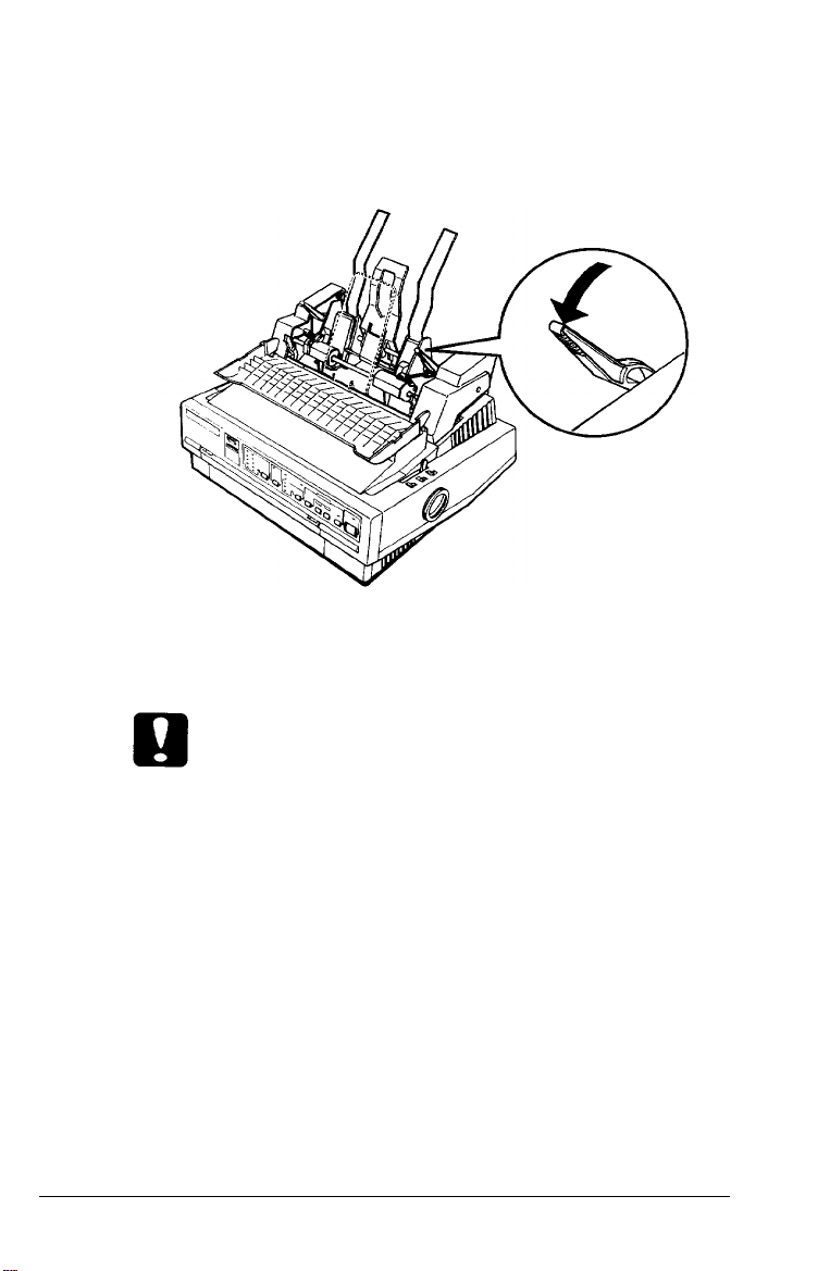
3. Pull the paper-set levers on each side of the cut-sheet feeder
all the way forward until the paper guides retract and lock
open to allow for paper loading.
4.
Take a stack of paper and fan it. Next, tap the side and
bottom of the paper on a flat surface to even up the stack.
Caution:
Do not use multi-part forms, carbon paper, or labels in the
cut-sheet feeder.
Insert up to
5.
150
sheets of paper or up to 30 air-mail or 25
plain bond envelopes.
6.
Adjust the position of the right paper guide so that it matches
your paper’s width. Make sure that the position of the
guide allows the paper to move freely up and down. Then
lock the right paper guide in place by pushing back on the
lock lever.
4-8 Using Printer Options
 Loading...