

Page 1
EPSON ActionPC and ActionTower 8600
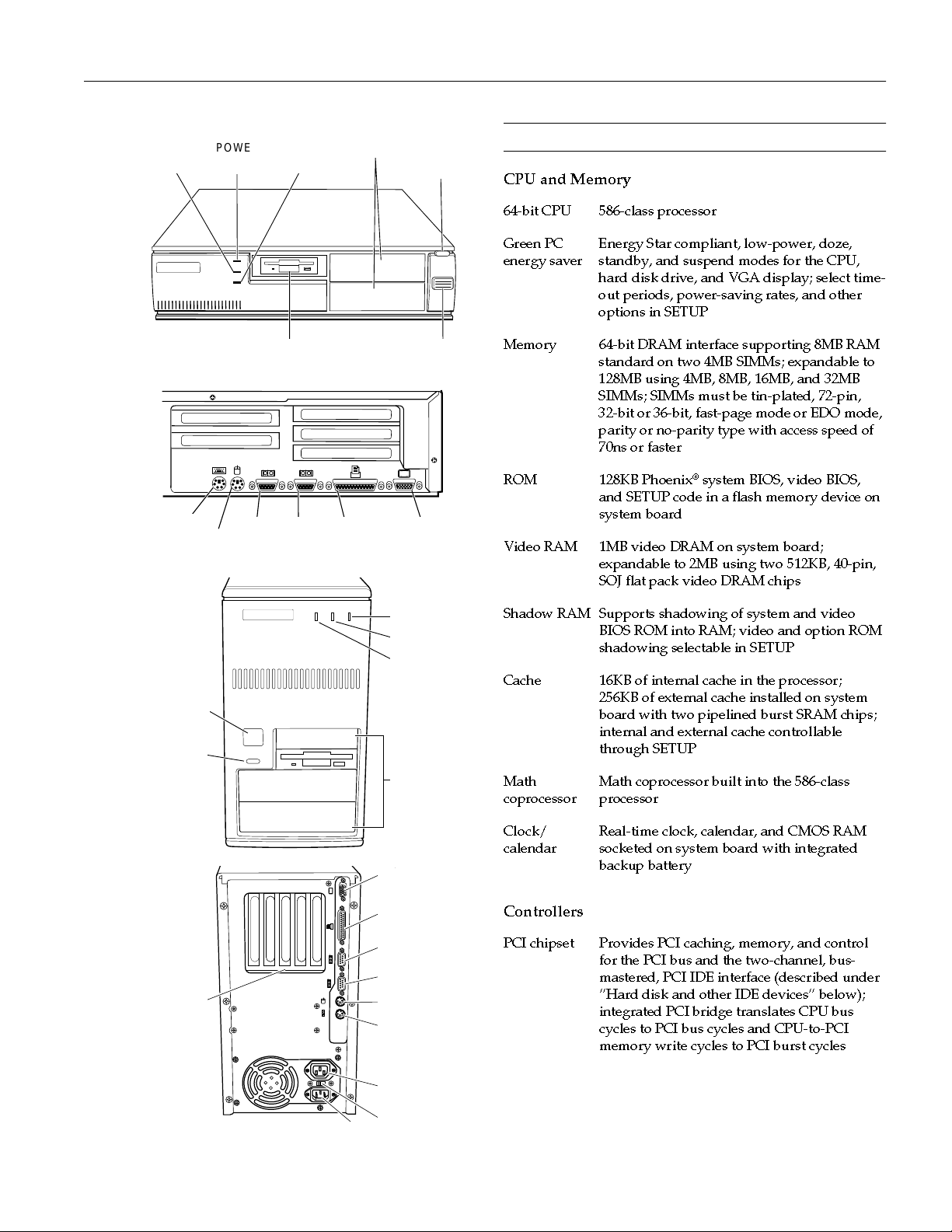
Slimline
comput e r
Tower
computer
SPEED
light
keyboard
POWER
button
RESET
button
POWER
light
mouse
hard disk
access light
(HDD)
diskette drive POWER
1
serial 2serial 1
2
drive bay s
printer
(parallel
port)
RESET
button
button
VGA
monitor
POWER light
SPEED light
hard disk
access light
(HDD)
drive bays
Computer Specifications
CPU and Memory
64-bit CPU 586-class process or
Green PC
energy saver
Memory 64-bit DRAM interface supporting 8MB RAM
ROM 128KB Phoenix
Video RAM 1MB video DRAM on system board;
Shadow RAM Supports shadowing of system and video
Cache 16KB of internal cache in the processor;
Math
coprocessor
Energy Star compliant, low-power, doze,
standby, and suspend modes for the CPU,
hard disk drive, and VGA display; select time-
out periods, power-saving rates, and other
options in SETUP
standard on two 4MB SIMMs; expandable to
128MB using 4MB, 8MB, 16MB, and 32MB
SIMMs; SIMMs must be tin-plated, 72-pin,
32-bit or 36-bit, fast-page mode or EDO mode,
parity or no-parity type with access spe ed of
70ns or faster
®
system BIOS, video BIOS,
and SETUP code in a flash memory device on
system board
expandable to 2MB using two 512KB, 40-pin,
SOJ flat pack video DRAM chips
BIOS ROM into RAM; video and option ROM
shadowing selectable in SETUP
256KB of external cache installed on system
board with two pipelined burst SRAM chips;
internal and external cache controllable
through SETUP
Math coprocessor built into the 586-class
processor
option
slots
power inlet
VGA monitor
printer
(par all el port )
serial 2
serial 1
mouse
keyboard
power outlet
voltage selector
switch
Clock/
calendar
Real-time clock, calendar, and CMOS RAM
socketed on system board with integrated
backup battery
Controllers
PCI chipset Provides PCI caching, memory, and control
for the PCI bus and the two-channel, bus-
mastered, PCI IDE interface (described under
Hard disk and other IDE devices below);
integrated PCI bridge translates CPU bus
cycles to PCI bus cycles and CPU-to-PCI
memory write cycles to PCI burst cycles
2/96
ActionPC and ActionTower 8600 - 1
Page 2
EPSON ActionPC and ActionTower 8600
champpig.fm5 (Left) 2/16/96 2:22pm
Video S3 Trio64V+ PCI VGA controller with
integrated 24-bit RAMDAC, 64-bit DRAM
interface; includes power-saving and
multimedia features; supports resolutions up
to 1280 × 1024 in 16 colors with 1MB of video
RAM, increasing to 256 colors with 2MB of
video RAM; True Color support at 640 × 480
resolution and Hi-Color support at 800 × 600
resolution
Diskette Controller on system board supports up to
two diskette drives, or one diskette/combo
diskette and one tape drive
Hard disk and
other IDE
devices
Two PCI, ATA-2 compatible, bus-mas tered
IDE interfaces on system board support up to
four IDE devices (two on each interface); IDE
CD-ROM drives cannot be connected to the
primary IDE interface or to the same interface
as IDE hard disk drives; BIOS provides hard
disk auto-sensing and enhanced IDE functions
Interfaces
Monitor Energy Star compliant video interface for
fixed or multifrequency monitor built into
system board; 15-pin, D-shell connector
Parallel One standard, multimode parallel interface
built into system board; supports 8-bit
unidirectional, 16-bit bidirectional EPP
(Enhanced Parallel Port) and ECP (Extended
Capability Port) modes; 25-pin, D-shell
connector; operation controllable by SETUP
program and jumpers
Serial Two high-speed RS-232C, programmable,
asynchronous interfaces built into system
board; 16C550 compatible; 9-pin, D-shell
connectors; operation controllable through
SETUP
Keyboard PS/2 compatible keyboard interface built into
system board; 6-pin, mini DIN connector
Mouse PS/2 compatible mouse interface built into
system board; 6-pin, mini DIN connector
Mass
Storage
Slimline
Internal bay:
One 3.5-inch wide, one-inch high drive
Externally accessible bays:
One 3.5-inch wide, one-inch high drive and
two 5.25-inch wide, half-height drives
Tower
Front internal bay:
One 3.5-inch wide, one-inch high drive
Rear internal bracket:
Two 3.5-inch wide, one-inch high drives or
one 3.5-inch wide, full-height drive
Externally accessible bays:
Two 3.5-inch wide, one-inch high drives and
two 5.25-inch wide, half-height drives
Diskette drive
types
3.5-inch diskette drive, 720KB or 1.44MB
storage capacity; 5.25 -inch diskette drive,
360KB or 1.2MB storage capacity; or a
combination 3.5-inch/5.25-inch diskette drive
Hard disk
drive types
5.25-inch or 3.5-inch form factor hard disk
drive(s), up to half-height size; maximum of
four drives
Other devices Half-height tape drives, CD-ROM drives,
optical drives, PCMCIA card readers, or other
devices; 5.25-inch, or 3.5-inch with mounting
frames
Keyboard
Detachable, two-pos ition height; 104 or 105
sculpted keys ; country-depe ndent main
typewriter keyboard; numeric/cursor control
keypad; four-key cursor control keypad;
12 function keys; 3 Windows 95 keys
Mouse
SETUP
Program
System
security
Virus
protection
Detachable, two-butt on, PS/2 compatible
Stored in ROM; accessible by pressing
Del
during boot
User and Supervisor level passwords
available for system boot or diskette access
Write protection feature for the hard disk
drive boot sector
Option slots Connector card with five I/O expansion slots;
three ISA compatible (8.33 MHz bus speed)
and two PCI bus-mastering slots (33 MHz bus
speed)
Speaker Internal
2 - ActionPC and ActionTower 8600
2/96
Page 3
EPSON ActionPC and ActionTower 8600
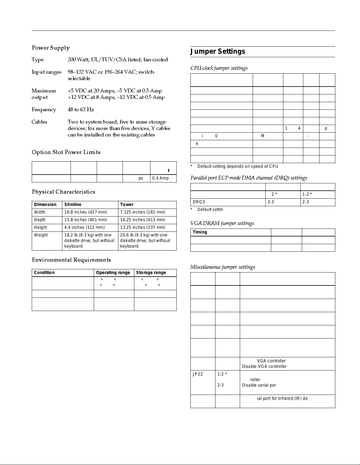
Power Supply
Type 200 Watt, UL/TUV/CSA listed, fan-cooled
Input ranges 98132 VAC or 196264 VAC; switch-
selectable
Maximum
output
+5 VDC at 20 Amps, 5 VDC at 0.5 Amp
+12 VDC at 8 Amps, 12 VDC at 0.5 Amp
Frequency 48 to 63 Hz
Cables Two to system board, five to mass storage
devices; for more than five devices, Y cables
can be installed on the existing cables
Option Slot Power Limits
Output voltage
(VDC) +5 Volts –5 Volts +12 Volts –12 Volts
For all slots 12 Amps 0.4 Amp 4.0 Amps 0.4 Amp
Physical Characteristics
Dimension Slimline Tower
Width 16.8 inches (427 mm) 7.125 inches (181 mm)
Depth 15.8 inches (401 m m) 16.25 inches (413 mm)
Height 4.4 inches (112 mm) 13.25 inches (337 mm)
Weight 18.2 lb (8.3 kg) with one
diskette drive, but without
keyboard
20.6 lb (9.3 kg) with one
diskette drive, but without
keyboard
Environmental Requirements
Condition Operating range Storage range
Temperature 41° to 90° F
(5° to 32° C)
Humidity (non-condensing) 20% to 90% 10% to 90%
Altitude –330 to 9,900 ft
(–100 to 3,000 m)
–4° to 140° F
(–20° to 60° C)
–330 to 39,600 ft
(–100 to 12,000 m)
Jumper S et t ings
CPU clock jumper settings
CPU type *
Cyrix 6x86-P120+ (100 MHz) 50 MHz Open 1-2 Open
Cyrix 6x86-P150+ (120 MHz) 60 MHz 3-4 1-2 Open
Cyrix 6x86-P166+ (133 MHz) 66 MHz 1-2, 3-4 1-2 Open
Pentium 75 MHz 50 MHz Open Open Open
Pentium 90 MHz 60 MHz 3-4 Open Open
Pentium 100 MHz 66 MHz 1-2, 3-4 Open Open
Pentium 120 MHz 60 MHz 3-4 1-2 Open
Pentium 133 MHz 66 MHz 1-2, 3-4 1-2 Open
Pentium 150 MHz 60 MHz 3-4 1-2 1-2
Pentium 166 MHz 66 MHz 1-2, 3-4 1-2 1-2
* Default setting depends on speed of CPU
Parallel port ECP mode DMA channel (DRQ) settings
DMA channel JP23 JP24
DRQ1 1-2 * 1-2 *
DRQ3 2-3 2-3
* Default setting
VGA DRAM jumper settings
Timing mode JP3 J P2 0
Fast page mode 1-2 * 1-2 *
EDO mode 2-3 2-3
* Default setting
Miscellaneous jumper settings
Jumper
number
JP1 1-2
JP4 2-3 *
JP6 2-3 *
JP16 1-2
JP18 5- 6 *
JP21 1- 2 *
JP22 1- 2 *
J20 5- 6, 7-8 *
* Default setting
Jumper
setting Function
Open *
1-2
1-2
Open *
3-4
1-2
2-3
2-3
Ope n
External
clock speed JP12 JP17 JP29
Clear th e CMOS SETUP values
Normal CMOS op erati on
1MB video DRAM
2MB video DRAM
System clock PCICLK/4
System clock PCICLK/3
Write-b ac k cac he
Write-through cache
+3.3 V CPU voltage
+3.358 V – 3.36 V (VR) CPU voltage
+3.525 V – 3.528 V (VRE) CPU voltage
Enable VGA controller
Disable VGA controller
Enable serial ports and diskette drive
controller
Disable serial ports and diskette drive
controller
Use serial port for infrared (IR) device
Use IR module connector for IR device
2/96
ActionPC and ActionTower 8600 - 3
Page 4

EPSON ActionPC and ActionTower 8600
Syste m Board Co mponents
The diagram below illustrates the components on the system board.
champpig.fm5 (Left) 2/16/96 2:22pm
video memory
chips and sockets
SVGA feature
connector
video controller
speak er
SIMM sockets
core logic chipset
VGA
port
J9
JP21
parallel
device port
U10
U22
JP3
JP4
U9 U8 U7
JP6
JP20
U33
U34
serial 2
port
U20
JP12
JP13
U31
U26
JP1
serial 1
port
S1
U3 U2
U29
U17
U28
mouse
port
JP23
JP22
JP24
JP8
JP9
JP10
JP11
keyboard
port
power supply
connector
diskette drive connector
primary IDE connector
secondary IDE connector
tag RAM
external cache
4 - ActionPC and ActionTower 8600
IR module
connector
J20
J21
VRM
connector
processor
2/96
U35
JP16
JP17
JP15
JP18
JP29
voltage regulator
Page 5

EPSON ActionPC and ActionTower 8600
System board components
Connector Function
PS1 Power connector
J14 Primary IDE connector
J1 PS/2 keyboard connector
J13 Diskette drive connector
J15 Secondary IDE connector
J22 HDD LED connector
J3 PS/2 mou se co nne ct o r
J5 Serial 1 port connector
J6 Serial 2 port connector
J21 Pins 2-3: Turbo LED connector
J7 Printer (parallel) port connector
J9 SVGA feature connector
J8 15-pin DIN type VGA connector
S1 Riser card slot; default settings of PCI AD Select are
U28, U35 External cache SRAM chips
U2 AMIKEY-2 keyboard controller
U27 Cache tag RAM chip
U3 Phoenix system and video BIOS chip
U31 Processor (CPU)
U6 Dallas DS 12887 real-time clock chip
U17 SMC FDC 37C665 parallel port super I /O disk et te
U8, U10 Soldered standard video RAM
U20, U29,
U33, U34
U22 S3 Trio64V+ VGA controller
U7, U9 Video DRAM expansion sockets
Pins 9-10: Hardware reset connector
Pins 11-13: Power LED connector
Pins 17-20: Sp eaker connector
AD12 and AD13
controller
PCI chipset
SIMM Installation
The computer comes with 16MB of RAM standard on two
8MB SIMMs. You can increase the memory up to 128MB
using 4MB, 8MB, 16MB, or 32MB SIMMs. The SIMMs mus t be
tin-plated, 72-pin, single- or double-sided, fast-page mode or
EDO mode, parity or no-parity type with an access speed of
70ns or faster. Be sure all the SIMMs operate at the same
speed.
The table below lists all the possible SIMM configurations; do
not install SIMMs in any other configuration.
SIMM configurations
Bank 0 Bank 1
Total memorySIM1 SIM2 SIM3 SIM4
4MB 4MB — — 8MB
——4MB4MB8MB
4MB 4MB 4MB 4MB 16MB
4MB 4MB 8MB 8MB 24MB
4MB 4MB 16MB 16MB 40MB
4MB 4MB 32MB 32MB 72MB
8MB 8MB — — 16MB
— — 8MB 8MB 16MB
8MB 8MB 4MB 4MB 24MB
8MB 8MB 8MB 8MB 32MB
8MB 8MB 16MB 16MB 48MB
8MB 8MB 32MB 32MB 80MB
16MB 16MB — — 32MB
— — 16MB 16MB 32MB
16MB 16MB 4MB 4MB 40MB
16MB 16MB 8MB 8MB 48MB
16MB 16MB 16MB 16MB 64MB
32MB 32MB — — 64MB
— — 32MB 32MB 64MB
32MB 32MB 4MB 4MB 72MB
32MB 32MB 8MB 8MB 80MB
32MB 32MB 16MB 16MB 96MB
32MB 32MB 32MB 32MB 128MB
2/96
ActionPC and ActionTower 8600 - 5
Page 6

EPSON ActionPC and ActionTower 8600
champpig.fm5 (Left) 2/16/96 2:22pm
System Memory Map
Address range Function
FE0000h-FFFFFFh 128KB duplication of ROM BIOS stored at
0E0000h-0FFFFFh
100000h-FDFFFFh System extended memory (128MB maximum)
0E0000h-0FFFFFh 128KB ROM BIOS
0C8000h-0DFFFFh Adapter ROM BIOS
0C0000h-0C7FFFh Video ROM BIOS
0A0000h-0BFFFFh 128KB video memory
000000h-09 FFFFh 640KB base memor y
Video M emory
The computer comes with 1MB of video memory. You can
increase the video memory to 2MB by installing two 512KB,
40-pin, SOJ flat pack video DRAM chips.
Memo r y
Resol ut ion
ment s Color
640 × 480 1MB 256 60/72/75 8 bits/pi xe l
1MB 32 K/64 K 60 /72 /75 16 bits/pixel
2MB 16.8M
(True
Color)
800 × 600 1MB 256 56/60/72/75 8 bits /pi xe l
1MB 32 K/64 K 60 /72 /75 16 bits/pixel
2MB 16.8M
(True
Color)
1024 × 768 1MB 256 43.5/60/70/75 8 bits /pi xe l*
2MB 64 K 43 .5/6 0/70/75 16 bits/pixel**
1280 × 1024 1MB 16 43.5/60/72/75 4 bit pla nes *
2MB 25 6 43.5/6 0/7 2/75 8 bits/ pi xe l**
1600 × 1200 2MB 256 43.5 8 bits/pi xe l* *
* Non-interlaced and interlaced
** Interlaced
require-
Refresh
rates (Hz) Remarks
60/72/75 24 bits/pixel
60/72/75 24 bits/pixel
Processor Up grades
You can upgrade your processor with a faster one to improve
system performance. If you upgrade the processor, you may
want to lay the computer on its side to make the process
easier. If you are upgrading to a 100 MHz processor, make
sure you use a standard 3.3 V processor.
Hard Disk Drive Types
The computer comes with a hard disk auto-sensing feature.
To use it, select one of the drives you have installed from the
Fixed Disk Setup screen. On the scree n that appears for that
drive, press
Enter
to select the
Autotype Fixed Disk
option. The system dete cts the type of hard disk drive, fills in
the drives parameters, and sets the remaining options on the
screen.
Hard Disk Drive Inform at ion
The IDE hard disk drives listed in the tables below are
qualified for use in your computer.
IDE hard disk drive parameters
®
Conner
Parameters
Formatted
cap a ci ty (MB)
Size,width ×
height (in)
Weight (lb) 1.25 1.25 1.2 5 1. 25 1.25 1.25 1.5 . 75 1.3
Cylinders 3640 3640 3640 3924 3678 3678 4708 5414 3164
Disks 32213 2322
Heads 64326 4644
Sectors per
track
Rotational
speed (RPM)
Bu ffer siz e
(KB)
Average seek
tim e (ms)
Encoding
method
Po w e r
dissipat ion
(seek)
Logical parameters
Cylinders 2477 1651 1238 1048 3144 2096 3150 2485 1223
Heads 16 16 16 16 16 16 16 16 16
Precomp
zone
Landing
zone
Sectors 6363636363 63636363
CFS12 75A
CFS850A
CFS635A
CFS541A
1275 850 635 540 1620 1080 1625 1282 631
4 × 14 × 14 × 14 × 14 × 14 × 14 × 14 ×
77 -
78 -
78 -
143
143
3600 3600 3600 3600 4500 4500 5400 5400 3811
64 64 64 64 256 256 256 12 8 120
14 14 14 14 11 11 10.5 10 .5 14
RLL
RLL
1,7
1,7
3.5 W3.5 W3.5 W3.9 W4.0W4.0W 8.41W6.4W 5 .2
00000 0000
2477 1651 1238 1048 3144 2096 4726 5376 3164
144
RLL
1,7
90 170
RLL
1,7
®
NEC
D3747
D3745
76 142
PRML PRMLRLL
1,7
Seagate
ST31640A
.75
RLL
1,7
ST51270A
®
4 × 1
66 115
RLL
1,7
W
ST3630A
6 - ActionPC and ActionTower 8600
2/96
Page 7

IDE hard disk drive settings
Model number Single drive M aster drive Slave drive
Conner CFS1275A C/D jumpered C/D jumpered No jumpers
Conner CFS850A C/D jumper ed C/D jumpered No jumpers
Conner CFS635A C/D jumper ed C/D jumpered No jumpers
Conner CFS541A C/D jumper ed C/D jumpered No jumpers
NE C D374 7 SW1 on,
SW2–SW4 off
NE C D374 5 SW1 on,
SW2–SW4 off
Seagate ST31640A No jum per s 3-4 jumpered 1 -2 jumpered
Seagate ST51270A No jum per s 3-4 jumpered 1 -2 jumpered
Seagate ST3630A No jumper s No jumpers 7-8 jum pered
SW1 on,
SW2–SW4 off
SW1 on,
SW2–SW4 off
SW1–SW4 off
SW1–SW4 off
DMA Assignme nts
Level Assigned device
DMA0 Reserved
DMA1 Available
DMA2 Diskette drive controller
DMA3 Available
DMA4
DMA5 Spare
DMA6 Spare
DMA7 Spare
Cascade from DMA1
Hardware Interrupts
IRQ no. Func tion
IRQ0 Internal timer
IRQ1 Keyboard
IRQ2 Cascade to IRQ9
IRQ3 Serial port 2
IRQ4 Serial port 1
IRQ5 LPT2
IRQ6 Diskette drive controller
IRQ7 Parallel port 1
IRQ8 Real-time clock
IRQ9 Cascaded from IRQ2
IRQ10 Available
IRQ11 Available
IRQ12 PS/2 mouse
IRQ13 Math coprocess or
IRQ14 Primary IDE controller
IRQ15 Secondary IDE controller
EPSON ActionPC and ActionTower 8600
System I/O Address Map
Hex address Assigned device
000 - 01F DMA controller 1, 8237
020 - 03F Interrupt controller 1, 8259
022 - 024 Reserved
040 - 05F Timer, 8254
060 - 06F Keyboard controller, 8242PE
070 - 07F Real-time clock NMI (non-maskable interrupt)
080 - 09F DMA page register, 74LS612
0A0 - 0BF Interrupt controller 2, 8259
0C0 - 0DF DMA controller 2, 8237
0F0 Clear math copro ces so r
0F1 Reset math coprocessor
0F8 - 0FF Math coprocessor
1F0 - 1F8 Primary hard disk interface
1E0 - 1E7 Secondary hard disk interface
200 - 207 Game I/O
278 - 27F Parallel printer port 2
2B0 - 2DF Alternate enhanced graphics adapter
2E1 GPIB (adapter 0)
2E2, 2E3 D ata acquisition (adapter 0)
2F8 - 2FF Serial port 2
300 - 31F Prototype card
360 - 363 Available
368 - 36B Available
378 - 37A Parallel printer port 1
380 - 38F Available
390 - 393 Available
3A0 - 3AF Available
3B0 - 3BF Available
3C0 - 3CF VGA adapter
3D0 - 3DF VGA adapter
3F0 - 3F5 Diskette drive controller
3F8 - 3FF Serial port 1
6E2, 6E3 Available
790 - 793 Available
AE2, AE3 Available
B90, B93 Available
EE2, EE3 Available
1390 - 1393 Available
22E1 Available
2390 - 2393 Available
42E1 Available
63E1 Available
82E1 Available
A2E1 Available
C2E1 Available
E2E1 Available
2/96
ActionPC and ActionTower 8600 - 7
Page 8
EPSON ActionPC and ActionTower 8600
champpig.fm5 (Left) 2/16/96 2:22pm
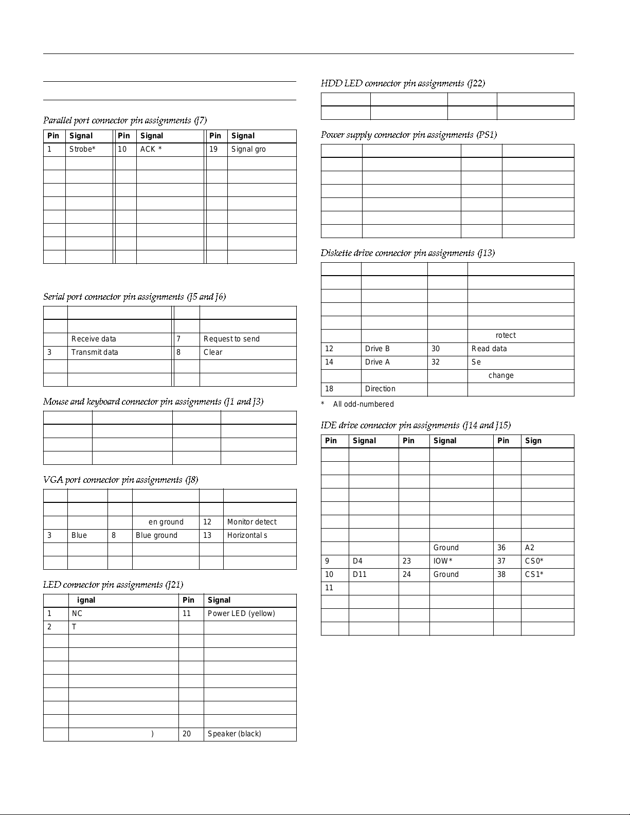
Connector Pin Assignments
Parallel port connector pin assignments (J7)
Pin Signal Pin Signal Pin Signal
1 Strobe* 10 ACK * 19 Sign al grou nd
2 Data 0 11 Busy 20 Signal gr ou nd
3 Data 1 12 PE 21 Signal gr ou nd
4 Data 2 13 Select 22 Signal grou nd
5 Data 3 14 AFD * 23 S ign al ground
6 Data 4 15 Error * 24 Sign al gr ou nd
7 Data 5 16 Init * 25 Signal gr ou nd
8 Data 6 17 Selectin * — —
9 Data 7 18 Signal ground — —
* Active LOW logic
Serial port connector pin assignments (J5 and J6)
Pin Signal Pin Signal
1 Data carrier detect 6 Data set ready
2 Receive data 7 Request to send
3 Transmit data 8 Clear to send
4 Data terminal ready 9 Ring indicator
5 Ground — —
Mouse and keyboard connector pin assignments (J1 and J3)
Pin Signal Pin Signal
1 Data 4 VCC
2 NC 5 Clock
3 Ground 6 NC
VGA port connector pin assignments (J8)
Pin Signal Pin Signal Pin Signal
1 Red 6 Red ground 11 NC
2 Green 7 Green ground 12 Monitor detect
3 Blue 8 Blue grou nd 13 Horizontal sync
4 NC 9 NC 14 Vertical sync
5 Ground 10 Ground 15 NC
LED connector pin assignments (J21)
Pin Signal Pin Signal
1 NC 11 Power LED (yellow)
2 Turbo LED (yellow) 12 NC
3 Turbo LED (white) 13 Power LED (white)
4 NC 14 NC
5 NC 15 NC
6 NC 16 NC
7 NC 17 Speaker (red)
8 NC 18 NC
9 Hardware reset (white) 19 NC
10 Hardware reset (yellow) 20 Speaker (black)
HDD LED connector pin assignments (J22)
Pin Signal Pin Signal
1Red 2White
Power supply connector pin assignments (PS1)
Pin Signal Pin Signal
1 Power good 7 Ground
2 +5 VDC 8 Ground
3 +12 VDC 9 -5 VDC
4 -12 VDC 10 + 5 VDC
5 Ground 11 +5 VDC
6 Ground 12 +5 VDC
Diskette drive connector pin assignments (J13)
Pin* Signal Pin* Signal
2NC 20Step
4 NC 22 Write data
6 NC 24 Write enable
8 Index 26 Track 0
10 Motor A 28 Write protect
12 Drive B 30 Read data
14 Drive A 32 Select header 0
16 Motor B 34 Disk change
18 Direction
* All odd-numbered pins are grounds
IDE drive connector pin assignments (J14 and J15)
Pin Signal Pin Signal Pin Signal
1 RESET* 15 D1 29 NC
2 Ground 16 D14 30 Ground
3D7 17D0 31IRQ14
4 D8 18 D15 32 IOCS16*
5 D6 19 Ground 33 A1
6D9 20NC 34NC
7D5 21NC 35A0
8 D10 22 Ground 36 A2
9 D4 23 IOW* 37 CS0*
10 D11 24 Ground 38 CS1*
11 D3 25 IOR* 39 Active*
12 D12 26 Ground 40 Ground
13 D2 27 IOCHRDY*
14 D13 28 BALE
*Acti ve low logic
8 - ActionPC and ActionTower 8600
2/96
Page 9

EPSON ActionPC and ActionTower 8600
Option card riser board connector pin assignments
Pin Signal Pin Signal Pin Signal Pin Signal
A1 +12 VDC A31 SA3 B1 +12 VDC B31 BALE
A2 Ground A32 SA2 B2 +5 VDC B32 +5 VDC
A3 Ground A33 SA1 B3 Ground B33 OSC
A4 IOCHCK* A34 SA0 B4 Ground B34 Ground
A5 SD7 A35 Ground B5 RESETDRV B35 Ground
A6 SD6 A36 Ground B6 +5 VDC B36 +5 VDC
A7 SD5 A37 +5 VDC B7 IRQ9 B37 +5 VDC
A8 SD4 A38 SBHE* B8 5 VDC B38 MEMCS16*
A9 SD3 A39 LA23 B9 DRQ2 B39 IOCS16*
A10 SD2 A40 LA22 B10 12 VDC B40 IRQ10
A11 SD1 A41 LA21 B11 OWS * B41 IRQ11
A12 SD0 A42 LA20 B12 +12 VDC B42 IRQ12
A13 IOCHRDY A43 LA19 B13 Ground B43 IRQ15
A14 AEN A44 LA18 B14 SMEMW* B44 IRQ14
A15 SA19 A45 LA17 B15 SMEMR* B45 DACK0*
A16 SA18 A46 MEMR* B16 IOW* B46 DRQ0
A17 SA17 A47 MEMW* B17 IOR* B47 DACK5*
A18 SA16 A48 SD8 B18 DACK3* B48 DRQ5
A19 SA15 A49 SD9 B19 DRQ3 B49 DACK6*
A20 SA14 A50 SD10 B20 DACK1* B50 DRQ6
A21 SA13 A51 SD11 B21 DRQ1 B51 DACK7*
A22 SA12 A52 SD12 B22 REFRESH* B52 DRQ7
A23 SA11 A53 SD13 B23 SYSCLK B53 +5 VDC
A24 SA10 A54 SD14 B24 IRQ7 B54 MASTER*
A25 SA9 A55 SD15 B25 IRQ6 B55 Ground
A26 SA8 A56 Ground B26 IRQ5 B56 Ground
A27 SA7 A57 Ground B27 IRQ4 B57 Ground
A28 SA6 A58 Ground B28 IRQ3 B58 +5 VDC
A29 SA5 A59 +5 VDC B29 DACK2* B59 +5 VDC
A30 SA4 A60 +5 VDC B30 TC B6 0 +5 VDC
* Active low logic
ISA option slot connector pin assignments
Pin Signal Pin Signal Pin Signal Pin Signal
A1 IOCHCK* A26 SA5 B2 0 SYSCLK C14 SD11
A2 SD7 A27 SA4 B21 IRQ7 C15 SD12
A3 SD6 A28 SA3 B22 IRQ6 C16 SD13
A4 SD5 A29 SA2 B23 IRQ5 C17 SD14
A5 SD4 A30 SA1 B24 IRQ4 C18 SD15
A6 SD3 A31 SA0 B25 IRQ3 D1 Memcs16*
A7 SD2 B1 Ground B26 DACK2* D2 IOCS16*
A8 SD1 B2 RESETDRV B27 T/C D3 IRQ10
A9 SD0 B3 +5 VDC B28 BALE D4 IRQ11
A10 IORDY B4 IRQ9 B29 +5 VDC D5 IRQ12
A11 AEN B5 5 VDC B30 OSC D6 IRQ15
A12 SA19 B 6 D R Q2 B31 Groun d D 7 IRQ 14
A13 SA18 B7 12 VDC C1 SBHE* D8 DACK0*
A14 SA17 B8 OWS* C2 SA23 D9 DREQ0
A15 SA16 B9 +12 VDC C3 SA22 D10 DACK5*
A16 SA15 B10 Ground C4 SA21 D11 DREQ5
A17 SA14 B11 SMEMW* C5 SA20 D12 DACK6*
A18 SA13 B12 SMEMR* C6 SA19 D13 DRQ6
A19 SA12 B13 IOW* C7 SA18 D14 DACK7*
A20 SA11 B14 IOR* C8 SA17 D15 DREQ7
A21 SA10 B15 DACK3* C9 MEMR* D16 +5 VDC
A22 SA9 B16 DREQ3 C10 MEMW* D17 MASTER*
A23 SA8 B17 DACK1* C11 SD8 D18 Ground
A24 SA7 B18 DREQ1 C12 SD9
A25 SA6 B19 REF* C13 SD10
* Active low logic
SIMM socket connector pin assignments
Pin Signal Pin Signal Pin Signal Pin Signal
1 Ground 19 NC 37 DP1 55 DQ11
2 DQ0 20 DQ4 38 DP3 56 DQ27
3DQ1621DQ2039Ground57DQ12
4 DQ1 22DQ5 40CAS0* 58DQ28
5DQ1723DQ2141CAS2*59VCC
6 DQ2 24DQ6 42CAS3* 60DQ29
7DQ1825DQ2243CAS1*61DQ13
8 DQ3 26DQ7 44RAS0* 62DQ30
9DQ1927DQ2345RAS1*63DQ14
10VCC 28A7 46A10A 64DQ31
11 NC 29 NC 47 WE* 65 DQ15
12 A0 30 VCC 48 A10B 66 NC
13 A1 31 A8 49 DQ8 67 PD1
14 A2 32 A9 50 DQ24 68 PD2
15 A3 33 RAS3* 51 DQ9 69 PD3
16 A4 34 RAS2* 52 DQ25 70 PD4
17 A5 35 DP2 53 DQ10 71 NC
18 A6 36 DP0 54 DQ26 72 Ground
* Activ e low lo gic
2/96
ActionPC and ActionTower 8600 - 9
Page 10
EPSON ActionPC and ActionTower 8600
champpig.fm5 (Left) 2/16/96 2:22pm
Tested Op erating E nvironments
Although your system will run most software applications,
the following operating environments have been tested for
compatibility with your syste m.
Microsoft® MS-DOS 3.3 and later
Novell NetWare* 3.12 and 4.1
Novell Personal NetWare
IBM® OS/2; including version 3.0 (Warp)
SCO®UNIX
SCO Open Desktop
Microsoft Windows 3.1 and later
Microsoft Windows 95
Microsoft Windows for WorkGroups
Microsoft Windows NT; including version 3.5
* Certified as workstation and file server in certain configurations
As new environments become available, these also will be
teste d.
Installation/Support Tips
Installing Diskette Drives
Booting Sequence
If you cannot boot the computer from the hard disk, make
sure the booting sequence in SETUP is set to
Then boot the computer from a system diskette in drive A.
A: then C:
.
Password
If you forget your password, you must discharge your CMOS
memory as follows:
1. Turn off the computer and remove the cover.
2. Disable the password by setting jumper JP1 on the syste m
board to position 1-2.
3. Turn the computer on, leave it on for a few seconds, then
turn it off again.
4. Set jumper JP1 back to the Open position (remove jumper)
to enable the password function.
5. Run SETUP to enter a new password, if desired.
Information Reference List
Engineering Change Notices
Make sure that the drive type has be en correctly s electe d in
❏
the SETUP program.
Make sure jumper JP22 is set to position 1-2 to enable the
❏
diskette drive controller. Also make sure that the Diskette
Controller option is enabled in the BIOS SETUP program.
Installing Hard Disk Drives
If you are installing a drive that cannot use the embedded
❏
IDE interface (such as an ESDI drive), it is recommended
that you use a 16-bit, AT-type hard disk controller and a
PCI hard disk controller for higher performance. If you
install a non-IDE hard disk drive and controller card, you
must disable the built-in IDE hard disk drive interface (use
the Local Bus IDE Adapter option in the BIOS SETUP
program). Also, remo ve the hard disk drive ribbon
connector from the system board.
When installing an IDE hard disk drive, use the auto-
❏
sensing feature in SETUP to select the correct type for the
drive. If the auto-s ensing feature do es not p roduce a ma tch
for the drive, you can define your own drive type by
selecting
parameters .
as the type and entering the drive's
User
Installing Option Cards
None.
Technical Information Bulletins
None.
Product Support Bulletins
None.
Related Documentation
TM- EPSON ActionPC 8600, ActionTower 8600
Service Manual
PL- EPSON ActionPC 8600, ActionTower 8600
Parts Price List
400537700 EPSON ActionPC 8600, ActionTower 8600
Users Guide
If you are installing a video adapter card, make sure you
disable the built-in VGA controller by setting jumper JP21
to 2-3.
10 - ActionPC and ActionTower 8600
2/96
 Loading...