

Page 1
EPSON ActionNote 800 Series
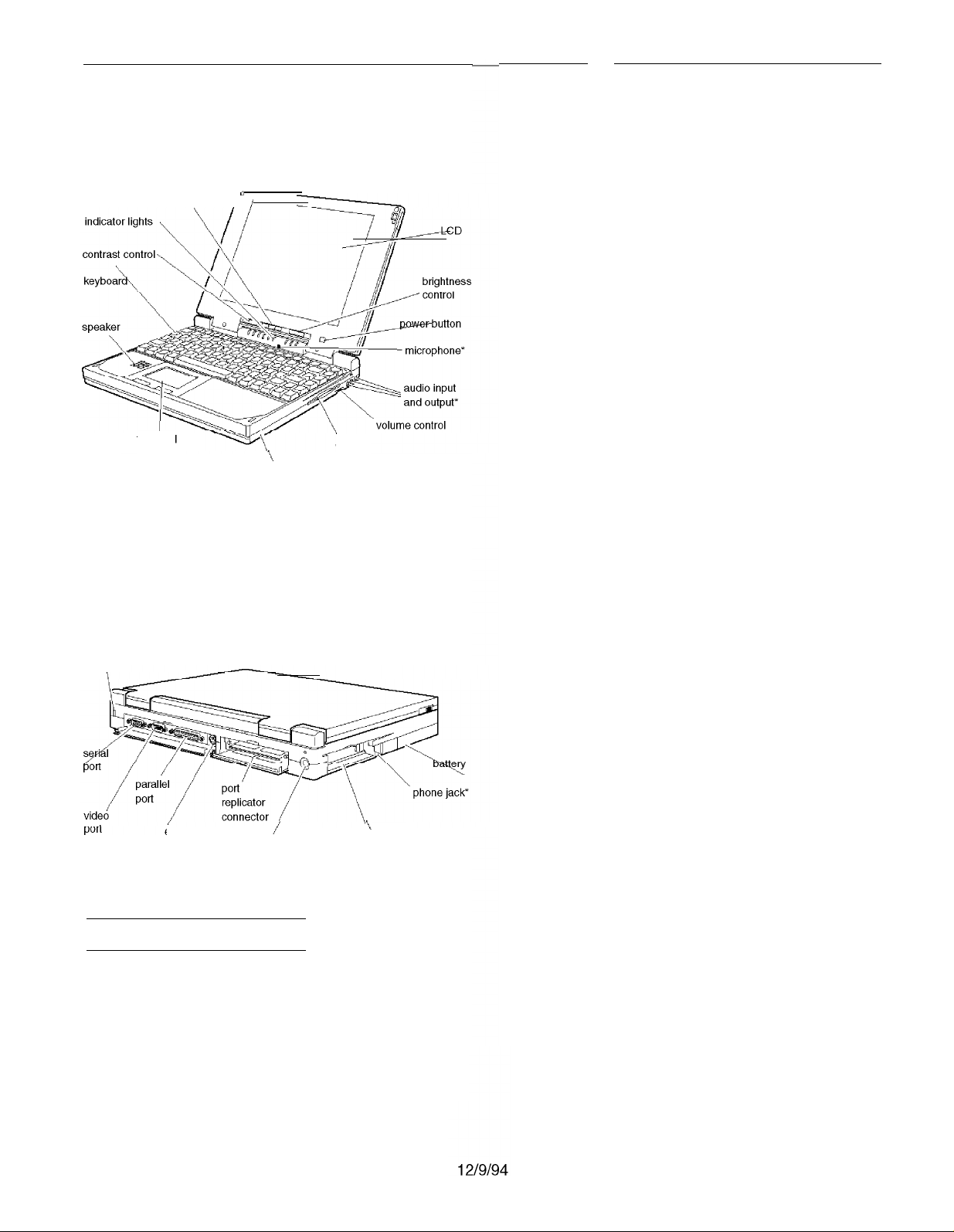
Front View
suspend/resume button
trackpad
* These parts function only with the optional audio card installed
0
/
\
hard disk drive
compartment
diskette
drive
Rear Panel and Left Side
security
Memory
ROM
Video RAM
Cache
Clock/
calendar
Controllers
Video
4MB RAM soldered on the system board;
configuration may include additional
memory module; expandable up to 24MB
using a 4,8,16, or 20MB memory
expansion module
128KB Flash ROM device containing the
system and video BIOS and Setup
program code
512KB DRAM supports resolutions up to
640 x 480 in 256 colors on the color LCD
and up to 1024 x 768 in 16 colors or
800 x 600 in 256 colors on external monitor
8KB internal; supports 256KB of external
cache on a CPU daughterboard; selectable
through Setup
Real-time clock, calendar, and CMOS
RAM; backed up by internal battery
Chips and Technology® 65535 video
controller; 32-bit local bus interface to the
microprocessor; supports enhanced video
modes on an external monitor; supports
resolutions from 640 x 480 in 256 colors on
the color LCD and up to 1024 x 768 in 16
colors on an external monitor; automatic
external monitor detection; simultaneous
display with LCD screen using Fn F10
command or software
external
keyboard or
mouse pod
*Available only with the optional internal fax/modem installed
/
DC-in pod
\
PC card
slots
Notebook Specifications
CPU and Memory
CPU
System speed Fast speed and slow speed (8 MHz)
Upgradable 486 microprocessor installed
in a PGA socket; includes 8KB of internal
cache in write-back mode and integrated
math coprocessor
available; speed selection through Setup
Diskette drive
Hard disk
PCMCIA
Interfaces
External VGA
Parallel
Built-in super I/O controller for one
internal 3.5-inch diskette drive; supports
720KB and 1.44MB formats
Built-in super I/O controller has interface
to one 2.5-inch, IDE internal hard disk
drive; automatically recognizes and
configures drives up to 19 mm high that
support the IDE interface
Built-in Vadem® VG-468 controller for two
stacked slots; supports two Type I or II
cards, or one Type III; PCMCIA version
2.01 and JEIDA 4.1 compatible; supports
low power and suspend modes; supports
hot insertion (including ExCA standards);
register compatible with Intel 82365SL
Auto-sensing, 15-pin, D-sub, female
connector for analog monitor
Centronics® compatible; 25-pin, D-sub,
female connector; standard S-bit parallel;
supports standard (AT compatible) and
bidirectional (PS/2 compatible) modes
AN800-1
Page 2
EPSON ActionNote 800 Series
Serial
RS-232C, programmable, asynchronous,
9-pin, D-sub male connector
External
keyboard/
mouse
Phone jack
Auto-sensing, 6-pin mini-DIN connector
for a PSI 2-type external keyboard,
keypad, or pointing device
Standard RJ-11 connector with optional
internal fax/ modem installed
Speaker Internal; automatically disabled when
optional audio card is installed and
Line-out is used
Audio input
and output
Connectors for microphone, Line-in, and
Line-out when optional audio card is
installed
Port replicator
Keyboard
Connector for ActionPort™ replicator
85 keys; 101-key keyboard compatible;
embedded numeric keypad; Fn key for hot
key commands
Trackpad
Fax/Modem
Built-in pointing device with two buttons
Optional internal 14.4 baud send/ receive
fax/ modem
Volume
Control
Knob adjusts sound of internal speaker or
audio card (if installed)
Software
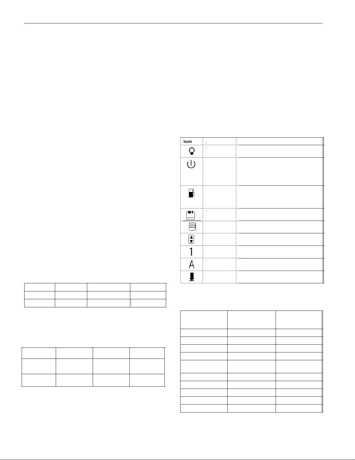
LED Panel
Name
Power
Suspend
Charge
Diskette drive
Hard disk drive
Latest versions of MS-DOS® and Microsoft
Windows™Borland® SideKick® for
Windows; ClarisWorks® for Windows;
trial versions of CompuServe® WinCIM,®
America Online,® and OAG FlightDisk;®
drivers and utilities for PCMCIA card
slots, video system, and trackpad; on-line
version of User’s Guide, Windows manual,
and other manuals; power management
utilities; all installed on the hard disk
drive; refer to Software Support Card for
details on EPSON’s support policy
Meaning
Computer is on
Green -Standby mode; press any key to
return to full power
Flashing green -Suspend mode; press
Suspend/Resume button to return to full
power
Orange -battery is charging normally
Green -battery is fully charged
Flashing orange -battery is not installed
correctly or is damaged
Computer is accessing the diskette drive
Computer is accessing the hard disk drive
Mass Storage
Hard disk drive
Capacity 335MB
Heads 16
Cylinders 682
Diskette drive Internal 3.5-inch diskette drive; 720KB or
One removable internal IDE hard disk
drive, 2.5-inch form factor; maximum
height 19 mm; Setup automatically
recognizes and configures drives that
support the IDE interface; parameters for
the Toshiba MK1824FCV are as follows:
Sectors 63
WP Com
Landing Zone
0
682
1.44MB format; supports lower power
consumption
LCD Screen
Screen type
(all backlit)
Resolutions
and colors
Diagonal
measurement
640 x 480,64
gray shades
9.4 inches
Setup Program Stored in ROM; accessible by pressing F8
at system startup; includes power
management utilities
Passive color Active colorMonochrome
640 x 480
256 colors
10.3 inches 10.4 inches
640 x 480
256 colors
PCMCIA
Num Lock
Caps Lock
Scroll Lock
Power Sources
AC adapters
Specification
AC connection
DC cable
Input voltage
Input frequency
Output voltage
Length
Width
Height
Weight
Computer is accessing a PC card
Num Lock is on, which activates the
embedded numeric keypad
Caps Lock is on
Scroll Lock is on
Lightweight
AC adapter
(A882051)
2 folding connectors
6 ft (2 meters)
100 VAC to 240 VAC
50/60 Hz
19 VDC, 1.23 Amp
maximum
3.4” (86 mm) 3.4” (86 mm)
2.2” (56 mm) 2.2” (56 mm)
1.1” (28 mm) 1.1” (28 mm)
7.8 oz (220 g) 9 oz (255 g)
International
AC adapter
(A882101)
6 ft (2 meter) cable
6 ft (2 meters)
100 VAC to 240 VAC
50/60 Hz
19 VDC, 1.5 Amp
maximum
AN800-2
12/9/94
Page 3
EPSON ActionNote 800 Series
Battery Rechargeable 12 Volt NiMH battery;
current regulation by thermistor
Caution
Use only the adapters and replacement batteries designed
for use with the ActionNote 800 series (lightweight AC
adapter A882051, international AC adapter A882101, auto
adapter A882241, and battery A882291).
Environmental Requirements
Condition
Temperature
Humidity
(non-condensing)
Altitude
Acoustical noise
Caution
When traveling by airplane, take the computer into the
passenger compartment to prevent it from being stored in
an unpressurized storage compartment.
Operating
42° to 95° F
(5° to 35° C)
30% to 90%
--200 to 12,000 ft
(--67 to 4,000 m)
35 dB @ 1 meter
(maximum)
Non-operating
-4° to 140° F
(--20° to 60° C)
5% to 95%
--200 to 30,000 ft
(--67 to 9,000 m)
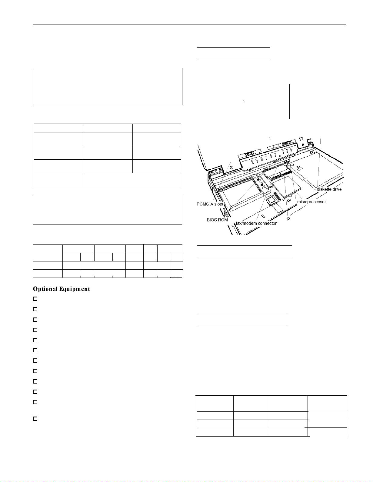
Major Subassemblies
memory module
\
LED panel (LED card or
audio/LED card under panel)
ower converter board
Physical Dimensions
Model Depth Width Height
in. mm in. mm in.
Monochrome 8.8
Color
0
4MB, 8MB, 16MB, or 20MB memory expansion module
0
520MB removable hard disk drive
0
14.4 internal data fax/ modem
0
16-bit stereo audio card
0
Additional NiMH batteries
0
Extra AC adapter or international AC adapter
0
Adapter for an automobile cigarette lighter
0
External battery charger
0
External keyboard
0
Numeric keypad
0
PCMCIA Type I, II, and III cards including flash RAM,
220 11.7 292 1.6
8.8 220 11.7 292 1.7
SRAM, modem, fax/ modem, and LAN cards
0
ActionPort Replicator.
mm lb kg
40 5.5 2.5
43 6 2.7
Weight
Memory Module Installation
The computer comes with 4MB of memory soldered on the
system board. If it has more than 4MB of memory, it already
has a memory module installed. Run the Setup program to
check the amount of memory installed. You can increase the
memory up to 24MB by removing the original module if
necessary and installing a 4, 8, 16, or 20MB memory module.
Microprocessor Upgrades
The computer’s processor can be upgraded by replacing the
original microprocessor with a higher-performance one. The
PGA socket on the main board can accept both a processor on
a daughter board and a processor installed directly in the
socket. A processor on a daughterboard may include 256KB
of external cache; all supported processors include 8KB of
internal cache. The following table lists the speed and voltage
of some of the microprocessors that can be installed.
Microprocessor voltage and frequency
Microprocessor Voltage (V)
Intel DX4/75 3.3 75
Intel DX4/100 3.3 100
Cx486DX2-V80 4.0
SUPPLY
Internal
frequency (MHz)
80
External
frequency (MHz)
25
33
40
12/9/94
AN800-3
Page 4

EPSON ActionNote 800 Series
Caution
When installing a new microprocessor, note that two holes
are labeled “pin 1.” If you are installing a processor chip
directly in the socket, insert pin 1 in the second row of holes
from the right. You will see an empty row of holes in the
socket to the right of the chip. If you are installing a
processor on a daughterboard, insert pin 1 in the outer row
of holes.
Microprocessor Switches
speed switch
CPU type switch
\
Processor speed switch
CPU type switch
Voltage switch
System Board Components
r
AN800-4
Page 5

EPSON ActionNote 800 Series
System Board Components
U4
U6
Ji
J2 Serial port connector
J3 VGA connector for external monitor
J4 Audio-In connector
J5 AC adapter connector
J6 Port replicator connector
J7 External keyboard/mouse connector
J8 Microphone connector
J9 LED and audio card connector
J10 Memory module connector
J11, J12, J13 LCD connectors
J14 Audio-Out connector
J15 Fax/modem connector
J16, J17 Main board connectors to power converter
J18 Speaker connector
J19 Trackpad connector
J20, J21 Internal keyboard connectors
J22 Diskette drive connector
J23 Hard disk drive connector
JP1, JP2 Daughterboard connectors
P1, P2 PCMCIA connectors
S1
S2 Speed selection switch
S4 CPU selection switch
Microprocessor
ROM BIOS
Parallel pod connector
Processor switch
Connector Pin Assignments
Parallel Port Connector (J1)
Pin No. Signal Name
1
2
3
4
5 D3
6 D4
7 D5
8 D6
9 D7
10
11
12 PE
13
NC
DO
D1
D2
ACK
BUSY
SLCT
Pin No.
14
15
16
17
18
19
20
21
22
23
24
25
Signal Name
AUTO FEED XT
ERROR
INIT
SLCT IN
GND
GND
GND
GND
GND
GND
GND
PRT SEL
Serial Port Connector(J2)
Pin
Pin
2
3
Signal
Carrier Detect
Receive Data
Transmit Data
Signal Pin
Ready
5
Signal Ground
6
Data Set Ready
7
8
9
VGA Connectorfor an External Monitor (J3)
Pin
1
2 Green
3
4 NC
5
Signal
Red
Blue
Ground
Signal
6
Ground
7 Ground 12 NC
8
Ground
9
NC
10
Ground
Pin
11
13
14
15
Pin
Power Converter Board Connector (22-pin male)
Pin No. Signal Name
1 to 4 GND
5
6
7
8
9
10
11
12 to 14
15
16
17
18
19
20 to 22 VA
Pin No. Signal Name
1 to 4
5 CHGLED
6
7
8 NC
9 NC
10 PWROFF
11 to 14
PSW
GND
DOCKON
SUSHDD
SUSCH
DOCKSW
INVPWR
+5 v
+3 v
+12 v
+3 v
CHGLED
INVPWR
VA
SWITCH
PWRON Reserved
GND
Description
Ground
Indicates the power switch
Ground
Indicates port replicator status
HIGH (active) when system is entering
suspend to hard disk mode
HIGH (active) when system is entering
suspend to DRAM mode
HIGH (active) when pod replicator is installed
For the inverter power source
For the system operating voltage
For the system operating voltage
For the flash ROM, etc.
Same as pin 15
An output pin to drive the green LED
Same as pin 11
A constant voltage form AC adapter
Description
Constant voltage from AC adapter
Output pin to drive the orange LED
To power on DC/DC converter
No connection
No connection
To bower off DC/DC converter
Ground
Signal
Request to Send4 Data Terminal
Clear to Send
Ring Indicator
Signal
NC
I
Horizontal Sync
Vertical Sync
NC
I
12/9/94
AN800-5
Page 6

EPSON ActionNote 800 Series
External Keyboard/Mouse Connector (J7)
Microphone Connector (J8)
Pin
1
2
Signal
AGND
MICIN 4
Pin
3
Signal
BMIC
BMIC
Fax/Modem Connector (J15)
Pin
5
Signal
MICIN
HDD IDE Connector (J23)
Pin No. Signal Name
1
2
3
4 GND
5
6
7
8
9
10
11
12
13
14
15
16 SD1
17
18
19
20 GND
RESET
GND
IDE D7
SD8
SD6
SD9
SD5
SD10
SD4
SD11
SD3
SD12
SD2
SD13
SD14
SD0
SD15
DRV
Pin No. Signal Name
21
22 IOWR
23 GND
24 IORD
25 GND
26 IOCHRDY
27 IRQ14
28 IOCS16
29
30 GND
31
32 SA0
33 SA2
34 HCS0
35
36 HDDLED
37 VCC5
38 VCC5
39 GND
40 VCC5
GND
SA1
GND
HCS1
Speaker Connector (J18)
Pin
1
Signal
GND
FDD Connector (522)
Pin
2
Memory Module Connector (J10)
Signal
SPK
AN800-6
12/9/94
Page 7

EPSON ActionNote 800 Series
PCMCIA Connector (P1 and P2)
Pin Signal Pin
1 GND 18
2 D3 19
12 A8
I 29
13
A13
I 30
14
A14
I 31
17
VCCX
I 34
Signal
VPP1 35
A16
A15
A12
A7
A6
A5
A4
A3
A2
A1
A0
DO
D1
D2
WP
GND
Pin
36
37
38
39
40
41
42
43
44
45
46
47
48
49
50
51
Signal
GND
CD1
D11
D12
D13
D14
D15
CE2
RFSH
IORD
IOWR
A17
A18
A19
A20
A21
VCCX
LED Card and Audio Card Connector (J9)
Pin
52
53
54
55
56
57
58
59
60
61
62
63
64
65
66
67
68
Signal
VPP2
A22
A23
A24
A25
RFU
RESET
WAIT
INPACK
REG
BVD2
BVD1
D8
D9
D10
CD2
GND
Audio Out Connector (J14)
LCD Connector (J11, 10-pin)
LCD Connector (J12, 15-pin)
LCD Connector (J13, 12-pin)
14
15
488ENA
SD1
29 IORD 44
30 SA7 45
Audio In Connector (J4)
LIN0
AEN
Processor Switch (S1)
48 AGND
49 IRQ5
50 LOUT0
51 IRQ7
52 LOUT1
53 IRQ9
54 AGND
55 IRQ10
56 BMIC
57 VCC5
58 MICIN
59 GND
60 AGND
12/9/94
AN800-7
Page 8

EPSON ActionNote 800 Series
AN800-8
12/9/94
Page 9

EPSON ActionNote 800 Series
Port Replicator Connector (J6) (continued)
System Memory Map
00000H
640KB base memory
0A0000H
128KB reserved for graphics display area
0C0000H
Reserved
0D0000H
Reserved
0E0000H
40KB for VGA BIOS
0EA000H
Power Management Utility
0F0000H
Hardware Interrupts
Interrupt Function
IRQ0
IRQ1
IRQ2 Cascade
IRQ3 COM2 (2F8H)
IRQ4 COM1 (3F8H)
IRQ5 Available
IRQ6 Diskette Controller
IRQ7
IRQ8 Clock/Calendar
IRQ9 Video
IRQ10 Available
IRQ11
IRQ12 Trackpad
IRQ13 Reserved for Coprocessor
IRQ14 Hard Disk Drive Controller
IRQ15 Available
Timer
Keyboard
LPT1
Available
64KB for system BIOS
100000H
FFE000H
Duplicated code assignment at address 0E0000
FFFFFFH
DMA Assignments
Channel Device
DMA0 Available
DMA1 Available
DMA2
DMA3
DMM4
DMA5 Available
DMA6 Available
DMA7
Diskette Controller
ECP
Cascade for CTRL 1
Available
Extended memory
12/9/94
AN800-9
Page 10

EPSON ActionNote 800 Series
System I/O Address Map
0
If you install a new hard disk drive and want to use the
Low Battery Save to HDD or Instant On options, you need
to leave sufficient space on the disk unpartitioned. The
amount of space should equal the system memory plus
2MB. After you run FDISK to partition the drive, you need
to run the PHDISK utility to configure the storage space
on the drive.
0
When the computer is turned on after using the Low
Battery Save to HDD or Instant On options, the PCMCIA
services are not reinitialized. The computer recognizes
SRAM PC cards, but does not recognize most other PC
cards. You must reboot to reinitialize the services.
Using an External Monitor
When you connect an external monitor, make sure you turn it
on before you turn on the computer. The ActionNote
automatically detects the external monitor and displays data
on its screen. Press Fn F10 to switch your display from the
monitor to the LCD screen or to display on both screens
simultaneously.
Using a Serial Mouse
If you connect a serial mouse, you must use the Setup
program to disable the built-in trackpad.
Installation/Support Tips
Using Low Battery Save to HDD and Instant On
0
The ActionNote 800 series hard disk drive is partitioned at
the factory so that these options can be used. A 25MB area
is set aside for the saved data; this ensures that there is
enough space for all memory configurations.
0
To prepare the hard disk drive, run the PHDISK utility,
located in the C:\ PM directory. Type the following
command at the DOS prompt and press Enter:
PHDISK/CREATE
Information Reference List
Engineering Change Notices
None
Technical Information Bulletins
None
Product Support bulletins
None
Related Documentation
400398600
400398700
PL-AN800 EPSON ActionNote 800 Series Parts Price List
TM-AN7800T
EPSON ActionNote 800 Series User’s Guide
Software Support Card
EPSON ActionNote 800 Series Service Manual
AN800-10
12/9/94
 Loading...