

Page 1
SERVICE MANUAL
SERVICE MANUAL
SERVICE MANUALSERVICE MANUAL
Color ink jet printer
EPSONStylusCOLOR660
SEJ99005
Page 2

Notice:
n
All rights reserved. No part of this ma nual may be reproduced, stored in a retrieval system, or transmitted in any form or b y any means,
electronic, mechanical, photocopying, recording, or otherwise, without the prior written permission of SEIKO EPSON CORPORATION.
n
The contents of this manual are subject to change without notice.
n
All efforthave been made to ensure the accuracy of the contents of this manual. However,should any errors be detected, SEIKO EPSON
would greatly appreciate being informed of them.
n
The above not withstanding SEIKO EPSON CORPORATION can assume no responsibility for any errors in this manual or the consequences
thereof.
EPSON is a registered trademark of SEIKO EPSON CORPORATION.
General Notice: Other product names used herein are for identification purpose only and may be trademarks or registered trademarks of their
respective owners. EPSON disclaims any and all rights in those marks.
Copyright © 1999 SEIKO EPSON CORPORATION. Printed in Japan.
Page 3

PRECAUTIONS
Precautionary notations throughout the text are categorized relative to 1)Personal injury and 2) damage to equipment.
DANGER
WARNING
The precautionary measures itemized below should always be observed when performing repair/maintenance procedures.
Signals a precaution which, if ignored, could result in serious or fatal personal injury. Great caution should be exercised in
performing procedures preceded by DANGER Headings.
Signals a precaution which, if ignored, could result in damage to equipment.
DANGER
1. ALWAYS DISCONNECT THE PRODUCT FROM THE POWE R SO URCE A ND PERIPHERAL DE VICES PERFO RMING ANY MAINTENANCE
OR REPAIR PROCEDURES.
2. NOWORK SHOULD BE PERFORMED ON THE UNIT B Y P ERSONS UNFAMILIAR WITH BASIC SAFETY MEASURES AS DICTATED FOR
ALL ELECTRONICS TECHNICIANS IN THEIR LINE OF WORK.
3. WHEN PERFORMING TESTING AS DICTATED WITHIN THIS MANUAL, DO NOT CONNE CT THE UNIT TO A POWER SOURCE UNTIL
INSTRUCTED TO DO SO. WHEN THE POWER SUPPLY CABLE MUST BE CONNECTED, USE EXTREME CA UTION IN WORK ING ON
POWER SUPPLY AND OTHER ELECTRONIC COMPONENTS.
WARNING
1. REPAIRS O N EPSON PRODUCT SHOULD BE PERFORMED ONLY BY AN EPSON CERTIFIED REPAIR TECHNICIAN.
2. MAKE CERTAIN THAT THE SOURCE VOLTAGES IS THE SAME A S THE RA TED V OLTAGE, LISTED ON THE SERIAL NUMBER/RATING
PLATE. IF THE EPSON PRODUCT HAS A PRIMARY AC RATING DIFFE RENT FROM AVAILABLE POWER SOURCE, DO N OT CONNECT IT
TO THE POWER SOURCE.
3. ALWAYS VERIFY THAT THE EPSON PRODUCT HAS BEEN DISC ONNECTED FRO M THE POWER SOURCE BEFORE REMOVING OR
REPLACING PRINTED CIRCUIT BOARDS AND/OR INDIVIDUAL CHIPS.
4. IN O RDE R TO PROTECT SENSITIVE MICROPROCESSORS AND CIRCUITRY, USE STATIC DISCHARGE EQUIPMENT, SUCH AS ANTISTATIC WRIST S TRA PS, WHEN ACCESSING INTERNAL COMPONENTS.
5. REPLACE MALFUNCTIONING COMPONENTS ONLY WITH THOSE COMP ONENTS B Y THE MA NUFACTUR E; INTRODUCTION OF
SECOND-SOURCE ICs OR OTHER NONAPPROVED COMPONENTS MAY DAMAGE THE PRO DUCT AND VOID ANY APPLICABLE EPSON
WARRANTY.
Page 4

PREFACE
This manual describes basic functions, theory of electrical and mechanical operations, maintenance and repair procedures of Stylus COLOR 660.
The instructions and procedures included herein are intended for the experienced repair technicians, and attention should be given to the precautions
on the preceding page. The chapters are organized as follows:
CHAPTER 1. PRODUCT DESCRIPTIONS
Provides a general overview and specifications of the product.
CHAPTER 2. OPERATING PRI NCIPLES
Describes the theory of electrical and mechanical operations of the product.
CHAPTER 3. TROUBLESHOOTING
Provides the step-by-step procedures for troubleshooting.
CHAPTER 4. DISASSEMBLY AND ASSEMBLY
Describes the step-by-step procedures for disassembling and assembling the
product.
CHAPTER 5. ADJUSTMENTS
Provides Epson-approved methods for adjustment.
CHAPTER 6. MAINTENANCE
Provides preventive maintenance procedures and the lists of Epson-approved
lubricants and adhesives required for servicing the product.
CHAPTER 7. APPENDIX
Provides the following additional information for reference:
• EEPROM Address Map
• Connector P i n Assignments
• Circuit Diagram
Page 5
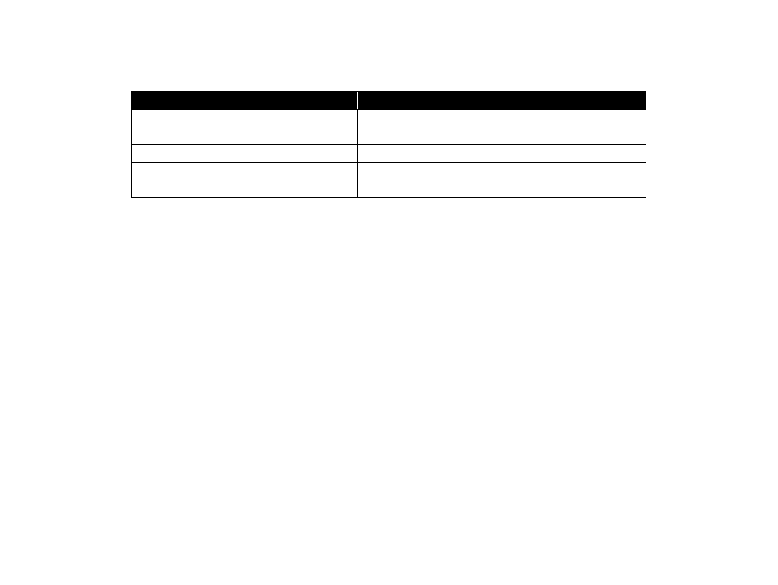
Revision Status
Revision Issued Date Description
A August 25, 1999 First Release
Page 6

PRODUCTDESCRIPTION
CHAPTER
1
Page 7
EPSON Stylus Color 66
0
A
n
7
1.1 FEATURES
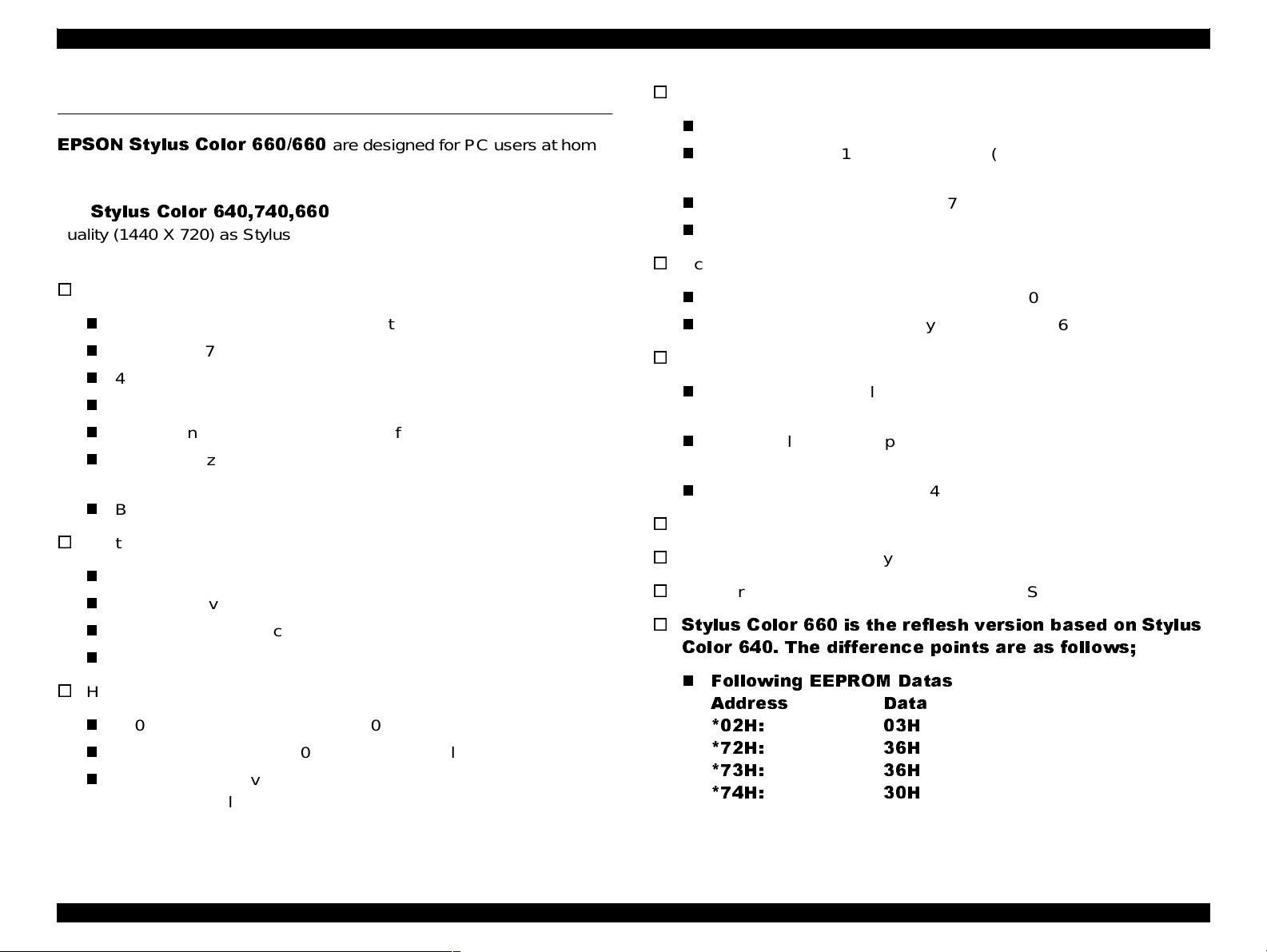
EPSON Stylus Color 660/660
and low price for hat high performance. Also, Stylus Color 440 printer
has the same high color print quality (720 X 720dpi) as Stylus ProXL,
Stylus Color 640,740,660
and
quality (1440 X 720) as Stylus Color 600 and Stylus Pro 5000. The
major printer features are;
o
High color print quality
n
720 (H) x 720 (V) dpi printing (for Stylus Color 440)
n
1440 (H) X 720 (V) dpi printing (for Stylus Color 640, 660, 740)
n
4 color printing (YMCK)
n
Traditional and New Microwave
n
Black 64 nozzles, CMY 21 nozzles (for Stylus Color 440)
n
Black 64 nozzles, CMY 32/color nozzles (for Stylus Color 640,
660)
n
Black 144 nozzles, CMY 48/color nozzles (for Stylus Color 740)
o
Built-in auto sheet feeder
n
Holds 100 cut-sheets (64g/m2)
n
Holds 10 envelopes
n
Holds 30 transparency films
n
Holds 65 special papers
o
High-speed print
n
200 cps (for Stylus Color 440, 740)
n
Normal 200 cps, Draft 400 cps (only for Stylus Color 640, 660)
n
By using head drive frequency 14.4KHz, printing speed is twice
faster than Stylus Color.
are designed for PC users at home
have the same high color print
Revision
o
Compact size
n
429mm (W) x 231mm (D) x 155mm (H) (for Stylus Color 440)
n
429mm (W) x 231mm (D) x 157mm (H) (for Stylus Color 640,
660)
n
429mm (W) x 261mm (D) x 157mm (H) (for Stylus Color 740)
n
Weight : 5.2Kg (for 3 models)
o
Acoustic noise
n
Approximately 45 dB (for Stylus Color 440)
n
Approximately 47 dB (for Stylus Color 640, 660, 740)
o
Interface
n
Bi-directional parallel I/F IEEE-1284 level 1 device (for 3
models)
n
Mac serial I/F up to approx. 1800 kbps (only for Stylus Color
740)
n
USB (only for Stylus Color 740)
o
One unit combined black and CMY head
o
Windows exclusive (for Stylus Color 440, 640, 660)
o
Standard, NLSP, 5 Scaleable fonts (only for Stylus Color 740)
o
Stylus Color 660 is the reflesh version based on Stylus
Color 640. The difference points are as follows;
n
Following EEPROM Datas
Address Data
*02H: 03H
*72H: 36H
*73H: 36H
*74H: 30H
Chapter 1 Product Descriptio
Page 8
EPSON Stylus Color 66
0
A
n
8
See the Table A-20 to A-26 for EEPROM address map of
EPSON Stylus Col or 440/640/740 Service Manual.
The rest contents of Product Description is the same as of EPSON
Stylus Color 640/660/740.
Revision
Chapter 1 Product Descriptio
Page 9
OPERATINGPRINCIPLES
CHAPTER
2
Page 10

EPSON Stylus Color 66
0
A
s
0
The contents of Operating Principles is the same as of EPSON Stylus
Color 640/660/740.
Revision
Chapter 2 OperatingPrinciple
1
Page 11

TROUBLESHOOTING
CHAPTER
3
Page 12

EPSON Stylus Color 66
0
A
g
2
The contents of Trouble Shooting is the same as of EPSON Stylus
Color 640/660/740.
Revision
Chapter 3 Trouble Shootin
1
Page 13

DISASSEMBLYANDASSEMBLY
CHAPTER
4
Page 14

EPSON Stylus Color 66
0
A
y
4
The co ntents of Disassembly and Assembly is the same as of EPSON
Stylus Color640/660/740.
Revision
Chapter 4 Disassemblyand Assembl
1
Page 15

ADJUSTMENT
CHAPTER
5
Page 16

EPSON Stylus Color 66
0
A
t
6
Revision
5.1 Overview
This chapter describes adjustments r equired for Stylus Color 640/660
when the printer is disassembled and assembled after repair. Refer to
Stylus Color 740/640/440 Service Manual for things that are not
described here.
5.1.1 Required Adjustments
Stylus Color 640/660 requires the following adjustments. (Refer to
Table 5-1) Perform any necessary adjustment referring to the figures
and procedures described throughout this chapter.
Table 5 -1 Adjustment Required
No. Adjustment Item Conditions
1 Parallelism Adjustment • When you replace or remove the Carriage
guide shaft.
• When you move the parallelism adjustment
bushing.
2 Initial Ink Charge • When you replace or remove the printhead.
3 Head Voltage ID Input • When you replace the printhead.
• When you replace the main board.
Note) The values stored in this address are not
erased by EEPROM reset operation.
4 Printing Head Angle
Adjustment
5 Bi-D Adjustment • When you replace or remove the printhead.
• When you replace or remove the printhead.
• When you move the printhead angle adjusting
lever.
• When you replace the main board.
• When you replace the CR Motor.
Table below shows the actions taken and required adjustments i n the
order to be performed.
Table 5 -2 Actions Taken and A djustment Required
No. ContentofOperation Adjustment Procedure
1 Removal of the printhead 1. Perform initial ink charge.
2. Perform printhead angle adjustment.
3. Perform Bi-d Adjustment.
2 Replacement of the printhead 1. Perform Vh voltage writing operation.
2. Perform initial ink charge.
3. Perform printhead angle adjustment.
4. Perform Bi-d Adjustment.
3 Replacement of the main board 1. Perform Vh voltage writing operation.
2. Perform Bi-d adjustment.
Note) After performing the above
adjustment, replace the following parts.
• Ink cartridge
• Waste Ink Pad
The above two kinds of software counter
are erased by replacing the Main board.
4 Replacement or Removal of the
Carriage Unit
5 Replace of the CR Motor 1. Perform Bi-d adjustment.
6 Replacement of the Printer
Mechanism
1. Perform parallel adjustment.
2. Perform printhead angle adjustment.
3. Perform Bi-d adjustment.
1. Perform Head Voltage ID Input.
2. Perform initial ink charge.
3. Perform Bi-d adjustment.
Chapter 5 Adjustmen
1
Page 17

EPSON Stylus Color 66
0
A
t
7
5.1.2 Adjustment Tools Required
Table 5-3 below shows adjustment tools for Stylus Co lor 640/660.
Table 5-3 Adjustment Tools Required
No. Nam e Adjustment Item Contents/Spec.
1 Thickness Gauge Parallelism Adjustment 1.04 mm
2 Adjustment
Program
CAUTION
n
Never use the bent (curved or t ilted) or rusty
thickness gauge.
n
Erase any dirt, grease or obstacles on the thickness
gauge before you use it.
Each Mechanism
Settings
ExclusiveProgram;
Stylus COLOR 600 640
660
Revision
Chapter 5 Adjustmen
1
Page 18

EPSON Stylus Color 66
0
A
t
8
5.2 Adjustment
This section explains the specific procedures for making the
adjustments using the exclusive adjustment program for Stylus Color
640/660.
5.2.1 Adjustment by Adjustment Program
For this printer, it is necessary to set the correct information for each
printer mechanism in order to maintain consistent printing function and
quality, eliminating differences among each printer mechanism's
characteristics.
Therefore, in case that the combination of the printer mechanism and
main board changes or the printhead is replaced during repair, you
must set and save the correct information to the main board, using the
exclusive adjustment program.
Main Menu
Adjustment
Market
destination check
Head voltage ID
input
Maintenance
Head cleaning
Initial ink charge
Print A4
pattern
Revision
Recovery
5.2.1.1 About Adjustment Program
The adjustment program (Program name: Stylus COLOR 600 640 660)
enables you to set various values correctly to prevent malfunction and
fluctuation of printing quality and printing function caused by difference
in components and assemblywhen the printer components are
replaced during repairs. Basic adjustment menu in this program are
shown in Figure 5-1. Options in the Program.
NOTE:This Adjustment Program can not be used in Windows NT
and Dos environment.
Chapter 5 Adjustmen
Head angular
adjustment
Bi-Directional
adjustment
Indication of the
counter value
Figure 5-1. Options in the Program
1
Page 19

EPSON Stylus Color 66
0
A
t
9
Revision
5.2.1.2 Entering Stylus COLOR 660 SERVICE PROGRAM
To perform any adjustment, you need to enter the Stylus COLOR 660
SERVICE PROGRAM
steps will bring you to the service program screen.
1. Connect the printer and PC and turn on the printer.
2. Insert Disk 1 for the adjustment program to the floppy disk d rive.
3. Execute Setup.exe of Disk 1.
4. The Setup Wizard for the adjustment program “EPSON Stylus
COLOR 600/640/660 SERVICE PROGRAM Version 4.0” starts,and
you can follow the direction indicated by the wizard.
5. The Setup Wizard says “Setup Ne eds The Next Disk.”
6. Take out Disk 1 and insert Disk 2.
7. Program will be installed in your appointed folder.
8. Go to the appointed folder and open the adjustment program.
first. Read the following instructions and these
9. The following screen appears.
Figure 5-2. Initial Screen (1)
10. Choose Stylus Color 660, and click OK. By doing so, the model
name will be written in the EEPROM.
NOTE: If you select wrong model name in the above menu between
Stylus COLOR 640 and 660, the model name will be written
in the EEPROM anyway because SC 640 and 660 have
compatibility. Be careful not to choose wrong model name.
The wrong model name will not be written in EEPROM
between SC 660 and SC 640 or between SC 600 and
SC 660.
Chapter 5 Adjustmen
1
Page 20

EPSON Stylus Color 66
0
A
t
0
Revision
11. In the next screen, choose th e mar ket destination according to the
market.
n
Standard: All the market except ESP.India and Korea
n
ESP.India: for ESP India
n
Korea: for EKL
NOTE:When you choose the market destination, the respective dot
size used in the economy mode will be written in the
EEPROM (6E<H>).
Default setting: Normal x 2 dot (Standard)
Normal x 1 dot (ESP. India)
NOTE:When Korea is selected, the setting will be the same as in
the case Standard is selected.
13. Following screen appears.
Figure 5-4. Initial Screen (3)
Figure 5-3. Initial Screen (2)
12. Click OK.
Chapter 5 Adjustmen
If you want to check t his model name, choose “Check
this model name” and click OK. (See step 14)
If you do not ne ed to check the m odel name or finished
checking, s elect “Boot this program”. (See step 17)
2
Page 21

EPSON Stylus Color 66
0
A
t
Revision
14. When you select “Check this model name”, the following screen
appears.
NOTE:While checking the model name, keep the printer ON.
15. After a few seconds, the model name appears on the screen shown
below.
Figure 5-6. Checking the model name (2)
Figure 5-5. Checking the m odel name (1)
Chapter 5 Adjustmen
16. Press “OK (Esc)” to go back to the initial screen (3) (Figure 5-4).
NOTE:If the Model name is wrong, choose the right model name on
Figure 5-2.
21
Page 22

EPSON Stylus Color 66
0
A
t
2
17. In the initial screen (3) (Figure 5-4), select “Boot this program” and
you will enter Stylus COLOR 660 SERVICE PROGRAM.
18. Stylus COLOR 660 SERVICE PROGRAM shown below appears.
Revision
Figure 5-7. Stylus COLOR 660 SERVICE PROGRAM
Chapter 5 Adjustmen
2
Page 23

EPSON Stylus Color 66
0
A
t
3
Revision
5.2.1.3 Initial Ink Charge
There is no ink charged in the ink path of a spare printhead and printer
mechanism. Therefore, after you replaced any of the following units,
perform initial ink charge and return the printer after making sure that
ink is ejected correctly from the printhead.
n
After replacing the printer mechanism
n
After replacing or removing the printhead
1. On the Stylus COLOR 660 SERVICE PROGRAM, select
maintenance menu.
2. Select “Initial ink charge” from the maintenance menu. The following
screen appears.
Figure 5-9. Initial Ink Charge
CAUTION
Before you set the initial ink charge, replace the
installed cartridges with new ones, because the ink
amount used for the initial ink charge operation is so
large.
3. Click OK, and the printer enters the initial ink charge sequence.
(It takes 90 seconds for this operation to complete the whole
Figure 5-8. Maintenance Menu
Chapter 5 Adjustmen
sequence.)
2
Page 24

EPSON Stylus Color 66
0
A
t
4
Revision
5.2.1.4 Head Cleaning
Stylus Color 660 have no dummy cleaning sequence called CL3, which
was performed to prevent ink from being unnecessarily consumed when
cleaning was repeated without any printout. However, Stylus Color 660
is alternatively equipped with the strongest cleaning sequence CL2
contained in this adjustment program. With this sequence, you can
forcibly solve the clogged nozzle problem caused by viscous ink.
CAUTION
1. On Stylus COLOR 660 SERVICE PROGRAM, select Maintenance
menu.
If you can not recover the clogged nozzles de spite you
performed CL2 ope ration, enter the Initial ink charge
sequence by referring to Section 5.2.1.3.
2. From Maintenance menu, select “Head cleaning”. The following
screen appears.
Figure 5-11. Head Cleaning
3. Click OK. The printer enters the CL2 sequence. (It takes60seconds
for the process to complete.)
Figure 5-10. Maintenance Menu
Chapter 5 Adjustmen
2
Page 25

EPSON Stylus Color 66
0
A
t
5
Revision
5.2.1.5 Indication of the counter value
The program provided with this manual can let you confirm or clear the
current protection counter value.
[Confirming the current protection counter value]
1. On Stylus COLOR 660 SERVICE PROGRAM, select the
Maintenance menu.
2. From the maintenance menu, select “Indication of the counter value.
The screen below appears”.
Figure 5-13. Protection Counter CHECK/CLEAR
Figure 5-12. Maintenance Menu
Chapter 5 Adjustmen
2
Page 26

EPSON Stylus Color 66
0
A
t
6
Revision
3. Click “Check th e present counter values”. Th e screen below
appears.
[Clearing the current protection counter value]
CAUTION
Be sure to replace the ins talled waste ink pad with a
new one after or before you clear the current protection
counter value.
1. From the maintenance menu (Figure 5-8), select “Indication of the
counter value”. The Protection counter CHECK / CLEAR Screen
shown in Figure 5-13 appears.
2. Click “Clear the protect counter values” on the screen. The screen
shown below appears.
Figure 5-14. Che ck the present counter values
4. If the present counter value is over 9800 points, advice your
customer to replace the Waste ink drain pad with new one.
Chapter 5 Adjustmen
Figure 5-15. Clear the protection counter values
3. Click OK. At the bottom of the screen, it says “The protect counter
has been reset to zero”.
2
Page 27

EPSON Stylus Color 66
0
A
t
7
Revision
5.2.1.6 Market Destination
For Stylus Color 660, the market destination is originally set.
1. To check the market destination, click “Market destination check” on
the a djustment menu shown below.
Figure 5-16. Adjustment Menu
2. The Market Destination Check screen shown below appears.
Figure 5-17. Ma rket Destination check
3. Click OK. After a few seconds, market destination appears at the
bottom.
NOTE:If the market destination is wrong, click the correct market
destination in Figure 5-3. The correct information will be
written in the EEPROM.
Chapter 5 Adjustmen
2
Page 28

EPSON Stylus Color 66
0
A
t
8
Revision
5.2.1.7 Head Voltage ID Input
Head voltage value adjustment function enables you to write printhead
ID. This operation is considered the most important to maintain proper
printhead operation. If an ID is not written correctly, it results in white or
color lines and also gives bad influence on dot weight. This adjustment
is required in the following cases.
n
When exchanging the main board
n
When exchanging the printhead
n
When exchanging the printer mechanism
CAUTION
1. When replacing any of the parts above, make a note of VH voltage
ID appointed in advance. You can find the VH voltage ID on the
following position:
n
Before or a fter performing this operation, refer to the
Table 5 -2 on page 16 and perform any appropriate
adjustments or operations.
Printhead: On the side face of the printhead.
4. The following screen appears.
Figure 5-18. He ad Voltage ID Input (1)
n
Printer mechanism: On the label of the packing box of the
printer mechanism.
2. On Stylus COLOR 660 SERVICE PROGRAM, select Adjustment
menu (Figure 5-16).
3. Select “Head voltage ID input”.
Chapter 5 Adjustmen
2
Page 29

EPSON Stylus Color 66
0
A
t
9
Revision
5. Select “Change data”, and the following screen appears.
Figure 5-19. He ad voltage ID input (2)
7. Select “Check present data” on the previous screen (Figure 5-18).
The screen below appears.
6. Input the new head voltage ID number, and click OK. The new ID
number will be automatically written in the EEPROM.
Chapter 5 Adjustmen
Figure 5-20. Check present data
8. Click OK, and check the head voltage ID is renewed.
NOTE:Although the possibility is quite low, if the logic circuit is still
alive when replacing the main board, you can read Head ID
of the failed main board by using this function without
removing the head.
2
Page 30

EPSON Stylus Color 66
0
A
t
0
5.2.1.8 Head Angular Adjustment
This adjustment is required in the following cases.
n
When a printhead is replaced.
n
When the carriage unit is replaced.
n
When the angle adjustment lever is moved.
By moving the angle adjustment lever, you can adjust the printhead
angle without removing the ink cartridge.
Print the check pattern in the adjustment program to determine the
angle degree needed for the printhead. Then move the adjustment lever
in the carriage unit to set the printhead angle referring to the printed
check pattern.
Revision
CAUTION
Before or a fter performing this operation, refer to
Table 5 -2 on page 16 and perform appropriate
adjustments or operations.
1. Remove the upper case from the main unit. (Refer to Chapter 4.)
NOTE:If you perform this adjustment with the upper case installed,
select “Move the carriage to the head angular adjustment”
on Head Angular Adjustment (Figure 5-21) before loosening
the screw.
2. Select “Head angular adjustment” in the adjustment menu(Figure
5-16). The following screen appears.
Figure 5-21. Head Angular Adjustment
3. Select “Print the head angular adjustment p attern”. The printer
prints the head angular adjustment pattern (Figure 5-22).
Head Angular Adjustment P attern (BK-M)
Figure 5-22. Sam ple of Head Angular Adjustment Pattern
4. Move the carriage to the head angular adjustment.
For Stylus CO lor 660, the head angular adjustment is at the center,
not at the ink cartridge replacing position.
Chapter 5 Adjustmen
3
Page 31

EPSON Stylus Color 66
0
A
t
Revision
5. Loosen the screw securing the printhead on the carriage. (You don't
need to remove it completely.)
Printhead securing screw
Figure 5-23. Screw Position
6. Look at the black/magenta combination in the pattern and move the
adjusting lever to make the magenta lines stay b etween the black
lines with even space. The figure below shows how the pattern
changes as the adjusting lever moves right (rear) or left (front).
To move this down
move the lever
Correct condition = evenly spaced
to the right (rear)
To move th is up
move th e lever
to the left (front)
NOTE:Make sure to loosen this screw. Otherwise, the printhead
angle will no change even if the adjusting lever moves.
CHECK
POINT
If more than five minutes passed after moving the
carriage, the CR motor becomes OFF and cannot
accept the comm and to move the carriage.
In order to avoid this, the program indicates the
message. When the message “The printer has been
left alone for 5 minutes” appears at the bottom of the
head a ngular adjustment screen, click the OK button.
Chapter 5 Adjustmen
Adjusting Lever
Figure 5-24.
Lever Operation and Corresponding Change in Pattern
7. Repeat the procedures from step 3 to step 6 until th e combination
pattern of black/magenta is correct.
8. After completing the adjustment, tighten the loosened screw, and
reinstall the upper case only when you remove it.
31
Page 32

EPSON Stylus Color 66
0
A
t
2
9. After tighten the screw, print the check pattern again to confirm.
If there is any gap, make the adjustment again.
Revision
CHECK
POINT
If a certain amount of gap is generated at a certain
direction by tightening the screw, make an adjustment
considering the expected gap amount and tighten the
screw.
Chapter 5 Adjustmen
3
Page 33

EPSON Stylus Color 66
0
A
t
3
Revision
5.2.1.9 Bi-D Adjustment
You perform this adjustment to correct differences in printing positions,
which is caused by incorrect printing timing in right and left directions
during the Bi-directional printing. Therefore, you are required to perform
this adjustment after performing the following operations.
n
Replacing the Print mechanism
n
Replacing the main board
n
Replacing the CR motor
n
Replacing the Carriage Assembly
n
Replacing g the Printhead
1. Select “Bi-Directional Adjustment” in the adjustment menu (Figure
5-16). The following screen appears.
2. Select “Print the Bi-D adjustment p attern” on the screen, and the
screen bellow appears.
Figure 5-26. Print the Bi-D pattern
3. Click OK. The printer starts printing a Bi-D adjustment pattern. (See
the sample pattern in the following page.)
NOTE:As shown in the sample, gaps between passes are
sometimes created in different directions among patterns.
This unexpected change in direction is caused by an ink jet
printer-specific reason, which is an ink jet printer inevitably
performs a periodical cleaning specified by the flashing timer
even during Bi-D pattern printing, so that the printing
Figure 5-25. Bi-D Adjustment Menu
direction suddenly changes. However, this directional
difference among Bi-D patterns should not be considered,
and you can always confirm and adjust the pattern correctly
by referring to gap amount only.
Chapter 5 Adjustmen
3
Page 34

EPSON Stylus Color 66
0
A
t
4
200 CPS Bi-D Pattern: Data = -2
Left Gap
200 CPS Bi-D Pattern: Data = 0
Right Gap
Revision
4. Go back to “Bi-D A djustment” screen (Figure 5-25), select “Adjust”.
The screen below appears.
200 CPS Bi-D Pattern: Data = 2
5. The value “0” (blue) appears in the center of the screen and
changes up/down every time you press the Up/Down arrow key.
If you put plus number, the 2nd path pattern shifts to the left; if you
put minus number, the 2nd path pattern shifts to the right.
Using the keys, apply the number for the most properly aligned
pattern in the Bi-D adjustment pattern print.
6. After you set the value correctly, click OK, and the program stores
Figure 5-27. Bi-D ADjustment Pattern Sample
the selected value.
7. Click “Previous”. The current screen returns to the Bi-D adjustment
menu. (See Figure 5-25.)
8. Repeat the procedure from step 2 to step 7 until the Bi-D adjustment
pattern is correct.
Chapter 5 Adjustmen
Figure 5-28. Adjust
3
Page 35

EPSON Stylus Color 66
0
A
t
5
Revision
5.2.1.10 Print A4 Pattern
For S tylus Color 660, you can check all the adjustment has done
correctly by executing “print A4 pattern”.
1. In the following screen, click OK.
2. The printer starts printing the pattern, and the screen below
appears.
Figure 5-30. Print A4 Pattern (2)
3. After printing all patterns indicated in the menu, press “Previous”.
Figure 5-29. P rint A4 Pattern (1)
NOTE: If you find any white streaks or shades shown below, do the
adjustment again.
Figure 5-31. Nozzle Check (BK)
Chapter 5 Adjustmen
3
Page 36

EPSON Stylus Color 66
0
A
t
6
Revision
5.2.1.11 Recovery
By using this program, you can clean the clogged nozzle.
Stylus Color 660 alternately executes CL2 and Nozzle Check Pattern.
1. In the following screen, click OK.
2. The following screen appears. Click OK.
Figure 5-33. Recovery routine for clogged nozzle
3. The printer executes Head Cleaning and prints out the nozzle check
pattern below.
Figure 5-32. Recovery
NOTE: You can do this operation repeatedly. The program counts
how many times the operation is executed.
Figure 5-34. All Nozzle Test Pattern
Chapter 5 Adjustmen
3
Page 37

MAINTENANCE
CHAPTER
6
Page 38

EPSON Stylus Color 66
0
A
e
8
The contents of Maintenance is the same as of EPSON Stylus Color
640/660/740.
Revision
Chapter 6 Maintenanc
3
Page 39
APPENDIX
CHAPTER
7
Page 40

EPSON Stylus Color 66
0
A
x
0
The contents of Appendix is the same as of EPSON Stylus Color 640/
660/740.
Revision
Chapter 7 Appendi
4
 Loading...