

Page 1
Epson ActionDesk 4000
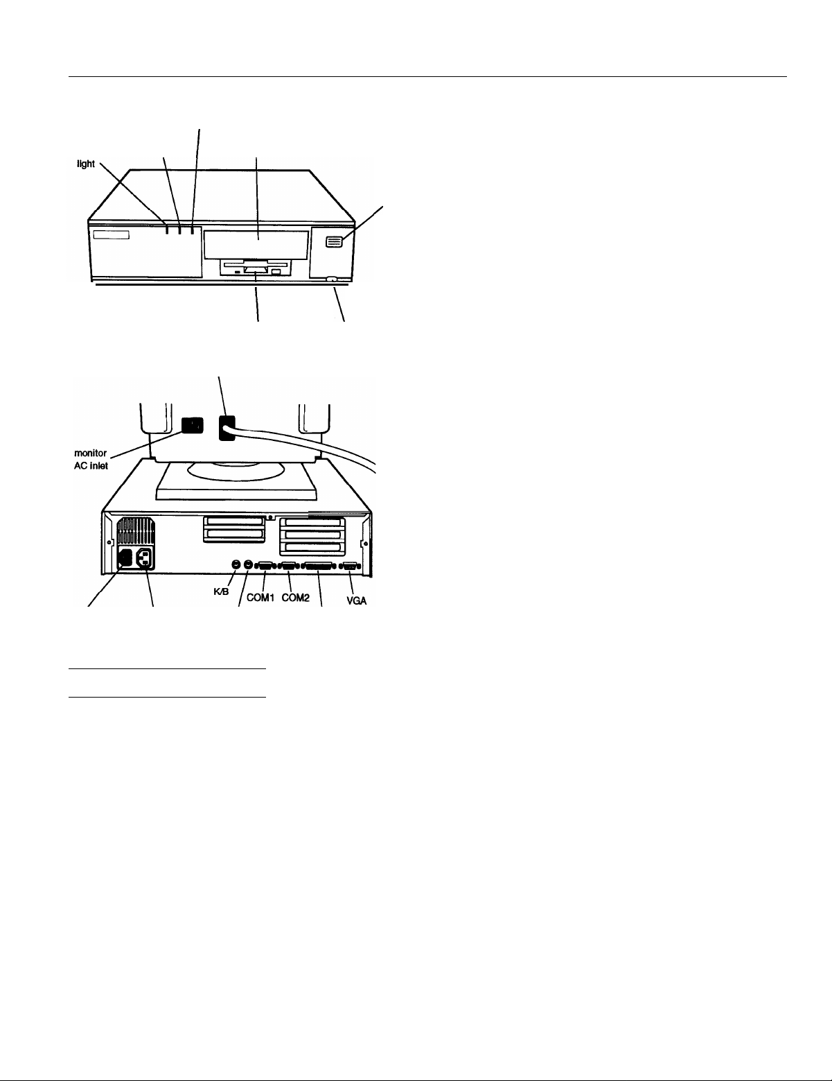
power
speed access
(TURBO)
light
hard disk
\
I
monitor cable
light
optional drive bay
I
I
diskette drive
\
reset button
power
button
/
ROM
Video RAM
Shadow RAM
Cache
Math
coprocessor
Clock/calendar
Controllers
Video
128KB system BIOS, video BIOS, and
SETUP code located in EPROM on main
system board
1MB DRAM on main system board;
expandable to 2MB using two ZIP chips
Supports shadowing of system and video
BIOS ROM into RAM
8KB of internal cache; supports 64KB,
128KB, or 256KB of external cache using
28-pin, 8 x 8, 20ns DIP chips or 28-pin,
32 x 8, 20ns DIP chips
On DX and DX2 systems, math
coprocessor built into the microprocessor
Contained in the 82C491 system controller
chip along with 64 bytes of CMOS RAM
backed up by a soldered NiCad
rechargeable battery
Cirrus GD5426 high speed super VGA
local bus controller with True Color
support; with the standard 1MB of video
RAM, supports resolutions up to
1280 x 1024 in 16 colors; with 2MB of
video RAM installed, supports resolutions
up to 1280 x 1024 in 256 colors
AC inlet
AC outlet
MOUSE
PARALLEL
Computer Specifications
CPU and Memory
32-bit CPU
System speed
Memory
Intel 486SX/25, 486SX/33, 486DX/33,
486DX2/50, or 486DX2/66 microprocessor
Fast and slow speeds available; fast is the
speed of the microprocessor, slow is
8 MHz; speed selection through keyboard
commands or jumper setting
4MB RAM standard on a SIMM;
expandable to 64MB using 1MB, 2MB,
4MB, 8MB, 16MB, and 32MB SIMMs;
SIMMs must be tin-plated, 72-pin, 32-bit
or 36bit, fast-page mode type with access
speed of 80ns (with 1 wait state) or 70ns or
faster (with 0 wait state)
Diskette
Hard disk
Interfaces
Monitor
Parallel
Serial
Keyboard
Mouse
Controller on main system board supports
up to two diskette drives
High-speed, 32-bit local bus IDE interface
on main system board supports up to two
IDE hard disk drives with built-in
controller; BIOS provides hard disk
auto-sensing function
VGA interface for fixed or multifrequency monitor built into system
board; 15-pin, D-shell connector
One standard &bit parallel interface built
into main system board; 25-pin, D-shell
connector
Two RS-232C, programmable,
asynchronous interfaces built into main
system board; 9-pin, D-shell connectors
PS/2 compatible keyboard interface built
into main system board; 6-pin, mini DIN
connector
PS/2 compatible mouse interface built
into main system board; 6-pin mini DIN
connector
9/15/93
Epson ActionDesk 4000-1
Page 2
Epson ActionDesk 4000
Option slots
Speaker
Mass storage
Diskette drives
Hard disk
drives
Other devices
Three 16-bit, full-length and two &bit,
half-length I/O expansion slots, ISA
compatible, 8.33 MHz bus speed
Internal
Internal mounts:
Two 3%-inch wide, third-height
(one-inch) drives
Externally accessible mounts:
One
one
314-inch
51/-inch
wide, third-height drive and
wide, half-height drive
3.5-inch diskette drive, l.44MB
(highdensity) storage capacity
5.25-inch diskette drive, 1.2MB
(high-density) storage capacity
3.5-inch diskette drive, 720KB
(double-density) storage capacity
5.25-inch diskette drive, 360KB
(double-density) storage capacity
314-inch form factor hard disk drive(s), up
to half-height size; maximum of two drives
Half-height tape drive, CD-ROM, or other
storage device;
5Y&.nch
or
3%-&h
with
mounting frames
Power Supply
Type
Input ranges
Maximum
outputs
Frequency
Cables
Option Slot Power Limits
Maximum current
For all
slots
65 Watt, UL listed, fan-cooled
100-240 VAC
+5 VDC at 7.5 Amps, -5 VDC at 0.1 Amps,
+12 VDC at 2.0 Amps, -12 VDC at 0.2
Amps
50/60 Hz
Two to main system board; four to mass
storage devices
+5Volts
4.6
Amps
-5 volts
0.1 Amps 1.6 Amps
+12 volts
Environmental Requirements
Altitude
-330to9,900
(-100 to 3,000 m) (-100 to 12,000 m) (-100 to 12,000 m)
n
-330to39,600ft-330 to 39,600 n
-12 volts
0.1
Amps
Keyboard
Detachable, two-position height; 101 or 102
sculpted keys; country-dependent main
typewriter keyboard; numeric /cursor
control keypad; four-key cursor control
keypad; 12 function keys
SETUP
Program
System Security
Stored in ROM; accessible by pressing
F2 during boot
User and supervisor level passwords
(8 characters) available for system boot or
diskette access
Physical Characteristics
Width
Depth
Height
Weight
15.6 inches (396 mm)
14.5 inches (368 mm)
4.1 inches (104 mm)
15 lb (6.8 kg),
without drives or keyboard
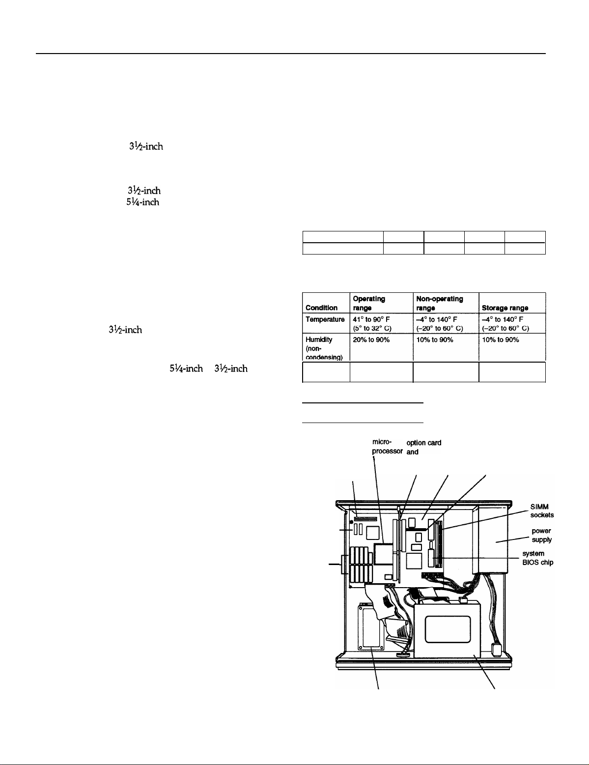
Major Subassemblies
Video
memory
optional
external
cache
sockets
optional
video
memory
sockets
-
zi:i,,
I
Eoncard
connector system
board board
diskette drive
connector
Epson ActionDesk 4000-2
9/15/93
hard disk drive
mounting bracket
drive bays
Page 3
Epson ActionDesk 4000
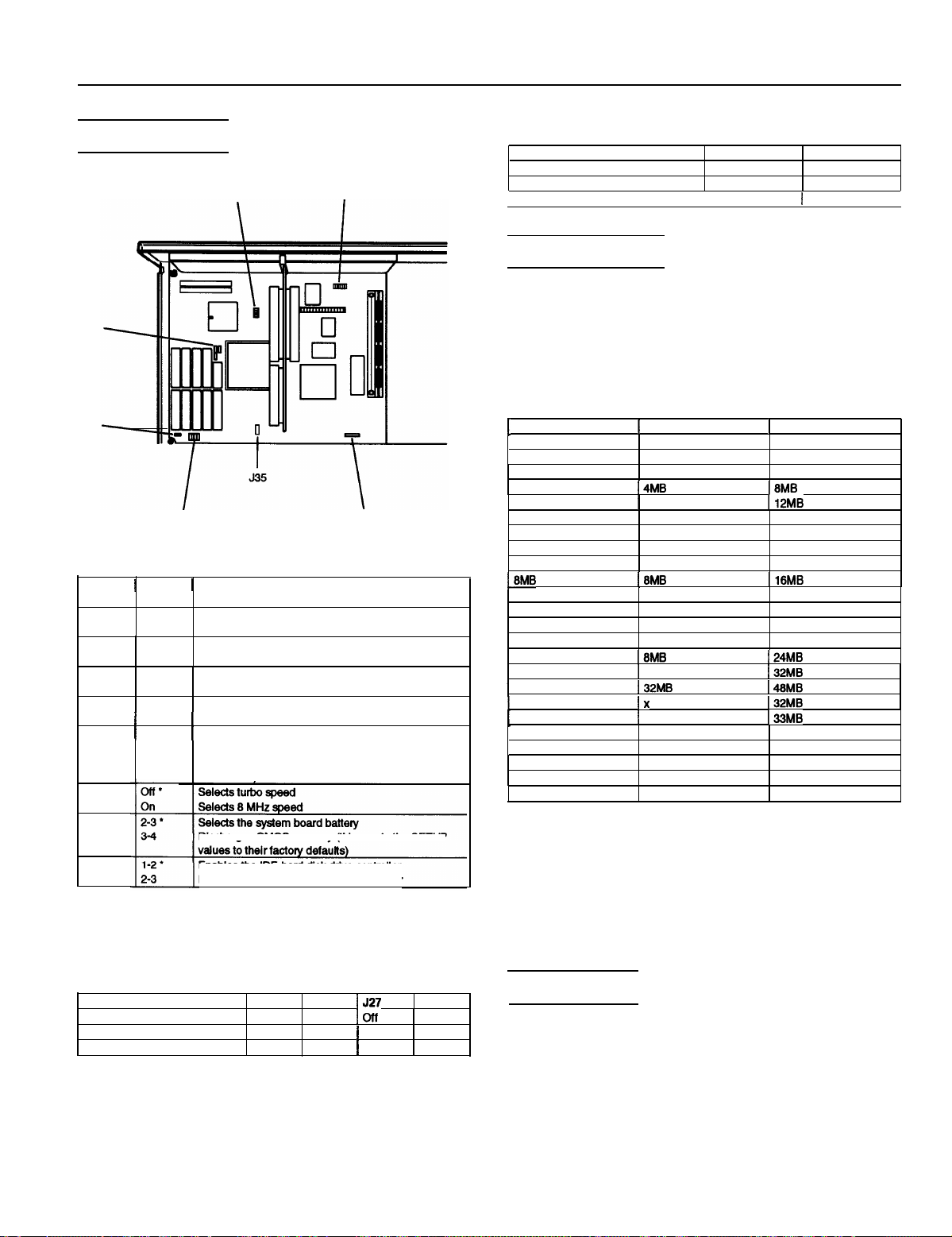
Jumper Settings
J16
J17
J19
J22
J25, J26, J27, J28
Jumper settings
Jumper I Jumper
number
J5
J6
J7
J8
J16
J22
setting Function
1-2*
2-3
1-2*
2-3
1-2*
2-3
1-2
1
2-3
1
1-2l **1Selects a CPU dock speed of 33 MHz (486SX/33,
5-6
I
Assigns PARALLEL port as LPT1
Assigns PARALLEL port as LPT2
Assigns COM1 serial port as COM1
Assigns COM1 serial port as COM3 **
Assigns COM2 serial port as COM2
Assigns COM2 serial port as COM4* *
l
Enables diskette drive controller
1
Disables diskette drive controller
486DX33, 486DX2/66)
Selects a CPU dock speed of 25 MHz (486SX/25,
486DX2/50)
J5, J6, J7, J8
I
J34
Processor type jumper settings
Processor type
486DX/DX2
466SX
I
487SX
J17 J19
1-2, 3-4
2-3
I 1-2.3-4
1
2-3
1-2
off
I
SIMM Installation
Your computer comes with 4MB of memory on a SIMM. You
can increase the memory up to 64MB by installing 1MB,
2MB, 4MB, 8MB, 16MB, and 32MB SIMMs in the computer’s
two SIMM sockets. The following table shows the possible
SIMM configurations; do not install memory in any other
configuration.
SIMM configuration
1
BANK 0
4MB
4MB
4MB 2MB
4MB
4MB
8MB
8MB
8MB 2MB 10MB
8MB
18MB
16MB
16MB 1MB
16MB
16MB
16MB
16MB
1
16MB
32MB
32MB
32MB 2MB 34MB
32MB 4MB
32MB 8MB 40MB
32MB
32MB
1
BANK 1
X
1MB
I4MB I8MB
1
8MB
X
1MB
4MB
I8MB I16MB
X
2MB 18MB
4MB
I8MB
I
16MB
I32MB
Ix
1
1MB
16MB
32MB
1
Total memory
4MB
5MB
6MB
112MB
8MB
9MB
12MB
16MB
17MB
20MB
I24MB
I32MB
148MB
I32MB
133MB
36MB
48MB
64MB
J34
J35
* Factory setting
**
You can use MS-DOS to automatically reassign parallel and serial ports.
Check your MS-DOS manual for more Information.
l
**
Setting depends on CPU
Discharges CMOS memory (this resets the SETUP
Enables the IDE hard disk drive controller
Disables the IDE hard disk drive controller
External cache jumper settings*
Cache size
64KB
128KB
256KB
l
If you have no external cache installed, the position of these jumpers does
not matter.
J25
1-2
2-3
2-3
J25
1-2
1-2
2-3
1527 J28
loff
1
1-2 1-2
1
2-3 2-3
2-3
9/15/93
Use only tin-plated, 32-bit or 36-bit, 72-pin, fast-page mode
SIMMs that operate at an access speed of 80ns (nanoseconds)
or faster. Be sure all the SIMMs operate at the same speed.
SIMMs that are 80ns must operate with 1 wait state; 70ns or
faster SIMMs can operate with 0 wait state. (To add a wait
state, select the DRAM wait state option from the
Advanced Chipset Control option in SETUP.)
Video Memory
The ActionDesk 4000 comes with 1MB of video memory. You
can increase the video memory to 2MB by installing two
video DRAM, 40-pin, 256KB x 16-bit, ZIP (Zig-zag Inline
Package) chips.
For the memory to work properly, you must install one chip
in each socket.
Epson ActionDesk 4000-3
Page 4

Epson ActionDesk 4000
External Cache
You can install 64KB, 128KB, or 256KB of external cache on
the ActionDesk 4000.
Cl
To install 64KB of external cache, use eight SRAM, 28-pin,
8 x 8, 20ns DIP chips, and one 8 x 8, 20ns tag chip
0
To install 128KB of external cache, use four SRAM, 28-pin,
32 x 8, 20ns DIP chips, and one 8 x 8, 20ns tag chip
Cl
To install 256KB of external cache, use eight SRAM,
28-pin, 32 x 8, 20ns DIP chips, and one 32 x 8, 20ns tag
Chip.
For the cache memory to work properly, you must install
chips in the following configuration (each bank contains four
cache memory sockets).
Cache memory configurations
1
BANK 0
U20,21,22,23
8Kx8
32Kx8
32Kx8
Microprocessor Upgrades
1
BANK 1
U29,30,31,32 U36
8Kx8
X
32Kx8
1
Tag SRAM
8Kx8
8Kx8
32Kx8
1
Total cache
64KB
128KB
256KB
1
Hard Disk Drive Types
The ActionDesk 4000 comes with a hard disk auto-sensing
feature. When you press Enter with the cursor positioned on
the Autotype Fixed
detects the type of hard disk drive you have installed and
fills in the drive information using values in the following
table.
Hard disk drive types
Disk
option in SETUP, the system
The computer’s processor can be upgraded by replacing the
existing microprocessor with a faster one. You can either
purchase an upgrade kit from Epson or buy the individual
components separately, as listed in the following table.
Microprocessor upgrade components
Part
486SX/33 processor
486DX/33 processor
486DX2/50 processor
486DX2/66 processor
Heat sink*
Heat sink with fan**
l
For the DX/33 processor
**
For the DX2/50 and the DX2/66 processor
Manufacturer
Intel
Intel
Intel
Intel
Tennmax Trading Corp. HS-486DX33-9
Tennmax Trading Corp.
I Manufacturer’s I
part number
A80486SX-33
A80486DX-33
A80486DX2-50
A80486DX2-66
897-4545-061
DX/33, DX2/50, and DX2/66 processor upgrades require a
heat sink. If the fan is mounted on the heat sink for the
DX2/50 and DX2/66 processors, you cannot use the last
option slot. Also, make sure jumpers J16, J17, and J19 are set
correctly for the new processor. (See page 3.)
*
Actual formatted size may be slightly different than size on drive label; you
cannot change this value.
Epson ActionDesk 4000-4
9/15/93
Page 5

Epson ActionDesk 4000
Some older or preformatted drives do not support the
auto-sensing feature. If the parameters displayed do not
match the parameters of your hard disk drive, you can define
your own drive type in SETUP. Use the following values for
Epson-supplied hard disk drives.
Epson-supplied hard disk drive types
Actual formatted size may be slightly different than size on drive label.
l
Installation/Support Tips
Installing Diskette Drives
Make sure that the drive type has been correctly selected in
the SETUP program.
Installing Hard Disk Drives
It is recommended that a 16-bit, AT-type hard disk
controller be used if you are installing a drive that cannot
use the embedded IDE interface. If you install a non-IDE
hard disk drive and controller card, you need to disable
the built-in IDE hard disk drive interface by moving
jumper J35 to position 2-3.
To take advantage of the local bus IDE interface, your
hard disk drive must support a 32-bit data path that uses
double-word I/O.
When installing a hard disk drive, see the hard disk drive
type tables on pages 4 and 5 and use the auto-sensing
feature in SETUP to select the correct type number for the
drive. If the auto-sensing feature does not produce a
match for the drive, you can define your own drive type
by selecting User as the type and entering the drive’s
exact parameters. Also make sure you have installed the
IDE drivers on your hard disk and that the CONFIG.SYS
file loads the drivers.
If you plan to install two hard disk drives in the internal
bays, you must use flat-head screws (#6-32UNC x 8
FH,M,+) to secure the top drive to the mounting bracket.
If you are going to install NetWare 286, version 2.2, and
you plan to assign a userdefined drive type, install two
NetWare IDE drivers (IDE.DSK and IDE.OBJ) available by
downloading IDE286.ZlP from Netwire on CompuServe.
Alternatively, assign the predefined hard disk drive type
that most closely matches the drive you are installing.
If you are installing an ESDI hard disk drive, make sure
you disable the built-in IDE hard disk drive interface by
moving jumper J35 to position 2-3. Also be sure to remove
the hard disk drive ribbon connector from the system
board.
Software Problems
When installing a copy-protected software package, first
try the installation at high speed. If this does not work
properly, select low speed by pressing the Ctrl and Alt
keys and the - key on the numeric keypad
simultaneously. Try loading the program at low speed
and then switching to high speed, if possible.
When using a software package that uses a key disk as its
copy-protection method, try loading it at high speed. If
this does not work, load it at low speed.
Installing Option Cards
Although the ActionDesk 4000 will support most full-length
option cards, option cards with an I/F connector on the back
may not fit into the option slot.
Make sure the power requirements of the option cards you
install do not exceed the power supply limitations.
Note that the ActionDesk 4000 system does not support
video display adapter cards.
COM Port Assignment
If you want to assign COM1 as COM3, you must set jumper
J6 to position 2-3. If you want to assign COM2 as COM4, you
must set jumper J7 to position 2-3.
Booting Sequence
If you cannot boot the computer from the hard disk, make
sure the booting sequence in SETUP is set to
Then boot the computer from a system diskette in Drive A.
then C : .
A:
9/15/93
Epson ActionDesk 4000-5
Page 6

Epson ActionDesk 4000
Connector Pin Assignments
Parallel Port Connector (CN3)
pin 25
Parallel port connector pin assignments
Pin Signal
1
Strobe
‘Active low logic
Pin Signal
10
ACK *
Serial Port Connectors (CN4 and CN5)
pin 14
Pin Signal
19 Signal ground
VGA Port Connector (CN2)
pin 5
pin 10
pin 15
pin 1
pin 6
pin 11
DMA Assignments
Level
DMA0 Resewed (8-bit)
DMA1
DMA2
DMA3 Resewed (8-bit)
DMA4
DMA5 Reserved (N-bit)
DMA6 Resewed (16-bit)
DMA7 Reserved (W-bit)
Assigned device
Resewed (B-bit)
FDD controller (8-bit)
Cascade for DMA controller 1
Hardware Interrupts
Serial port connector pin assignments
Keyboard and Mouse Connectors (CN7 and CN6)
pin 6
pin 2
Keyboard and mouse connector pin assignments
1
Pin I Signal
Data
1
2 Resewed
3
Ground
pin 5
pin 1
I
Pin I Signal
+5 VDC
4
Clock
5
Reserved
6
Epson ActionDesk 4000-6
9/15/93
Page 7

System Memory Map
000FFFFFFh
System BIOS ROM: 84KB
Duplicated from OFOOOOh
000FF0000h
Resewed for system board: 84KB
Duplicated from OEOOOOh
OOOFEOOOOh
Extended memory
64MB
(Maximum
system
memory)
Epson
ActionDesk
4000
001OOO0Oh
OOOFOOOOh
OOOC8O0Oh
OOOCO0OOh
000B8000h
OOOBOOOOh
OOOAOOOOh
00000000h
System BIOS ROM: 84KB
Default Shadow RAM duplicated at FFOOOOh
Unused or l/O expansion ROM: 160KB
Reserved for ROM on l/O adapters
VGA BIOS ROM: 32KB
Default Shadow RAM
VGA text
(color): 32KB
Unused or VGA text
(monochrome): 32KB
Video memory: 64KB
Reserved for graphics display buffer
Conventional system memory: 640KB
1MB
640KB
Information Reference List
Engineering Change Notices
None.
Technical Information Bulletins
None.
System l/O Address Map
Hex
address
000-01F
020 - 03F
022 - 024
040 - 05F
080-08F
070 - 07F (CMOS) Real-time clock NMI (non-maskable Interrupt) mask
080 - 09F
1
OAO-0BF
084, 0BB
0BC
OCO - ODF
OF0
OF1
0F8 - 0FF
1
Assigned device
1
DMA controller 1,8237
lnterrupt controller 1,8259, master
Chip set configuration register
Timer, 8254
Keyboard controller, 8042
DMA page register, 74LS612
1
Interrupt controller 2,825QA
1
AD12 control register
1
AD12 control register
DMA controller 2,8237
Clear math coprocessor busy
Reset math coprocessor
Math coprocessor
Product Support Bulletins
None.
Related Documentation
TM-ACTD4
PL-ACTD4 Epson ActionDesk 4000 Parts Price List
4002497
9/15/93
Epson ActionDesk 4000 Service Manual
Epson ActionDesk 4000 User’s Guide
Epson ActionDesk 4000-7
 Loading...