

Page 1
SERVICE MANUAL
Large Format Color Inkjet Printer
Epson Stylus Pro 3800/3800C/3850
Epson Stylus Pro 3880/3885/3890
SE Group Confidential (Related Staff Only)
SEIJ06007
Page 2

Notice:
All rights reserved. No part of this manual may be reproduced, stored in a retrieval system, or transmitted in any form or by any means, electronic,
mechanical, photocopying, recording, or otherwise, without the prior written permission of SEIKO EPSON CORPORATION.
The contents of this manual are subject to change without notice.
All effort have been made to ensure the accuracy of the contents of this manual. However, should any errors be detected, SEIKO EPSON would greatly
appreciate being informed of them.
The above not withstanding SEIKO EPSON CORPORATION can assume no responsibility for any errors in this manual or the consequences thereof.
EPSON is a registered trademark of SEIKO EPSON CORPORATION.
General Notice: Other product names used herein are for identification purpose only and may be trademarks or registered trademarks of their
respective owners. EPSON disclaims any and all rights in those marks.
Copyright © 2006 SEIKO EPSON CORPORATION.
Imaging Products CS, PL & Environmental Management
SE Group Confidential (Related Staff Only)
Page 3

PRECAUTIONS
Precautionary notations throughout the text are categorized relative to 1) Personal injury and 2) Damage to equipment.
DANGER Signals a precaution which, if ignored, could result in serious or fatal personal injury. Great caution should be exercised in performing
procedures preceded by DANGER Headings.
WARNING Signals a precaution which, if ignored, could result in damage to equipment.
The precautionary measures itemized below should always be observed when performing repair/maintenance procedures.
DANGER
1. ALWAYS DISCONNECT THE PRODUCT FROM THE POWER SOURCE AND PERIPHERAL DEVICES PERFORMING ANY MAINTENANCE OR
REPAIR PROCEDURES.
2. NO WORK SHOULD BE PERFORMED ON THE UNIT BY PERSONS UNFAMILIAR WITH BASIC SAFETY MEASURES AS DICTATED FOR ALL
ELECTRONICS TECHNICIANS IN THEIR LINE OF WORK.
3. WHEN PERFORMING TESTING AS DICTATED WITHIN THIS MANUAL, DO NOT CONNECT THE UNIT TO A POWER SOURCE UNTIL
INSTRUCTED TO DO SO. WHEN THE POWER SUPPLY CABLE MUST BE CONNECTED, USE EXTREME CAUTION IN WORKING ON POWER
SUPPLY AND OTHER ELECTRONIC COMPONENTS.
4. WHEN DISASSEMBLING OR ASSEMBLING A PRODUCT, MAKE SURE TO WEAR GLOVES TO AVOID INJURY FROM METAL PARTS WITH
SHARP EDGES.
WARNING
1. REPAIRS ON EPSON PRODUCT SHOULD BE PERFORMED ONLY BY AN EPSON CERTIFIED REPAIR TECHNICIAN.
2. MAKE CERTAIN THAT THE SOURCE VOLTAGES IS THE SAME AS THE RATED VOLTAGE, LISTED ON THE SERIAL NUMBER/RATING
PLATE. IF THE EPSON PRODUCT HAS A PRIMARY AC RATING DIFFERENT FROM AVAILABLE POWER SOURCE, DO NOT CONNECT IT TO
THE POWER SOURCE.
3. ALWAYS VERIFY THAT THE EPSON PRODUCT HAS BEEN DISCONNECTED FROM THE POWER SOURCE BEFORE REMOVING OR
REPLACING PRINTED CIRCUIT BOARDS AND/OR INDIVIDUAL CHIPS.
4. IN ORDER TO PROTECT SENSITIVE MICROPROCESSORS AND CIRCUITRY, USE STATIC DISCHARGE EQUIPMENT, SUCH AS ANTI-STATIC
WRIST STRAPS, WHEN ACCESSING INTERNAL COMPONENTS.
5. REPLACE MALFUNCTIONING COMPONENTS ONLY WITH THOSE COMPONENTS BY THE MANUFACTURE; INTRODUCTION OF SECONDSOURCE ICs OR OTHER NON-APPROVED COMPONENTS MAY DAMAGE THE PRODUCT AND VOID ANY APPLICABLE EPSON WARRANTY.
6. WHEN AIR DUSTER IS USED ON THE REPAIR AND THE MAINTENANCE WORK, THE USE OF THE AIR DUSTER PRODUCTS CONTAINING
THE INFLAMMABLE GAS IS PROHIBITED.
7. MAKE SURE TO INSTALL ANTIVIRUS SOFTWARE IN THE COMPUTERS USED FOR THE SERVICE SUPPORT ACTIVITIES.
8. KEEP THE VIRUS PATTERN FILE OF ANTIVIRUS SOFTWARE UP-TO-DATE.
SE Group Confidential (Related Staff Only)
Page 4
About This Manual
About This Manual: This manu al is made for the s ole pur pose of provi din g neces sary i nformat ion i n order th at a se rvice person quali fied b y Epson pe rfor ms his / her
appropriate repair / maintenance for the applicable Epson’s products. You shall not use this manual out of this purpose.
This manual is Epson’s confidential information. When you use this manual, you shall hold it in strict confidence and shall not disclose to any third party without prior consent of
Epson.
This manual describes basic functions, theory of electrical and mechanical operations, maintenance and repair procedures of the printer. The instructions and procedures included
herein are intended for the experienced repair technicians, and attention should be given to the precautions on the preceding page.
Manual Configuration
This manual consists of six chapters and Appendix.
CHAPTER 1.PRODUCT DESCRIPTIONS
Provides a general overview and specifications of the product.
CHAPTER 2.OPERATING PRINCIPLES
Describes the theory of electrical and mechanical operations of the
product.
CHAPTER 3.TROUBLESHOOTING
Describes the step-by-step procedures for the troubleshooting.
CHAPTER 4.DISASSEMBLY / ASSEMBLY
Describes the step-by-step procedu res for disassembl ing and assembling
the product.
CHAPTER 5.ADJUSTMENT
Provides Epson-approved methods for adjustment.
CHAPTER 6.MAINTENANCE
Provides preventive maintenance procedures and the lists of Epsonapproved lubricants and adhesives required for servicing the product.
CHAPTER 7.APPENDIX
Provides the following additional information for reference:
• Connectors
• Routing
• ASP List
• Exploded Diagrams
• Circuit Diagrams
Symbols Used in this Manual
Various symbols are used throughout this manual either to provide additional
information on a specific topic or to warn of possible danger present during a
procedure or an action. Be aware of all symbols when they are used, and always read
NOTE, CAUTION, or WARNING messages.
Indicates an operating or maintenance procedure, practice or condition
that is necessary to keep the product’s quality.
Indicates an operating or maintenance procedure, practice, or condition
that, if not strictly observed, could result i n damage to, or destru ction of,
equipment.
May indicate an operating or maintenance procedure, practice or
condition that is necessary to accomplish a task efficiently. It may also
provide additional information that is related to a specific subject, or
comment on the results achieved through a previous action.
Indicates an operating or maintenance procedure, practice or condition
that, if not strictly observed, could result in injury or loss of life.
Indicates that a particular task must be carried out according to a certain
standard after disassembly and before re-as sembly, otherwise the quali ty
of the components in question may be adversely affected.
SE Group Confidential (Related Staff Only)
Page 5

Revision Status
Revision Date of Issue Description
A November 30, 2006 First release
B September 7, 2009
C April 23, 2010
D March 31, 2015
• Full-fledged revision
• Added Epson Stylus P ro 3880/3885/3890.
• Chapter 4
"REASSEMBLY" of 4.3.3.15 BASE, ENCLOSURE was added.
"CAUTION" of 4.3.9.2 COVE R, CR was added.
"REASSEMBLY" of 4.3.9.5 PRINT HEAD was added.
4.3.9.8 CABLE ASSY., ASP was a dded.
• Chapter 6
Lubrication on SHAFT in 6.4 Lubrication was added.
• Chapter 4
"WARNING"of4.1.1 Precautions was partially added.
• Chapter 5
"CAUTION"of 5.1.6 Tools for Adjustments was partially added.
SE Group Confidential (Related Staff Only)
Page 6

Epson Stylus Pro 3800/3800C/3850/3880/3885/3890 Revision D
Contents
Chapter 1 PRODUCT DESCRIPTION
1.1 Product Description ............................................................................................ 10
1.2 Basic Specifications ............................................................................................ 11
1.2.1 Basic Specifications ................................................................................... 11
1.2.2 Electric Specifications ............................................................................... 12
1.2.3 Environmental Characteristics ................................................................... 12
1.2.4 Reliability/Durability ................................................................................. 13
1.3 Printing Specifications ........................................................................................ 14
1.3.1 Paper Feed Specifications .......................................................................... 14
1.3.2 Paper Feeder Specifications ....................................................................... 14
1.3.3 Paper Support ............................................................................................. 15
1.3.4 Printable Area ............................................................................................ 16
1.4 Print Mode .......................................................................................................... 17
1.4.1 Print Mode ................................................................................................. 17
1.4.2 Borderless Printing .................................................................................... 17
1.5 Appearance Specifications ................................................................................. 19
1.5.1 Dimensions/Weight ................................................................................... 19
1.5.2 Part Names ................................................................................................. 19
1.6 Operation Panel .................................................................................................. 20
1.6.1 Buttons and Functions ............................................................................... 20
1.6.2 Buttons ....................................................................................................... 20
1.6.3 LED ............................................................................................................ 20
1.6.4 Panel Display ............................................................................................. 21
1.6.5 Icons on the LCD ....................................................................................... 22
1.6.6 Menu Settings ............................................................................................ 24
1.6.7 Maintenance Mode .................................................................................... 28
1.6.8 Error/Warning Statuses Displayed/Indicated on/by LCD/LED ................ 29
Chapter 2 OPERATING PRINCIPLES
2.1 Overview ............................................................................................................ 36
2.2 Print Mechanism ................................................................................................. 40
2.3 Ink Supply Mechanism ....................................................................................... 41
2.3.1 Ink Flow Path ............................................................................................. 41
2.3.2 Ink Pressurizing Mechanism ..................................................................... 41
2.3.3 Ink Change System .................................................................................... 43
2.4 Cleaning Mechanism .................................................................... ...................... 44
2.5 Carriage Mechanism ............................. .............................................................. 46
2.5.1 Carriage Movement Mechanism ............................................................... 46
2.5.2 Platen Gap Adjustment Mechanism .......................................................... 47
2.6 Paper Feed Mechanism ...................................................................................... 48
2.6.1 Paper Feed Path ......................................................................................... 48
2.6.2 Paper Loading Mechanism ........................................................................ 49
2.6.3 Paper Feed Mechanism .............................................................................. 52
2.7 Ink Mark Sensor ................................................................................................. 56
2.8 Other Mechanisms .............................................................................................. 57
2.9 Outline of Circuit Boards ................................................................................... 58
2.9.1 Main Board ................................................................................................ 58
2.9.2 Power Supply Board .................................................................................. 59
2.10 Colorimetric Calibration (Color ID) Overview ................................................ 60
Chapter 3 TROUBLE SHOOTING
3.1 Overview ....................................................................................................... ..... 62
3.1.1 Preliminary Check ..................................................................................... 62
3.1.2 Troubleshooting Procedure ........................................................................ 62
3.2 List of Panel Messages ................................................ ..... .................................. 63
3.3 Remedies for Warning Messages ....................................................................... 66
3.4 Remedies for Error Messages ............................................................................. 68
3.5 Remedies for Service Call Error ........................................................................ 74
3.6 Remedies for Print Quality Troubles .................................................................. 82
Chapter 4 DISASSEMBLY & ASSEMBLY
SE Group Confidential (Related Staff Only)
6
Page 7

Epson Stylus Pro 3800/3800C/3850/3880/3885/3890 Revision D
4.1 Overview ............................................................................................................ 86
4.1.1 Precautions ................................................................................................. 86
4.1.2 Orientation Definition ................................................................................ 88
4.1.3 Tools .......................................................................................................... 88
4.1.4 Screws ........................................................................................................ 89
4.1.5 Chapter Organization ................................................................................. 89
4.1.6 Note on the compatibility of parts ............................................................. 90
4.2 Disassembly Flowchart ...................................................................................... 91
4.3 Disassembly/Assembly Procedure (Group 1) .................................................... 92
4.3.1 Unlocking the CARRIAGE, ASSY. manually .......................................... 92
4.3.2 Consumable ............................................................................................... 93
4.3.3 Removing the Housing and OPERATION, PANEL, ASSY. .................... 95
4.3.4 Removing the Circuit Boards .................................................................. 113
4.3.5 Removing the MOTOR ASSEMBLIES. ................................................. 120
4.3.6 Removing the SENSORS and SWITCHES ............................................ 125
4.3.7 Removing the Carriage Mechanism ........................................................ 132
4.3.8 Removing the PAPER FEED MECHANISM ......................................... 134
4.3.9 Removing the Ink System Mechanism .................................................... 150
4.3.10 Removing the PAPER FEED MECHANISM ....................................... 184
4.3.11 Removing the Carriage Mechanism ...................................................... 189
4.3.12 PRINTER MECHANISM ..................................................................... 196
4.4 Disassembly/Assembly Procedure (Group 2) .................................................. 197
4.4.1 Removing the PAPER FEED MECHANISM ......................................... 197
Chapter 5 ADJUSTMENT
5.1 Overview .......................................................................................................... 209
5.1.1 Precautions ............................................................................................... 209
5.1.2 Adjustment Workflow ............................................................................. 209
5.1.3 Parts and Units that Require Adjustments ............................................... 209
5.1.4 Required Adjustments by Part or Unit ..................................................... 210
5.1.5 Description of Adjustments ..................................................................... 212
5.1.6 Tools for Adjustments ............................................................................. 214
5.1.7 Adjustment Program Basic Operations ................................................... 215
5.2 Mechanical Adjustment .................................................................................... 217
5.2.1 PF Timing Belt Tension Adjustment ....................................................... 217
5.2.2 LD Roller Position Adjustment ............................................................... 219
5.2.3 PG Position Adjustment ....................................... ................................... 220
5.3 Standard Adjustment ........................................................................................ 222
5.3.1 RTC&USB ID ......................................................................................... 222
5.3.2 Head Rank ID .......................................................................................... 223
5.3.3 Print Head Slant Adjustment (PF) ........................................................... 224
5.3.4 Print Head Slant Adjustment (CR) .......................................................... 226
5.3.5 Initial Ink Charge Flag ON/OFF ............................................................. 230
5.3.6 Parameter Backup .................................................................................... 231
5.3.7 Check PG ................................................................................................. 233
5.3.8 Initial Ink Charge ..................................................................................... 234
5.3.9 Cleaning ................................................................................................... 234
5.3.10 Input Serial number ............................................................................... 235
5.3.11 Colorimetric Calibration Tool ............................................................... 236
5.3.12 Install F/W ............................................................................................. 248
5.3.13 Ink Mark Sensor Adjustment for Auto Nozzle Check .......................... 249
5.3.14 Washing Head And Discharge Ink ........................................................ 251
5.3.15 Auto Bi-D Adjustment ........................................................................... 252
5.3.16 Auto Uni-D Adjustment ........................................................................ 253
5.3.17 Check the Release Of Grid Roller ......................................................... 254
5.3.18 Check Network Communication ........................................................... 255
5.3.19 T&B&S Adjustment .............................................................................. 256
5.3.20 PF Adjustment ....................................................................................... 258
5.3.21 EJ Adjustment ........................................................................................ 260
5.3.22 Check Ink Selector Operation ................................................................ 262
5.3.23 Write Constant When CR change .......................................................... 263
5.4 Check Results .................................................. ...... ........................................... 264
5.4.1 Check Nozzle ........................................................................................... 264
5.4.2 Print Image .............................................................................................. 265
5.4.3 Check Results .......................................................................................... 266
5.4.4 Check Alignment ..................................................................................... 267
5.5 Reset Counters .................................................................................................. 268
Chapter 6 MAINTENANCE
6.1 Overview ............................. ...... ...... ....................................... .......................... 270
6.2 Product Life Information .................................................................................. 271
6.3 Cleaning ............................... ............................................................................. 272
6.4 Lubrication ................................................. ...................................................... 273
Chapter 7 APPENDIX
SE Group Confidential (Related Staff Only)
7
Page 8

Epson Stylus Pro 3800/3800C/3850/3880/3885/3890 Revision D
7.1 Connectors ........................................................................................................ 283
7.2 Cables Connection Layout ............................................................................... 285
7.3 ASP List ............................................................................................................ 287
7.4 Exploded Diagrams .......................................................................................... 289
SE Group Confidential (Related Staff Only)
8
Page 9

PRODUCT DESCRIPTION
CHAPTER
1
SE Group Confidential (Related Staff Only)
Page 10
Epson Stylus Pro 3800/3800C/3850/3880/3885/3890 Revision D
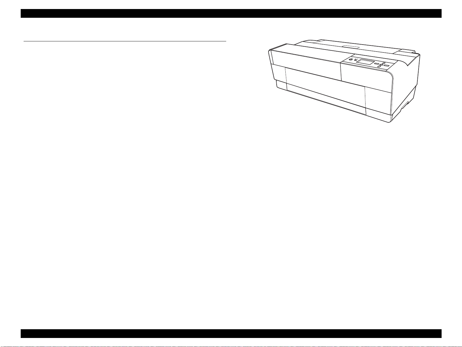
1.1 Product Description
Epson Stylus Pro 38 00/3800C/ 3850/3880/ 3885/389 0 are large s ize color in kjet print ers
that support up to A2 (17”) sized cut-sheet paper.
F-Mach (180N x 8-column) print head
Maximum print resolution (dpi): 2880 x 1440, Minimum dot: 3.5pl MSDT
Superior color and monochrome reproducibility with eight colors
HCD2 + K3 ink system, consisting of 4 basic colors (YMCK) with 2
complementary colors and 2 complementary blacks
80ml-size (injection volume) new ink cartridge
Automatic switching between black ink modes; Photo black and Matte black.
Requires no user intervention, and ink used during the conversion is remarkably
reduced.
Two manual paper feeders are provided in addition to the ASF (Auto Sheet
Feeder)
Rear manual feeder: FA paper
Front manual feeder: Board paper (up to 1.5 mm thickness)
Figure 1-1. External View
High speed network and communication supported
100BASE-TX/10BASE-T Network Interface
USB 2.0 High Speed Interface
Borderless printing support ed
Clearly arranged buttons and a large LCD offer quick, easy operation
PRODUCT DESCRIPTION Product Description 10
SE Group Confidential (Related Staff Only)
Page 11
Epson Stylus Pro 3800/3800C/3850/3880/3885/3890 Revision D
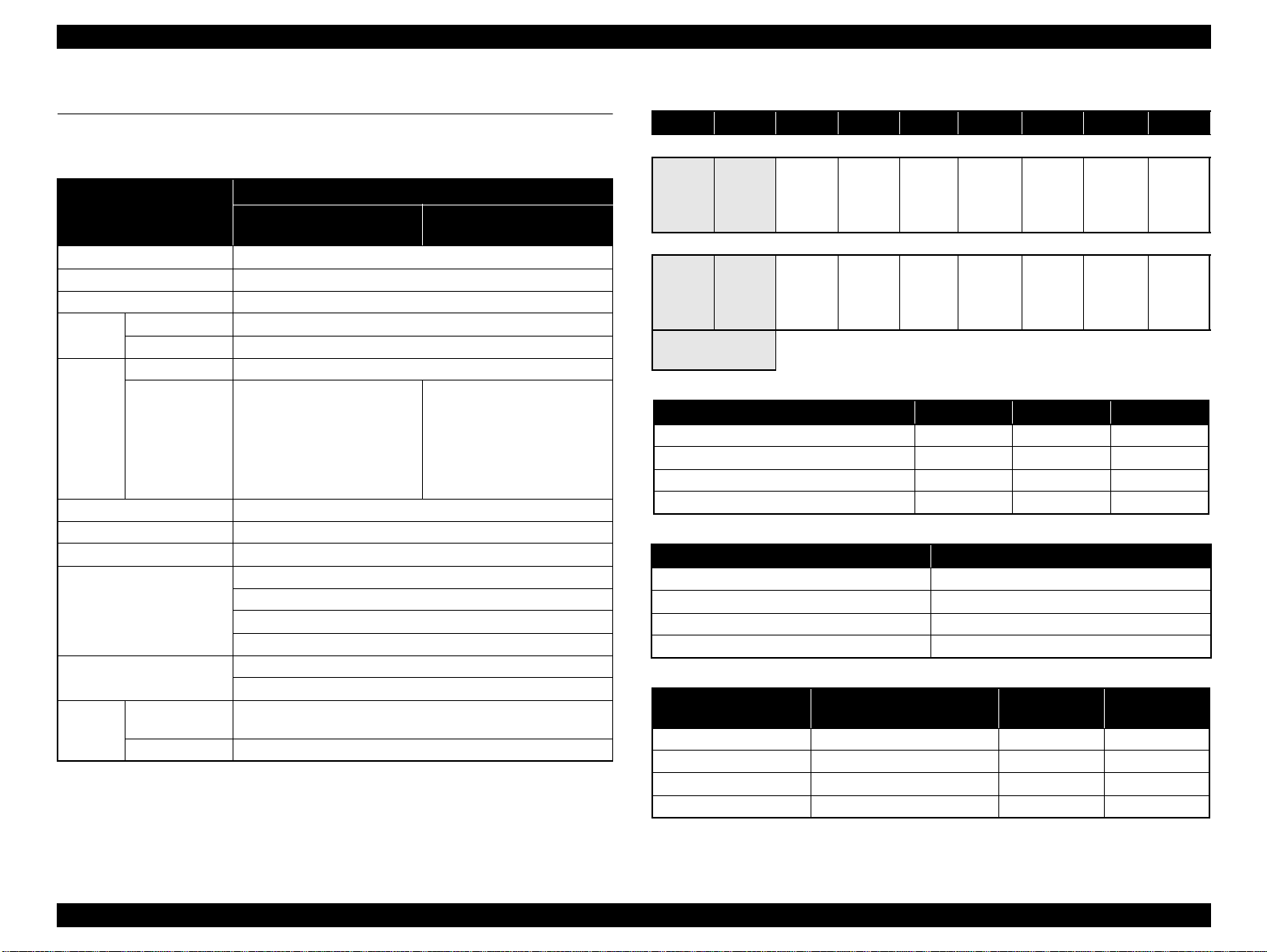
1.2 Basic Specifications
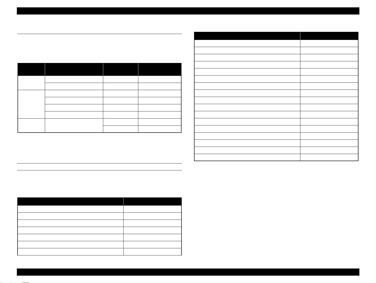
1.2.1 Basic Specifications
Specifications
Item
Maximum paper width 17 inch (43 cm)
Printing method On-demand ink jet m et hod
Printing directio n Two-way shortest distance printing with log ical seeking
Print Head
Ink
Maximum print resolution 2880 dpi x 1440 dpi
Smallest dot size 3.5 picoliters
Dot size Refer to Table 1-2
Printing function
Automatic adjustment function
Printing
speed/area
Note *: The all 9 ink cartridges can be installed simultaneously. The printer automatically switches
Type F-Mach
Number of nozzles 180 Nozzles per color (180 Nozzles x 8 colors)*
Type HCD2 + K3 (9 independent ink c artridges)*
Color of inks
Alphanumeric
characters
Graphic mode Refer to Table 1-4
between Photo and Matte bla c k depending on the driver selectio n w hil e uti li zing the same
physical ink channel.
Epson Stylus Pro 3800/
3800C/3850
Matte Black*, Photo Black*, Light
Black, Light Light Black, Cyan,
Magenta, Yellow, Light Cyan,
Light Magenta
(Refer to Table 1-1 for the
alignment sequence of the
cartridges)
Borderless printing
Silent paper feeding
Automatic bottom processing
L/4 x 6 Photo high-speed printing
Auto nozzle check
Auto Bi-d adjustment
Refer to Table 1-3
Epson Stylus Pro 3880/3885/
3890
Matte Black*, Photo Black*, Light
Black, Light Light Bl ack, Cyan,
Vivid Magenta, Yellow, Light
Cyan, Vivid Light Magenta
(Refer to Table 1-1 for the
alignment sequence of the
cartridges)
Table 1-1. Cartridge Alignment Sequence
Row 1 Row 2 Row 3 Row 4 Row 5 Row 6 Row 7 Row 8 Row 9
Epson Stylus Pro 3800/3 80 0C /3850
Matte
Black
(MK)
Photo
Black
(PK)
Light
Black
(LK)
Light
Light
Black
(LLK)
Cyan
(C)
Magenta
(M)
Light
Cyan
(Lc)
Light
Magenta
(Lm)
Yellow
(Y)
Epson Stylus Pro 3880/3 885/3890
Matte
Black
(MK)
Photo
Black
(PK)
Light
Black
(LK)
Light
Light
Black
(LLK)
Cyan
(C)
Vivid
Magenta
(VM)
Light
Cyan
(Lc)
Vivid
Light
Magenta
(VLM)
Yellow
(Y)
Switched by an Ink
Selector
Table 1-2. Dot Size
Dot Size L (pl) M (pl) S (pl)
VSD1 22.2 13.8 6.6
VSD2 13.2 5.9 3.5
VSD3 -- -- 3.5
Economy 22.2 -- --
Table 1-3. Printing Speed and Area (Alphanumeric Characters)
Item Specifications
Character quality
Fine
Character pitch 10 CPI
Printing area 167 digits
Printing speed
280 cps
Table 1-4. Printing Speed and Area (Graphic Mode)
Horizontal Resolution
(dpi)
360 441.8 mm (17.39 inch) 6,262 280 cps
720 441.8 mm (17.39 inch) 12,524 28 0 cps
1440 441.8 mm (17.39 inch) 25,047 280 cps
2880 441.8 mm (17.39 inch) 50,094 280 cps
Note *: Includes margins that bleed off the edges of paper. (max. 5 mm for both home and the opposite
sides.)
Maximum Printing Area*Printable Dots Printing Speed
PRODUCT DESCRIPTION Basic Specifications 11
SE Group Confidential (Related Staff Only)
Page 12
Epson Stylus Pro 3800/3800C/3850/3880/3885/3890 Revision D
Temperature (°C)
Humidity (%)
The printer
allowable rang e
Normal
ambient
environment
1.2.2 Electric Specifications
Item
100/120V Model 220/240V Model
Rated voltage 100 to 120 VAC 220 to 240 VAC
Input voltage ran ge 90 to 132 VAC 198 to 264 VAC
Rated frequency 50 to 60Hz
Input frequency range 49.5 to 60.5Hz
Rated current 0.6 A 0.3 A
Operating Approx. 25 W Approx. 25 W
Power
consumption
Low-power mode
*
Approx. 5 W Approx. 5.5 W
S/W turned OFF Approx. 0.3 W Approx. 0.4 W
Insulation resistance
Dielectric strength
10 MΩ or more
(between AC line and chassis at 500 VDC)
1.0 kVrms AC for 1 min. or 1.2 kVrms AC for 1 sec.
(between AC line and chassis)
Leak current 0.25 mA or less
Conforms to International Energy Star Program
Compliance with regulations
Note *: Shifting to low-power mode takes 15 min.
(Category: conforms to the harmonic restraint measure
guideline)
Conforms to VCCI Class B
Specification
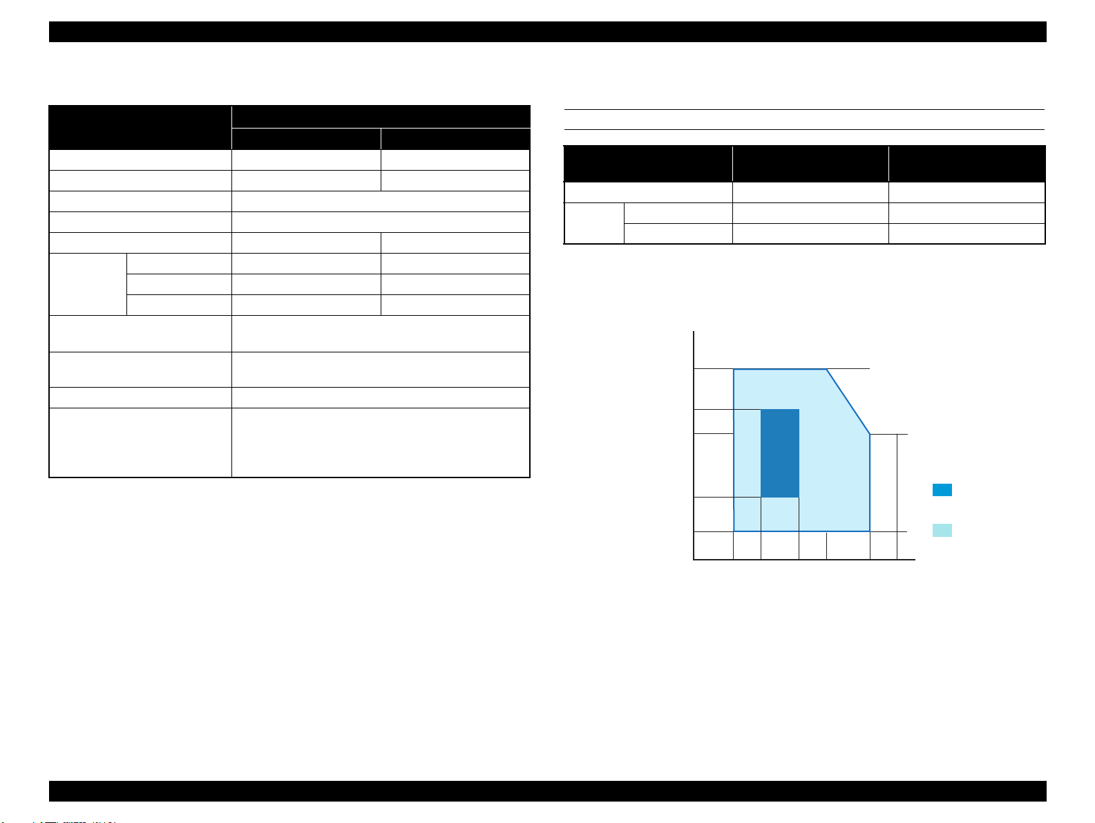
1.2.3 Environmental Characteristics
TEMPERATURE/HUMIDITY
Condition Temperature
*2
Operating 10 to 35 °C 20 to 80 %
before unpacki ng -20 to 60 °C*
Storage*
Note "*1": Includes condition during transportation.
1
after unpacking -20 to 40 °C*
"*2": The combined temperature and humidity conditions must be within the blue -sha ded range
shown in Figure 1-2.
"*3": Within 1 month under 40°C, within 120 hours under 60°C.
80
3
3
32
60
55
Humidity*2
(non condensation)
5 to 85 %
5 to 85 %
20
25
27
10 15
35 40
Figure 1-2. Temperat ure/Humidity Range
PRODUCT DESCRIPTION Basic Specifications 12
SE Group Confidential (Related Staff Only)
Page 13
Epson Stylus Pro 3800/3800C/3850/3880/3885/3890 Revision D
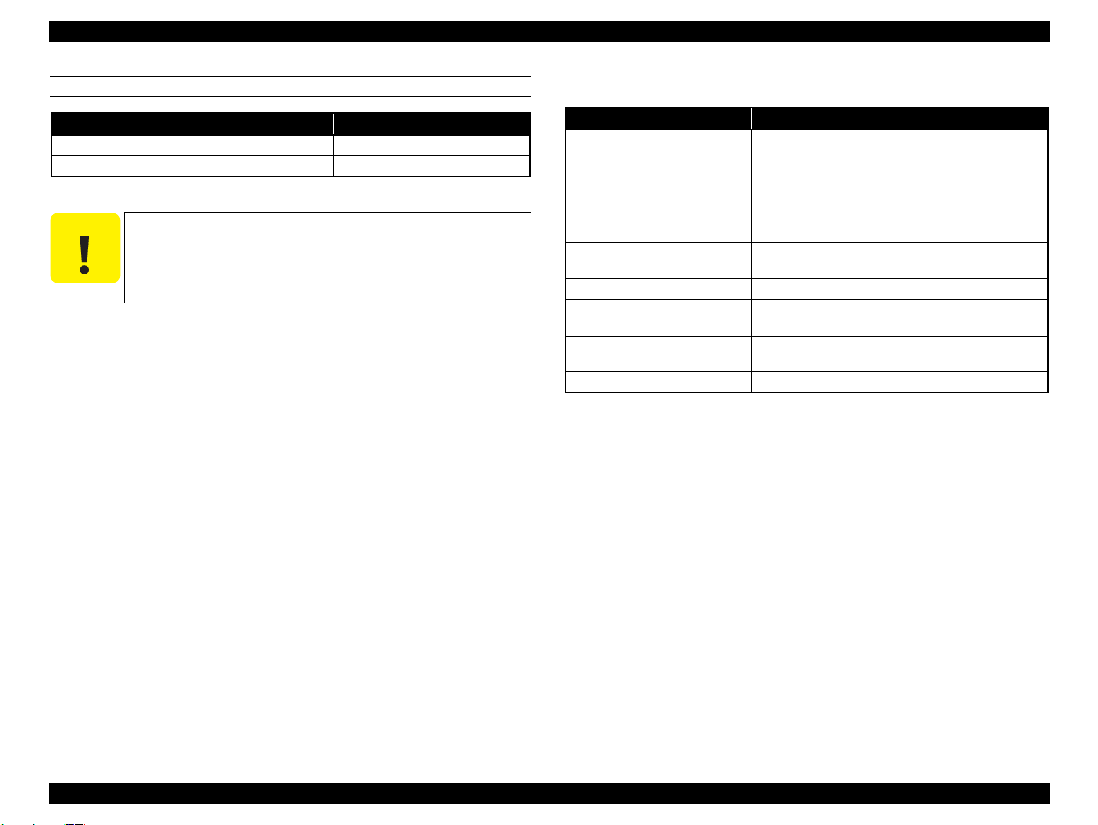
C A U T I O N
RESISTANCE TO VIBRATION/SHOCK
Vibration Shock
Operating 0.15G, 10 to 55Hz 1G, within 1ms
Storage 0.50G, 10 to 55Hz 2G, within 2ms
When transporting the printer, the print head must be capped,
and the ink cartridges must be removed.
If the print head is not capped with the power turned off, turn
the printer on with the ink cartridges installed, then turn it off
after confirming the print head is capped.
1.2.4 Reliability/Durability
Item Target
Until any one of the following conditions is met.
Operating life of the printer
MPBF
MTBF
Battery life 5 to 10 years
Extension of normal TCL
generation time
Simultaneous use of CL timer T1
and FL timer Tf
Periodical flu shing Every 1 hour
Note "*1": A4-sized paper, ECMA Pattern printing
"*2": Approx. 5% coverage
"*3": Total print time of 850 hours in normal ambient tem perature, approx. 10% coverage.
(POH = Power on hours)
• 12,000 pages (A2 plain paper fine mode)
• 1,600,000 paths (carriage movement)
•5 years
Black: 300 pages or more
Color: 150 pages or more
20,000 POH
(No faults with electronic parts and fans)
4,320 hours (6 months) printing time wi thin 2 hours
360 hours (15 da ys) printing time ov er 2 hours
Execution
*3
*1
*2
PRODUCT DESCRIPTION Basic Specifications 13
SE Group Confidential (Related Staff Only)
Page 14
Epson Stylus Pro 3800/3800C/3850/3880/3885/3890 Revision D
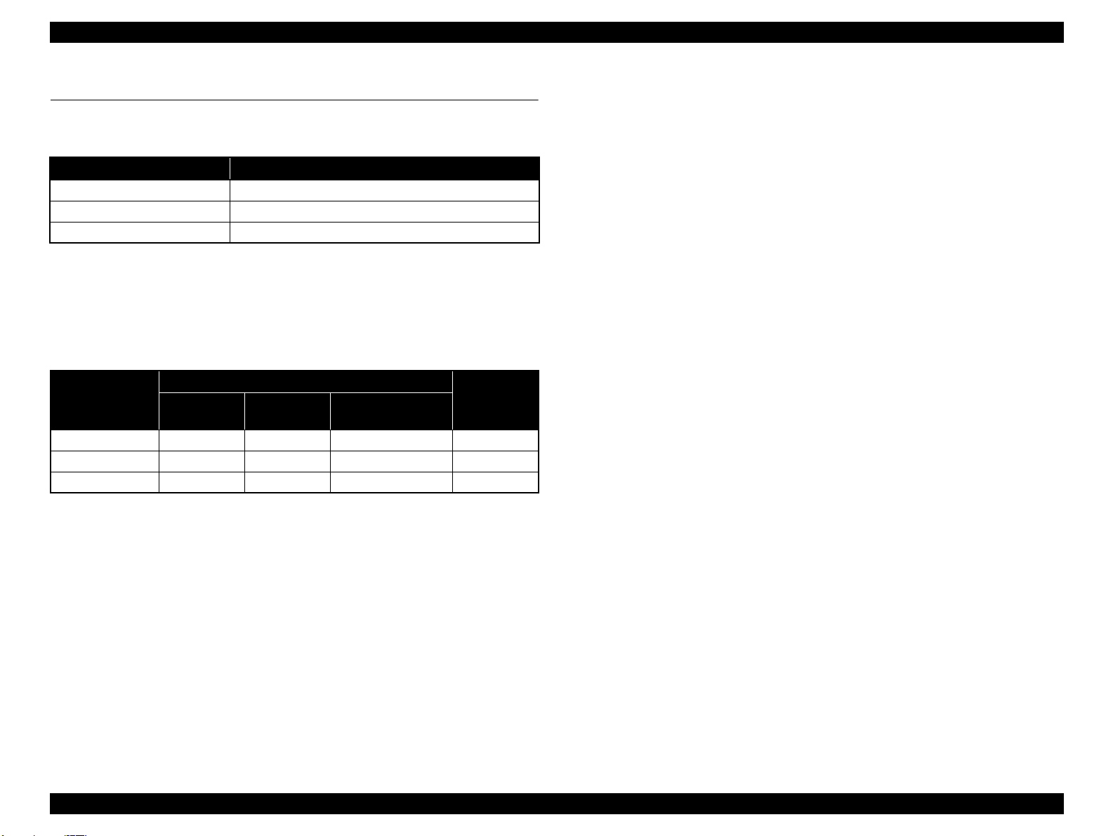
1.3 Printing Specifications
1.3.1 Paper Feed Specifications
Item Specification
Paper feed method Friction feed
Minimum pitch of paper feed 2.94 μm (1/8640 inch)
Paper feed speed 25.4 mm (1 inch) when line feed: 333 msec (3 inch/sec)
1.3.2 Paper Feeder Specifications
Epson Stylus Pro 3800/3800C/3850/3880/3885/3890 support three types of paper
feeding methods; ASF, Rear Manual Feed, and Front Manual Feed. The paper size and
thickness for each of the methods are shown in the table below. For paper type and
feeder capacity, refer to "1.3.3 Paper Support" (p15).
Paper Feed
Method
ASF 89 to 431.8 127 to 950 L/4”x6” to A2/USC 0.08 to 0.27
Rear Manual Feed 210 to 431.8 27 9 .4 to 95 0 A4/LTR to A2/USC 0.29 to 0.5
Front Manual Feed 210 to 420 279.4 to 594 A4/LTR to A2 1.2 to 1.5
Width (mm) Length (mm)
Paper Size
Standard paper
(mm)
Thickness
(mm)
PRODUCT DESCRIPTION Printing Specifications 14
SE Group Confidential (Related Staff Only)
Page 15
Epson Stylus Pro 3800/3800C/3850/3880/3885/3890 Revision D
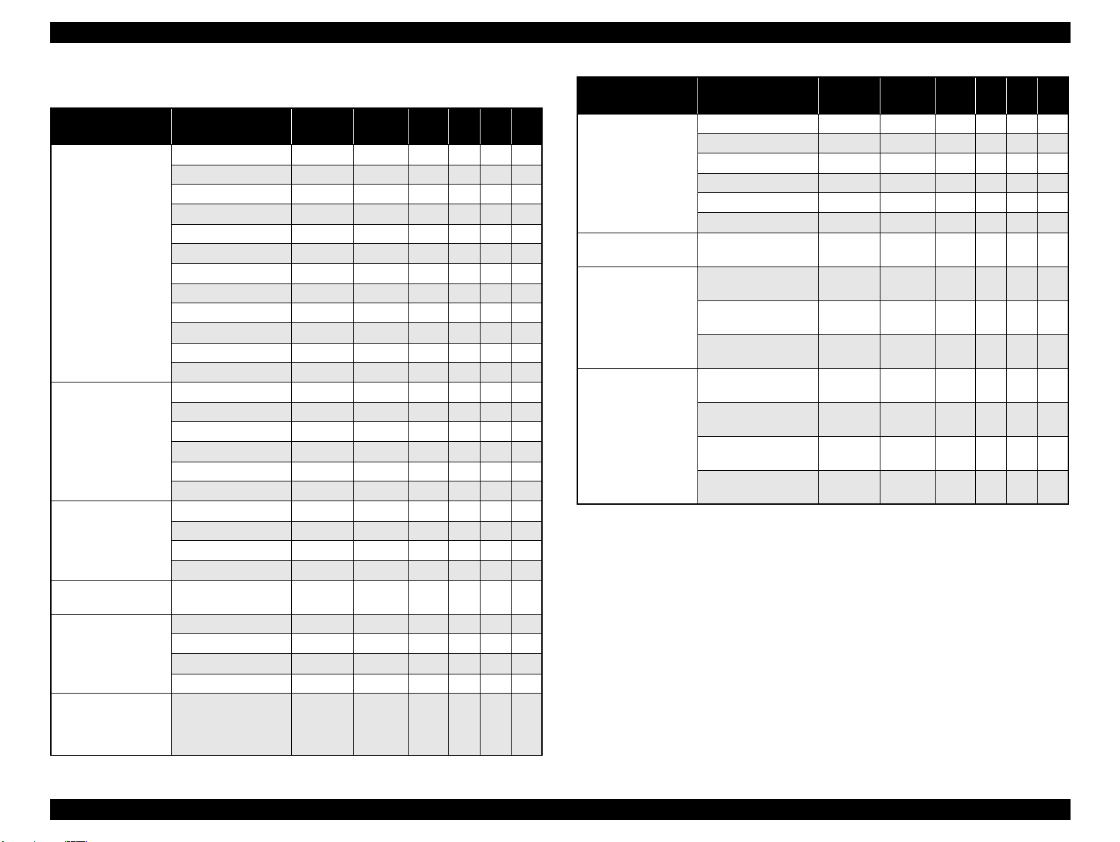
1.3.3 Paper Support
Media Name Size (mm)
L (3R) (89 x 127) ASF (20) √ P √
5” x 7” (127 x 178) ASF (20 ) √ P √ √
16:9 wide (102 x 148) ASF (20) √ P √√√
8” x 10” (203 x 254) ASF (20) √ P √
4” x 6” (102 x 152) ASF (20) √ P √√√
Premium Glossy Photo
Paper
Premium Semigloss
Photo Paper
Premium Luster Photo
Paper
Singleweight Matte
Paper
Photo Quality Ink Jet
Paper
(KANZAN for EU A4
only, ESF for others)
Proofing Paper
Semimatte
(Commercial
Semimatte)
11” x 14” (279 x 356) ASF (10) √ P √
Letter (216 x 279) ASF (20) √ P √
A4 (210 x 297) ASF (20) √ P √ √
A3 (297 x 420) ASF (10 ) √ P √√√
S-B/A3+ (329 x 483) ASF (10) √ P √ √ √
A2 (420 x 594) ASF (1) √ P √√
USC (432 x 559) ASF (1) √ P √
4” x 6” (102 x 152) ASF (20) √ P √√
Letter (216 x 279) ASF (20) √ P √
A4 (210 x 297) ASF (20 ) √ P √√
A3 (297 x 420) ASF (10) √ P √ √ √
S-B/A3+ (329 x 483) ASF (10) √ P √√√
A2 (420 x 594) ASF (1) √ P √ √
Letter (216 x 279) ASF (20) √ P √
A3 (297 x 420) ASF (10) √ P √
S-B/A3+ (329 x 483) ASF (10) √ P √
USC (432 x 559) ASF (1) √ P √ √ √
S-B/A3+ (329 x 483) ASF (50) NA M √√√
A4 (210 x 297) ASF (100) NA P/M √ √
Letter (216 x 279) ASF (100) NA P/M √
Legal (216 x 35 8) ASF (50 ) NA P/M √ √ √
USB (279 x 432) ASF (50) NA P/M √
S-B/A3+ (329x483) ASF (1) NA P √ √ √
Feeder
(capacity*1)
Borderless
2
print*
Black
Ink*
3
EAI EU Asia
Media Name Size (mm)
Letter (216x279) ASF (20 ) √ M √
Enhanced Matte Paper
(EAI)/Archival Matte
Paper
(EU, Asia)
Watercolor PaperRadiant White
UltraSmo oth Fine Art
Paper
Velvet Fine Art Paper
Note "*1": ASF = Auto Sheet Feeder
R.Manual = Rear Manual Feed
Front Manual Feed supports thicker paper (1.2 to 1.5mm thickness).
Paper loading capacit y for both Rear and Front Manual Feed is on e sheet.
"*2": User-defined size d pa per (89 x 127mm to 432 x 950mm) is not av ai la bl e for borderless
printing.
"*3": Shows the supported bl ack ink type
P: Photo Black
M: Matte Black
P/M: Both Photo and Matte Black are supported
A4 (210x297) ASF (20) √ M √ √
A3 (297x420) ASF (10) √ M √√√
S-B/A3+ (329x483) ASF (10) √ M √ √ √
A2 (420x594) ASF (1) √ M √√
USC (432x559) ASF (1) √ M √
S-B/A3+ (329x483)
A3+ (329x483)
A2 (420x594)
USC (432x559)
Letter (216x279)
S-B/A3+ (329x483)
A2 (420x594)
USC (432x559)
Feeder
(capacity*1)
R.Manual
R.Manual
R.Manual
R.Manual
R.Manual
R.Manual
R.Manual
R.Manual
(1)
(1)
(1)
(1)
(1)
(1)
(1)
(1)
Borderless
print*
Black
2
√ M √√
√ M √ √ √
√ M √√
√ M √
√ M √
√ M √ √ √
√ M √√
√ M √
Ink*
3
EAI EU Asia
PRODUCT DESCRIPTION Printing Specifications 15
SE Group Confidential (Related Staff Only)
Page 16

Epson Stylus Pro 3800/3800C/3850/3880/3885/3890 Revision D
PW
LM RM
TM
BM
PL
Printable Area
Paper Feed Direction
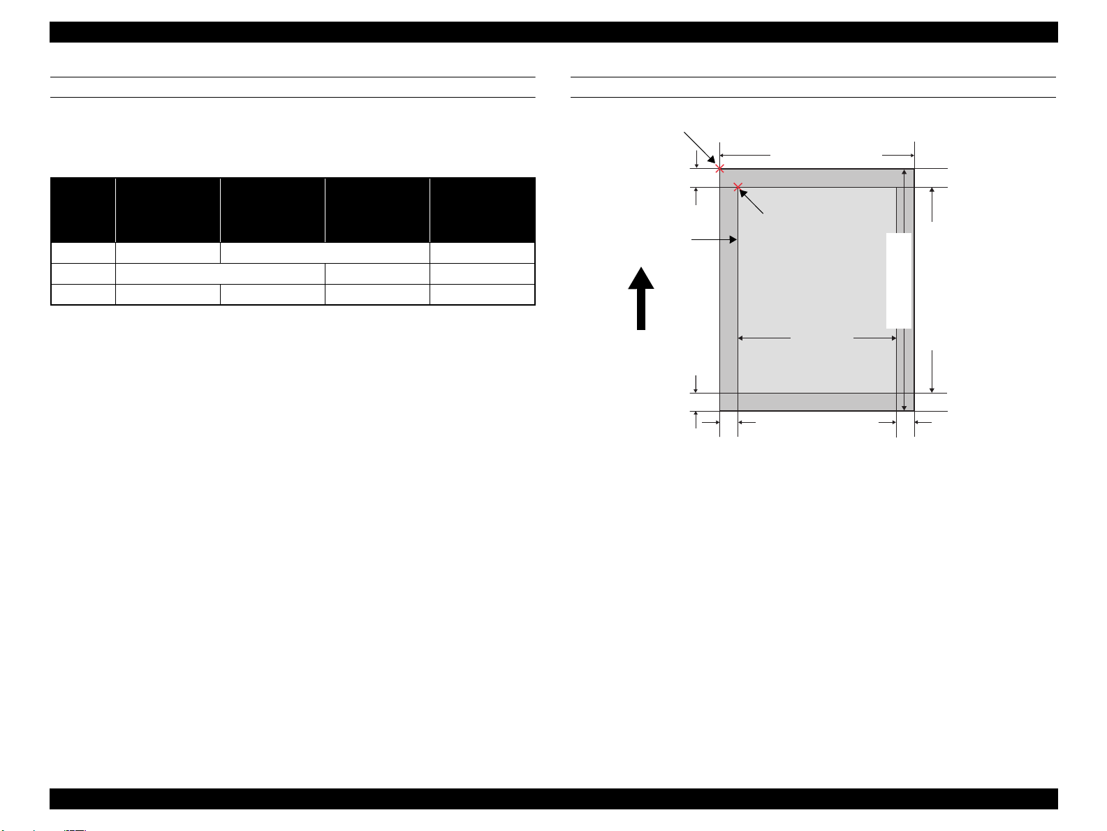
1.3.4 Printable Area
Item Dimension
PW (paper width) 89mm to 431.8mm
PL (paper length) 127mm to 950mm
TM (top margin) 0mm/3mm/20mm*
BM (bottom margin) 0mm/3mm/20mm*
LM (left margin) 0mm/3mm
RM (right margin) 0mm/3mm
Note *: TM and BM are fixed to 20 mm in front manual feeding.
The printer detects the paper width wh en paper is s et. (If th e paper width detection
setting is OFF, the printer does not detect the paper width.)
The printer does not print the image exceeding the detected paper width and the
printable area that is specified in the paper setting. (If the paper width detection
setting is OFF, the printer may print on the platen.)
The top/bottom/left/right margins (TM, BM, LM, RM) can be set to zero under
special conditions.
Because the printer detects tilt of loaded paper in a range of 3 mm at both left and
right sides, an image bleeds off both left and right edges of paper by 3 mm each at
borderless printing. However, if the distance between the paper edges and the
platen (sponge width) is less than 3 mm, the bleeding margins are adjusted to less
than 3 mm (within the range of 0 mm
(Refer to "1.4.2 Borderless Printing" (p17), for the borderless print specification.)
∼
3 mm) not to directly print on the platen.
Figure 1-3. Printable Area
PRODUCT DESCRIPTION Printing Specifications 16
SE Group Confidential (Related Staff Only)
Page 17
Epson Stylus Pro 3800/3800C/3850/3880/3885/3890 Revision D
1.4 Print Mode
This section provides specifications of the print mode and borderless printing.
1.4.1 Print Mode
Media Type Print Quality
Plain Paper
Inkjet Paper
-- ISV Square Resolution Mode
Note "*1": Driver not supported
"*2": Driver not supported (supports Out_bit_1 only)
Draft 360 x 360 dpi VSD1_Eco (280cps)
Normal (360 dpi) 720 x 360 dpi VSD1 (280cps)
Normal (360 dpi) 720 x 360 dpi VSD1 (280cps)
Fine (720 dpi) 720 x 720 dpi VSD1 (280cps)
Super Fine (1440 dpi) 1440 x 720 dpi VSD2 (280cps)
Super Photo (2880 dpi) 2880 x 1440 dpi VSD3 (280cps)
1.4.2 Borderless Printing
AVAILABLE PAPER SIZE
The following table l ists pape r sizes in the order s hown by t he printer d river, and s hows
the borderless printing availability.
Print Density
(H x V)
1440 x 1440 dpi VSD2 (280cps)
2880 x 2880 dpi VSD3 (280cps)
Dot Size
*1
*2
Table 1-5. Borderless Printing Available Paper Sizes
Paper Size Displayed by Driver Borderless Print
A4 (210 x 297 mm) Available
A3 (297 x 420 mm) Available
Super A3 (329 x 483 mm) Available
A2 (420 x 594 mm) Available
B5 (182 x 257 mm) NA
B4 (257 x 364 mm) NA
B3 (364 x 514 mm) NA
89 x 127 mm (3.5 x 5 in) Available
102 x 152 mm (4 x 6 in) Available
127 x 178 mm (5 x 7 in) Available
16:9 wide (102 x 181 mm) Available
203 x 254 mm (8 x 10 in) Available
254 x 305 mm (10 x 12 in ) Available
279 x 356 mm (11 x 14 in ) Available
305 x 305 mm (12 x 12 in ) NA
406 x 508 mm (16 x 20 in ) Available
User Defined* NA
Note *: The minimum user defined size is 3.5 x 5 in (89 x 127 mm), and the maximum size is 17 x 37.4
in (432 x 950 mm).
Table 1-5. Borderless Printing Available Paper Sizes
Paper Size Displayed by Driver Borderless Print
Letter (8 2/1 x 11 in) Available
Legal (8 2/1 x 14 in) NA
Half Letter (5 2/1 x 8 2/1 in) NA
US B (11 x 17 in) Available
US C (17 x 22 in) Available
A6 (105 x 148 mm) NA
A5 (148 x 210 mm) NA
PRODUCT DESCRIPTION Print Mode 17
SE Group Confidential (Related Staff Only)
Page 18
Epson Stylus Pro 3800/3800C/3850/3880/3885/3890 Revision D
3.5m (max)
5mm (max)
5mm
(max)
Width-direction
printable area
Printable area
Paper width
Page control
coordinate origin
Printing position coordinate origin
Paper edge
Paper
feeding
direction
5mm
(max)
Length-direction
printable area
Bottom position
AUTOMATIC EXPANSION SPECIFICATION
The driver automatically changes margins that bleed off the edges of paper according
to the paper size.
Table 1-6. Borderless Printing Margins (Bleed)
16:9 Wide
L/4” x 6”
5” x 7”
8” x 10”
A4 / Letter
Top 1.34mm (19dot) 2.96mm (42dot) 3.32mm (47dot)
Left/Right 2.54mm (36dot) 3.46mm (49dot) 4.52mm (64dot)
Bottom 2.54mm (36dot) 4.02mm (57dot) 4.52mm (64dot) 5.01mm (71dot)
Note : The number of dots are based on 360 dpi.
11” x 14”
A3/A3+
A2/USC
PRINTABLE AREA
Figure 1-4. Printable Area
Note : Print start position can be shifted toward the hom e position by 8 m by changing the appropriate
setting.
PRODUCT DESCRIPTION Print Mode 18
SE Group Confidential (Related Staff Only)
Page 19
Epson Stylus Pro 3800/3800C/3850/3880/3885/3890 Revision D
257 mm
550 mm
684 mm
90 mm
293 mm
376 mm
1040 mm
100 mm
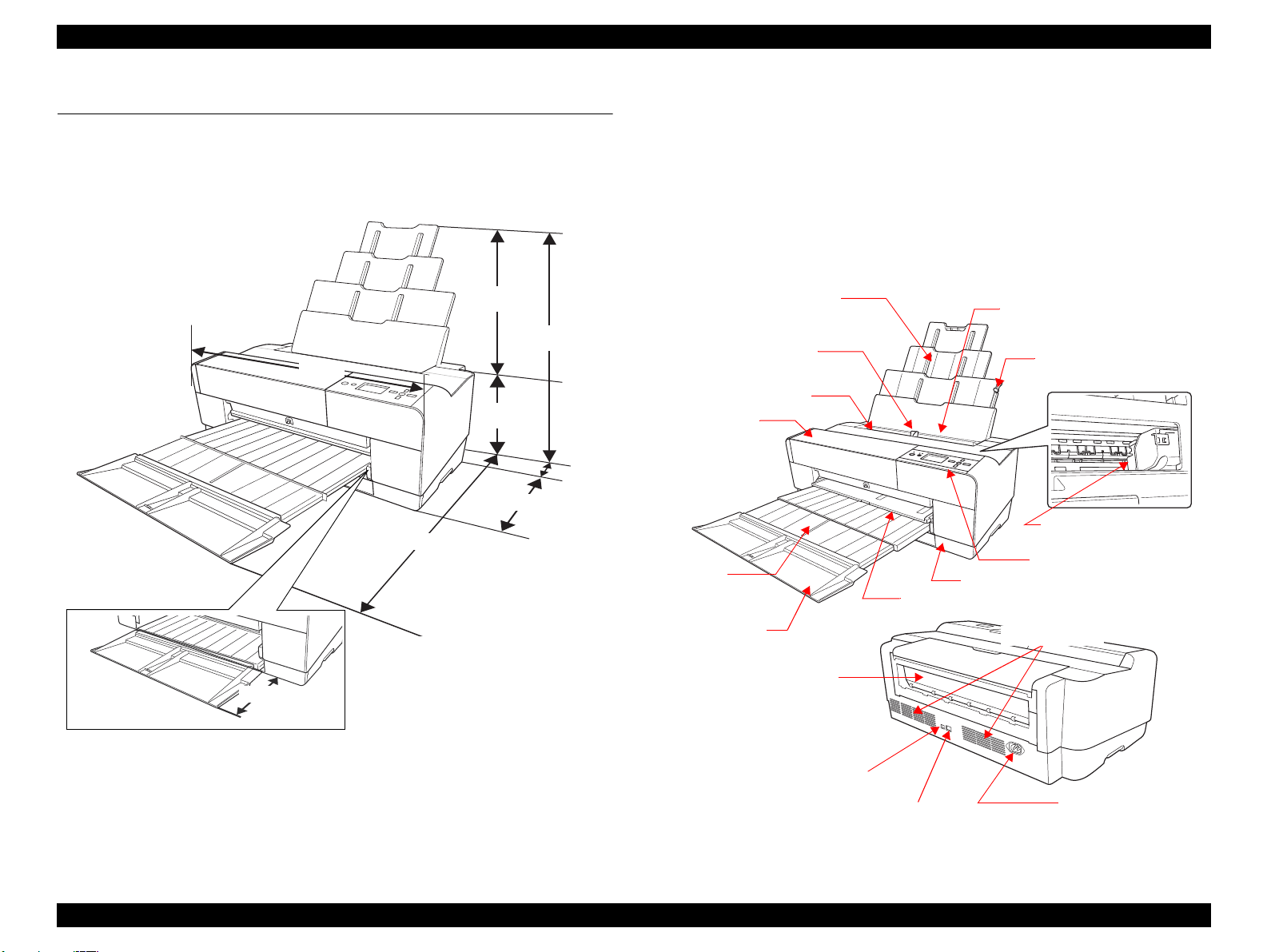
Maintenance Cartridge Cover
Paper Support
AC Connector
USB Interface Connector
Network Interface Connector
Edge Guide
Auto Sheet Feeder
Paper Support Edge
Guide
Top Cover
Ink Cover
Board Paper Tray
Paper Eject
Tray Cover
Paper Eject
Tray
Operation Panel
Print Head (Nozzl e)
Rear Paper
Feeder
Exhaust Outlet
1.5 Appearance Specifications
This section describes external dimensions and parts names.
1.5.1 Dimensions/Weight
Dimensions
Storage: 684 (W) x 376 (H) x 257 (D) mm
Printing: 684 (W) x 1040 (H) x 550 (D) mm
Weight
18.5 kg (excluding ink cartridges, including Maintenance cartridge)
19.8 kg (including ink cartridges)
1.5.2 Part Names
Figure 1-5. External Dimensions
Figure 1-6. Parts Names
PRODUCT DESCRIPTION Appearance Specifications 19
SE Group Confidential (Related Staff Only)
Page 20
Epson Stylus Pro 3800/3800C/3850/3880/3885/3890 Revision D
3
4 6
7
B
A
1
2
5
Back/Left
Ink Cover Open/Up
Power
Cancel/Reset
Enter
Paper Feed/Down
Menu/Right
Power LED
Paper status LED
Ink status LED
C
ABC
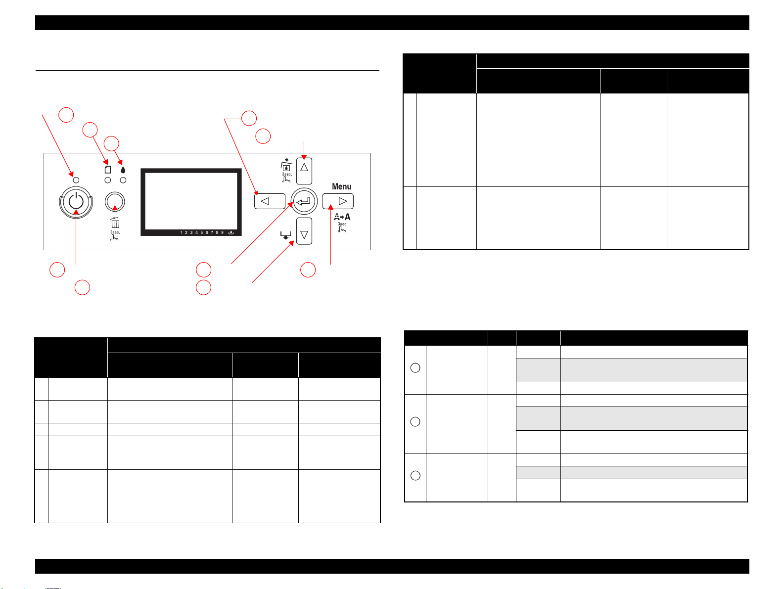
1.6 Operation Panel
1.6.1 Buttons and Functions
Figure 1-7. Operation Panel
1.6.2 Buttons
Functions
Button
1 Back/Left -- --
Ink Cover Open/
2
Up
3 Power Turns the power ON or OFF
4 Cancel/Reset
5 Enter -- --
*2
Normal One Pr es s
--
*1
• Clears error
• Opens I/H Cover
(When the printer runs out of ink)
Hold Down for
3 Seconds
Unlocks the Ink
Cover
-- Power OFF
Cancels the job Interrupts panel setting
Function at the
Panel Setting
Moves to the pr evious
menu item (Ascent)
Set Value +
• Accepts the change
of setting
• Executes the
selected operation
• Saves the s etting
Functions
Button
Paper Feed/
6
Down
6 Menu/Right
Note "*1": The printer is always turned OFF regardless of operation status.
"*2": When turning th e power ON while holding down th e Cancel button, the maintenance mode
becomes activated. (Re fer to
"*3": Deactivated during printing.
Normal One Press
• When paper is set
ASF: Ejects the paper
Manual-Rear: Backfeeds the paper
Manual-Front: Ejects the paper
• When paper is not set
ASF starts paper feeding
• When Manual-Front Tray Cover is
opened.
Manual-Front starts pap er fe eding
• During printing
Changes the panel display to the
Printer Status Menu
• When not printing
Shifts the printer into the Panel
Setting Mode
"1.6.7 Maintenance Mode" (p28)
Hold Down for
3 Seconds
-- Set Value -
Runs a head
*3
cleaning
for details.)
Function at the
Panel Setting
Moves to the ne xt
menu item (Descent)
1.6.3 LED
LED Color Displays Status
ON The power is ON.
Receiving data, during print ing , or executing power off
Power Green
Paper status Red
Ink status Red
*
Flashing
OFF The power is OFF.
ON Impossible to make a print due to the paper status.
Flashing
OFF
ON An ink-related error is occurring.
Flashing*An ink-related warnin g i s occurring.
OFF
sequence.
• A paper feeding or ejec ti ng e rror is occurring.
*
• A maintenance call error is oc cu rring.
The papers are in normal condition without an error or
warning.
The inks are in normal condi ti on without an error or
warning.
PRODUCT DESCRIPTION Operation Panel 20
SE Group Confidential (Related Staff Only)
Page 21

Epson Stylus Pro 3800/3800C/3850/3880/3885/3890 Revision D
2
4
1
5
6
3
12
3
2
3 4
1
Note *: Alternately turns On and Off every 500 ms. In the case of maintenance call error, they light for 100
ms at intervals of five seconds.
Note : When a service call error occurs, all the LE Ds fl ash.
1.6.4 Panel Display
Normal indication
Figure 1-8. Panel Display (Normal indication)
No. Item Description
1 Messages Printer status, operation status, and err or messages are displayed.
2 User-defined paper No.
Paper type
3
(For Cut-sh eet only)
4 Platen Gap
5 Ink Cartridge Status The rem a ini ng amount of ink in each cartridge is displayed.
Remaining
Maintenance Cartridge
6
Status
The user-defined paper setting number created by the CUSTOM
PAPER function in the panel setting menu is displaye d.
This icon is displayed when the number of paper, except STANDARD
paper, created by the CUSTOM PAPER function in the panel setting is
selected.
The platen gap setting ma de by the PLATEN GAP function in the
panel setting menu is indicated.
Free space of the Maintenance Cartridge is displayed.
Error indication
Figure 1-9. Panel Display (Error indication)
No. Item Description
1 Error name Error name is highlighted.
2 Error icon Error icon is displayed.
3 Remedy Describes the cause of error and gives instru ctions to clear the error.
Note : When multiple errors occur simu lt aneously, they are displayed in the order of precedence. The
next error indication appears when previous one is cleared.
Error indication (Displayed with an illustration)
Figure 1-10. Panel Display (Error indication: Displayed with an illustration)
No Item Description
1 Error name Error name is highlighted.
2 Error icon Error icon is displayed
3 Illustration
4 Remedy Describes th e caus e of the er ror and gives inst ruc ti ons to clea r th e erro r.
Note : When multiple errors occur simu lt aneously, they are displayed in the order of precedence. The
next error indication appears when previous one is cleared.
Describes the cause of t he error and gives instru ctions to clear the error
using a illustration.
PRODUCT DESCRIPTION Operation Panel 21
SE Group Confidential (Related Staff Only)
Page 22
Epson Stylus Pro 3800/3800C/3850/3880/3885/3890 Revision D
12 4 5678 91011
12
13
14
15
16 17 18 19 20
3
0
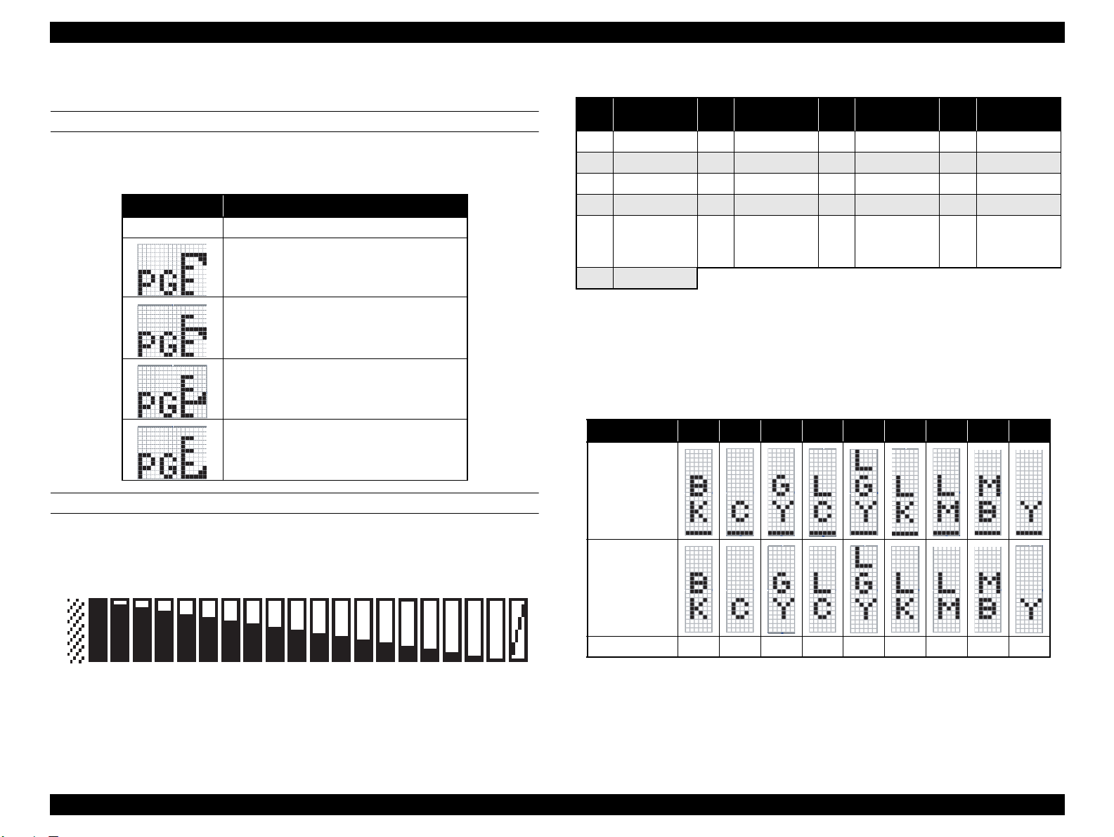
1.6.5 Icons on the LCD
PLATEN GAP SETTING
The platen gap specified in PRINTER SETUP and CUSTOM PAPER menus is
indicated with icons as shown below.
Icons Status
-- STANDARD is selected.
NARROW is selected.
WIDE is selected.
WIDER
is selected.
WIDEST is selected.
INK CARTRIDGE STATUS
Table 1-7. Relation between Counters and Remaining Ink
Remaining Ink
No.
0*1Not selected K 6 67-72 11 39-44 16 12-16
1 95-100 7 62-66 12 34-38 17 6-11
2 89-94 8 56-61 13 28-33 18 1-5
3 84-88 9 51-55 14 23-27 19
4 78-83 10 45-50 15 17-22 20
5 73-77
Note "*1": D i sp la ys ei th er Matte BK or Photo BK that is not in use when printi ng.
(%)
"*2": Counter No.19 is displayed when non-genuine ink ca rtridge(s) is used.
No.
Remaining Ink
(%)
No.
Remaining Ink
(%)
No.
*2
No cartridge is
set or an error
has occurred.
Remaining Ink
(%)
Ink Out
Ink Low/Ink Out Indicator
The indicators below is displayed when Ink becomes Low or Out.
Note : The following table is for Epson Stylus Pro 3800/3800C/3850. In the case of Epson Stylus Pro
3880/3885/3890, M is VM and LM is VLM.
No.
Icon
(Ink Low)
1 2 3 4 5 6 7 8 9
Ink Counter
The remaining amount of ink in each cartridge is indicated on the panel as shown
below.
Figure 1-11. Ink Counter
Icon
(Ink Out)
Colors PK C LK Lc LLK Lm M MK Y
PRODUCT DESCRIPTION Operation Panel 22
SE Group Confidential (Related Staff Only)
Page 23
Epson Stylus Pro 3800/3800C/3850/3880/3885/3890 Revision D
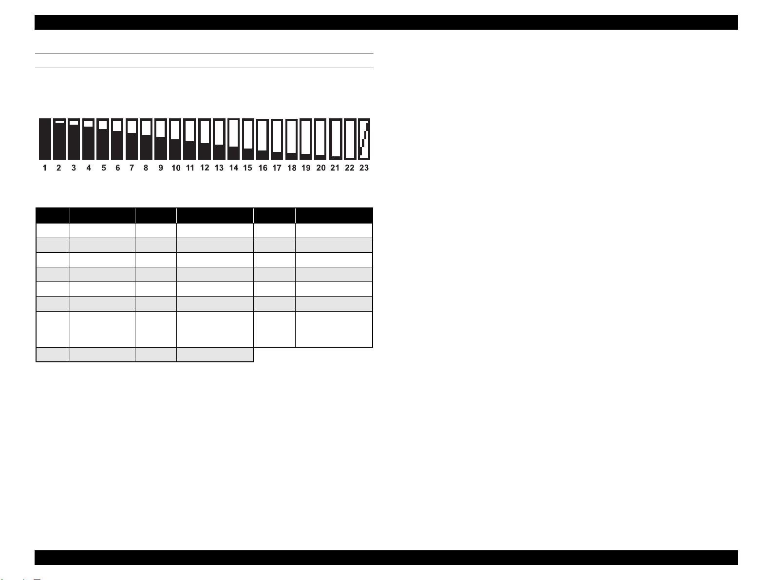
MAINTENANCE CARTRIDGE STATUS
Maintenance Cartridge Counter
The free space of the Maintenance Cartridge is indicated as shown below.
Figure 1-12. Maintenance Cartridge Status
Table 1-8. Relation between Counters and Remaining Ink
No. Free Space
1 96-100 9 58-61 17 20-23
2 91-95 10 53-57 18 15-19
3 86-90 11 48-52 19 10-14
4 81-85 12 43-47 20 5-9
5 77-80 13 39-42 21 1-4
6 72-76 14 34-38 22 0
7 67-71 15 29-33 23
8 62-66 16 24-28
(%)
No. Free Space
(%)
No. Free Space
No cartridge is set or
an error has
occurred.
(%)
PRODUCT DESCRIPTION Operation Panel 23
SE Group Confidential (Related Staff Only)
Page 24
Epson Stylus Pro 3800/3800C/3850/3880/3885/3890 Revision D
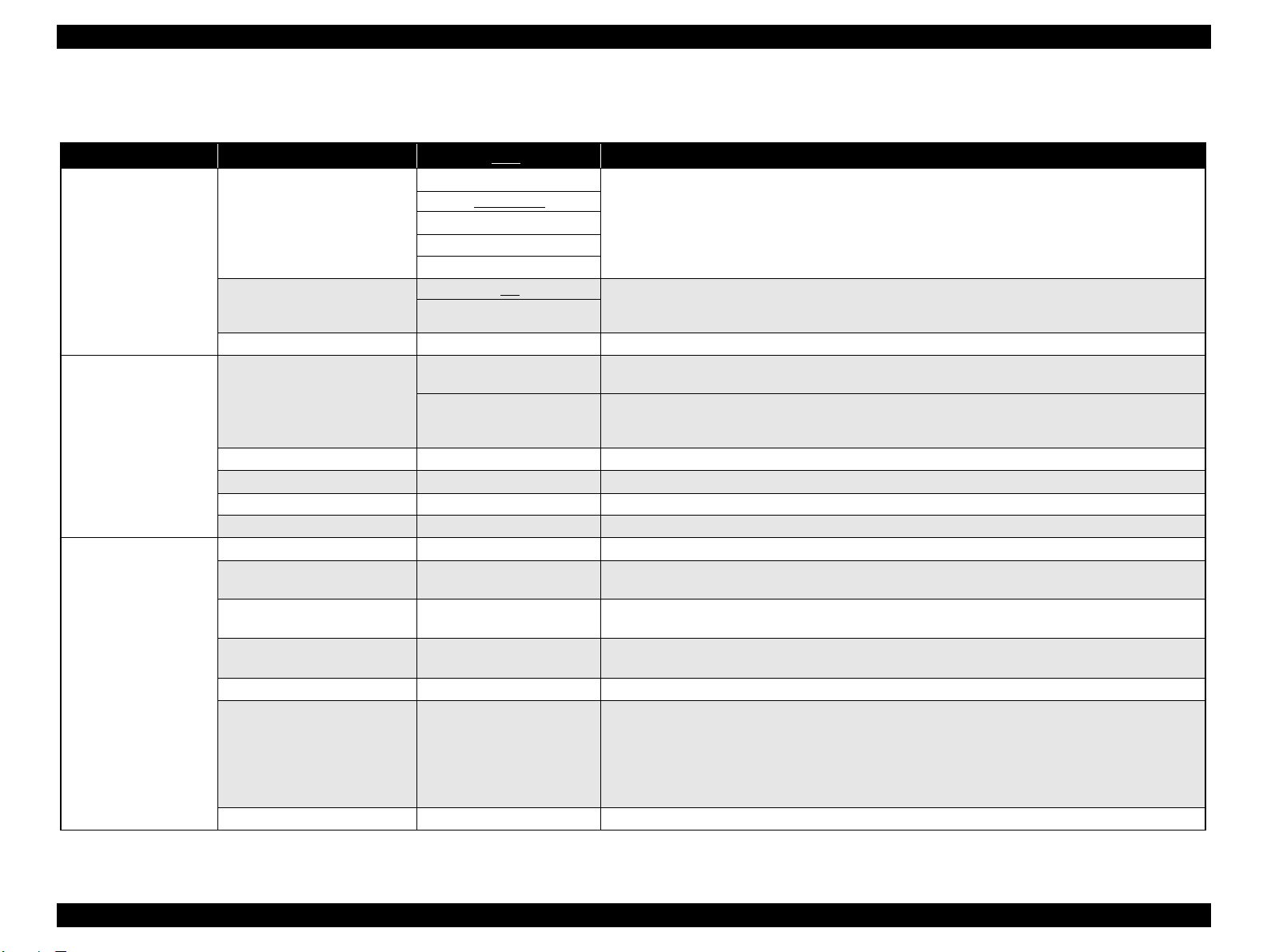
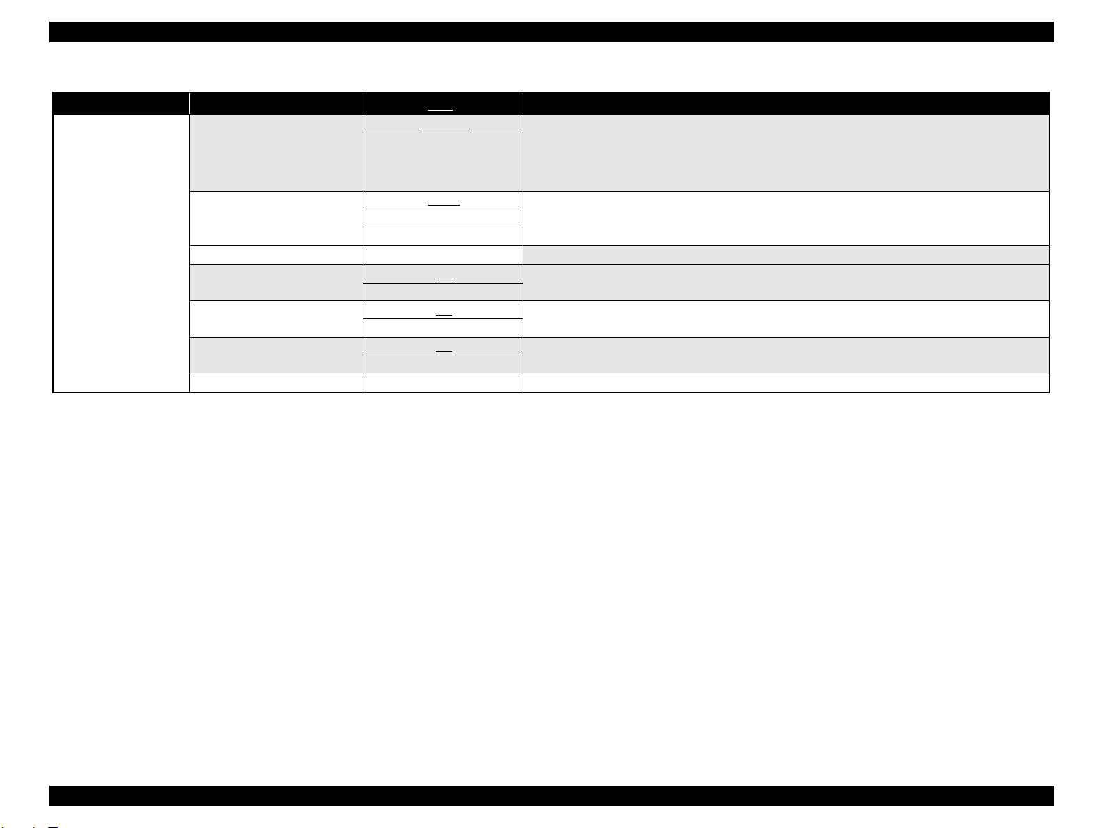
1.6.6 Menu Settings
Table 1-9. List of Menu Settings
Top Menu Menu Items Settings (Bold = default) Explanation
NARROW
PRINTER SETUP
TEST PRINT
PRINTER STATUS
STANDARD
PLATEN GAP
PAPER SIZE CHECK
INITIALIZE SETTINGS EXECUTE All settings made using the co ntrol panel ar e r eturned to the ir d efault.
NOZZLE CHECK
STATUS SHEET PRINT Prints information on the printer status.
NETWORK STATUS SHEET PRINT
JOB INFORMATION PRINT Pr ints inf orm at ion on print jobs stored in the printer up to 10 jobs.
CUSTOM PAPER PRINT Prints setting values set in the CUSTOM PAPER menu.
VERSION o0XXXX-XX.XX.ICBS Displays the firmware version installed on the printer. (see "Firmware version indication" (p27))
PRINTABLE PAGES
INK LEVEL
MAINTENANCE TANK
USAGE COUNT INK xxxxx.xml Displays ink amount consumed in ml units.
JOB HISTORY
TOTAL PRINTS nnnnnn PAGES Displays the gross number of printed pages in decimal up to six digits.
(MAINTENANCE TANK)
WIDE
WIDER
WIDEST
ON
OFF
MANUAL
AUTO
(Ink color)
nnnnnnn PAGES
(Ink color)
nn%
nn%
No.0 to No.9
INK xxxxx.xml
PAPER xxxx.x cm
2
Adjusts the gap between the print head and th e platen. The set value is returned to the default at every power-on.
When the PAPER TYPE in the CUSTOM PAPER menu is set to other than the default, the PLATEN GAP setting in
the menu takes priority over this setting. (see "PG settings list" (p27))
Setting to OFF deactivates the sensor that detects paper width when paper is loaded. This enables to print on paper
whose width is out of the sens or’s detectable range, however, the user should know that if he/she prin ts an image
larger than the paper size, the image extended off the edges of the paper is printed directly on the platen.
Prints a nozzle check pattern, firmware version, usage count of paper and ink, and free space in the maintenance
cartridge. Visually check the printed check pattern, and decide whether cleaning is required or no t.
Prints a nozzle check pattern, firmware version, usage count of paper and ink, and free space in the maintenance
cartridge. The ink mark sensor scans the printed check pattern and cleaning is automatically carried out if it is judged
necessary.
Prints information on the network status.
Displays the number of pa ges t hat can be printed with the installed ink cartridge.
Displays the percentage of ink level in each installed cartridge.
Displays the percentage of free space in the maintenance cartridge.
JOB NO.
Displays the job number assigned by the printer. The No.0 is the latest job.
INK LEVEL
Displays ink amount consum ed for each job.
PAPER SIZE
Displays the number of pages of ea ch job.
PRODUCT DESCRIPTION Operation Panel 24
SE Group Confidential (Related Staff Only)
Page 25
Epson Stylus Pro 3800/3800C/3850/3880/3885/3890 Revision D
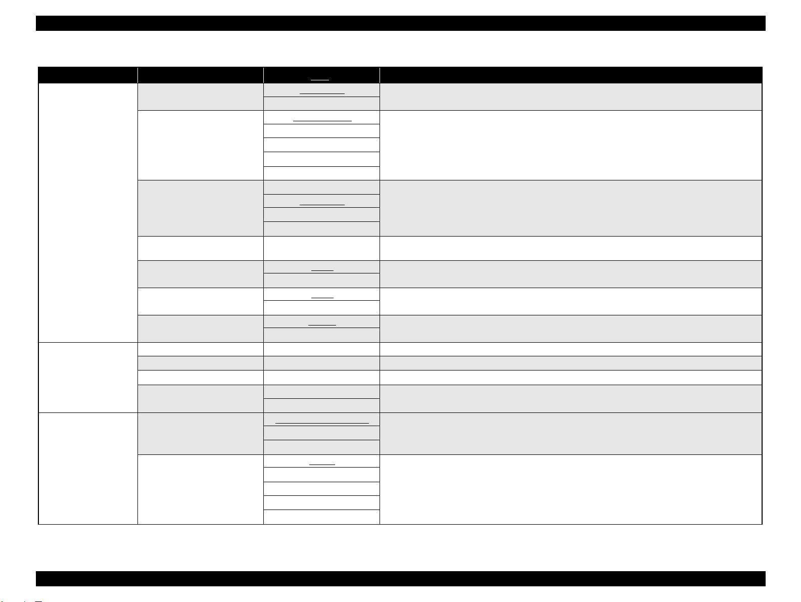
Table 1-9. List of Menu Settings
Top Menu Menu Items Settings (Bold = default) Explanation
CUSTOM PAPER
MAINTENANCE
HEAD ALIGNMENT
PAPER NUMBER (1-10)
PAPER TYPE
PLATEN GAP
THICKNESS PATTERN PRI NT
PAPER FEED ADJUST A
PAPER FEED ADJUST B
DRYING TIME
BLACK INK CHANGE EXECUTE Switches the black ink between Ma t te and Ph oto .
POWER CLEANING EXECUTE Performs a powe r cl eaning.
CLOCK SETTING YY/MM/DD HH:MM Sets date and time of th e internal clock.
CONTRAST ADJUSTMENT
AUTO
MANUAL
STANDARD
PAPER NO.1-10
MATTE THICK
MATTE THIN
PHOTO PLAIN
FINE ART PAPER
REMOTE PANEL PAPER
NARROW
STANDARD
WIDE
WIDER
0.00%
-0.7% to 0.7%
0.00%
-0.7% to 0.7%
0.0 SEC
0.0 SEC to 10.0 SEC
0
-20 - 0 - +20 (dec)
PREM.GLOSSY/LUSTER
PQ INK JET PAPER
ENHANCED MATTE PAPER
0.1 mm
0.2 mm
0.3 mm
0.4 mm
0.5 mm
Paper type and relating settings can be saved and easily retrieved by assigning a number to them. Up to 10 groups of
settings can be stored. When EPSON genuine paper is used, STANDARD should be selected.
Selects a paper type corresponds to the pape r.
Adjusts the p laten gap accor ding to the sele cted paper type .
Prints a pattern to detect the thickness of loaded paper. (When STANDARD is selected in the PAPER NUMBER,
this menu is not displayed.)
Sets paper feed amount for the printable area. The amount incre ases/decreases by the selected percentage of one
meter.
Sets paper feed amount for th e bottom area (out of the printabl e area). The amount increases/ de creases by the
selected percentage of one meter.
Sets a time period to stop the print head movem ent for drying ink.
Adjusts the contrast of the control pane l display.
Selects a paper type to be used for the gap adjustment.
Selects a gap to be adjusted manually.
PRODUCT DESCRIPTION Operation Panel 25
SE Group Confidential (Related Staff Only)
Page 26
Epson Stylus Pro 3800/3800C/3850/3880/3885/3890 Revision D
Table 1-9. List of Menu Settings
Top Menu Menu Items Settings (Bold = default) Explanation
NETWORK SETUP
NETWORK SETUP
IP ADDRESS SETTING
IP, SN, DG SETTING
APPLE TALK
MS NETWORK
BONJOUR
INIT NETWORK SETTING
DISABLE
ENABLE
AUTO
PANEL
PING
---
ON
OFF
ON
OFF
ON
OFF
EXECUTE
Disables or enables a network connection. The other NETWORK SETUP menu items appear only when ENABLE
has been selected. Under the following conditions, this setting is automatically changed to DISABLE.
• Every power-on (always returns to the default: DISABLE)
• When the network setup ini ti a li zation is performed.
• When the PANEL DEFA U LT in the maintenance mode is performed.
Select the settings for the IP address to use.
When [PANEL] is selected, the settings in [IP, SN, DG SETTING] are enabled.
Set the IP address, Subnet mask, and default gate w ay .
Enables (ON)/disables (OFF) AppleTalk.
Enables (ON)/disables (OFF) MS NETWORK.
Enables (ON)/disables (OFF) BONJOUR.
Returns the network I/F related settings to their default.
PRODUCT DESCRIPTION Operation Panel 26
SE Group Confidential (Related Staff Only)
Page 27
Epson Stylus Pro 3800/3800C/3850/3880/3885/3890 Revision D
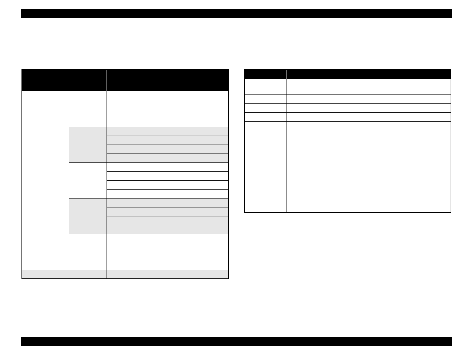
PG settings list
The table below lists the platen gap amounts settable with the printer driver, control
panel, and media table.
Table 1-10. PG Setting List
Printer Driver
Paper Thickness
setting
No setting
0.0 to 0.8mm
0.9mm to 1.5mm -- -- 3.5
Control Panel
Setting
NARROW
STANDARD
WIDE
WIDER
WIDEST
Media Table or
Printer Driver
PG Setting
Minimum 0.9
Small 0.9
Middle 1.2
Large 1.5
Minimum 0.9
Small 1.2
Middle 1.5
Large 2.1
Minimum 1.2
Small 1.5
Middle 2.1
Large 2.1
Minimum 1.5
Small 2.1
Middle 2.1
Large 2.1
Minimum 2.1
Small 2.1
Middle 2.1
Large 2.1
PG amount (mm)
Firmware version indication
The table below explains the meaning of the “o0XXXX-xx.xx.IBC” (firmware
version).
Table 1-11. Firmware Version Indication
Item Explanation
o0
XXXX The version of the firmware installed on the printer.
xx.xx The version of the network firmware.
I A code assigned by product. The code of the printer is “8 ”.
B
C
A code assigned to each printer.
Special version is assigned to “0” (zero).
When the business system functions are enabled, the printer settings are
indicated in hexadecimal (1 to F).
bit0: Graphic printing control function.
0: Disabled
1: Enabled
bit1: Credit function
0: Disabled
bit2: Credit counter
0: The credit function is disabled or the coun ter is “0” (zero).
1:
The credit function is enabled and the counter is
bit3: Reserved
Shows the custom numbe r when the custom operation has been set using
the special setting menu. “0” appears when such operation is not set.
1 or more.
PRODUCT DESCRIPTION Operation Panel 27
SE Group Confidential (Related Staff Only)
Page 28
Epson Stylus Pro 3800/3800C/3850/3880/3885/3890 Revision D
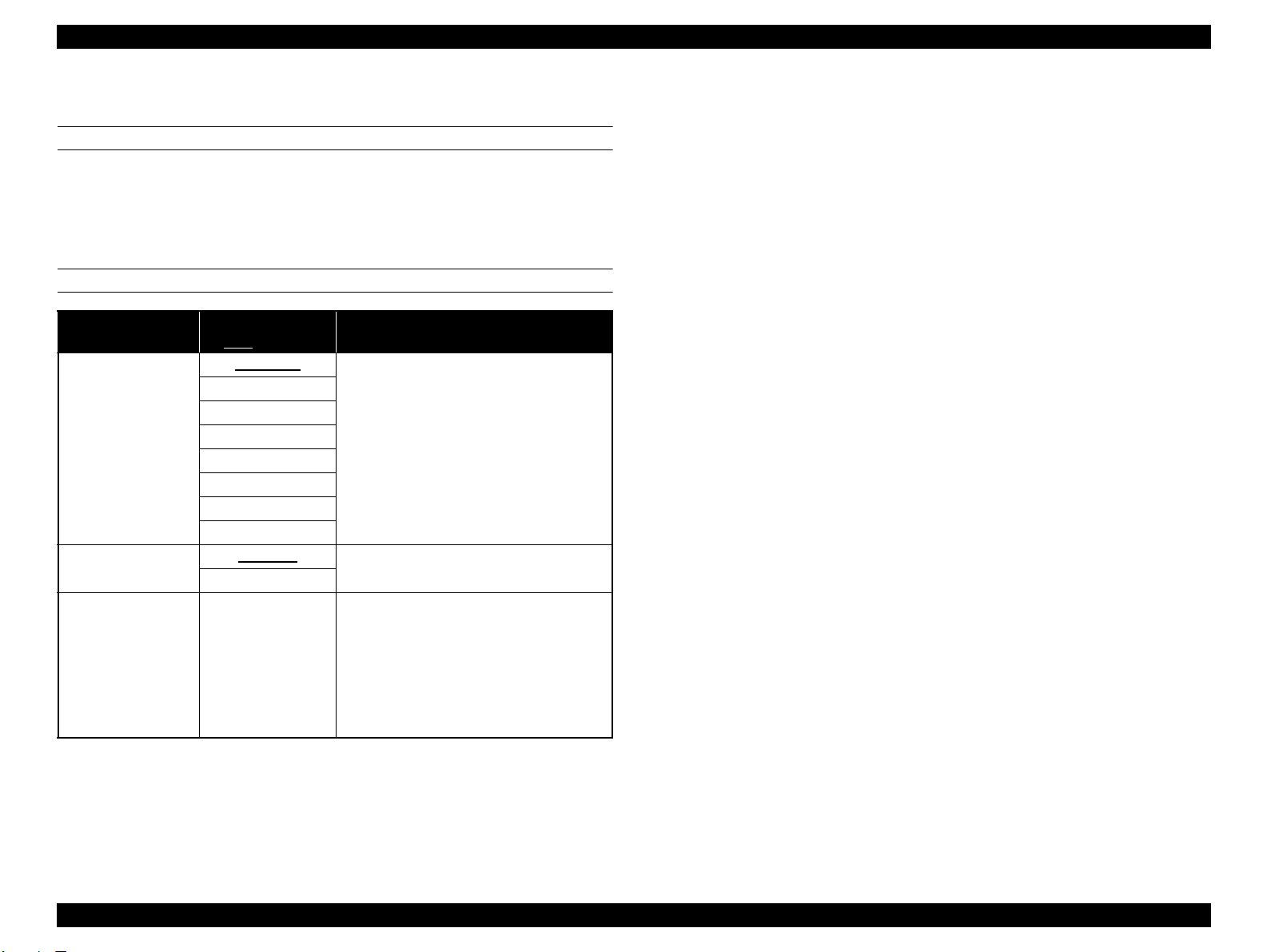
1.6.7 Maintenance Mode
HOW TO START & QUIT
Starting Method
Turn the printer On while holding down the Cancel/Reset button.
Quitting Method
Turn the printer Off.
MAINTENANCE MODE MENU LIST
Menu Item
LANGUAGE
UNIT
DEFAULT PANEL EXECUTE
Settings
= default)
(Bold
ENGLISH
JAPANESE
FRENCH
GERMAN
ITALIAN
PORTUGUE
SPANISH
DUTCH
METRIC
FEET/INCH
Explanation
Select the language to be displayed on the
LCD panel.
Select a unit of length to be used for various
length information.
All settings made in the following menus are
returned to their default.
PRINTER SETUP menu
PRINTER STATUS menu
CUSTOM PAPER menu
HEAD ALIGNMENT menu
NETWORK SETUP menu
PRODUCT DESCRIPTION Operation Panel 28
SE Group Confidential (Related Staff Only)
Page 29
Epson Stylus Pro 3800/3800C/3850/3880/3885/3890 Revision D
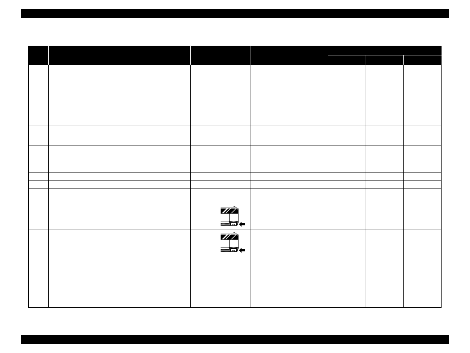
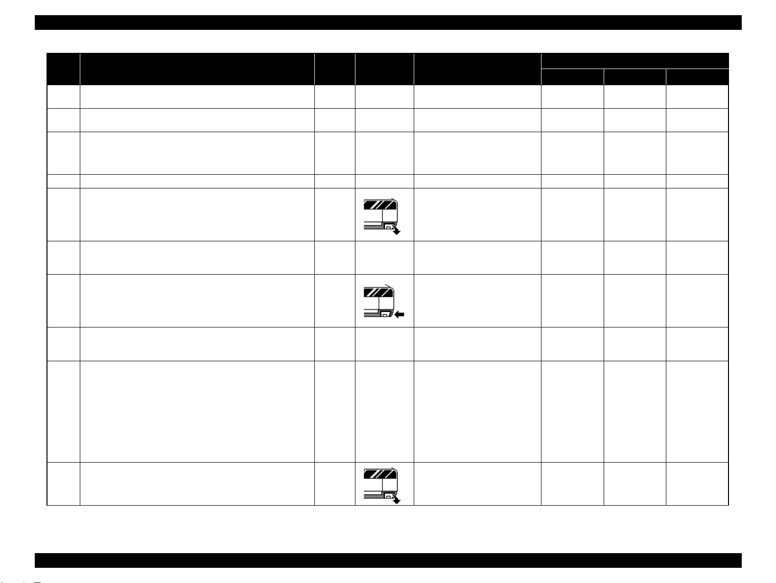
1.6.8 Error/Warning Statuses Displayed/Indicated on/by LCD/LED
No Error/Warning Status
1 FATAL ERROR (Service Call No. is displayed) Error --
FATAL ERR O R
2
(1st time: Restart Request is displayed/ 2nd time and later: Service Call
No. is displayed.)
FATAL ERR O R
3
(Always Resta r t Request is disp layed.)
FATAL ERR O R
4
(CR locked)
PAPER JAM
5
(Fatal Error)
6 Timer IC Reset/Clearing NVRAM (Pleas e wa it) -- -- PLEASE WAIT Light Light Light
7 Updating F/W (at normal startup) -- -- UPDATING FIRMWARE Blink Off Off
8 Canceling (including Job Cancel) -- --
9 No Maintenance Cartridge Error
10 Maint enance Cartridge Cover O pen Error
Paper Feed Failed
11
Reset
Board Paper Feed Failed
12
Reset
Error or
Warning
Error --
Error --
Error --
Error --
Error --
Error --
Illustration
on LCD
Message on LCD
SERVICE CALL ERROR
NNNN
PLEASE CONTACT TO THE
REPAIR CENTER
PRINTER ERROR
RESTART THE PRINTER
PRINTER ERROR
RESTART THE PRINTER
CARRIAGE LOCKED
RELEASE THE CARRIAGE
LOCK
PAPER JAM
CLEAR JAMMED PAPER
SEE PRINTER GUIDE
FOR INSTRUCTIONS
RESETTING
PLEASE WAIT
NO MAINTENANCE CART.
INSTALL THE
MAINTENANCE
CARTRIDGE.
MAINTENANCE COVER
OPEN
CLOSE THE
MAINTENANCE COVER
PAPER FEED ERROR
REMOVE PAPER
AND LOAD PAPER
CORRECTLY
PAPER FEED ERROR
LOAD PAPER CORRECTLY
AND PRESS PAPER/FEED
BUTTON
Power Paper Status Ink Status
Light Blink Blink
Light Blink Blink
Light Blink Blink
Light Blink Blink
Light Blink Blink
Light Light Light
Light Off Light
Light Off Light
Light Light Off
Light Light Off
LED
PRODUCT DESCRIPTION Operation Panel 29
SE Group Confidential (Related Staff Only)
Page 30
Epson Stylus Pro 3800/3800C/3850/3880/3885/3890 Revision D
No Error/Warning Status
Paper Jam Discharge Failed
13
Remove Paper
14 Waiting Cartridge Cover open -- --
15 Cartridge Cover Cannot Be Open ed Error --
16 Detecting Ink Cartridge (Cover close -> READY) -- -- PLEASE WAIT Light Off Off
17 Maintenance Cartridge Insufficient Error
18 Ink Cartridge Insufficient Error --
19 Maintenance Cartridge CSIC Read/Write Error Error
20 Not GENUINE maintenance cartridge error Error --
21 Not GENUINE maintenance cartridge error Error --
22 Maintenance Cartridge End Error
Error or
Warning
Error --
Illustration
on LCD
Message on LCD
PAPER JAM
REMOVE PAPER
RELEASING THE
INK COVER LOCK
CANNOT OPEN COVER
IS THERE ANYTHING ON
THE PRINTER?
PRESS THE UP BUTTON
NOT ENOUGH
EMPTY SPACE
REPLACE THE
MAINTENANCE
CARTRIDGE
NOT ENOUGH INK
REPLACE INK CARTRIDGE
WITH A NEW ONE
MAINTENANCE
CARTRIDGE
ERROR
REPLACE THE
CARTRIDGE
MAINTENANCE
PLEASE USE GENUINE
EPSON CARTRIDGES
MAINTENANCE
NON-GENUINE
MAINTENANCE
CARTRIDGE INSTALLED.
MAINTENANCE CAPACITY
TO ABSORB INK MAY
VARY.
CONTINUE?
<YES NO>
MAINTENANCE CART.
REPLACE MAINTENANCE
CARTRIDGE
Power Paper Status Ink Status
Light Light Off
Blink Off Off
Light Off Blink
Light Off Light
Light Off Light
Light Off Light
Light Off Light
Light Off Light
Light Off Light
LED
PRODUCT DESCRIPTION Operation Panel 30
SE Group Confidential (Related Staff Only)
Page 31

Epson Stylus Pro 3800/3800C/3850/3880/3885/3890 Revision D
No Error/Warning Status
23 Board paper removal error Error
Board Paper Tray Open Error
24
The tray was ope ned during operation
Board tray open error
25
Set paper
Board Tray Close Error
26
The tray was ope ned during operation
Board Tray Close Error
27
Paper needs to be removed
28 No Ink Cartridge Error --
29 Ink Cartridge CSIC Read/Write Error Error --
30 Not GENUINE ink cartridge error Error --
Error or
Warning
Error
Error
Error
Error
Illustration
on LCD
Message on LCD
FRONT FEED SLOT OPEN
PRESS THE
DOWN BUTTON
AND REMOVE
PAPER
FRONT FEED SLOT OPEN
CLOSE THE
FRONT MANUAL
FEED SLOT
FRONT FEED SLOT OPEN
LOAD MEDIA AND
PRESS THE
DOWN BUTTON
FRONT SLOT CLOSED
OPEN THE
FRONT MANUAL
FEED SLOT
FRONT SLOT CLOSED
OPEN THE
FRONT MANUAL
FEED SLOT
NO INK CARTRIDGE
INSTALL INK CARTRIDGE
INK CARTRIDGE ERROR
REPLACE CARTRIDGE
INK CARTRIDGE
PLEASE USE GENUINE
EPSON INK CARTRIDGE
INK CARTRIDGE
LED
Power Paper Status Ink Status
Light Light Off
Light Light Off
Light Light Off
Light Light Off
Light Light Off
Light Off Light
Light Off Light
Light Off Light
NON-GENUINE
CARTRIDGE!
QUALITY OF
31 Not GENUINE ink cartridge error Error --
NON-GENUINE
INK MAY VARY.
THIS MAY NOT
PERFORM AT OPTIMUM.
CONTINUE?
<ACCEPT DECLINE>
Light Off Light
PRODUCT DESCRIPTION Operation Panel 31
SE Group Confidential (Related Staff Only)
Page 32

Epson Stylus Pro 3800/3800C/3850/3880/3885/3890 Revision D
No Error/Warning Status
32 Ink End Error --
33 Ink Cover Open Error --
34 Ink Initial Refilling -- --
35 K Ink Changing -- --
36 Cleaning -- --
37 Command Error Error --
38 Paper Skew Error Error
39 Paper Identification Error (PW Inspection) Error
40 Borderless Prin ti ng Erro r Error --
Paper Discharge Failed Error (Cut Shee t Pa pe r)
41
Remove paper by paper disch arge key
42 Blank Sheet Discharge/Multifeed Error Error
43 Paper removal -- --
Error or
Warning
Error
Illustration
on LCD
Message on LCD
INK CARTRIDGE
REPLACE INK CARTRIDGE
INK COVER OPEN
CLOSE THE INK COVER
CHARGING INK
NN%
BLACK INK CHANGING
MATTE -> PHOTO NN%
CLEANING
PLEASE WAIT
COMMAND_ERROR
CHECK_DRIVER_SETTINGS
PAPER SKEW
PRESS THE
DOWN BUTTON.
LOAD PAPER
CORRECTLY
PAPER ERROR
PRESS THE
DOWN BUTTON.
LOAD PAPER
CORRECTLY
BORDERLESS ERROR
PRESS_THE DOWN BUTTON
LOAD THE CORRECT SIZE
PAPER
PAPER EJECT_ERROR
PRESS THE
DOWN_BUTTON
AND REMOVE
PAPER
PAPER FEED ERROR
LOAD PAPER
CORRECTLY
PRESS THE
DOWN BUTTON
PAPER REMOVE
REMOVE PAPER
FROM THE REA R
LED
Power Paper Status Ink Status
Light Off Light
Light Off Light
Blink Off Off
Blink Off Off
Blink Off Off
Blink Blink Blink
Blink Off Light
Light Blink Off
Light Blink Off
Light Blink Off
Light Light Off
Light Light Off
PRODUCT DESCRIPTION Operation Panel 32
SE Group Confidential (Related Staff Only)
Page 33

Epson Stylus Pro 3800/3800C/3850/3880/3885/3890 Revision D
No Error/Warning Status
44 No Paper Error --
45 Paper Size Check Error Error --
46 Ink Mark Sensor Sensitivity Control Error Error --
Ink Mark Sensor Adjusted Value Erro r
Adjusted value cannot be set
47
Adjusted range over
Nozzle Check Error
48
Nozzle cannot be recovered
Cleaning Error
W/ board paper
49
Before printing when PW inspection is OFF
50 During Initialization -- -- PLEASE WAIT Blink Off Off
51 During Sequence -- -- PLEASE WAIT Blink Off Off
52 Paper Initial Trigger Waiting Status (No waiting time) -- -- READY Light Off Off
53 Paper Initial Trigger Waiting S tatus (Auto loading) -- -- READY Light Off Off
54 Paper Setting Error Error --
55 Interna l P attern Printing -- -- PRINTING Blink Off Off
56 Setting Panel Error -- SETTING... Light Off Off
57 Initializing Paper -- -- PLEASE WAIT Light Off Off
58 Ink Drying -- --
59 Maintenance Call Warning Warning --
60 Ink Low Warning Warning -- INK LOW Light Off Blink
Error or
Warning
Error --
Error --
Error
Illustration
on LCD
Message on LCD
PAPER ERROR
LOAD PAPER
PAPER SIZE ERROR
LOAD THE CORRECT SIZE
PAPER
PAPER SENSOR ERROR
PRESS THE BUTTON
LOAD DIFFERENT PAPER
PAPER_SENSOR_ERROR
PRESS THE BUTTON
LOAD THE CORRECT PAPER
CLEANING ERROR
PRESS THE CANCEL/RESET
BUTTON
CLEANING_ERROR
PRESS THE
DOWN BUTTON
AND REMOVE
THICK PAPER
PAPER SETTING ERROR
CHECK PAPER SOURCE_IN
THE DRIVER SETTINGS
AND LOAD PAPER
CORRECTLY
INK_DRYING
NNNN_SEC
MAINTENANCE_REQUEST
NNNN
Power Paper Status Ink Status
Light Light Off
Light Blink Off
Light Blink Off
Light Blink Off
Light Blink Blink
Light Light Off
Light Light Off
Blink Off Off
Light Special Blink Off
LED
PRODUCT DESCRIPTION Operation Panel 33
SE Group Confidential (Related Staff Only)
Page 34

Epson Stylus Pro 3800/3800C/3850/3880/3885/3890 Revision D
No Error/Warning Status
61 Maint enance Cartridge Cover Open Warning Warning
62 Maintenance Cartridge Low Warning --
63 Printing -- -- PRINTING Blink Off Off
64 Analyzing -- -- READY Blink Off Off
65 Printable (Idlin g) -- --
Error or
Warning
Illustration
on LCD
Message on LCD
MAINTENANCE COVER
OPEN
CLOSE THE
MAINTENANCE
COVER
REPLACE MAINTENANCE
CARTRIDGE SOON
READY
PHOTO_BLACK
Power Paper Status Ink Status
Light Off Blink
Light Off Blink
Light Light Light
LED
PRODUCT DESCRIPTION Operation Panel 34
SE Group Confidential (Related Staff Only)
Page 35

OPERATING PRINCIPLES
CHAPTER
2
SE Group Confidential (Related Staff Only)
Page 36

Epson Stylus Pro 3800/3800C/3850/3880/3885/3890 Revision D
2.2 Print Mechanism
Describes basic specifications of the print
mechanism (print head).
<Main Component>
• Print Head
2.3 Ink Supply Mechanism
Explains how the ink is supplied from the
cartridges to the print mechanism.
<Main Components>
• Ink Cartridge
• Ink Cartridge Holder
•Damper
•Pressure Pump
• Ink change system
2.4 Cleaning Mechanism
Explains how the print head is cleaned.
<Main Component>
• Pump Cap Unit
2.5 Carriage Mechanism
Explains how to move the Carriage Unit.
<Main Components>
• CR Motor
• CR Scale
• Timing Belt
• CR Encoder
2.6 Paper Feed Mechanism
Explains how paper is fed and
transported.
<Main Components>
•PF Motor
•ASF
• PE Sensor
• Paper Eject Tray
2.1 Overview
OPERATING PRINCIPLES OVERVIEW
OPERATING PRINCIPLES Overview 36
SE Group Confidential (Related Staff Only)
Page 37

Epson Stylus Pro 3800/3800C/3850/3880/3885/3890 Revision D
123
4
1
2
3
4
MAIN COMPONE NT
Electric Circuit Boards
Table 2-1. List of Electric Circuit Boards
Fig. Name Function
Communications with host computer
Main board
Epson Stylus Pro 3800/3800C/
3850: C635 MAIN
Epson Stylus Pro 3880/3885/
3890: CA61 MAIN
Power supply boar d
(C635 PSB/PSE)
Panel board (C635 PN L)
Sub board (C635 SUB)
Receive data processing
Engine control
Saves compensation values and various counter
information.
Generates power voltages used by the logic circuits
from 42 V supplied from the power supply board.
Generates power system power voltage 42 V from
the AC power supply
Printer operations, various settings
Shows printer status and various setting values on
the LCD.
Indicates printer status by the LED.
Relays connections between the main board and the
following parts:
PG sensor
Ink mark sensor
PW sensor
Ink change sensor
CR encoder
Ink change motor
Figure 2-1. Layout of Electric Circuit Boards
OPERATING PRINCIPLES Overview 37
SE Group Confidential (Related Staff Only)
Page 38

Epson Stylus Pro 3800/3800C/3850/3880/3885/3890 Revision D
1
2
3456789
1
2
3
4
5
7
8
9
6
Motors/Solenoid
Table 2-2. List of Motors/Solenoid
Fig. Name
Release motor
PF motor
Ink cover unlock solenoid
Pressure pump motor
Ink change motor
Pump motor
CR motor
APG motor
ASF motor
Driven Parts
Specifications
Release r ol ler
Type: DC motor
±
±
±
±
±
±
±
±
±
5 %
5 %
5 %
5 %
5 %
5 %
5 %
5 %
5 %
Figure 2-2. Layout of Motors/Solenoid
Voltage:42 VDC
PF roller
Paper eject roller A
Paper eject roller B
Type: DC motor
Voltage:42 VDC
Ink cover unlock mechanism
Type: DC solenoid
Voltage:42 VDC
Pressure pump
Type: DC motor
Voltage:42 VDC
Ink change system
Type: DC motor
Voltage:42 VDC
Pump cap unit
Type: 4-phase 48-pole PM stepping motor
Voltage:42 VDC
Carriage unit
Type: DC motor
Voltage:42 VDC
Platen gap mechanism
Type: 4-phase 96-pole PM stepping motor
Voltage:42 VDC
ASF unit
Type: 4-phase 96-pole PM stepping motor
Voltage:42 VDC
OPERATING PRINCIPLES Overview 38
SE Group Confidential (Related Staff Only)
Page 39

Epson Stylus Pro 3800/3800C/3850/3880/3885/3890 Revision D
1
2
345
67891011121314
15
16
16
15
14
9
3
10
12
8
2
11
1
4
5
6
7
13
Sensors/Encoders/CSIC
Table 2-3. List of Sensors/Encoders/CSIC
Fig. Name Function Specifications
ASF phase sensor
Release sensor
PF encoder Reads the PF scale.
Ink cover sensor
Pressure pump home
sensor
Pressure sensor
Board paper t ray open
sensor
Ink cartridge sensor
PG origin sensor
v
Ink change sensor
Ink mark sensor
Maintenance cartridge
cover sensor
PW sensor
Maintenance cartridge
sensor
Detects the ASF origin
position.
Detects an open/closed
state of the release roller.
Detects an open/closed
state of the ink cover.
Detects the home
position of the pressure
pump.
Detects the state of
pressurization by the
pressure pump.
Detects the position of
the board paper tray.
CSIC that stores ink
cartridge information
Detects the origin
position of the platen
gap.
Detects the state of the
black ink switch lever.
Auto Bi-D adjustment
Auto
Uni-D
Auto nozzle check
Detects an open/closed
state of the maintenance
cartridge cover.
Paper leading edge
detection
Paper width detection
CSIC that stores
maintenance cartridge
information.
adjustment
Type: Transmissive photo interrupter
Voltage: 3.3 VDC
Type: Transmissive photo interrupter
Voltage: 3.3 VDC
Type: Linear encoder (180LPI)
Voltage: 3.3 VDC
Type: Mechanical contact
Voltage: 3.3 VDC
Type: Mechanical Contact
Voltage: 3.3 VDC
Type: Reflective photo inte rrupter
Voltage: 3.3 VDC
Comparator input
Type:Mechanical Contact
Voltage: 3.3 VDC ± 5 %
Type: CSIC
Voltage: 3.3 VDC
Type: Transmissive photo interrupter
Voltage: 3.3 VDC
Type: Mechanical contact
Voltage: 3.3 VDC
Type:
Voltage:3.3 VDC ± 5 %, LED: 5 V
Type: Mechanical contact
Voltage: 3.3 VDC
Type: Reflective photo inte rrupter
Voltage: 3.3 VDC ± 5 %, LED: 3.3 V
Type: CSIC
Voltage: 3.3 VDC
Diffuse reflective photo interrupter
±
±
±
±
±
±
±
±
±
±
±
5 %
5 %
5 %
5 %
5 %
5 %,
5 %
5 %
5 %
5 %
5 %
Table 2-3. List of Sensors/Encoders/CSIC
Fig. Name Function Specifications
PE sensor
CR encoder Reads the CR scale.
Detects a rear edge of
paper.
Type: Transmiss ive ph ot o interr up ter
±
±
5 %
5 %
Voltage: 3.3 VDC
Type: Linear Encoder (180LPI)
Voltage: 3.3 VDC
Figure 2-3. Layout of Sensors/Encoders/CSIC
OPERATING PRINCIPLES Overview 39
SE Group Confidential (Related Staff Only)
Page 40

Epson Stylus Pro 3800/3800C/3850/3880/3885/3890 Revision D
Paper Feed Direction
Carriage Moving D irection
2.2 Print Mechanism
This section explains the basic specifications of the print head.
NOZZLE CONFIGURATION AND COLORS
This printer is equipped with an MACH print head, which employs 180 nozzles per
color. The printer ejects nine different colors of ink through the eight rows of nozzles.
One of the rows is shared by Photo Black and Matte Black inks.
The nozzle configuration as seen from behind the print head is shown below.
Printing method: On-demand ink-jet
Nozzle configuration: 180 nozzles x 8 rows = 1440 nozzles
Table 2-4. Nozzle Rows and Colors
Nozzle Row
A
B
C
D
E
F
G
H
Epson Stylus Pro 3800/3800C/3850 Epson Stylus Pro 3880/3885/3890
Magenta Vivid Magenta
Photo Black/Matt Black
Light Magenta Vivid Light Magenta
Color
Cyan
Yellow
Light Light Black
Light Black
Light Cyan
DRIVE WAVEFORMS
The following four drive waveforms are used to create four print modes.
Table 2-5. Print Modes (Drive Waveforms)
Waveform
Name
VSD1 10.08 360 x 360 280
VSD1 10.08
VSD2 10.08 1440 x 720 280
VSD3 20.16 2880 x 1440 280
Drive Frequency
(kHz)
Print Resolution
(dpi)
720 x 360
720 x 720
CR Speed
(cps)
280
Figure 2-4. Nozzle Configuration
OPERATING PRINCIPLES Print Mechanism 40
SE Group Confidential (Related Staff Only)
Page 41

Epson Stylus Pro 3800/3800C/3850/3880/3885/3890 Revision D
Ink Cartridge
Print Head
Ink Selector
+
Dumper
To Print Head
Pressure Pump
Ink Cartridge
Air flow path
Ink flow path
Pressure Sensor Uni t
2.3 Ink Supply Mechanism
2.3.1 Ink Flow Path
The ink flow path is shown below.
2.3.2 Ink Pressurizing Mechanism
This printer employs an ink pressurizing mechanism to stably supply ink in the ink
cartridge (ink pack) to the print head. This ink pressurizing mechanism consists of a
pressure pump unit installed in an ink supply mechanism and tightly-sealed ink
cartridges. Air pumped into the tightly-sealed ink cartridge from the pressure pump
unit squashes the ink pack in the cartridge, causing the ink inside the pack to be
transferred to the print head.
OPERATING PRINCIPLES Ink Supply Mechanism 41
Figure 2-5. Ink Flow Path
Figure 2-6. Ink Pressurizing Mechanism
SE Group Confidential (Related Staff Only)
Page 42

Epson Stylus Pro 3800/3800C/3850/3880/3885/3890 Revision D
Combinati on Gear, 18, 39
Clutch
Spur Gear, 24.5
Spur Gear, 22
Regulator
Pressure pump motor
Accordion Unit
Reducing
pressure
Applying
pressure
CW rotation CCW rotation
Clutch
Spur Gear, 22
Spur Gear, 24.5
Accordion U nit
Pressure
Pump Motor
Valve
Clutch
Applying pressure
CW rotation of the
clutch close s the valve
and applies pressure to
send air toward the ink
cartridges.
Reducing pressure
CCW rotation of the clutch opens
the valve and redu ces pressure.
When the air pressure reaches
the predetermined level, the
valve opens as the pressure
overcomes the tension of the
spring that presses the valve.
Combination Gear 18, 3.9
Regulator
Pressure Sensor Unit
Sensor
Pressure Pump
Home Sensor
Air Damper Film
2.3.2.1 Pressure Pump Unit Mechanism
Accordion unit/Pressure pump motor/Pressure pump home sensor
The accordion unit intakes air and applies pressure by the rotating drive of the pressure
pump motor, and pumps air into the ink cartridges. The pressure pump home sensor
detects the position of the accordion unit.
Pressure sensor unit
A reflective photo sensor, which turns on when the air pressure reaches the
predetermined level, controls the amount of pressure. When the air pressure reaches
the predetermined level, film on the air damper expands and activates the reflective
plate causing the sensor to receive light, and the pressurizing state is detected.
Regulator
Stops applying pressure when the power is off or during stand-by. Activated by the
pressure pump motor through the clutch. The regulator opens the valve to reduce
pressure.
Figure 2-7. Drive Transmission Path
OPERATING PRINCIPLES Ink Supply Mechanism 42
Figure 2-8. Pressure Pump Unit
SE Group Confidential (Related Staff Only)
Page 43

Epson Stylus Pro 3800/3800C/3850/3880/3885/3890 Revision D
Ink Change Motor
Ink Change Sensor
Selection Cam
Selection Lever
Changing to Photo Black
Selection pin
Matt Black
Photo Black
Photo Black
Ink Path
Selection
Cam
Pressure of
Selection
Lever
Changing to Matte Black
Selection
Lever
Matte Black
2.3.3 Ink Change System
This printer has automatic ink change system that switches black ink between Photo
Black and Matte Black. The cartridge holder of this printer keeps both Photo Black and
Matte Black ink cartridges. Each of the black ink cartridges has its own ink supply tube
connected to their respective damper. Both black inks are supplied into the damper, and
one of them is supplied to the print head at one time by means of the ink selector that
changes the ink flow path.
Ink change system consists of an ink change moto r, selection cam, selection lever, and
ink change sensor. The following describes the mechanism.
1. Drive of the ink change motor rotates the selection cam.
Ink change sensor detects the rotation angle of the cam.
2. The selection lever moves as the selection cam rotates.
3. The protruded end of the selection lever pushes the selection pin, and the pin
changes the black ink flow path inside the damper.
Figure 2-9. Ink Change System
Figure 2-10. Changing Black Ink Path
OPERATING PRINCIPLES Ink Supply Mechanism 43
SE Group Confidential (Related Staff Only)
Page 44

Epson Stylus Pro 3800/3800C/3850/3880/3885/3890 Revision D
Cap Unit
Pump Motor
Combination Gear, 16, 11.5
Combination Gear, 13.5, 10
Pump
Head Cleaner
Combination Gear, 15.5, 9.5
Spur Gear, 26.5
Spur Gear, 13
Spur Gear, 21.5
Intermittent Gear, 21.5
Carriage Lock
Cap Unit
Intermittent
Gear, 21.5
Combination Gear, 15.5, 9. 5
Spur Gear, 26.5
Pinion Gear
(Pump Motor)
Carriage Lock
Spur Gear, 21.5
Cap unit moves up
(capped, locked)
Cap unit moves down
(uncapped, unlocked)
Spur Gear, 13
2.4 Cleaning Mechanism
The cleaning mechanism consists of a pump cap unit and a waste ink pads
(maintenance cartridge).
Pump Motor
The pump motor drives the cap unit, pump, head cleaner, and carriage lock. The table
below shows the operation of each mechanism depending on the rotation al direction of
the pump motor.
Table 2-6. Pump Motor Functions
Mechanism CCW * CW *
Cap Unit Open (Uncapping) C lose (Capping)
Pump Pump release Pump suction
Head Cleaner
Wiper reset
(back to the home)
(moves to the wiping position)
Carriage Lock Unlock Lock
Note *: The rotation direction as seen from the top of the unit.
Wiper set
Cap Unit/Carriage Lock
The pump motor moves the cap unit up and down. The cap unit goes up to seal the
print head during cleaning and stand-by. Carriage lock operates in synchronization
with the cap unit. When the carriage unit moves to the home position, carriage lock
moves up together with the cap unit and lock the carriage unit.
OPERATING PRINCIPLES Cleaning Mechanism 44
Figure 2-11. Drive Transmission Path
Figure 2-12. Cap Unit/Carriage Lock Mechanism
SE Group Confidential (Related Staff Only)
Page 45

Epson Stylus Pro 3800/3800C/3850/3880/3885/3890 Revision D
To Waste Ink Pad
Head Nozzle
Conveyance Roller
Combination
Gear,15.5, 9.5
Intermittent Gear, 21.5
Spur Gear, 26.5
Spur Gear,13
Head Cleaner
Combination
Gear, 16, 11.5
Pinion Gear
(Pump Motor)
Combination
Gear, 13 .5, 10
Combination
Gear, 13 .5, 10
Spur Gear, 21.5
Pump Unit
The ink is absorbed from the head nozzles. The sucked waste ink is conveyed to the
waste ink pad through the tube.
The CW rotation of the pump motor rotates the conveyance roller. The roller rotates
pressing the tube to convey the waste ink from the cap unit to the waste ink pad.
The CCW rotation of the pump motor moves the conveyance roller away from the
pressing position.
Head Cleaner
The head cleaner wipes off ink, dirt or the like from the surface of the head nozzles.
The CW rotation of the pump motor moves the head cleaner to the wiping position.
OPERATING PRINCIPLES Cleaning Mechanism 45
Figure 2-13. Pump Unit Mechanism
Figure 2-14. Head Cleaner Mechanism
SE Group Confidential (Related Staff Only)
Page 46

Epson Stylus Pro 3800/3800C/3850/3880/3885/3890 Revision D
CR Encoder
Carriage Guide Shaft
CR Timing Belt
CR Scale
CR Scale
CR Motor
Carriage Unit
2.5 Carriage Mechanism
The carriage mechanism consists of a carriage movement mechanism, platen gap
adjustment mechanism, and carriage lock mechanism. For explanation about the
carriage lock mechanism, refer to Cap Unit/Carriage Lock (p.44).
2.5.1 Carriage Movement Mechanism
Carriage movement mechanism consists of a carriage unit, CR motor, timing belt,
carriage guide shaft, CR scale, and CR encoder.
Rotational drive of the CR motor is transmitted to the carriage unit through the timing
belt, and the carriage unit moves left and right along the carriage guide shaft. The CR
encoder installed on the back of the carriage unit reads the jagged surface of the CR
scale and sends the read value to the main board. Position and moving speed of the
carriage unit are controlled based on the read value.
Figure 2-15. Carriage Movement Mechanism
OPERATING PRINCIPLES Carriage Mechanism 46
SE Group Confidential (Related Staff Only)
Page 47

Epson Stylus Pro 3800/3800C/3850/3880/3885/3890 Revision D
PG Shaft
Cam
Sub Carriage
Spur Gear, 29.6
Spur Gear, 34.4
APG Motor
Combination Gear, 13.6, 31.2
Combinati on Gear, 20, 34.4
PG Sensor
Lightshielding
Plate
Cam
Cutout
Spur Gear, 34.4
Spur Gear, 29.6
Combination
Gear,20, 34.4
Sub Carriage
Main Carriage
Cam
APG Motor
Combination
Gear,13.6, 31.2
Narrow Wide
2.5.2 Platen Gap Adjustment Mechanism
Platen gap adjustment mechanism consists of an APG motor, carriage unit, and PG sensor.
The carriage unit is equipped with two carriages; main carriage that moves horizontally to
the carriage guide shaft, and the sub carriage that moves vertically to the main carriage.
When the carriage unit moves to the PG adjustment position and the APG motor starts to
rotate, the oval cam turns to move the sub carriage vertically and change the platen gap
amount. Light-shielding plate with a cutout is installed at the end of the shaft to which the
cam is attached, and moves together with the cam. A transmissive photo interrupter sensor
(PG sensor) detects the cutout, determines the detected position as the origin, and changes
the platen gap according to the number of pulses from the origin.
Figure 2-16. Drive Transmission Path
The relation between the printer status and the platen gap amount is described below.
Table 2-7. PG Positions in Operations
Table 2-7. PG Positions in Operations
Operation PG
Detecting paper width
(ASF feeding, Rear /Front manual feeding)
Detecting paper width
(ASF feeding after receiving data)
Switch PG according to the print setting.
Starts printing Switch PG according to the print setting.
At power OFF 1.2
3.5
Operation PG
At power ON 1.2
Cleaning starts 1.5
Capping Capping is done in the current PG.
Board paper tray is op e n 3.5
OPERATING PRINCIPLES Carriage Mechanism 47
Figure 2-17. Platen Gap Adjustment Mechanism
SE Group Confidential (Related Staff Only)
Page 48

Epson Stylus Pro 3800/3800C/3850/3880/3885/3890 Revision D
123
1
2
3
2.6 Paper Feed Mechanism
2.6.1 Paper Feed Path
The printer provides two manual paper feed paths in addition to the ASF to support
thicker paper.
Paper Feeding Thickness Type
ASF (Auto Sheet Feeder) 0.08 to 0.27 mm See 1.3.3 Paper Support (p.15)
Rear Manual Bypass 0.29 to 0.5 mm Fine Art Paper
Front Manual Bypass 1.2 to 1.5 mm Heavy paper like cardboard
The following figures show the paper feed paths.
Figure 2-19. Paper Path of Front Manual Bypass
Figure 2-18. Paper Path of ASF & Rear Manual Bypass
OPERATING PRINCIPLES Paper Feed Mechanism 48
SE Group Confidential (Related Staff Only)
Page 49

Epson Stylus Pro 3800/3800C/3850/3880/3885/3890 Revision D
LD Roller Shaft
ASF Motor
Hopper
Paper Anti-slipTab
Lever
Hopper Actuating Cam
Hopper
Standby Raising
LD Roller
LD Roller
Retard Roller
Hopper
Paper
Separation Pad
2.6.2 Paper Loading Mechanism
ASF (AUTO SHEET FEEDER)
The ASF, whose driving source is an ASF motor, consists of a LD roller, LD roller
shaft, ASF sensor, hopper, and paper anti-slip tab. The cams on both ends of the LD
roller shaft activate the hopper and the paper anti-slip tab. The ASF sensor (photo
interrupter sensor) controls the rotational position of the LD roller shaft by detecting
the light-shielding plate installed on the shaft. Paper loading operation fr om the ASF i s
described below:
1. Start of the paper loading operation
The ASF motor moves to rotate the LD roller shaft.
2. Feeding paper to the paper lo ading position
2-1. The LD roller shaft rotates to release the lever that presses the paper anti-
slip tab, a nd the tabs go down.
2-2. The LD roller shaft rotates to release the hopper actuating the cam that
presses the hopper, and the hopper moves up by the tension of the spring.
Figure 2-21. Raising the Hopper
3. Picking-up paper
The LD roller shaft rotates to feed a single sheet of paper into the printer with a LD
roller.
Figure 2-20. Lowering the Paper Anti-slip Tab
OPERATING PRINCIPLES Paper Feed Mechanism 49
Figure 2-22. Picking-up Paper
SE Group Confidential (Related Staff Only)
Page 50

Epson Stylus Pro 3800/3800C/3850/3880/3885/3890 Revision D
Hopper
Hopper
Actuating
Cam
groove
LD Roller Shaft
Paper Holding State Paper Releasing State
Spur Gear,
Shaft, LD
Paper Anti-sli p Tab
LD Roller Shaft
LD Roller
ASF Motor
Combination
Gear, 58.22
Hopper
ASF Sensor
Retard Roller
Position Detection Section
ASF Motor
Spur Gear, Shaft, LD
Paper Anti-slip Tab
LD Roller Shaft
Hopper Assy
Combination Gear, 58,22
LD Roller
4. Pressing the hopper
The hopper cam on the LD roller shaft presses the hopper and remaining paper on
the tray is moved away from the feeding position.
5. Moving the paper anti-slip tabs upward
The LD roller shaft rotates to actuate the lever on the shaft and move the paper
anti-slip tabs upward. The tabs prevent the paper from slipping into the paper
feeding section.
6. Transporting paper in the printer
Paper fed into the printer is transported by the PF roller.
7. Releasing the back end of paper
When the hopper actuating cam pr esses the hopp er further in synchr onization with
the rotation of the LD roller, left and right paper guides that regulate the paper
width are extended releasing the back end of paper.
8. Standing-by
The hopper returns to the stand-by position and ends the paper loading operation.
OPERATING PRINCIPLES Paper Feed Mechanism 50
Figure 2-23. Releasing the Back End of Paper
Figure 2-24. ASF Drive Mechanism
Figure 2-25. ASF Drive Transmission Path
SE Group Confidential (Related Staff Only)
Page 51

Epson Stylus Pro 3800/3800C/3850/3880/3885/3890 Revision D
Board Paper Tray
Tray Closed
Tray Open
Board Paper
Guide Cam
Leaf Switch
REAR MANUAL BYPASS
When the prescribed time has passed since a paper was supplied from the feeder o n the
rear of the printer and the PE sensor detected the paper, the PF roller starts to transport
the paper.
FRONT MANUAL BYPASS
The status of the board paper tray that is used for the front manual feeding is detected
by the leaf switch. The leaf switch is moved by the Board Paper Guide Cam which
moves together with the board paper tray, and according to the switch position, the
board paper tray status is detected.
Figure 2-26. Board Paper Tray Open Sensor
OPERATING PRINCIPLES Paper Feed Mechanism 51
SE Group Confidential (Related Staff Only)
Page 52

Epson Stylus Pro 3800/3800C/3850/3880/3885/3890 Revision D
Release Motor
Combinati on Gear, 9.6, 22
Spur Gear, 22
Combination Gear, 8, 22
Paper Guide Upper Assy
Spur Gear, 22.B
Combination Gear, 8, 22
Combination Gear, 8, 22.986
Spur Gear, 20.4
Combinati on Gear, 22, 32 . 4
Light-shielding Plate
Paper Guide Release Shaft
2.6.3 Paper Feed Mechanism
The paper feed mechanism mainly consists of a Release mechanism, the PF Motor, and
the feed rollers.
RELEASE MECHANIS M
Release mechanism consists of a release unit (includ ing a release mo tor, release sensor,
and combination gear), paper guide upper assy that presses papers, and paper guide
release shaft that activates the paper guide upper assy.
Rotational drive of the release motor activates the paper guide release shaft through th e
combination gear. When the release lever of the paper guide release shaft presses down
the back end of the paper guide upper assy, the paper guide upper assy separates from
the PF roller. When the release motor rotates reversely, the paper guide upper assy
makes contact with the PF roller. The release sensor installed in the release unit and the
light-shielding plate detects the contact condition between the paper guide upper assy
and the PF roller.
Figure 2-27. Drive Transmission Path
OPERATING PRINCIPLES Paper Feed Mechanism 52
SE Group Confidential (Related Staff Only)
Page 53

Epson Stylus Pro 3800/3800C/3850/3880/3885/3890 Revision D
Paper Guide R elease Shaft
Paper Guide
Upper Assy
Paper Guide Upper Assy
Light-shielding
Plate
Release Sensor
Release Motor
Spur Gear, 20.4
Combination
Gear, 8, 22.986
Combination
Gear, 9.6, 22
Spur Gear, 22
Combination
Gear, 8, 22
Spur Gear, 22,B
Combination
Gear, 22, 32.4
PF Roller
Holding status Re leasi ng status
Figure 2-28. Release Mechanism
OPERATING PRINCIPLES Paper Feed Mechanism 53
SE Group Confidential (Related Staff Only)
Page 54

Epson Stylus Pro 3800/3800C/3850/3880/3885/3890 Revision D
PF Motor
PF Motor
PF Timing Belt
Combinat ion Gear, PF, D rive
Spur Gear, 14.4
Spur Gear, 68
Front Paper Eject Ro ller
Spur Gear, 31.5
Rear Paper Ejec t R oller
PAPER FEED MECHANISM
Paper feed mechanism consists of a PF motor, PF scale, PF encoder, PF roller, front
and rear paper eject rollers, and star wheels. The mechanism transpo rts papers fed from
the feeders and ejects them from the front of the printer.
Figure 2-29. Drive Transmission Path
OPERATING PRINCIPLES Paper Feed Mechanism 54
SE Group Confidential (Related Staff Only)
Page 55

Epson Stylus Pro 3800/3800C/3850/3880/3885/3890 Revision D
Frame, EJ Assy
Star Wheel
Rear Paper Eject Roller
PF Encoder
Spur Gear, 68
Spur Gear, 31.5
PF Scale
Combination Gear, PF, Drive
PF Timing Belt
PF Motor
PF Roller
Paper
Front Paper Eject R oller
Spur Gear, 14.4
Figure 2-30. Paper Feed Mechanism
OPERATING PRINCIPLES Paper Feed Mechanism 55
SE Group Confidential (Related Staff Only)
Page 56

Epson Stylus Pro 3800/3800C/3850/3880/3885/3890 Revision D
2.7 Ink Mark Sensor
This printer is equipped with the ink mark sensor functioning as multi sensors.
The sensor, located on the bottom of the carriage unit, is a diffuse reflective
photointerruptor that is comprised of a light emitting part (white LED) and a light
receiving part (photoreceiver). The white LED emits light against the paper or
dedicated print pattern printed on paper and the pho toreceiv er reads the ref l ected light.
According to the reflected light read by the receiver, the printer calculates correction
values to perform proper corrective actions.
The Ink mark sensor is used for the following adjustments.
Auto Bi-D Adjustment
The sensor scans predetermined patterns printed for the adjustment and detects the
highest density pattern among them. According to the detected result, the printer
calculates Bi-D correction values automatically.
Auto Uni-D Adjustment
The sensor scans predetermined patterns printed for the adjustment and detects the
highest density pattern among them. According to the detected result, the printer
calculates Uni-D correction values automatically.
Auto Nozzle Check
The sensor scans a nozzle check pattern. The pattern is printed with the all nozzles and
each nozzle prints one block. If there is a clogged nozzle, the corresponding block will
not be printed and detected by the sensor, and a head cleaning is performed
automatically.
OPERATING PRINCIPLES Ink Mark Sensor 56
SE Group Confidential (Related Staff Only)
Page 57

Epson Stylus Pro 3800/3800C/3850/3880/3885/3890 Revision D
Ink Cover
Ink Cover SensorSolenoid Unit
Solenoid
Ink Cover Closed
Ink Cover Open
Maintenance Cartridge Cover Sensor
Maintenance Cartridge Cover
Cover Closed Cover Open
2.8 Other Mechanisms
INK COVER OPEN-CLOSE MECHANISM
To keep the ink cartridges from being removed durin g pri nti ng , open ing/ cl osi ng of the
ink cover is electrically regulated. Opening/closing of the cover is controlled by the
lock mechanism that takes advantage of an electromagnetic solen oid, and the cover can
only be opened by means of the o peratio n pa n el. W hen the op eration to op en the cov e r
is performed, the solenoid is energized and the lock is released. The solenoid unit is
equipped with a switch sensor that detects opening/closing state of the cover.
MAINTENANCE CARTRIDGE COVER OPEN DETECTION
To keep the maintenance cartridge from being removed during printing, a switch
sensor detects opening/closing state of the cover that stores the maintenance cartridge.
Figure 2-32. Operation of Maintenance Cartridge Cover
Figure 2-31. Ink Holder Cover Open/Close Mechanism
OPERATING PRINCIPLES Other Mechanisms 57
SE Group Confidential (Related Staff Only)
Page 58

Epson Stylus Pro 3800/3800C/3850/3880/3885/3890 Revision D
Custom
ASIC
E01A68C
(IC15)
Custom
ASIC
E09A54RA
(IC11㧕
Ethenet 10/100BASE-TX
BCM5980A2KFBG(IC10)
A6628 (IC13)
A6627 (IC6)
DDR-SDRAM
(IC3)
RTC9824
(IC9)
Flash ROM
(IC4)
Flash ROM
(IC1)
CN40
CR Motor
CN43
ASF Motor
CN44
Ink Change Motor
A6628 (IC7)
CN45
Pressurizing Pump Motor
CN57
Release Motor
CN58
CN41
PF Motor
CN41
APG Motor
CN67
USB I/F 2.0
CN102
Network
CN69/70/
71/72
Print Head
Pump Motor
(IC19)
DDR-SDRAM
(IC5)
SDRAM
(IC8)
SDRAM
2.9 Outline of Circuit Boards
Circuit block diagram
2.9.1 Main Board
This section provides a summary of the main board (Epson Stylus Pro 3800/3800C/
3850: C653 MAIN / Epson Stylu s Pro 3880/ 3885/3890 : CA61 MAIN ) that contro ls the
whole of the printer system.
Explanation of main elements on C635/CA61 MAIN Board
Table 2-8. Main Elements
Model Numbe r Location Function
E01A68CB IC15 Customized ASIC
FlashROM IC4
DDR-SDRAM IC3/IC19
RTC9824 IC9
E09A54RA IC11 Printer driver
A6628SEDT IC7/IC13 Motor driver
A6627STPT IC6 Motor driver
BCM5980A2KFBG IC10
OPERATING PRINCIPLES Outline of Circuit Boards 58
Program storage
• Capacity: 16Mbit
Various buffers, work areas
• Capacity: 256Mbit
• Number of pieces: two
RTC complex circuit
(Reset, timer, EEPROM complex IC)
Ethernet 10/100BASE-TX circuit
• Flash ROM (32Mbit), SDRAM (64Mbit x 2)
installed
Figure 2-33. C635/CA61 MAIN Board Block Diagram
SE Group Confidential (Related Staff Only)
Page 59

Epson Stylus Pro 3800/3800C/3850/3880/3885/3890 Revision D
AC input
Input Filter
Pseudo-resonance type
separately-excited flyback
1. OCP function
2. OVP function
3. Secondary power
switch function
+42V/0.7A
5VOVP
ESAVE
PSC
DC
output
Control
signal
input
(Rush current
prevention
circuit
2.9.2 Power Supply Board
This section describes the power supply board that generates the power to oper at e this
printer.
CIRCUIT BLOCK DIAGRAM
The block diagram of C635 Power Supply board is shown below.
Figure 2-34. C635 Power Supply Board Block Diagram
CONTROL SIGNALS
There are three control signals between the C635/CA61 MAIN Board and the Power
Supply Circuit Board as shown in the table below.
Table 2-9. Control Signals
Signal Name Function Output Remarks
PS Control
Signal (PSC)
Energy Save
Signal (ESAVE)
Overvoltage
Detection Signal
(OVP)
OPERATING PRINCIPLES Outline of Circuit Boards 59
Power ON 39.9 to 44.1 V The PS unit outputs the rated voltage.
Power OFF 3V or less The PS unit is instantly shut off.
Normal
Operation
Power Saving
Operation
Detection of
overvoltage
39.9 to 44.1 V The PS un it outputs the rate d voltage.
It takes less than 500 msec to recover
15V Typ.
0 V
(Power is
shutoff)
from the power saving mode to the rated
voltage.
The power is shut off when the OVP
terminal voltage exceeds 7 V. To recover
from the status, lower the OVP terminal
voltage below 7 V, and reboot the printer
after reinserting the power plug into a
receptacle.
SE Group Confidential (Related Staff Only)
Page 60

Epson Stylus Pro 3800/3800C/3850/3880/3885/3890 Revision D
Print Head Main Board
Power Supply
Board
Main Unit
Variation of elements on
the print head control
circuit
Variation in
voltage
applied to
print head
Individual characteristic
of print head
Colorimetric Calibration
(Color ID)
Correction of the number of ink droplets
Drive Control
Circuit for
Print Head
Correction of
ink droplet weight
Printout
2.10
Colorimetric Calibration (Color ID) Overview
This printer employs “Colorimetric Calibration (Color ID)” to correct unit-to-unit
variations in color.
Colorimetric Calibration (Color ID) corrects not only the weight of ink droplets which
differs depending on the individual characteristics of print head but also variable
factors such as drive circuit and voltage. This enables a higher-accuracy calibration.
OVERVIEW
1. Printing/ Measuring the color of a correction pattern
A correction pattern printed by a completed product is used for the calibration.
A calibrator is used to perform the color measurement of the printed pattern.
2. Writing the correction value
Correction values are automatically calculated based on the result of the color
measurement and stored in the NVRAM on the main board.
3. Reflecting the correction value
Every time the printer makes a print, the printer driver reads out the correction
values from the NVRAM. Each ink d rop l et wei gh t and t he n umber of ink dro pl et s
for each dot are corrected according to the information.
Figure 2-35. Colorime tric Calibration (Color ID)
OPERATING PRINCIPLES Colorimetric Calibration (Color ID) Overview 60
SE Group Confidential (Related Staff Only)
Page 61

TROUBLE SHOOTING
CHAPTER
3
SE Group Confidential (Related Staff Only)
Page 62

Epson Stylus Pro 3800/3800C/3850/3880/3885/3890 Revision D
W A R N I N G
C A U T I O N
(Page 63)
Occurrence of Troubles
Error message is
displayed on the LCD
(Page 82)
Print Quality Troubles
(Page 68)
Warning message is
displayed
(Page 66)
Error messag e is
displayed
(Page 74)
Service Cal l message is
displayed
3.1 Overview
This section explains the basic procedure for troubleshooting problems on the printer
quickly and efficiently.
3.1.1 Preliminary Check
Make sure to verify or perform the following basic items whenever servicing the
printer.
1. There is no foreign material which interferes with the proper operation of the
printer.
2. Print the status sheet, and check the information printed on the sheet to find out
possible causes of the error; if the main units have reached their end of life, or if
there is something wrong with the user-defined panel settings.
3. Both outside and inside of the printer are free of significant dirt. Clean it if
significant dirt is observed.
4. None of the parts or components of the printer are missing, chipped or damaged.
5. All of the harnesses are free of damages and properly connected to their
connectors.
6. The cams and gears in the printer mechanism are engaged correctly showing no
signs of wear.
7. When smudges appear on printed pages, clean the rubber rollers in the printer
mechanism if it solves the problem.
8. The rubber rollers in the printer mechanism are engaged correctly showing no
signs of wear.
9. Initialize the NVRAM on the C635 main board (reset the user-defined panel
settings to their factory default) if necessary.
Execute the DEFAULT PANEL in the Maintenance mode.
When handling the lithium batt ery us ed for backup of the RTC on
the main board, strictly follow the safety instructions given in
"4.1.1 Precautions" (p86).
Before disassembling/reassembling the printer, be sure to turn
the power OFF, confirm the panel display disappears, and
unplug the power code.
Be sure to use the specified tools for maintenance/repair.
To maintain the product’s quality, be sure to use the specified
lubricant and adhesive.
Be sure to perform the adjustments as required.
3.1.2 Troubleshooting Procedure
Follow the flowchart given below to troubleshoot problems efficiently.
TROUBLE SHOOTING Overview 62
SE Group Confidential (Related Staff Only)
Page 63

Epson Stylus Pro 3800/3800C/3850/3880/3885/3890 Revision D
3.2 List of Panel Message s
The printer runs diagnostic checks on itself according to various conditions detected by
the mounted sensors. If an error condition is detected as a result of the self-diagnosis,
the printer displays the corresponding error message on its LCD panel.
The error messages are shown on the following list.
Table 3-1. List of Panel Message s
Category Message on LCD Description
Warning
Error
MAINTENANCE REQUEST
XXXX
INK LOW Ink level is low. p66
REPLACE MAINTENANCE
CARTRIDGE SOON
SERVICE CALL ERROR
NNNN
PLEASE CONTACT TO THE
REPAIR CENTER
PRINTER ERROR
RESTART THE PRINTER
CARRIAGE LOCKED
RELEASE THE CARRIAGE
LOCK
PAPER JAM
CLEAR JAMMED PAPER
SEE PRINTER GUIDE
FOR INSTRUCTIONS
NO MAINTENANCE CART.
INSTALL THE
MAINTENANCE
CARTRIDGE.
MAINTENANCE COVER
OPEN
CLOSE THE
MAINTENANCE COVER
PAPER FEED ERROR
REMOVE PAPER
AND LOAD PAPER
CORRECTLY
Maintenance Call Warning
The maintenance cartridge is close
to its full status.
A fatal error has occurred.
(Service Call No. is displayed.)
A fatal error has occurred.
(Rebooting the printer is required))
A fatal error has occurred.
(The carriage is locked)
A paper jam has occ urred.
(Fatal error)
No maintenance cartridge is
recognized.
A maintenance cartridge CSIC read/
write error has occurred.
The maintenance cartridge cover is
open.
Failed to feed paper into the printer.
Ref.
Page
p66
p66
p68
p68
p68
p68
p68
p68
p68
p68
Table 3-1. List of Panel Messages
Category Message on LCD Description
Error
PAPER FEED ERROR
LOAD PAPER CORRECTLY
AND PRESS PAPER/FEED
BUTTON
PAPER JAM
REMOVE PAPER
CANNOT OPEN COVER
IS THERE ANYTHING ON
THE PRINTER?
PRESS THE UP BUTTON
NOT ENOUGH
EMPTY SPACE
REPLACE THE
MAINTENANCE
CARTRIDGE
NOT ENOUGH INK
REPLACE INK CARTRIDGE
WITH A NEW ONE
MAINTENANCE
PLEASE USE GENUINE
EPSON CARTRIDGES
MAINTENANCE
NON-GENUINE
MAINTENANCE
CARTRIDGE INSTALLED.
MAINTENANCE CAPACITY
TO ABSORB INK MAY
VARY.
CONTINUE?
<YES NO>
MAINTENANCE
CARTRIDGE
FULL
REPLACE THE
CARTRIDGE
Failed to feed board paper into the
printer.
A paper jam has occurred and failed
to eject the paper.
Failed to open the ink cartridge
cover.
The maintenance cartridge is almost
full (insufficient for the required
job). p69
The ink cartridge is almost em p t y
(insufficient for the required job).
The maintenance cartridge is not an
EPSON-genuine one.
The maintenance cartridge is not an
EPSON-genuine one.
The maintenance cartridge is full.
Ref.
Page
p69
p69
p69
p69
p69
p69
p69
TROUBLE SHOOTING List of Panel Messages 63
SE Group Confidential (Related Staff Only)
Page 64

Epson Stylus Pro 3800/3800C/3850/3880/3885/3890 Revision D
Table 3-1. List of Panel Message s
Category Message on LCD Description
Error
FRONT FEED SLOT OPEN
PRESS THE
DOWN
BUTTON
AND REMOVE
PAPER
FRONT FEED SLOT OPEN
CLOSE THE
FRONT MANUAL
FEED SLOT
FRONT FEED SLOT OPEN
LOAD MEDIA AND
PRESS THE
DOWN BUTTON
FRONT SLOT CLOSED
OPEN THE
FRONT MANUAL
FEED SLOT
FRONT SLOT CLOSED
OPEN THE
FRONT MANUAL
FEED SLOT
NO INK CARTRIDGE
INSTALL INK CARTRIDGE
INK CARTRIDGE ERROR
REPLACE CARTRIDGE
INK CARTRIDGE
PLEASE USE GENUINE
EPSON INK CARTRIDGE
A board paper could not be
removed.
The board paper tray was opened in
the middle of printing.
No paper has been load ed on the
board paper tray.
The board paper tray was closed in
the middle of printing.
The board paper tray was closed
when a paper in the tray needs to be
removed.
No ink cartridge is recognized.
An ink cartridge CSIC read/write
error has occurred.
The ink cartridge is not an EPSONgenuine one.
Ref.
Page
p70
p70
p70
p70
p70
p70
p70
p70
Table 3-1. List of Panel Messages
Category Message on LCD Description
Error
INK CARTRIDGE
NON-GENUINE
CARTRIDGE!
QUALITY OF
NON-GENUINE
INK MAY VARY.
THIS MAY NOT
PERFORM AT OPTIMUM.
CONTINUE?
<YES NO>
INK CARTRIDGE
REPLACE INK CARTRIDGE
INK COVER OPEN
CLOSE THE INK COVER
COMMAND ERROR
CHECK DRIVER SETTINGS
PAPER SKEW
PRESS THE
DOWN BUTTON
LOAD PAPER
CORRECTLY
PAPER ERROR
PRESS THE
DOWN BUTTON
LOAD PAPER
CORRECTLY
BORDERLESS ERROR
PRESS THE DOWN BUTTON
LOAD THE CORRECT SIZE
PAPER
PAPER EJECT ERROR
PRESS THE
DOWN BUTTON
AND REMOVE
PAPER
The ink cartr i dge is not an EPSON genuine one.
The ink cartridge is empty.
The ink cartridge cover was opened.
A command error has occurred.
The loaded paper is skewed.
Failed to detec t the paper width.
The paper size is not available for
the borderless printing.
Failed to eject a cut sheet of paper.
Ref.
Page
p71
p71
p71
p71
p71
p71
p72
p72
TROUBLE SHOOTING List of Panel Messages 64
SE Group Confidential (Related Staff Only)
Page 65

Epson Stylus Pro 3800/3800C/3850/3880/3885/3890 Revision D
Table 3-1. List of Panel Message s
Category Message on LCD Description
Error
PAPER FEED ERROR
LOAD PAPER
CORRECTLY
PRESS THE
DOWN BUTTON
PAPER REMOVE
REMOVE PAPER
FROM THE REAR
PAPER ERROR
LOAD PAPER
PAPER SIZE ERROR
LOAD THE CORRECT SIZE
PAPER
PAPER SENSOR ERROR
PRESS THE BUTTON
LOAD DIFFERENT PAPER
PAPER SENSOR ERROR
PRESS THE BUTTON
LOAD THE CORRECT PAPER
CLEANING ERROR
PRESS THE CANCEL/RESET
BUTTON
CLEANING ERROR
PRESS THE
DOWN BUTTON
AND REMOVE
THICK PAPER
PAPER SETTING ERROR
CHECK PAPER SOURCE IN
THE DRIVER SETTINGS
AND LOAD PAPER
CORRECTLY
A multi-feed was detected and the
papers were ejected automatically
without printing.
Failed to eject paper fed from the
rear manual tray.
No paper is detected.
The size of loaded pape r does not
match with the paper size setting.
The ink mark sensor sensitivity
adjustment could not be made. p72
Failed to determine the adjustment
value based on the resu lt detected
by the ink mark sensor. (could not
determine, or the determined value
fell outside the adjustable range.)
Clogging nozzles are detected by
the nozzle check after running a
head cleaning.
A head cleaning was attempted with
a board paper loaded, or before
printing when the PW sensor was
OFF.
The paper has been loaded in the
tray that is different from the one
specified in the driver setting. p73
Ref.
Page
p72
p72
p72
p72
p73
p73
p73
TROUBLE SHOOTING List of Panel Messages 65
SE Group Confidential (Related Staff Only)
Page 66

Epson Stylus Pro 3800/3800C/3850/3880/3885/3890 Revision D
3.3 Remedies for Warning Messag es
When a Warning error occurs, the printer displays a Warning message instead of “READY” or “PRINTING” messages, however, it does not interfere with printing operation.
REMEDIES
The following tables explains the Warning messages and remedies.
Table 3-2. Remedies for Warning Messages
Message on LCD Description Remedy
MAINTENANCE REQUEST
XXXX
INK LOW The remaining ink is low. Prepare a new ink cartridge.
REPLACE MAINTENANCE
CARTRIDGE SOON
See MAINTENANCE Request XXXX on page 67.
The free space of the maintenance cart ridge is low. Prepare a new maintenance cartridge.
TROUBLE SHOOTING Remedies for Warning Messages 66
SE Group Confidential (Related Staff Only)
Page 67

Epson Stylus Pro 3800/3800C/3850/3880/3885/3890 Revision D
MAINTENANCE REQUEST XXXX
When a Maintenance Request error occurs, the printer displays o n the LCD a hexadecimal code of “NNNN” which corres pond to the bit numb ers assign ed to erro r statuses as shown
in the table below.
Table 3-3. Maintenance Request Errors
Bit assignment (Binary)
0 1 2 3 4 5 6 7 8 9 10 11 12 13-15
1 0 (NA) 0 (NA) (NA) 0 0 0 (NA) (NA) 0 0 (RSVD) 0001
0
1 (NA) 0 (NA) (NA) 0 0 0 (NA) (NA) 0 0 (RSVD) 0002
0 0 (NA)
0 0 (NA) 0 (NA) (NA)
0 0 (NA) 0 (NA) (NA) 0
0 0 (NA) 0 (NA) (NA) 0 0
0 0 (NA) 0 (NA) (NA) 0 0 0 (NA) (NA)
0 0 (NA) 0 (NA) (NA) 0 0 0 (NA) (NA) 0
Ex.
0 0 (NA) 1 (NA) (NA) 0 1 0 (NA) (NA) 0 0 (RSVD) 0088
1 (NA) (NA) 0 0 0 (NA) (NA) 0 0 (RSVD) 0008
1 0 0 (NA) (NA) 0 0 (RSVD) 0040
1 0 (NA) (NA) 0 0 (RSVD) 0080
1 (NA) (NA) 0 0 (RSVD) 0100
1 0 (RSVD) 0800
1 (RSVD) 1000
XXXX
(Hexa-
decimal)
Cause Remedy
The counter of waste ink u sed for
printing margins at borderless printing
has reached the specified value.
The CR scan pass counter has reached
the specified value. (ink supply tube
has reached its end of life.)
The RTC backup batte ry be comes
exhausted.
The pump counter has reac he d the
specified value.
The date has not been set. Execute RTC initializatio n usi ng the Adjustment Program.
The RTC backup battery pow er has
temporarily dropped.
The ink cartridge install ation/removal
counter has reached the upper limit .
The number of drives of the ink
selector has reached the upper limit.
RTC backup battery has no t be en set.
Replace the waste ink pads for borderless printing
(POROUS PAD,INK WASTE BOX, LEFT/RIGHT) with
new ones, and clea r the counter using the Adjustment
Program.
Replace the tube ( IN K,SYSTEM,ASS Y.) with a new one,
and clear the counter using the Adju s tm ent Program.
Replace the battery w it h a ne w one, and execute RTC
initialization using the Adjustment Program.
Replace the pump cap unit (PUMP,CAP,ASSY.) with a new
one, and clear the counter using the A dj ust me nt Program.
Wait until the power recovers.
Replace the waste ink pad (POROUS PAD,TRAY,INK
EJECT) in the cartridge holder with a new one, and clear the
counter using the Adjustment Program.
Replace the ink selector (INK,SYSTEM,ASSY.) with a new
one, and clear the counter using the A dj ust me nt Program.
Install a battery, and execute RTC initializat io n using the
Adjustment Program to set date and ti me.
CR life
Unassigned
Description
Borderless printing absorber
Unassigned
Unassigned
Battery exhaustion
Date not set
Pump cap unit life
Unassigned
Unassigned
Battery voltage
Holder absorber l ife
Unassigned
Ink selector life
NOTE : Ex): When “Maintenance Request 0088” is displayed.
As “0088” in hexadecimal means “1000 1000” in binary, you can find out the code is assigned to Bit-3 and Bit-7 referring to the above table. In this case, two
errors are occurring simultaneously. (Bit-3: battery exhaustion/ Bit-7: the date and time has not been set.)
TROUBLE SHOOTING Remedies for Warning Messages 67
SE Group Confidential (Related Staff Only)
Page 68

Epson Stylus Pro 3800/3800C/3850/3880/3885/3890 Revision D
3.4 Remedies for Error Messages
The following tables explains the error messages and remedies.
Message on LCD Description Remedy
SERVICE CALL ERROR
NNNN
PLEASE CONTACT TO THE
REPAIR CENTER
PRINTER ERROR
RESTART THE PRINTER
CARRIAGE LOCKED
RELEASE THE CARRIAGE
LOCK
PAPER JAM
CLEAR JAMMED PAPER
SEE PRINTER GUIDE
FOR INSTRUCTIONS
NO MAINTENANCE CART.
INSTALL THE
MAINTENANCE
CARTRIDGE.
MAINTENANCE COVER
OPEN
CLOSE THE
MAINTENANCE COVER
PAPER FEED ERROR
REMOVE PAPER
AND LOAD PAPER
CORRECTLY
See 3.5 Remedies for Service Call Error on page 74.
A firmware bug, or some circuit component(s) on the main board is (are)
damaged.
The power is turned On without removing the protective material for the print
head.
A paper jam has occurred. Remove the jammed paper and load paper correct ly .
The PE sensor detected paper is still in the p aper fee d path . Torn scrap of pa per
or some foreign matter may exist.
Paper feeding was phys ically interrupted. Check the paper feed path and remove any scrap of paper or foreign matter.
No maintenance cartridge has been in st alled. Install a maintenance cartridge.
The maintenance cartridge cannot be recognized by the printer. Remove the maintenance cartridge and reinstall it correctly. If this does not
The printer cannot read/write data from/to the CSIC of the maintenance
cartridge properly.
The cover of the maintenance cartridge is op en. Close the maintenance cartridge cover.
The maintenance cartridge cover sensor cannot detect that the cover is closed. Check the cover. If any damage is observed, replace it with a new one.
The PW sensor cannot detect the paper when the PF motor has driven a
predetermined number of steps.
Paper feeding was phys ically interrupted. Check the paper feed path and remove any scrap of paper or foreign matter.
Turn the printer Off and reboot it after waiting for a while. If a Service Call
error occurs, see 3.5 Remedies for Service Call Error (p74) for further
troubleshooting.
Remove the protective material .
Check the paper feed path around the PE sensor and remove any scrap of paper
or foreign matter.
solve the problem, replace the cartridge with a new one.
Replace the maintenance cartridge with a new one.
Check that the following connectors are connected correctly.
Connector on the maintenance cartridge cover sensor
CN62 on the main board
Replace the maintenance cartri dge cover sensor.
See 4.3.6.4 MAINTENANCE CARTRIDGE SENSOR on page 130.
Remove the paper and load paper correctly.
TROUBLE SHOOTING Remedies for Error Messages 68
SE Group Confidential (Related Staff Only)
Page 69

Epson Stylus Pro 3800/3800C/3850/3880/3885/3890 Revision D
Message on LCD Description Remedy
PAPER FEED ERROR
LOAD PAPER CORRECTLY
AND PRESS PAPER/FEED
BUTTON
PAPER JAM
REMOVE PAPER
CANNOT OPEN COVER
IS THERE ANYTHING ON
THE PRINTER?
PRESS THE UP BUTTON
NOT ENOUGH
EMPTY SPACE
REPLACE THE
MAINTENANCE
CARTRIDGE
NOT ENOUGH INK
REPLACE INK CARTRIDGE
WITH A NEW ONE
MAINTENANCE
PLEASE USE GENUINE
EPSON CARTRIDGES
MAINTENANCE
NON-GENUINE
MAINTENANCE
CARTRIDGE INSTALLED.
Feeding board paper was physically interrupted. Check if the paper is thicker than available thickness. Use paper of available
thickness.
Check the paper. If it is curled or creased, change i t with a normal one.
The PE sensor still detects the paper after the PF motor has driven a
predetermined number of steps.
The Paper Feed/Down bu tton was pressed three times to remove pape r fed
from the rear manual tray.
The cartridge cover cannot open due to an obstruction on the top of it. If any obstruction is observed, remove it.
The maintenance cartridge is near capacity. The available space may not be
enough to continue the job.
The ink cartridge is near empty. Replace the ink cartridge wit h a new one.
The installed maintenance cartridge is not the EPSON genuine cartridge. Replace the maintenance cartridge with an EPSON genuine one.
The installed maintenance cartri dge is not the EPSON genuine cartridge. After selecting “NO”, replace the maintenance cartridge with a genuine one.
Remove jammed paper, if any.
Check the connection betw een the PE sensor and the main board and fix any
abnormality.
Replace the PE sensor (PAPER, DETECTOR, ASSY).
See 4.4.1.4 PAPER, DETECTOR, ASSY. on page 203.
Replace the maintenance cartridge with a new one.
MAINTENANCE CAPACITY
TO ABSORB INK MAY
VARY.
CONTINUE?
<YES NO>
MAINTENANCE CART.
REPLACE MAINTENANCE
CARTRIDGE
The maintenance Cartridge is full. Replace the Maintenance Cartridge with a new one.
TROUBLE SHOOTING Remedies for Error Messages 69
SE Group Confidential (Related Staff Only)
Page 70

Epson Stylus Pro 3800/3800C/3850/3880/3885/3890 Revision D
Message on LCD Description Remedy
FRONT FEED SLOT OPEN
PRESS THE
DOWN
BUTTON
AND REMOVE
PAPER
FRONT FEED SLOT OPEN
CLOSE THE
FRONT MANUAL
FEED SLOT
FRONT FEED SLOT OPEN
LOAD MEDIA AND
PRESS THE
DOWN BUTTON
FRONT SLOT CLOSED
OPEN THE
FRONT MANUAL
FEED SLOT
FRONT SLOT CLOSED
OPEN THE
FRONT MANUAL
FEED SLOT
NO INK CARTRIDGE
INSTALL INK CARTRIDGE
INK CARTRIDGE ERROR
REPLACE CARTRIDGE
INK CARTRIDGE
PLEASE USE GENUINE
EPSON INK CARTRIDGE
The release roller is locked because the Board Paper Tray (front feed slot) has
been held open for longer than a predetermined time period.
The Board Paper Tray (front feed slot) was opened when it should not be
opened.
The tray was opened after feeding paper from the rear manual tray using the
operation panel.
The tray was open when paper feeding from the ASF was start ed.
The tray was opened before the power-on initialization sequence is finished.
The Board Paper Tray (front feed slot) was opened when the printer became
ready for printing.
The Board Paper Tray (front feed slot) is closed when the tray is selected as the
paper source.
The Board Paper Tray Open sensor is not co nnected. Check the connection between the sensor and the main board, and fix any
The Board Paper Tray Open sensor is broken. Replace the sensor.
The Board Paper Tray (front feed slot) is closed, but the PE sensor is detecting
paper.
The Board Paper Tray Open sensor is not connected. Check the connection between the sensor and th e main board and fix any
The Board Paper Tray Open sensor is broken. Replace the sensor with a new one.
The printer cannot recognize the ink cartridge. Install an ink cartridge. If alre ady installed, remove and reinstall it.
The printer cannot read/write data from/into the CSIC correctly. Check the connection between the CSIC and the main board, and fix any
The installed ink cartridge is not the EPSON genuine cartridge. Replace the ink cartridge with an EPSON genuine one.
Press the Paper Feed/Down button to unlock the release roller.
When no paper has been loaded on the tray, close the tray.
Close the Board Paper Tray (front feed slot).
Load paper on the Board Paper Tray (front feed slot), and press the Paper
Feed/Down button.
Open the Board Paper Tray (front feed slot).
abnormality.
Open the Board Paper Tray (front feed slot).
abnormality.
Replace the ink cartridge.
abnormality.
Replace the ink cartridge.
TROUBLE SHOOTING Remedies for Error Messages 70
SE Group Confidential (Related Staff Only)
Page 71

Epson Stylus Pro 3800/3800C/3850/3880/3885/3890 Revision D
Message on LCD Description Remedy
INK CARTRIDGE
NON-GENUINE
CARTRIDGE!
QUALITY OF
NON-GENUINE
INK MAY VARY.
THIS MAY NOT
PERFORM AT OPTIMUM.
CONTINUE?
<YES NO>
INK CARTRIDGE
REPLACE INK CARTRIDGE
INK COVER OPEN
CLOSE THE INK COVER
COMMAND E R RO R
CHECK DRIVER SETTINGS
PAPER SKEW
PRESS THE
DOWN BUTTON
LOAD PAPER
CORRECTLY
PAPER ERROR
PRESS THE
DOWN BUTTON
LOAD PAPER
CORRECTLY
The installed ink cartridge is not the EPSON genuine cartridge. After selecting “NO”, replace the in k cart ridge with a genuine one.
The ink cartridge is empty. Replace the ink cartridge with a new one.
The Ink Cover is open. Close the Ink Cover.
The Ink Cover Open sensor is broken. Replace the Ink Cover Open sensor (LOCK, COVER, ASSY.).
See 4.3.6.1 LOCK , COVER, ASSY. on page 125.
The printer received an invalid command. Cancel the job and reset the printer by pressing the Cancel/Reset button for
more than three seconds.
Check if the correct printer driver has been installed on the PC. If not, install
the correct driver.
Paper skew was detected when paper was fed from the rear or front manual
tray.
Unsupported media (such as a transparency) was fed, and the PW sensor
cannot detect the media.
The PW sensor cannot detect the paper b ecause the paper is similar in color to
the platen.
The PW sensor is broken. Replace the PW sensor (BOARD A SSY., DETECTOR, PW; B)
Press the Paper Feed/Down button to eject the paper.
Press the Paper Feed/Down button to eject the paper, and cha ng e it with a
correct one. Or, set the PAPER SIZE CHECK in the PRINTER SETUP me nu
to OFF.
Press the Paper Feed/Down button to eject the paper, and cha ng e it with a
different colored one. Or, set the PAPER SIZE CHECK in the PRINTER
SETUP menu t o OFF.
See 4.3.11.4 BOARD ASSY., DETECTOR, PW; B on page 194.
TROUBLE SHOOTING Remedies for Error Messages 71
SE Group Confidential (Related Staff Only)
Page 72

Epson Stylus Pro 3800/3800C/3850/3880/3885/3890 Revision D
Message on LCD Description Remedy
BORDERLESS ERROR
PRESS THE DOWN BUTTON
LOAD THE CORRECT SIZE
PAPER
PAPER EJECT ERROR
PRESS THE
DOWN BUTTON
AND REMOVE
PAPER
PAPER FEED ERROR
LOAD PAPER
CORRECTLY
PRESS THE
DOWN BUTTON
PAPER REMOVE
REMOVE PAPER
FROM THE REAR
PAPER ERROR
LOAD PAPER
PAPER SIZE ERROR
LOAD THE CORRECT SIZE
PAPER
PAPER SENSOR ERROR
PRESS THE BUTTON
LOAD DIFFERENT PAPER
The paper edges are not on the Porous Pad because the size of the loaded paper
is not supported for borderless printing.
The paper edges are not on the Porous Pad because the paper is not set in the
correct position.
The PAPER SIZE CHECK in the PRINTER SETUP menu has been set to
OFF.
The paper length is longer than available length shown below. The PE sensor
does not turn Off even after the PF Motor has driven a predetermined number
of steps.
Cut sheet: Less than 1,200 mm
Board paper: Less than 24 inches
The paper is stuck in the paper path, and cannot be ejected. Remove the paper.
The PE sensor is broken. Replace the PE sensor (PAPER, DETECTOR, ASSY.).
Sheets of paper stacked on the ASF became misaligned while performing
duplex-printing.
The paper cannot be ejected normally for some reasons. Remove the paper.
The PE sensor is broken. Replace the PE sensor (PAPER, DETECTOR, ASSY.).
Feeding paper from the ASF failed twice in succession. Load paper and press the Paper Feed/Down button.
A print job specifying the rear or front manual feed tray as its paper source is
received, but the PE sensor does not detect the paper.
The size of the loaded paper is different from that is specified in the received
job.
The low reflective paper is used. Press the Cancel/Reset button and load a differ e nt type of paper.
An error has occurred at the Ink Mark sensor sensitivity check.
Press the Paper Feed/Down button to eject the paper.
Load paper of the size available for borderl ess printing.
See 1.3.3 Paper Support on page 15.
Press the Paper Feed/Down button to eject the paper, and set the pa per
correctly.
Set the PAPER SIZE CHECK to ON.
Press the Paper Feed/Down button to eject the paper.
See 4.4.1.4 PAPER, DETECTOR, ASSY. on page 203.
Reset the ejected blank paper and press the Paper Feed/Down button.
See 4.4.1.4 PAPER, DETECTOR, ASSY. on page 203.
Check the PF roller and replace it if worn.
See 4.4.1.1 ASF, ASSY. on page 197.
Replace the PE sensor (PAPER, DETECTOR, ASSY.).
See 4.4.1.4 PAPER, DETECTOR, ASSY. on page 203.
Load paper whose size matches with the job setting.
Replace the Ink Mark sensor (BOARD ASSY., INK MARK).
See 4.3.11.3 BOARD ASSY., INK MARK on page 193.
TROUBLE SHOOTING Remedies for Error Messages 72
SE Group Confidential (Related Staff Only)
Page 73

Epson Stylus Pro 3800/3800C/3850/3880/3885/3890 Revision D
Message on LCD Description Remedy
PAPER SENSOR ERROR
PRESS THE BUTTON
LOAD THE CORRECT PAPER
CLEANING ERROR
PRESS THE CANCEL/RESET
BUTTON
CLEANING ERROR
PRESS THE
DOWN BUTTON
AND REMOVE
THICK PAPER
PAPER SETTING ERROR
CHECK PAPER SOURCE IN
THE DRIVER SETTINGS
AND LOAD PAPER
CORRECTLY
An error has occurred while the Ink Mark sensor is reading the print pattern for
adjustment.
Clogged nozzles cannot be cleared even after running head cleaning cycle a
predetermined number of times.
Head cleaning wa s attem pte d whe n boa rd pa per had been fed.
The ASF is specified as the paper source of the received job, but paper has
been loaded on the front or rear manual feed tray.
Feeding paper from the ASF is attempted using the operation panel after
receiving a job specifying the front or rear manual feed tray as its paper source.
Press the Cancel/Reset button and load a different type of paper.
Press the Cancel/Reset button to clear the error, and retry the head cleaning .
Remove the board paper and close the Board Paper Tray.
Cancel the job, or press the Paper Feed/Down button to eject the pape r.
TROUBLE SHOOTING Remedies for Error Messages 73
SE Group Confidential (Related Staff Only)
Page 74

Epson Stylus Pro 3800/3800C/3850/3880/3885/3890 Revision D
C H E C K
P O I N T
3.5 Remedies for Service Call Error
The following tables explains the Service Call error messages and remedies.
Make sure to check the related connectors and cables for poor
connection or any abnormality before replacing any electrical part
as instructed in the Remedy column. If the replacement does not
solve the problem, replace the main board.
Error Code Error Name Description Remedy
1101 CR life error The CR scan path counter has reached a predetermined level.
(The end of life of the Ink Supply Tube)
1120 CR lock error The CR encod er failed to read the CR scale dur i n g a
predetermined time period.
The carriage unit does not operate due to a CR motor failure or
some reasons.
1121 CR reverse error An abnormal operatio n (reveres movement) of the carriage was
detected a predetermined number of times.
1122 CR overspeed error The carriage moved faster than a designated level. Check the CR scale (SCALE, CR) for incorrect attachment,
Replace the Ink Supply Tube (INK, SYSTEM, ASSY ) and reset
the counter using the Adjustment Program.
In addition, check the statuses of the CR motor (MOTOR ASSY.,
CR), the driven pulley, the Carriage Unit, and the Head FFC , if
any abnormal noise or wear is found, replace the corresponding
part(s) along with the Ink Supply Tube .
See 4.3.9.3 INK, SYSTEM, ASSY. on page 153.
Replace the CR encoder (BOARD ASSY., ENCODER, CR).
See 4.3.11.2 B O ARD ASSY., ENCODER on page 192.
Replace the CR scale (SCALE, CR).
See 4.3.7.1 SCALE, CR on page 132.
Move the carriage unit manually to check if it moves smoothly,
and fix any abnor m a l ity .
Replace the CR motor (MOTOR ASSY., CR).
See 4.3.5.3 MOTOR ASSY., CR on page 123 .
Check the CR scale (SCALE, CR) for incorrect attachment,
scratch, dirt, and fix any abnormality.
Replace the CR scale (SCALE, CR).
See 4.3.7.1 SCALE, CR on page 132.
Replace the CR encoder (BOARD ASSY., ENCODER, CR).
See 4.3.11.2 B O ARD ASSY., ENCODER on page 192.
scratch, dirt, and fix any abnormality.
Replace the CR encoder (BOARD ASSY., ENCODER, CR).
See 4.3.11.2 B O ARD ASSY., ENCODER on page 192.
Replace the CR motor (MOTOR ASSY., CR).
See 4.3.5.3 MOTOR ASSY., CR on page 123 .
Replace the main board (BOARD ASSY., MAIN).
See 4.3.4.1 BOAR D ASSY., MAIN on pa ge 113.
TROUBLE SHOOTING Remedies for Service Call Error 74
SE Group Confidential (Related Staff Only)
Page 75

Epson Stylus Pro 3800/3800C/3850/3880/3885/3890 Revision D
Error Code Error Name Description Remedy
1123 Duty over error An abnormal load is applied to the CR motor. Check the carriage shaft surface for any foreign matters, and
remove it if any.
Check that the carriage shaft and the contact points between the
carriage unit and the main frame are properly lubricated.
Replace the CR motor (MOTOR ASSY., CR).
See 4.3.5.3 MOTOR ASSY., CR on page 123 .
1124 Drive timeover error One cycle movement cannot be fin ished during a predetermined
time period after power-on.
1125 CR home position detection error
1126 CR lock release error The carriage unit cannot be unlocked.
1127 CR lock set error The printer cannot lock the carriage unit .
1130 Overspeed error (PID-load positioning) The carriage speed dete cted by the CR encorder exceeded the
1131 Drive timeover error (PID-load positioning) The condition to stop the CR motor is not satisfied when the CR
1132 Out of sync. (PID-load positioning) The carriage unit position error detected by the CR encoder fell
1133 Positioning time-out (PID-load positioning) The carriage unit cannot reach the target position. Check that the CR timing belt is properly attached.
The carriage home position cannot be detected because the Pump
Cap unit does not work to unlock the carriage at power-on.
limit.
motor has driven for a predetermined time period.
outside the specified limits.
Replace the CR encoder (BOARD ASSY., ENCODER, CR).
See 4.3.11.2 B O ARD ASSY., ENCODER on page 192.
Replace the CR scale (SCALE, CR).
See 4.3.7.1 SCALE, CR on page 132.
Replace the CR motor (MOTOR ASSY., CR).
See 4.3.5.3 MOTOR ASSY., CR on page 123 .
Replace the Pump Cap unit (PUMP, CAP ASSY.) and clear the
usage counter using the Adjustment Program.
See 4.3.9.1 PUMP , CAP ASSY. on page 150.
Replace the CR motor (MOTOR ASSY., CR).
See 4.3.5.3 MOTOR ASSY., CR on page 123 .
Replace the main board (BOARD ASSY., MAIN).
See 4.3.4.1 BOAR D ASSY., MAIN on pa ge 113.
Replace the CR encoder (BOARD ASSY., ENCODER, CR).
See 4.3.11.2 B O ARD ASSY., ENCODER on page 192.
Replace the CR scale (SCALE, CR).
See 4.3.7.1 SCALE, CR on page 132.
Replace the CR motor (MOTOR ASSY., CR).
See 4.3.5.3 MOTOR ASSY., CR on page 123 .
Check that the CR timing belt is properly attached.
Check the CR timing belt’s tension. Correct it if not proper.
Replace the CR motor (MOTOR ASSY., CR).
See 4.3.5.3 MOTOR ASSY., CR on page 123 .
Check the CR timing belt’s tension. Correct it if not proper.
Replace the CR motor (MOTOR ASSY., CR).
See 4.3.5.3 MOTOR ASSY., CR on page 123 .
TROUBLE SHOOTING Remedies for Service Call Error 75
SE Group Confidential (Related Staff Only)
Page 76

Epson Stylus Pro 3800/3800C/3850/3880/3885/3890 Revision D
Error Code Error Name Description Remedy
1134 Integral term overload (PID-load
positioning)
1135 Encoder test error (PID-load positioning) Some abnormalities were found in the encoder test result. Check the CR scale (SCALE, CR) for any dirt, and clean it if any
1221 PF measurement error An abnormal load is applied to the PF motor. Check all the parts that are d riven by the PF motor for any
1222 Drive timeover error The condition to stop the PF motor is not satisfied when the PF
1220 Overspeed error The motor speed det ected by the PF encorder exceeded the l imit. Replace the PF motor (MOTOR, RELEASE, ASSY).
1223 Encoder test error Some abnormalities were found in the encoder test result. Check the PF scale (SCALE, PF) for any dirt, and clean it if any
1224 Out of sync. The positioning error de tected by the PF encoder fell outside the
An abnormal load is applied to the CR motor. Check the carriag e shaft surface for any foreign matters, and
remove it if any.
Check that the carriage shaft and the contact points between the
carriage unit and the main frame are properly lubricated.
Replace the CR motor (MOTOR ASSY., CR).
See 4.3.5.3 MOTOR ASSY., CR on page 123 .
dirt is observed.
Check the CR encoder (BOARD ASSY., ENCODER, CR) for
incorrect attachment, scratch, dirt, and fix any abnormality.
Replace the CR encoder (BOARD ASSY., ENCODER, CR).
See 4.3.11.2 B O ARD ASSY., ENCODER on page 192.
abnormal load, and fix any ab no rm a lity .
Replace the PF motor (MOTOR, RELEASE, ASSY).
See 4.3.10.3 MOTOR, RELEASE, ASSY. on page 187.
Replace the PF motor (MOTOR, RELEASE, ASSY).
motor has driven for a predetermined time period.
specified limits.
See 4.3.10.3 MOTOR, RELEASE, ASSY. on page 187.
Replace the main board (BOARD ASSY., MAIN).
See 4.3.4.1 BOAR D ASSY., MAIN on pa ge 113.
See 4.3.10.3 MOTOR, RELEASE, ASSY. on page 187.
Replace the main board (BOARD ASSY., MAIN).
See 4.3.4.1 BOAR D ASSY., MAIN on pa ge 113.
dirt is observed.
Check the PF encoder (BOARD ASSY., ENCODER, PF) for
incorrect attachment, scratch, dirt, and fix any abnormality.
Replace the PF encoder (BOARD ASSY., ENCODER, PF).
See 4.3.6.2 ENCODER, PF, ASSY. on page 128.
Check that the PF timing belt is p r operly attached.
Check the PF timing belt’s tension. Correct it if not proper.
Replace the PF motor (MOTOR, RELEASE, ASSY).
See 4.3.10.3 MOTOR, RELEASE, ASSY. on page 187.
TROUBLE SHOOTING Remedies for Service Call Error 76
SE Group Confidential (Related Staff Only)
Page 77

Epson Stylus Pro 3800/3800C/3850/3880/3885/3890 Revision D
Error Code Error Name Description Remedy
1225 Positioning time-out The PF roller cannot be rotated to the specified point. Check t hat the PF timing belt is properly attached.
Check the PF timing belt’s tension. Correct it if not proper.
Replace the PF motor (MOTOR, RELEASE, ASSY).
See 4.3.10.3 MOTOR, RELEASE, ASSY. on page 187.
1226 Integral term overload An abnormal load is applied to the PF motor. Check all the parts that are driven by the P F mo tor for any
abnormal load, and fix any ab no rm a lity .
Replace the PF motor (MOTOR, RELEASE, ASSY).
See 4.3.10.3 MOTOR, RELEASE, ASSY. on page 187.
131B Head driver (transmission gate) temp. error The temperature of the head driver has reached the upper li mit. Check the head FFC for connection sta tus. Reconnect the FFC
correctly.
Replace the print head.
See 4.3.9.5 PRINT HEAD on page 161.
The main board is broken. Replace the main board (BOARD ASSY., MAIN).
See 4.3.4.1 BOAR D ASSY., MAIN on pa ge 113.
1400 Pressure motor drive timeover The target pressure cannot be achi eved after the Pressure motor
has driven for a predetermined time period (40 seconds).
The home position of the Pressure pump cannot be detected
because the ridges of the accordion unit are adhered to each other,
or the Pressure pump home sensor is broken.
1401 Air leaks The Pressure pump has air leaks. Check that the pressure tube is properly connected. Reconnect the
1403 Pressure reducing error The pressure cannot be reduced. Replace the pressure pump (PURESSURE, PUMP, ASSY).
1404 Pump movement cycle over error The Pressure pump performed its movement cycle a
predetermined number of times (60 cycles), but the pressure does
not reach the specified level due to a malfunction of the pump,
sensor or motor.
Because of air leaks, the specified pressu re cannot be obtained. Replace the ink cart rid ge.
Air is leaking through a ga p be twee n th e in k c a rtrid ge a n d th e in k
cartridge holder due to an obstruction between them.
Check junction of the ink cartridge and the ink cartridge holder,
and remove any obstruction between them if any.
Replace the ink cartridge.
Replace the pressure pump (PURESSURE, PUMP, ASSY).
Replace the pressure pump (PURESSURE, PUMP, ASSY).
See 4.3.9.7 PRESS URE, PUMP, ASSY. on page 167.
Replace the main board (BOARD ASSY., MAIN).
See 4.3.4.1 BOAR D ASSY., MAIN on pa ge 113.
tube correctly if not.
Replace the pressure pump (PURESSURE, PUMP, ASSY).
See 4.3.9.7 PRESS URE, PUMP, ASSY. on page 167.
See 4.3.9.7 PRESS URE, PUMP, ASSY. on page 167.
Replace the pressure pump (PURESSURE, PUMP, ASSY).
See 4.3.9.7 PRESS URE, PUMP, ASSY. on page 167.
Check junction of the ink cartridge and the ink cartridge holder,
and remove any obstruction between them if any.
TROUBLE SHOOTING Remedies for Service Call Error 77
SE Group Confidential (Related Staff Only)
Page 78

Epson Stylus Pro 3800/3800C/3850/3880/3885/3890 Revision D
Error Code Error Name Description Remedy
1410 Drive time monitor time-out ( PUMP) The Pump motor run away out of control. Turn the printer power On and Off.
Replace the main board (BOARD ASSY., MAIN).
See 4.3.4.1 BOAR D ASSY., MAIN on pa ge 113.
142D Pump cap un it life error The pump counter has reached its u pper limit. Replace the Pump Cap Unit (PUMP, CAP, ASSY), and reset the
counter using the Adjustment Program.
See 4.3.9.1 PUMP , CAP ASSY. on page 150.
1425 CSIC communication time-out The printer cannot read/write data from/into the CSIC of the ink
cartridge or the maintenance ca rtridge.
1430 Holder ink pad error The ink cartridge installation/removal counter has reached the
specified limit.
1431 Ink selector error The number of drives of the Ink Selector has reached the specified
limit.
1432 Ink selector drive timeover Changing the ink pa th by the Ink Selecto r cannot be completed
during a predetermined time period due to a malf unction of the
Ink Selector (its sensor or motor).
1434 Ink cover unlock error The cartridge cover cannot open due to an obstruction on the top
of it.
The ink cover open sensor is broken and cannot detect an open/
close status of the cover.
The ink cover solenoid is broken and cannot unlock the cover. Replace the ink cover solenoid.
1501 Release phase detection error The release roller position sensor cannot detect the actuator after
the release motor has driven a predetermined number of steps.
1502 Drive time monitor time-out
The condition to stop the release motor are not satisfied when the
release motor has driven for a predetermined time period.
Check the connection between the CSIC and the main board and
fix any abnormality.
Replace the ink cartridge or the maintenan ce cartridge.
Replace the main board (BOARD ASSY., MAIN).
See 4.3.4.1 BOAR D ASSY., MAIN on pa ge 113.
Replace the ink pad in the holder (POROUS PAD,TRAY,INK
EJECT) and reset the counter using the Adjustment Program.
See 4.3.9.4 POROUS PAD, TRAY, INK EJECT on page 160.
Replace the Ink Selector (INK, SYSTEM, ASSY.) and reset the
counter using the Adjustment Program.
See 4.3.9.3 INK, SYSTEM, ASSY. on page 153.
Replace the Ink Selector (INK, SYSTEM, ASSY.) and reset the
counter using the Adjustment Program.
See 4.3.9.3 INK, SYSTEM, ASSY. on page 153.
Remove any obstruction on the cover.
Replace the ink cover Open sensor.
See 4.3.6.1 LOCK, COVER, ASSY. on page 125.
See 4.3.6.1 LOCK, COVER, ASSY. on page 125.
Replace the release motor (MOTOR, RELEASE, ASSY).
See 4.3.10.3 MOTOR, RELEASE, ASSY. on page 187.
Replace the release roller position sensor (Release Sensor).
See 4.3.6.3 RELEASE SENSOR on page 129.
Replace the release roller position sensor (Release Sensor).
See 4.3.6.3 RELEASE SENSOR on page 129.
Replace the release motor (MOTOR, RELEASE, ASSY).
See 4.3.10.3 MOTOR, RELEASE, ASSY. on page 187.
TROUBLE SHOOTING Remedies for Service Call Error 78
SE Group Confidential (Related Staff Only)
Page 79

Epson Stylus Pro 3800/3800C/3850/3880/3885/3890 Revision D
Error Code Error Name Description Remedy
150C PF phase detection error The APG sensor cannot detect the origin point when the APG
motor has driven for a predetermined time period.
1511 Drive time monitor time-out ( APG) The APG motor run away out of control. Turn the printer power On and Off.
1520 Drive time monitor time-out ( CR) The CR motor run away out of control. Turn the printer power On and Off.
1531 ASF phase detect ion error A status detected by the ASF sensor does not change when the
ASF motor has driven for a predetermined time period.
1535 Pressure pump home detection error The home position of the Pressure pump cannot be detected at
power-on because the ridges of the acco rdion unit are adhered to
each other, or the Pressure pump home sensor is broken.
1550 Borderless print ink pad error The counter for the waste ink used at the bleed-off margins for
borderless printing has reached its upper limit.
1600 Paper width sensor obstruction error A foreign sub st an c e on the plate n wa s detec t ed at power-on. Remove any dirt or foreign substances from the plate.
1601 Paper width sensor malfunction The PW sensor is brok en. Replace the PW sensor (BOARD ASSY., DETECTOR, PW;B).
1A23 Invalid RTC data The various absolute time data stored in the NVRAM is
abnormal.
1A26 RTC communication tim e-out The RTC circuit on the main board is malfunctioning. 1. Turn the power Off and remove the lithium battery.
Replace the APG motor (MOTOR, ASSY, APG).
See 4.3.5.1 MOTOR AS SY., APG on page 120.
Replace the APG sensor.
See 4.3.6.5 APG SENSOR on page 131.
Replace the main board (BOARD ASSY., MAIN).
See 4.3.4.1 BOAR D ASSY., MAIN on pa ge 113.
Replace the main board (BOARD ASSY., MAIN).
See 4.3.4.1 BOAR D ASSY., MAIN on pa ge 113.
Replace the ASF motor (MOTOR, ASSY, ASF).
See 4.3.5.2 MOTOR ASSY., ASF on page 122.
Replace the ASF sensor.
See 4.4.1.3 ASF SENSOR on page 202.
Replace the Pressure Pump (PURESSURE, PUMP, ASSY).
See 4.3.9.7 PRESS URE, PUMP, ASSY. on page 167.
Replace the main board (BOARD ASSY., MAIN).
See 4.3.4.1 BOAR D ASSY., MAIN on pa ge 113.
Replace the ink pad for borderless print (POROUS PAD, INK
WASTE BOX, RIGHT/LEFT) and reset the counter using the
Adjustment Program.
See 4.3.9.6 POROUS PAD, I NK WASTE BOX, RIGHT/ POROUS
PAD, INK WASTE BOX, LEFT on page 165.
Replace the PW sensor (BOARD ASSY., DETECTOR, PW;B).
See 4.3.11.4 B OARD ASSY., DETECTOR, PW; B on page 194.
Replace the CR motor (MOTOR, ASSY, CR).
See 4.3.5.3 MOTOR ASSY., CR on page 123 .
See 4.3.11.4 B OARD ASSY., DETECTOR, PW; B on page 194.
Reset the RTC using the Adjustment Program and set the correct
date and time.
2. After a several seconds, reattach the battery and turn the power
back On.
3. If the printer recovers from the error, Reset the RTC using the
Adjustment Program and set the correct date and time
TROUBLE SHOOTING Remedies for Service Call Error 79
SE Group Confidential (Related Staff Only)
Page 80

Epson Stylus Pro 3800/3800C/3850/3880/3885/3890 Revision D
Error Code Error Name Description Remedy
1A37 Thermistor sensor erro r The head FFC is not correctly connected. Check the head FFC, and reconnect it correctly.
The head thermistor detected the head temperature fell outside the
specified range.
The head thermistor is broken.
1A38 Transistor ambient temp. error The transistor is broken. Replace the main board (BOARD ASSY., MAIN).
The thermistor detected a temperature outside the specified range.
1A40 IC22 error The destination setting is wrong. Correct the destination setting.
2000 NVRAM error An NVRAM erase or write error has occurred. Replace the main board (BOARD ASSY. , MAIN).
2002 SDRAM error An SDRAM read/write error has occurred. Replace the main board (BOARD ASSY., MAIN).
2003 FLASH BOOT SUM CHECK error Failed to install the firmware. Reinstall the firmware.
The FlashROM is broken. Replace the main board (BOARD ASSY., MAIN).
2009 FLASH SUM CHECK error Failed to install the firmware. Reinstall the firmware.
The FlashROM is broken. Replace the main board (BOARD ASSY., MAIN).
200A Firmware loading error The SDRAM is broken. Replace the main board (BOARD ASSY., MAIN).
200B Insufficient internal memory There is something wrong with the firmware. Install a normal firmware.
3000 AC power line shut-off The AC power was shut off due to a power failure, unplugged,
power supply board failure, or main board failure.
Replace the print head.
See 4.3.9.5 PRINT HEAD on page 161.
See 4.3.4.1 BOAR D ASSY., MAIN on pa ge 113.
See 4.3.4.1 BOAR D ASSY., MAIN on pa ge 113.
See 4.3.4.1 BOAR D ASSY., MAIN on pa ge 113.
Replace the main board (BOARD ASSY., MAIN).
See 4.3.4.1 BOAR D ASSY., MAIN on pa ge 113.
See 4.3.4.1 BOAR D ASSY., MAIN on pa ge 113.
Replace the main board (BOARD ASSY., MAIN).
See 4.3.4.1 BOAR D ASSY., MAIN on pa ge 113.
See 4.3.4.1 BOAR D ASSY., MAIN on pa ge 113.
See 4.3.4.1 BOAR D ASSY., MAIN on pa ge 113.
Check the power cable (from the power outlet to the socket on the
printer) for poor connection or breaks.
Replace the power supply board (BOARD ASSY., POWER
SUPPLY).
See 4.3.4.2 BOARD ASSY., POWER SUPPLY on page 117.
Replace the main board (BOARD ASSY., MAIN).
See 4.3.4.1 BOAR D ASSY., MAIN on pa ge 113.
TROUBLE SHOOTING Remedies for Service Call Error 80
SE Group Confidential (Related Staff Only)
Page 81

Epson Stylus Pro 3800/3800C/3850/3880/3885/3890 Revision D
Error Code Error Name Description Remedy
DXXX Error code for debugging The main board is broken. Replace the main board (BOARD ASSY., MAIN).
See 4.3.4.1 BOAR D ASSY., MAIN on pa ge 113.
There is something wrong with the firmware. Install a normal firmware.
FXXX CPU-related error The main board is broken. Replace th e mai n board (BOARD ASSY., MAIN).
See 4.3.4.1 BOAR D ASSY., MAIN on pa ge 113.
There is something wrong with the firmware. Install a normal firmware.
TROUBLE SHOOTING Remedies for Service Call Error 81
SE Group Confidential (Related Staff Only)
Page 82

Epson Stylus Pro 3800/3800C/3850/3880/3885/3890 Revision D
3.6 Remedies for Print Quality Troubles
This section provides troubleshooting of print quality troubles classifying them by observed symptom.
Symptom Description Remedy
Dot missing The nozzles are clogging with ink. Clear the clogged nozzles foll owi ng the procedure below.
1. Run a manual head cleaning using the operation panel or the printer driver. (If
the symptom does not change after running the cleaning cyc le four times,
proceed to the next step. )
2. Run a power cleaning cycle using the operation panel.
Replace the print head.
See 4.3.9.5 PRINT HEAD on page 161.
Ink cannot be fire d no r m ally due to a failure of the parts listed in the Remedy
column.
Ink smear (printed area) The paper is contaminated by ink sme ar in the paper feed path. Check the PF roller for ink smudges, and clean it if any dirt is observed.
Inspect the following parts, and fix any abnormality .
Pump Cap Unit (PUMP, CAP, ASSY)
See 4.3.9.1 PUMP, CAP ASSY. on page 150.
The tube of the CAP ASSY., PUMP is disconnected.
The tube of the CAP ASSY., PUMP has become flat.
The cap rubber is broken.
The cleaning blade is broken or some foreign su bstances have adhered to
the blade.
There is something wrong with the connection of the ink cartridge, ink holder,
tube, damper, and print head. (Replace the INK SYSTEM, ASSY.)
The head FFC is not connected correctly.
Print head See 4.3.9.5 PRINT HEAD on page 161.
Main board See 4.3.4.1 BOARD ASSY., MAIN on p age 113.
Paper is rubbed against the print head. W iden the platen gap.
TROUBLE SHOOTING Remedies for Print Quality Troubles 82
SE Group Confidential (Related Staff Only)
Page 83

Epson Stylus Pro 3800/3800C/3850/3880/3885/3890 Revision D
C A U T I O N
Symptom Description Remedy
Ink smear (backside) Paper is curled or creased. Change the paper with a normal on e.
The paper is contaminated by in k smear in the paper feed path. Check the platen and PF roller for ink smudges, an d clean them if any dirt is
observed.
If the PAPER SIZE CHECK in the PRINTER SETUP menu has been
set to OFF, the printer carry out a required job even if the paper size
setting does not match with the loaded paper. The printer will print on
the platen if the loaded paper is smalle r th an t he i mage size. If not
necessary, change the setting to ON.
The waste ink pads for borderless printing are not securely attached and
contaminating paper.
Horizontal banding Paper setting made in the printer driver is wrong. Correct the paper setting.
There is something wrong with paper feeding. Carry out the PF adjustment.
The print head has not been adjusted pro perly. Carry out the Print Head Slant Adjustment (PF) and the Print Head Slant
The PF belt’s tension is not proper. Carry out the PF Timing Belt Tension Adjustment.
Vertical banding ( partly) There is something wrong with the carriage un it movement. Check the CR scale (SCALE, CR) for attachment condition, scratch and dirt, and
Check the waste ink pads (POROUS PAD, INK WASTE BOX, RIGHT/LEFT) and
reattach them correctly.
See Chapter 5 "ADJUSTMENT"..
Check the PF scale (SCALE, PF) for any dirt, and clean it if any dirt is observed.
Check the PF encoder (BOARD ASSY., ENCODER, PF) for scratch, dirt, and
clean it if any dirt is observed.
Replace the PF encoder (BOARD ASSY., ENCODER, PF).
See 4.3.6.2 ENCODER, PF, ASSY. on page 128.
Adjustment (CR). See Chapter 5 "ADJUSTMENT".
See Chapter 5 "ADJUSTMENT".
fix any abnormality.
Check the CR timing belt for scratch and foreign substances, and fix any
abnormality.
Check the carriage shaft for foreign substances, and remove them if any.
Check that the carriage shaft and the contact points between the carriage unit and
the main fram e are properly lu bricated.
Check the position of the FFC holder of the ink tube, and correct it if it is not
positioned as specified. See Chapter 4 "DIS ASSEMBLY & ASSEMBLY ".
TROUBLE SHOOTING Remedies for Print Quality Troubles 83
SE Group Confidential (Related Staff Only)
Page 84

Epson Stylus Pro 3800/3800C/3850/3880/3885/3890 Revision D
Symptom Description Remedy
Vertical banding (overall) Bi-D and Uni-D adjustments have not been car ried out properly. Carry out the Auto Bi-D and the Auto Uni-D adjustments.
See Chapter 5 "ADJUSTMENT".
The carriage unit cannot move smoothly. Check the CR timing belt, and replace it if worn.
Check the CR motor is correctly installed.
Image is grainy The adjustments have not been carried out properly. Carry out the Print Head Slant Adjustment (PF).
See Chapter 5 "ADJUSTMENT".
Carry out the Print Head Slant Adjustment (CR).
See Chapter 5 "ADJUSTMENT".
Carry out the PF Adjustment.
See Chapter 5 "ADJUSTMENT".
Carry out the Auto Bi-D and the Auto Uni-D adjustments.
See Chapter 5 "ADJUSTMENT".
Carry out the PG Position Adjustment.
See Chapter 5 "ADJUSTMENT".
TROUBLE SHOOTING Remedies for Print Quality Troubles 84
SE Group Confidential (Related Staff Only)
Page 85

DISASSEMBLY & ASSEMBLY
CHAPTER
4
SE Group Confidential (Related Staff Only)
Page 86

Epson Stylus Pro 3800/3800C/3850/3880/3885/3890 Revision D
W A R N I N G
4.1 Overview
This section describes procedures for disassembling the main components of the
product. Unless otherwise specified, disassembled units or components can be
reassembled by reversing the disassembly procedure.
WARNING
Procedures which, if not strictly observed, could result in personal injury are
described under the heading “WARNING”.
CAUTION
“CAUTION” signals a precaution which, if ignored, could result in damage to the
equipment.
CHECK POINT
Important tips for procedures are described under the heading “CHECK POINT”.
REASSEMBLY
If the assembly procedure is different from the reversed disassembly procedure,
the correct procedure is described under the heading “REASSEMBLY”.
ADJUSTMENT
Any adjustments required after reassembly of components or parts are described
under the heading “ADJUSTMENT REQUIRED”. Be sure to perform the
specified adjustments with reference to Chapter 5 “ADJUSTMENT”.
When you have to remove any parts or components that are not described in this
chapter, refer to "7.3 ASP List" (p287) in the Appendix.
4.1.1 Precautions
Before starting disassembly or reassembly of the product, read the following
precautions given under the headings “WARNING” and “CAUTION”.
This printer is equipped with a lithium battery. When handling
the lithium battery, the following precautions should be
followed.
•
When replacing the battery, replace it with a specified type
of battery. Using a different type of battery may cause ex cess
heat or explosion.
•
Dispose of used batteries according to manufacture’s
instructions and local regulations. Contact your local
government agency for information about battery disposal
and recycling.
•
When disposing of the battery, be sure to securely cover the
positive terminal (+) of the battery with a tape to prevent
combustion or explosion.
•
Do not charge the battery.
•
Do not use the battery if it is discolored or damaged, or if any
leakage of electrolyte is observed.
•
Do not dismantle, solder or heat the battery. Doing so could
result in leakage of electrolyte, heat generation, or explosion.
•
Do not heat the battery or dispose of it in fire.
•
If the electrolyte leaked from the battery contacts with your
skin or gets into your eyes, rinse it off with clean water and
see a doctor immediately.
DISASSEMBLY & ASSEMBLY Overview 86
SE Group Confidential (Related Staff Only)
Page 87

Epson Stylus Pro 3800/3800C/3850/3880/3885/3890 Revision D
W A R N I N G
C A U T I O N
C A U T I O N
The power switch for this printer is installed on the secondary
side of the power circuit; therefore, the power is always
supplied unless the AC Cable is unplugged. To prevent electric
shock and circuit damage during servicing, make sure to follow
the instructions below.
•
Before removing a circuit board, make sure to unplug the
AC Cable from the AC outlet and confirm the LEDs are
turned off by pressing the Power button on the Operating
Panel. This operation discharges the residual charge in the
printer.
•
Make sure not to place the removed circuit boards on the
metal and such directly.
Always wear gloves for disassembly and reassembly to avoid
injury from sharp metal edges.
If ink gets in your eye, flush the eye with fresh water and see a
doctor immediately.
Never touch the ink or wasted ink with bare hands. If ink
comes into contact with your skin, wash it off with soap and
water immediately. If irritation occurs, contact a doctor.
When replacing the Main Board, Power Supply Board, or
Power harnesses and such, make sure to check visually if any
harness is caught in between or any wrong connection exists.
Ensure sufficient work space for servicing.
Locate the printer on a stable and flat surface.
The ink-path-related components or parts should be firmly and
securely installed on the printer to prevent ink from leakage.
Use only recommended tools for disassembly, assembly or
adjustment of the printer.
When usin g compressed air products; such as air duster, for
cleaning during repair and maintenance, the use of such
products containing flammable gas is prohi bited.
Apply lubricants and adhesives as specified .
Be careful not to soil the printer or the floor with the leaked ink
when removing the ink-path-related components or parts.
Spread a sheet of paper or cloth on the floor in advance.
Do not touch electrical circuit boards with bare hands as the
elements on the board are so sensitive that they can be easily
damaged by static electricity. If you have to handle th e boards
with bare hands, use static electricity discharge equipment such
as anti-static wrist st raps.
Wh en reassembling the printer, make sure to connect the
connectors of the electric components or parts correctly and
securely. Use extreme care when connecting FFCs (flexible flat
cables). Improper connection of the FFCs, such as inserting
them diagonally into the connectors, could cause shortcircuiting and lead to breakdown of the electric elements on the
boards.
Wh en reassembling the printer, make sure to route the FFCs
and other cables as specified in this chapter. (Failure to do so
may cause an unexpected contact of the cables with sharp metal
edges, or lead to lower the noise immunity.)
Wh en the printer has to be operated with the covers removed,
take extra care not to get your fingers or clothes caught in
moving parts.
When you have to remove any parts or components that are
provided as after-service-parts but are not described in this
chapter, carefully observe how they are installed and make
sure to remember it before removing them.
Wh en you removed any parts or components that are secured
with black acetate tape or two-sided tape, be sure to reinstall
and secure them with the tape as exactly the same as they were.
Disassembling the frame and some components of the printer is
prohibited because they are assembled with precise
measurements in 1/100 mm unit at the factory.
DISASSEMBLY & ASSEMBLY Overview 87
SE Group Confidential (Related Staff Only)
Page 88

Epson Stylus Pro 3800/3800C/3850/3880/3885/3890 Revision D
Left
Right
Rear
Up
Down
Front
4.1.2 Orientation Definition
The following figure defines the orientation of the printer, which is applicable to
chapter 4.
4.1.3 Tools
To protect the printer from damage, use the tools indicated in the following table.
Table 4-1. Tools
Name
Precision screwdriver, No. 2 Commercially
Phillips screwdriver, No. 0 Commercially
Phillips screwdriver, No. 1 Commercially
Phillips screwdriver, No. 2 Commercially
Flat-blade screwdriver Commercially
Long-nose pliers Commercially
Tweezers Commercially
Nipper Commercially
Epson Part
Number
available
available
available
available
available
available
available
available
Note
---
---
---
140 mm or longer shaft length is
recommended.
---
---
---
---
Figure 4-1. Orientation Definition1
DISASSEMBLY & ASSEMBLY Overview 88
SE Group Confidential (Related Staff Only)
Page 89

Epson Stylus Pro 3800/3800C/3850/3880/3885/3890 Revision D
4.1.4 Screws
The following table indicates the screws used in the printer.
Table 4-2. Screws
Name Color Definition
Protective Screw Silver Special Screw
C.B.P. 3x8 Silver Phillips Bind P-tite Screw
C.B.S. 3x8 Silver Phillips Bind S-tite Screw
C.B.P. 3x6 Silver Phillips Bind P-tite Screw
C.B.S. 3x6 Silver Phillips Bind S-tite Screw
C.F.S. 3x6 Silver Phillips Flat Head S-tite Screw
C.B.(O) 4x8
C.P.S. 2.6x3 Silver Phillips Pan Head S-tite Screw
C.C.S. 3x4 Silver Phillips Cup Head S-tite Screw
C.B.P. 2.5x8 Silver Phillips Bind Head P-tite Screw
C.B.S. 2.5x4 Silver Phillips Bind Head S-tite Screw
C.B.S. (P4) 3x8 Silver Phillips Bind Head S-tite Screw with Plain Washer 1
C.P.B. 1.7x8 Silver Phillips Pan Head P-tite Screw
Shaft, Mount, Plate Silver
Phillips Bind Head S-tite Screw with Outside Toothed
Green
Lock Washers
---
4.1.5 Chapter Organization
The maintenance parts of this product are classified into two groups according to the
site they are repaired. Therefore, disassembling procedures are divid ed into two groups
as described below.
Group 1: For both on-site and off-site services
Group 2: Applicable to off-site service only.
DISASSEMBLY & ASSEMBLY Overview 89
SE Group Confidential (Related Staff Only)
Page 90

Epson Stylus Pro 3800/3800C/3850/3880/3885/3890 Revision D
C A U T I O N
4.1.6 Note on the compatibility of parts
The incompatible parts of Epson Stylus Pro 3800/3800C/3850 and Epson Stylus Pro 3880/3885/3890 are indicated below.
The following parts are incompatible with each model. If the following parts are installed accidentally to the other model, the printer performance might be
affected. Because these parts have no difference in appearance and it is difficult to visually distinguish them. Besides, they can be attached on the other
model. Therefore, make sure to confirm the parts codes carefully, then order the appropriate parts and replace them with the parts to repair.
Table 4-3. Incompatible parts
Parts Code
Parts Nam e
BOARD ASSY.,MAIN 2117028 2117029 2128952 2128953 2128954 p113
MOTOR ASSY.,CR,CS* 2113738 1520869 p123
INK,SYSTEM,ASSY.,ESL,ASP 1451573 1518586 p153
PRINT HEAD F177000 F196000 p161
Note : MOTOR ASSY.,CR,CS is the part name for Epson Stylus Pro 3800/3800C/3850. The pa rt name for Epson Stylus Pro 3880/3885/3890 is MOTOR ASSY.,CR,ASP.
Epson Stylus Pro
Reference 3800/
Epson Stylus Pro
Reference 3800C
Epson Stylus Pro
Reference 3850
Epson Styl us Pro
Reference 3880
Epson Stylus Pro
Reference 3885
Epson Stylus Pro
Reference 3890
Reference
DISASSEMBLY & ASSEMBLY Overview 90
SE Group Confidential (Related Staff Only)
Page 91

Epson Stylus Pro 3800/3800C/3850/3880/3885/3890 Revision D
HOUSING, FRONT, LEFT (p98)
Start
COVER, IH, ASSY. (p95)
Group 1
POROUS PAD, INK WASTE BOX,
RIGHT/ POROUS PAD, INK WASTE
BOX, LEFT (p165)
Group 2
Parts shown in the dotted-line boxes are not the shortest procedures to
remove them, but are necessary to proceed to the next step.
HOUSING, REAR, ASSY. (p96)
HOUSING, FRONT, RIGHT (p99)
HOUSING, LEFT (p103)
HOUSING, FRONT, LEFT (p98)
COVER, PRINTER (p100)
HOUSING, LEFT (p103)
HOUSING, RIGHT (p104)
HOUSING, FRONT, UPPER (p105)
OPERATION, PANEL, ASSY. (p106)
HOUSING, UPPER (p107)
BASE, ENCLOSURE (p111)
BOARD ASSY., MAIN (p113)
BOARD ASSY., POWER SUPPLY (p117)
AC INLET (p118)
HOUSING, RIGHT (p104)
OPERATION, PANEL, ASSY. (p106)
Disassembling the OPERATION, PANEL, ASSY. (p109)
HOUSING, FRONT, LEFT (p98)
HOUSING, FRONT, RIGHT (p99)
HOUSING, FRONT, RIGHT (p99)
COVER, PRINTER (p100)
PAPER, SUPPORT, MANUAL, ASSY . (p101)
PAPER, SUPPORT, ASSY. (p102)
STACKER, ASSY. (p134)
BOARD PAPER TRAY (p140)
COVER, HOUSING, LOWER (p108)
MOTOR ASSY., APG (p120)
MOTOR ASSY., ASF (p122)
MOTOR ASSY., CR (p123)
LOCK, COVER, ASSY. (p125)
ENCODER, PF, ASSY. (p128)
RELEASE SENSOR (p129)
MAINTENANCE CARTRIDGE SENSOR (p130)
SCALE, CR (p132)
STACKER, ASSY. (p134)
BOARD PAPER TRAY (p140)
FRAME, PAPER, EJECT, ASSY (p144)
PUMP, CAP ASSY. (p150)
COVER, CR (p152)
BOARD ASSY., SUB (p119)
APG SENSOR (p131)
PRINT HEAD (p161)
INK, SYSTEM, ASSY. (p153)
POROUS PAD, TRAY, INK EJECT (p160)
PRESSURE, PUMP, ASSY. (p167)
SCALE, PF, 180 (p184)
TIMING BELT, PF (p185)
BASE, ENCLOSURE (p111)
MOTOR, RELEASE, ASSY. (p187)
COVER, HOUSING, LOWER (p108)
MOTOR ASSY., CR (p123)
SCALE, CR (p132)
PUMP, CAP ASSY. (p150)
COVER, CR (p152)
INK, SYSTEM, ASSY. (p153)
PRINT HEAD (p161)
CARRIAGE, ASSY. (p189)
BOARD ASSY., ENCODER (p192)
BOARD ASSY., INK MARK (p193)
BOARD ASSY., DETECTOR, PW; B (p194)
BELT, CR (p195)
ASF, ASSY. (p197)
PULLEY, DRIVEN, ASSY. (p201)
ASF SENSOR (p202)
PAPER, DETECTOR, ASSY. (p203)
MOTOR, RELEASE, ASSY. (p187)
SHAFT, RELEASE, ASSY. (p205)
PAPER, DETECTOR, ASSY. (p203)
SHAFT, RELEASE, ASSY. (p205)
PAPER GUIDE, UPPER, ASSY. (p206)
4.2 Disassembly Flowchart
DISASSEMBLY & ASSEMBLY Disassembly Flowchart 91
SE Group Confidential (Related Staff Only)
Page 92

Epson Stylus Pro 3800/3800C/3850/3880/3885/3890 Revision D
Carriage Lock
Release Gear
4.3 Disassembly/Assembly Procedure (Group 1)
This section describes disassembly/assembly procedures required for both on-site and
off-site servicing.
4.3.1 Unlocking the CARRIAGE, ASSY. manually
1. Remove the HOUS ING, RIGHT. (p104)
2. While pressing the carriage lock release gear in the direction of the arrow, turn it
counterclockwise until it stops to unlock the CARRIAGE, ASSY.
To lock the CARRIAGE, ASSY., put it back to the home position
and turn the release gear clockwise.
Figure 4-2. Unlocking the CARRIAGE, ASSY.
DISASSEMBLY & ASSEMBLY Disassembly/Assembly Procedure (Group 1) 92
SE Group Confidential (Related Staff Only)
Page 93

Epson Stylus Pro 3800/3800C/3850/3880/3885/3890 Revision D
C A U T I O N
IC Chip
Ink Supply Port
Ink Cover Open/UP Button
COVER, IH,
ASSY.
Ink Cartridge
Ink Lever
4.3.2 Consumable
4.3.2.1 Ink Cartridge
1. Turn the printer ON.
2. Hold down the Ink Cover Open/Up butt on on the operation panel for more tha n
three seconds. The COVER, IH, ASSY. will be unlocked and slightly opened.
3. Open the COVER, IH, ASSY.
4. Press the Ink Lever of the each Ink Cartridge to release the lock.
5. Remove the Ink Cartridges.
Never touch the IC chips on the Ink Cartridges. Doing so may
cause a detection error of the Ink Cartridges or a malfunction
of the printer.
Never touch the ink supply port of the Ink Cartridges as ink
may leak from the port.
Figure 4-3. Opening the COVER, IH, ASSY.
DISASSEMBLY & ASSEMBLY Disassembly/Assembly Procedure (Group 1) 93
Figure 4-4. Removing the Ink Cartridges
SE Group Confidential (Related Staff Only)
Page 94

Epson Stylus Pro 3800/3800C/3850/3880/3885/3890 Revision D
C A U T I O N
IC Chip
COVER, WB
Maintenance Cartridge
4.3.2.2 Maintenance Cartridge
1. Open the COVER, WB.
2. Slightly lift the Maintenance Cartridge and pull it out from the main unit.
Never touch the IC chip on the Maintenance Cartridge. Doing so
may cause a detection error of the Maintenance Cartridge or a
malfunction of the printer.
Figure 4-5. Opening the COVER, WB
Figure 4-6. Removing the Maintenance Ca rtridge
DISASSEMBLY & ASSEMBLY Disassembly/Assembly Procedure (Group 1) 94
SE Group Confidential (Related Staff Only)
Page 95

Epson Stylus Pro 3800/3800C/3850/3880/3885/3890 Revision D
C A U T I O N
guide pin
guide pin
COVER, IH, ASSY.
4.3.3 Removing the Housing and OPERATION, PANEL,
ASSY.
4.3.3.1 COVER, IH, ASSY.
As the COVER, IH, ASSY is locked by the electric system, be sure
to open the COVER, IH, ASSY. with the power turned on. Never
force the COVER, IH, ASSY. open, or the lock system (LOCK,
COVER, ASSY.) may be broken. (Refer to "4.3.2.1 Ink Cartridge"
(p93) for releasing the lock.)
1. Open the COVER, IH, ASSY.
2. Press the right side of the COVER, IH, ASSY. in the direction of the arrow to
release the guide pin from the main unit. Then disengage the left guide pin, and
remove the COVER, IH, ASSY.
Figure 4-7. Removing the COVER, IH, ASSY.
DISASSEMBLY & ASSEMBLY Disassembly/Assembly Procedure (Group 1) 95
SE Group Confidential (Related Staff Only)
Page 96

Epson Stylus Pro 3800/3800C/3850/3880/3885/3890 Revision D
C.B.P. 3x6
C.B.S. 3x8
HOUSING, REAR, ASSY.
4.3.3.2 HOUSING, REAR, ASSY.
1. Remove the five screws that secure the HOUSING, REAR, ASSY. and remove it.
Four C.B.P. 3 x 6 screws (6 ± 1 kgf.cm)
One C.B.S. 3 x 8 screw ( 6 ± 1 kgf.cm)
Figure 4-8. Removing the HOUSING, REAR, ASSY
DISASSEMBLY & ASSEMBLY Disassembly/Assembly Procedure (Group 1) 96
SE Group Confidential (Related Staff Only)
Page 97

Epson Stylus Pro 3800/3800C/3850/3880/3885/3890 Revision D
Fig. Position of the points Main unit HOUSING, REAR, ASSY.
A Right side Two positioning holes Two guide pins
B Right side One positioning hook One positioning tab
C Left side Two positioning holes Two guide pins
D Left side One positioning hook One positioning tab
E Right rear side One positioning hook One positioning tab
F Left rear side One positioning hook One positioning tab
F
C
D
A
B
E
HOUSING, REAR, ASSY.
Install the HOUSING, REAR, ASSY. so that all the points mentioned below are securely engaged.
DISASSEMBLY & ASSEMBLY Disassembly/Assembly Procedure (Group 1) 97
SE Group Confidential (Related Staff Only)
Page 98

Epson Stylus Pro 3800/3800C/3850/3880/3885/3890 Revision D
rib
hooks
C.B.P. 3x8
HOUSING, FRONT, LEFT
STACKER, C
4.3.3.3 HOUSING, FRONT, LEFT
1. Open the STACKER, C.
2. Remove the screw that secures the HOUSING, FRONT, LEFT to the main unit.
One C.B.P. 3 x 8 screw (6 ± 1 kgf.cm)
3. Pull the upper part of the HOUSING, FRONT, LEFT toward you to release the
upper rib and the two lower hooks, and remove the HOUSING, FRONT, LEFT.
Be sure to engage the two lower hooks with the cutouts, and align
the positioning socket with the rib on the main unit.
Figure 4-9. Removing the HOUSING, FRONT, LEFT
DISASSEMBLY & ASSEMBLY Disassembly/Assembly Procedure (Group 1) 98
SE Group Confidential (Related Staff Only)
Page 99

Epson Stylus Pro 3800/3800C/3850/3880/3885/3890 Revision D
rib
hooks
tabs
HOUSING, FRONT, RIGHT
C.B.P. 3x8
STACKER, C
4.3.3.4 HOUSING, FRONT, RIGHT
1. Open the STACKER, C.
2. Remove the screw that secures the HOUSING, FRONT, RIGHT to the main unit.
One C.B.P. 3 x 8 screw (6 ± 1 kgf.cm)
3. Pull the upper part of the HOUSING, FRONT, RIGHT toward you to release the
upper rib and the two lower tabs, and remove the HOUSING, FRONT, RIGHT.
Be sure to engage the two lower tabs with the cutouts, and align the
positioning socket with the rib on the main unit.
Figure 4-10. Removing the HOUSING, FRONT, RIGHT
DISASSEMBLY & ASSEMBLY Disassembly/Assembly Procedure (Group 1) 99
SE Group Confidential (Related Staff Only)
Page 100

Epson Stylus Pro 3800/3800C/3850/3880/3885/3890 Revision D
COVER, PRINTER
4.3.3.5 COVER, PRINTER
1. Open the COVER, PRINTER.
2. Widen the parts shown in Figure 4-11 to release the COVER, PRINTER from the
two bosses (left and right), and remove the COVER, PRINTER.
Figure 4-11. Removing the COVER, PRINTER
DISASSEMBLY & ASSEMBLY Disassembly/Assembly Procedure (Group 1) 100
SE Group Confidential (Related Staff Only)
 Loading...