

Page 1
Page 2

FCC COMPLIANCE STATEMENT FOR AMERICAN USERS
This equipment has been tested and found to comply with the limits for a class B digital
device, pursuant to Part 15 of the FCC Rules. These limits are designed to provide
reasonable protection against harmful interference ln a residential installation. This
equipment generates, uses and can radiate radio frequency energy and, if not installed and
used in accordance with the instructions, may cause harmful interference to radio or
television reception. However, there is no guarantee that interference will not occur in a
particular installation. If this equipment does cause interference to radio and television
reception, which can be determined by turning the equipment off and on, the user is
encouraged to try to correct the interference by one or more of the following measures:
.
Reorient or relocate the receiving antenna
.
Increase the separation between the equipment and receiver
.
Connect the equipment into an outlet on a circuit different from that to which the
receiver is connected
.
Consult the dealer or an experienced radio/TV technician for help.
WARNING
The connection of a non-shielded equipment interface cable to this equipment will
invalidate the FCC Certification of this device and may cause interference levels which
exceed the limits established by the FCC for this equipment. It is the responsibility of the
user to obtain and use a shielded equipment interface cable with this device. If this
equipment has more than one interface connector, do not leave cables connected to unused
interfaces.
Changes or modifications not expressly approved by Epson America, Inc., could void the
user’s authority to operate the equipment.
FOR CANADIAN USERS
This digital apparatus does not exceed the Class B limits for radio noise emissions from
digital apparatus as set out in the radio interference regulations of the Canadian
Department of Communications.
Le présent appareil numérique n’émet pas de bruits radioélectriques dépassant les limites
applicables aux appareils numériques de Classe B prescrites dans le règlement sur le
brouillage radioélectriques édicté par le Ministère des Communications du Canada.
Page 3

Page 4

IMPORTANT NOTICE
DISCLAIMER OF WARRANTY
Epson America makes no representations or warranties, either express or implied, by
or with respect to anything in this manual, and shall not be liable for any implied
warranties of merchantability and fitness for a particular purpose or for any indirect,
special, or consequential damages. Some states do not allow the exclusion of
incidental or consequential damages, so this exclusion may not apply to you.
COPYRIGHT NOTICE
All rights reserved. No part of this publication may be reproduced, stored in a
retrieval system, or transmitted, in any form or by any means, electronic, mechanical,
photocopying, recording, or otherwise, without the prior written permission of Epson
America, Inc. No patent liability is assumed with respect to the use of information
contained herein. While every precaution has been taken in the preparation of this
publication, Epson America assumes no responsibility for errors or omissions. Nor is
any liability assumed for damages resulting from the use of the information contained
herein. Further, this publication and features described herein are subject to change
without notice.
TRADEMARKS
Epson is a registered trademark of Seiko Epson Corporation.
Equity is a registered trademark of Epson America, Inc.
General notice: Other product names used herein are for identification purposes only
and may be trademarks of their respective companies.
Copyright © 1990 by Epson America, Inc.
Torrance, California
ii
Y70799100100
Page 5

IMPORTANT SAFETY INSTRUCTIONS
1.
Read all of these instructions and save them for later reference.
2.
Follow all warnings and instructions marked on the product.
3.
Unplug this product from the wall outlet before cleaning. Do not
use liquid cleaners or aerosol cleaners. Use a damp cloth for
cleaning.
Do not use this product near water.
4.
5.
Do not place this product on an unstable cart, stand, or table.
The product may fall, causing serious damage to the product.
6.
Slots and openings in the cabinet and the back or bottom are
provided for ventilation; to ensure reliable operation of the
product and to protect it from overheating, these openings must
not be blocked or covered. The openings should never be blocked
by placing the product on a bed, sofa, rug, or other similar surface.
This product should never be placed near or over a radiator or
heat register. This product should not be placed in a built-in
installation unless proper ventilation is provided.
7.
This product should be operated from the type of power source
indicated on the marking label. If you are not sure of the type of
power available, consult your dealer or local power company.
8.
This product is equipped with a 3-wire grounding-type plug, a
plug having a third (grounding) pin. This plug will only fit into a
grounding-type power outlet. This is a safety feature. If you are
unable to insert the plug into the outlet, contact your electrician
to replace your obsolete outlet. Do not defeat the purpose of the
grounding-type plug.
9.
Do not locate this product where the cord will be walked on.
10. If an extension cord is used with this product, make sure that
the total of the ampere ratings on the products plugged into the
extension cord do not exceed the extension cord ampere rating.
Also, make sure that the total of all products plugged into the
wall outlet does not exceed 15 amperes.
. . .
111
Page 6

11. Never push objects of any kind into this product through cabinet
slots, as they may touch dangerous voltage points or short out
parts that could result in a risk of fire or electric shock. Never
spill liquid of any kind on the product.
12. Except as specifically explained in the User’s Manual, do not
attempt to service this product yourself. Opening or removing
those covers that are marked “Do Not Remove” may expose you
to dangerous voltage points or other risks. Refer all servicing in
those compartments to service personnel.
13. Unplug this product from the wall outlet and refer servicing to
qualified service personnel under the following conditions:
A. When the power cord or plug is damaged or frayed.
If liquid has been spilled into the product.
B.
If the product has been exposed to rain or water.
C.
If the product does not operate normally when the operating
D.
instructions are followed. Adjust only those controls that
are covered by the operating instructions, since improper
adjustment of other controls may result in damage and will
often require extensive work by a qualified technician to
restore the product to normal operation.
iv
If the product has been dropped or the cabinet has been
E.
damaged.
If the product exhibits a distinct change in performance,
F.
indicating a need for service.
Page 7

Contents
Introduction
Optional Equipment
Operating Systems and Other Software
VGA Utilities
How to Use This Manual
Where to Get Help
Chapter 1
1 Choosing a Location
2 Removing the Protector Card.
3 Connecting a Monitor
Using the VGA Interface
Using a Display Adapter Card
4 Connecting a Printer or Other Device.
Using the Parallel Interface
Using the Serial Interface.
5 Connecting the Keyboard.
6 Connecting the Mouse
7 Connecting the Power Cord
8 Turning On the Computer
Turning Off the Computer.
Setting Up Your System
.................................
......................................
.............................
..................................
...............................
.......................
.............................
.........................
.....................
.......................
........................
..........................
.............................
..........................
..........................
.......................
..................
................
2
2
3
3
5
1-1
1-3
1-4
1-4
1-7
1-8
1-8
1-11
1-12
1-13
1-15
1-16
1-18
Chapter 2
Automatic Configuration
Starting the Setup Program.
Continuing From an Error Message
Moving the Cursor Block
Running the Setup Program
.............................
...........................
.................
.........................
2-2
2-2
2-4
2-6
V
Page 8

Setting the Display Adapter Type.
Setting the Power-on Password
Setting the Extended Memory Caching
Setting the Processor Speed
Setting the Keyboard and Speaker Options
Setting the Real-time Clock
Setting the Hard Disk Drive Configuration
Hard Disk Drive Types ...........................
Setting the Diskette Drive Type(s).
Setting the Serial/Parallel Interfaces.
Reviewing Your Settings. .............................
Leaving the Setup Menu ..............................
......................
.........................
..................
...........................
...............
...........................
...............
.....................
....................
2-7
2-9
2-12
2-14
2-15
2-17
2-20
2-24
2-26
2-27
2-29
2-31
Chapter 3
Installing MS-DOS or Another Operating System
Copying the Reference and Utility Files.
Special Keys on the Keyboard.
Stopping a Command or Program.
Resetting the Computer
Using a Power-on Password.
Changing a Power-on Password
Deleting a Power-on Password
Using Disks and Disk Drives
How Disks Store Data
Types of Diskette Drives. .........................
Caring for Diskettes and Diskette Drives
Write-protecting Diskettes.
Using a Single Diskette Drive System
Inserting and Removing Diskettes
Formatting Diskettes.............................
Making Backup Copies ...........................
Using a Hard Disk Drive..........................
Using Your Computer
.................
.........................
......................
..............................
...........................
....................
.....................
...........................
............................
.............
.......................
...............
..................
.........
3-1
3-2
3-3
3-5
3-5
3-7
3-8
3-9
3-10
3-10
3-12
3-14
3-16
3-18
3-19
3-21
3-21
3-22
vi
Page 9

Chapter 4
Enhancing System Operations
Using AUTOEXEC.BAT and Other Batch Files.
Changing the Processor Speed
Entering Keyboard Commands.
Using the ESPEED Program.
Reassigning the Diskette Drives
Using the AFDD Program
Using Your Computer as a Network Server ...............
Using a Password in Network Server Mode
Using Expanded Memory Beyond 640KB.
Using Special VGA Features.
Chapter 5
Removing the Cover. ................................
Changing the Jumper Settings
Setting the Jumpers.
Installing an Option Card
Removing an Option Card
Adding Memory Modules
Installing Memory Modules
Removing Memory Modules.
Installing a Math Coprocessor.
Removing a Math Coprocessor.
Replacing the Cover .................................
Post-installation Setup ...............................
Installing and Removing Options
.........................
....................
......................
........................
........................
................
..........................
.........................
.............................
.............................
............................
.............................
.......................
......................
.........................
........................
..........
...........
4-1
4-2
4-4
4-5
4-7
4-8
4-9
4-11
4-12
4-13
5-2
5-6
5-7
5-10
5-15
5-16
5-17
5-22
5-25
5-30
5-30
5-32
Appendix A
Preparing to Install Drivers or Utilities
Using the VGA Driver Setup Program
Microsoft Windows/286, Versions 2.03, 2.10, and 2.11
Microsoft Windows/386, Versions 2.03, 2.10, and 2.11
Microsoft Windows, Version 3.0.
Using the VGA Utilities
...................
...................
.......................
A-4
A-4
...... A-8
...... A-10
A-l 1
vii
Page 10

Microsoft/IBM OS/2 Presentation Manager,
Versions 1.1 and 1.2
Microsoft Word,Version 5.0
...............................
...........................
Autodesk AutoCAD, Version 2.62. .....................
Autodesk AutoCAD, Version 9.00. .....................
Autodesk AutoCAD, Version 10.0. .....................
Autodesk AutoCAD 386, Version 10.0
Autodesk AutoCAD, Version 10.0 (Fast Display List)
Digital Research GEM, Version 2.2
..................
......
.....................
Digital Research GEM, Version 3.0 .....................
Ventura Publisher, Versions 1.0 and 1.1 ..................
Ventura Publisher, Version 2.0 .........................
Lotus 1-2-3, Release 2.0 and Lotus Symphony,
Releases 1.0, 1.1, and 2.0 ...........................
Ashton-Tate Framework II, Release 1.0 ..................
WordStar, Version 3.3.
...............................
WordStar, Versions 4.0 and 5.0 ........................
WordPerfect, Versions 4.0 and 4.1
......................
WordPerfect, Version 5.0 .............................
VersaCAD Design, Version 5.4. ........................
VersaCAD 386, Version 5.4
CADVANCE, Version 3.50
OrCAD, Version 3.22
Generic CADD, Version 1.1, Level 3.
VESA Driver, Version 1.0.
Using SETVESA
Using VTEST
Utility Programs
..................................
....................................
VGAMODE Utility
SETVGA Utility
MODETEST Utility.
WS33INST Utility
SNOOZE Utility.
...........................
...........................
................................
...................
............................
...............................
.............................
...............................
............................
..............................
...............................
A-13
A-15
A-16
A-18
A-20
A-23
A-25
A-27
A-29
A-31
A-33
A-34
A-37
A-39
A-41
A-43
A-44
A-46
A-48
A-49
A-51
A-52
A-54
A-55
A-56
A-57
A-57
A-59
A-62
A-63
A-63
VIII
*..
Page 11

Appendix B
Installing and Removing Disk Drives
Using the Correct Drive Bay.
How to Use This Appendix
Setting the Hard Disk Drive Jumpers
Setting the Jumpers for Two Hard Disk Drives
Changing the Jumper Settings
Installing a Hard Disk in the Vertical Position. ............
Removing the Mounting Frames From the Drive
Removing and Attaching the Mounting Plate
Installing the Drive.
Connecting the Hard Disk Drive Cables
Removing a Hard Disk From the Vertical Position .........
Installing or Removing a Disk Drive in the
Horizontal Position
Removing the Subassembly .......................
Installing a Disk Drive in the Horizontal Position.
Replacing the Drive on the Subassembly.
Removing a Disk Drive From the Horizontal Position . .
Replacing the Subassembly.
Appendix C
Choosing the Type of Format
Reformatting a Used Disk.
Formatting a New Disk.
Selecting an Option
Starting the Formatting Process ....................
Option 1, Format
Modifying the Defective Track Table
Formatting the Disk .............................
Option 2, Destructive Surface Analysis .................. C-10
Option 3, Non-destructive Surface Analysis .............. C-12
Exiting the Hard Disk Format Menu.
Physically Formatting a Hard Disk
................................
....................................
..........................
...........................
....................
........
.....................
......
........
.............................
.............
.....
............
.......................
..........................
........................
..........................
.............................
...............
....................
B-2
B-3
B-4
B-4
B-5
B-8
B-8
B-10
B-13
B-18
B-24
B-27
B-28
B-34
B-42
B-44
B-47
C-2
C-3
C-4
C-4
C-4
C-5
C-7
C-9
C-13
ix
Page 12

Appendix D Troubleshooting
Identifying Your System
Error Messages
......................................
The Computer Won’t Start.
..............................
...........................
The Computer Does Not Respond
Password Problems.
Removing a Password
Setting a New Password
Keyboard Problems
Monitor Problems
Diskette Problems
Diskette Drive Problems
Hard Disk Problems.
Software Problems.
Printer Problems
Option Card Problems.
Mouse Problems.
..................................
............................
..........................
..................................
...................................
...................................
..............................
.................................
..................................
....................................
...............................
....................................
Using the MOUSE7PT.EXE Program
Memory Module Problems
Math Coprocessor Problems
Appendix E
Performing System Diagnostics
............................
...........................
......................
...............
D-l
D-2
D-5
D-6
D-8
D-9
D-11
D- 12
D-13
D-15
D-18
D-19
D-22
D-23
D-25
D-26
D-27
D-28
D-29
Starting System Diagnostics
Selecting an Option
.................................
Modifying the Device List.
Selecting a Test
.....................................
Resuming From an Error.
Error Codes and Messages
X
...........................
............................
.........................
.............................
E-2
E-4
E-5
E-6
E-8
E-l2
Page 13

Appendix F Specifications
CPU and Memory
Controllers.
Interfaces ..........................................
Power Supply.
Mass Storage
Keyboard..
Environmental Requirements
Physical Characteristics.
Glossary
Index
...................................
........................................
......................................
.......................................
........................................
..........................
..............................
F-l
F-2
F-2
F-3
F-3
F-4
F-4
F-5
xi
Page 14

xii
Page 15

Introduction
The Epson® Equity® 386/25 PLUS is a high-performance
personal computer which offers exceptional speed and
convenience in a compact design. The computer’s 25 MHz
80386 microprocessor makes all your programs run extremely
fast, even when supporting multitasking operations.
Your system includes 2MB of internal memory, a built-in ‘VGA
(video graphics array) display adapter, built-in parallel and serial
interfaces, an IBM® PS/2™ compatible mouse port, and four
standard option slots (three 16.bit and one B-bit). These
interfaces allow you to connect most of your peripheral devices
directly to the computer, so you do not have to install option
cards. You can use the option slots to install additional devices,
such as a modem or a networking card.
Your computer can support up to three internal drives: either
two diskette drives and one hard disk drive, or one diskette drive
and two hard disk drives.
The Equity 386/25 PLUS offers several other features to
enhance the speed and versatility of your computer:
❏ Memory caching. Portions of your system memory are
copied to a high-speed cache buffer so your computer can
access programs and data very quickly.
❏
Shadow RAM. Your system ROM (read-only memory) and
video ROM are copied into the computer’s 32-bit RAM
(random access memory) to further accelerate system
performance.
❏
Extended and super-extended VGA modes. The built-in
VGA adapter and VGA drivers (included) provide graphics
resolutions up to 1024 x 768 in 16 colors or 640 x 480 in
256 colors on compatible VGA monitors.
Introduction 1
Page 16

Optional Equipment
You can easily upgrade your computer by installing additional
memory and adding optional devices compatible with the IBM
Personal Computer, PC XT,™ or PC AT.“’
By adding memory modules to the main system board, you can
expand the computer’s memory up to 16MB. Memory modules
are efficient because they eliminate the need to use an option
slot to add memory to your system. Your computer can also
access memory on modules faster than memory on an option
card.
You may also want to install a math coprocessor in your
computer to speed up calculations in certain application
programs. You can add an Intel ® 80387 (25MHz) or a
Weitek®3167 (25MHz) math
by installing a Weitek dual-coprocessor adapter. Check with
your authorized Epson dealer to see which options are available.
coprocessor; or you can add both
Operating Systems and Other Software
You probably have a version of MS-DOS@’ to use with your
computer. Epson has enhanced MS-DOS by adding two timesaving utilities-HELP and MENU-that make it easier to use.
The HELP program lets you display information on the screen
about any MS-DOS command. MENU provides an easy way to
run many of these commands.
2 Introduction
Page 17
You can use virtually any application program designed for the
IBM PC, PC XT, PC AT, or compatible computers on your
Equity 386/25 PLUS. You may also use powerful 32-bit
software-such as Microsoft Windows/386™-with your
computer.
VGA Utilities
Epson has provided special VGA utilities and device drivers
that you can use with certain standard VGA monitors and
multi-frequency monitors. Using these drivers, you can take
advantage of extended and super-extended VGA features such
as 16-color graphics mode resolutions up to 1024 x 768,256-color
resolutions up to 640 x 480, and 132-column text mode.
How to Use This Manual
This manual explains how to set up and operate your
computer, install options, and run diagnostics checks. Although
the illustrations show a computer with a 5¼-inch diskette drive,
instructions are included for using a 3½-inch drive.
You do not need to read everything in this book; see the
following chapter summaries.
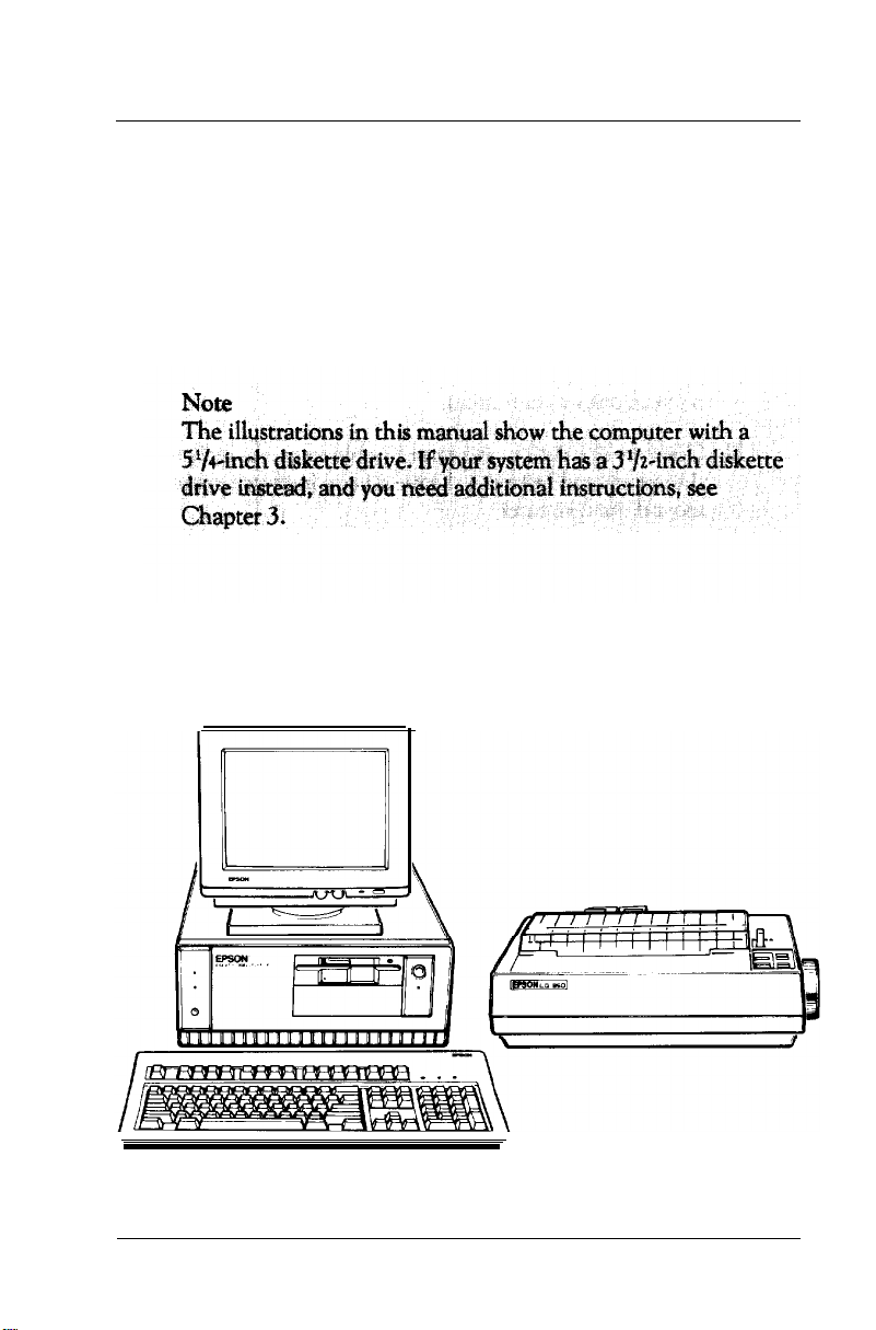
Chapter 1 provides simple step-by-step instructions for setting
up your system. On the back cover foldout are illustrations
showing the different parts of your computer; refer to these as
you set up your system.
Introduction 3
Page 18

Chapter 2 describes how to run the Setup program to define
your computer’s configuration. Do this before you use your
computer. You may need to do it again later if you change the
configuration.
Chapter 3 provides instructions for important operating
procedures, such as using and caring for disks and disk drives.
Chapter 4 describes specialized features you can use to enhance
your system’s performance.
Chapter 5 describes some of the options you can use in your
computer and contains instructions for removing the cover,
setting jumpers, and installing options.
Appendix A provides instructions for using the VGA device
drivers and utilities.
Appendix B explains how to install and remove a hard disk or
diskette drive.
Appendix C describes how to perform a hardware-level format
on a hard disk. You need to do this only if you have installed a
new hard disk that has never received this type of low-level
format, or if you are having serious problems with the disk.
Appendix D contains troubleshooting tips.
Appendix E outlines the system diagnostics checks. If you are
having trouble with any part of the hardware, you may want to
run some of these.
Appendix F gives the technical specifications for the computer.
At the end of the manual, you’ll find a glossary and an index.
4 Introduction
Page 19

Where to Get Help
Customer support and service for Epson products are provided
by a network of authorized Epson dealers and Customer Care
Centers throughout the United States. Epson America provides
product information and support to its dealers and Customer
Care Centers.
Therefore, we ask that you contact the business where you
purchased your Epson product to request assistance. If the people
there do not have the answer to your question, they can obtain
it through our toll-free dealer support program. Epson is
confident that this policy will provide you with the assistance
you need.
Call the Epson Consumer Information Center at
(213) 782-2600 for the following:
❏ Your nearest Epson dealer
❏
The nearest Customer Care Center.
To locate or purchase accessories or supplies, contact your
nearest Epson dealer.
Page 20

6 lntroduction
Page 21
Chapter
1
Setting Up Your System
Setting up your Equity 386/25 PLUS personal computer is easy.
Just follow the eight steps in this chapter. As you set up your
computer, you may want to leave this manual’s back cover
foldout open so you can refer to the illustrations identifying the
different parts.
Choosing a Location
1
Setting Up Your System
1-1
Page 22

Before you set up your computer, it’s important to choose a safe,
convenient location that provides the following:
❏ A large, sturdy desk or table. The surface should be strong
enough to support the weight of your system and all of its
components. Select a location that allows plenty of space so
you can work comfortably.
❏ A flat, hard surface. Soft surfaces like beds and carpeted
floors attract static electricity, which can erase data on your
disks and damage the computer’s circuitry. Soft surfaces also
prevent proper ventilation.
❏ Good air circulation. Air must be able to move freely under
the system and behind it. Leave several inches of space
around the computer.
Moderate environmental conditions. Protect your computer
❏
from extremes in temperature, humidity, dust, and smoke.
Avoid direct sunlight or any other source of heat. High
humidity also hinders operation, so select a cool, dry area.
Appropriate power sources. To prevent static charges,
❏
connect all your equipment to three-prong, 120-volt
grounded outlets. You need one outlet for the computer, one
for the monitor, and additional outlets for a printer and any
other peripherals.
No electromagnetic interference. Locate your system away
❏
from any electrical device, such as a telephone, which
generates an electromagnetic field.
Setting Up Your System
1-2
Page 23
Removing the Protector Card
2
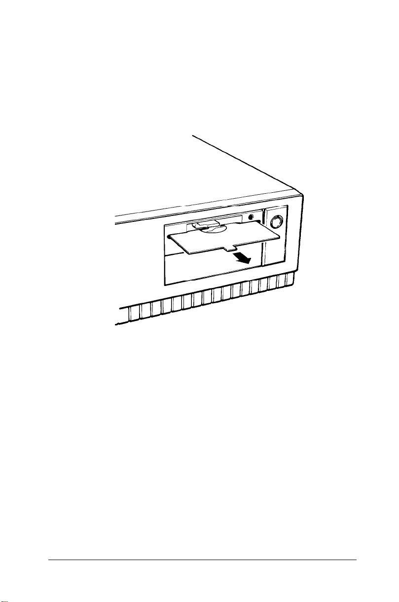
If you have a 5¼-inch diskette drive, there is a protector card in
the diskette slot. This card is inserted at the factory to protect
the read/write heads in the drive. To remove it, flip the latch up
to pop the card out part way, then pull it out, as shown below.
(If you have a second 5¼-inch diskette drive, be sure to remove
the protector card from that drive as well.)
Save the protector card. If you transport your computer, you may
want to insert the card into your diskette drive prior to shipping.
This will protect the read/write heads during the shipping
process.
Setting Up Your System
1-3
Page 24

Connecting a Monitor
3
The procedure you use to connect your monitor to the computer
depends on the type of monitor you have. If you have a VGA
monitor (or a multi-frequency monitor with an analog
connector), you can connect it to the computer’s built-in VGA
port. See “Using the VGA Interface” below. If you have any
other type of monitor, see “Using a Display Adapter Card”
below.
Using the VGA Interface
Follow these steps to connect your VGA monitor to the VGA
port on the computer:
1.
Make sure your monitor is turned off.
2.
Place your monitor on top of or near the computer. For easy
access, turn the monitor and computer around so the backs
of both components are facing you.
3.
If necessary, connect the monitor cable to the monitor.
(Your monitor may have a permanently attached cable.)
Setting Up Your System
1-4
Page 25
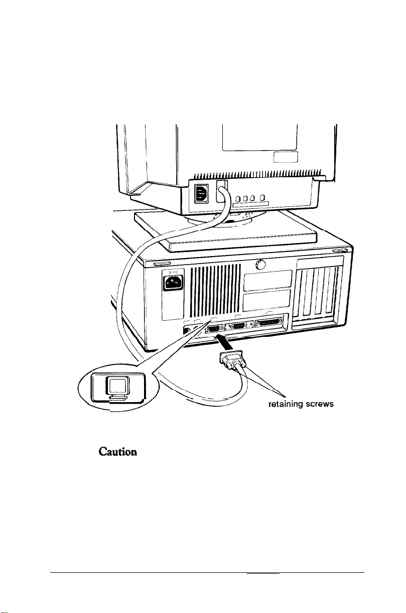
4.
Examine the connector end of the monitor cable, and
position the plug to match the orientation of the monitor
interface (marked with a monitor icon). Then insert the
plug into the port (the connector should fit in easily when
properly oriented), as shown below.
To avoid damaging the connector, take care not to bend
the pins when inserting the plug.
5.
If the connector has retaining screws, tighten them by hand
or with a screwdriver, depending on the screw type.
Setting Up Your System
1-5
Page 26
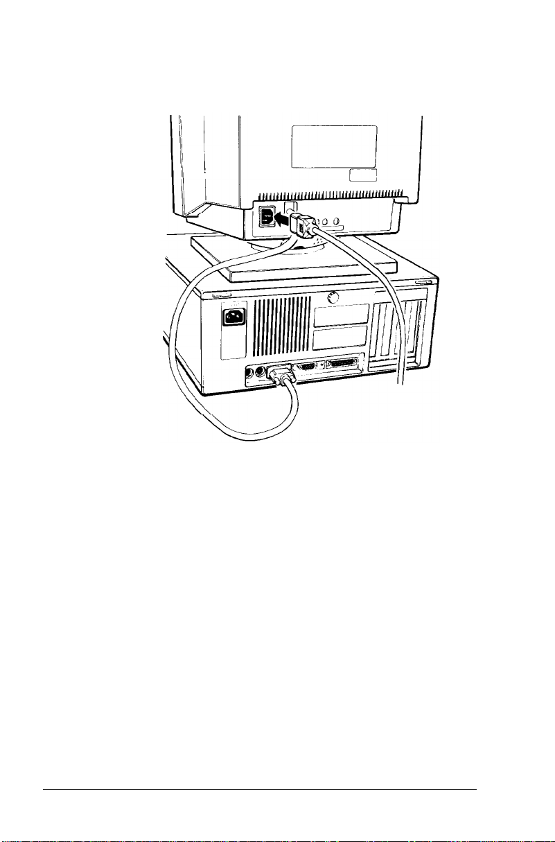
6.
Plug the monitor power cord into the monitor’s power inlet,
as shown below.
7.
Plug the other end of the power cord into an electrical
outlet.
l-6
Setting Up Your System
Page 27
Using a Display Adapter Card
If you are using a non-VGA monitor, you’ll need to install a
display adapter (video) card in one of the computer’s option
slots before you can connect the monitor. (Your dealer may have
already installed the video card for you.)
If the video card has not yet been installed, you’ll need to follow
the step-by-step instructions in Chapter 5 to install an option
card. But first, check the following table to make sure your
display adapter card and monitor are properly matched.
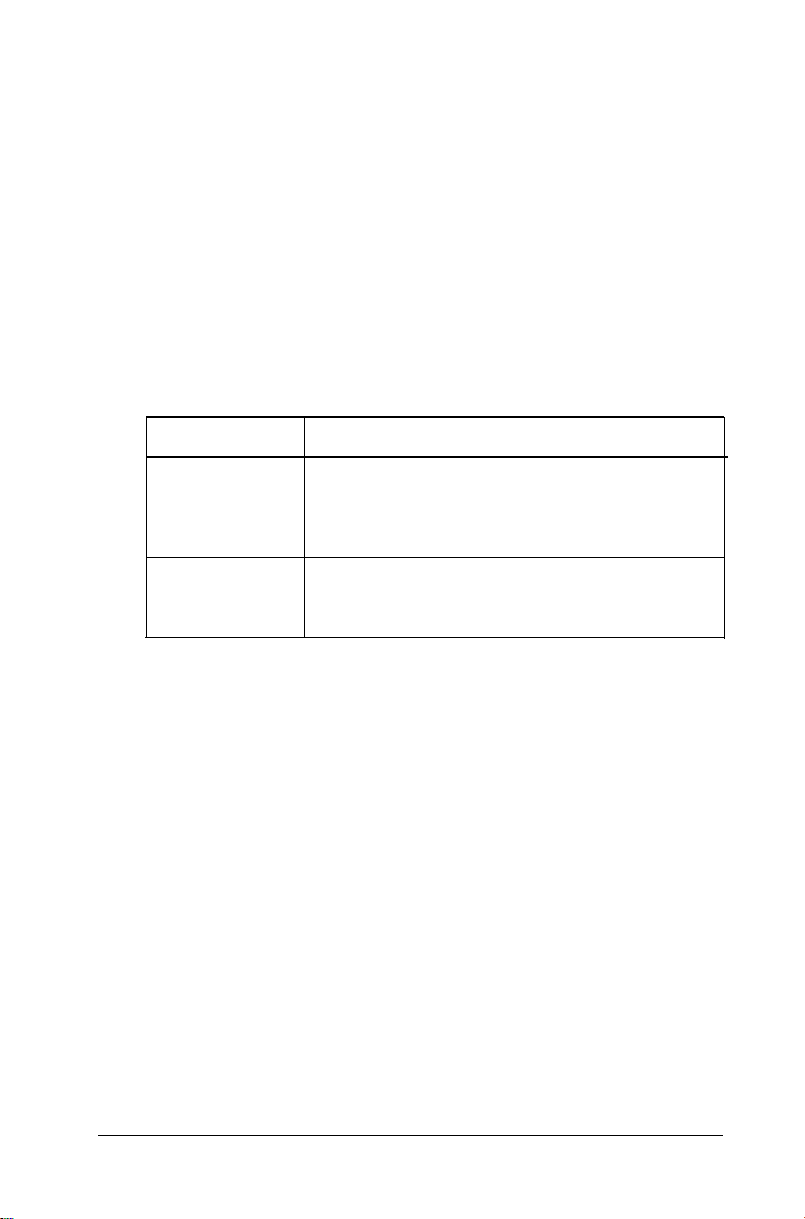
Monitor/video card compatibility
Monitor
Monochrome
Color or EGA
* Color monitors do not support EGA cards.
Video card
Monochrome display adapter (MDA)
Multi-mode graphics adapter (MGA)
Enhanced graphics adapter (EGA)
Hercules® graphics card
Color graphics adapter (CGA)
Multi-mode graphics adapter (MGA)
Enhanced graphics adapter (EGA)
When you are installing the video card, check to make sure any
switches or jumpers on the card are set properly. For example,
you may need to change a switch setting to select color or
monochrome. See the documentation that came with your
monitor or video card for instructions.
Setting Up Your System
1-7
Page 28

Once you have installed your video card, return to this section
to connect your monitor to the computer. If your monitor came
with its own manual, follow the instructions there. Otherwise,
you can follow the steps in “Using the VGA Interface” above;
just insert your monitor connector into the video card port
instead of the built-in VGA port.
Connecting a Printer or Other Device
4
Your computer has both parallel and serial interfaces. To
connect a printer or other peripheral device to one of these
interfaces, follow the instructions below. Of course, Epson offers
a full range of printers; ask your dealer for more information.
Using the Parallel Interface
The parallel interface on your computer is Centronics®
compatible and uses a DB-25S connector.
To connect your printer and computer, you need an IBM
compatible printer cable. If you are not sure which one you
need, check with your Epson dealer.
1-8
Setting Up Your System
Page 29
Once you have the correct printer cable, follow these steps:
1.
Place the printer next to the computer with the back panels
of both components facing you.
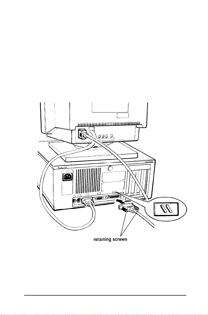
2.
One end of the printer cable has a 25pin, D-shell
connector. Position the plug to match the orientation of
the parallel interface (marked with a special icon). Then
insert the connector into the port, as shown below. If the
plug has retaining screws, tighten them by hand or with a
screwdriver, depending on the screw type.
Setting Up Your System
1-9
Page 30
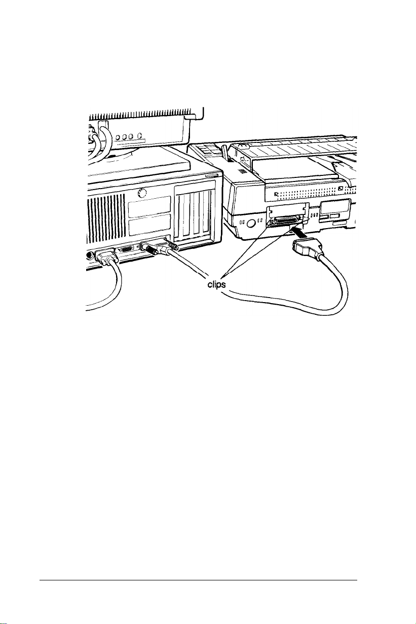
3.
Connect the other end of the cable to the printer, as shown
below. To secure the cable, squeeze the clips at each side of
the printer port and push them into place.
1-10
4.
Plug the printer’s power cord into a three-prong, 120-volt,
grounded electrical outlet.
Setting Up Your System
Page 31
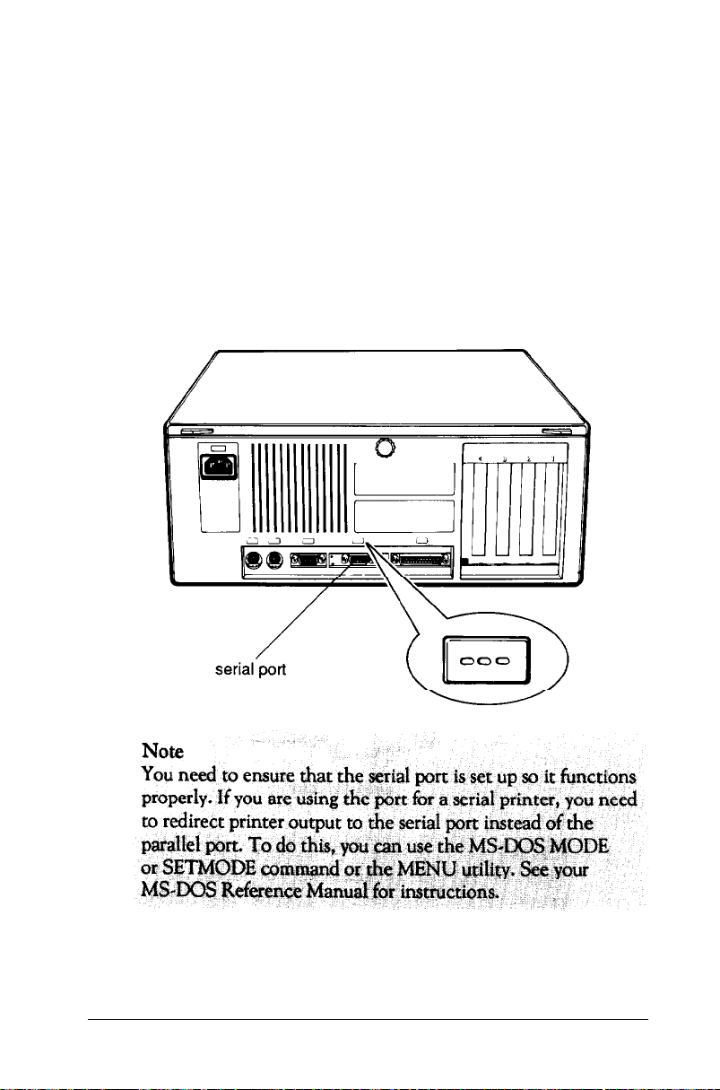
Using the Serial Interface
If you have a printer, a modem, or other peripheral with a serial
interface, you can connect it to the serial (RS-232C) port on
the back of the computer.
The serial port uses a DB-9P connector, so be sure you have a
compatible cable. To connect a serial device, follow the same
steps as above for connecting a parallel device but insert the
connector into the serial port, marked with a special icon, as
shown below.
Setting Up Your System
1-11
Page 32

Connecting the Keyboard
5
Follow these steps to connect the keyboard:
1.
Hold the keyboard cable connector so the arrow indicator
on the housing faces up. Insert the plug into the appropriate
socket, marked with a keyboard icon, as shown below.
Caution
1-12 Setting Up Your System
arrow indicator
Page 33

2.
You can raise the keyboard by adjusting the legs on the
bottom. To change the angle of the keyboard, turn it over
and flip each leg upward until it locks into place, as shown
below.
Connecting the Mouse
6
Your computer has an auxiliary port for an IBM PS/2 compatible
mouse that uses a miniature DIN (6-pin) connector.
If you have purchased a mouse with this type of connector, you
can connect it to the built-in port on your computer. If you have
another kind of mouse that requires a different interface port,
you need to install an option card to provide the interface. You
also need to change the settings of jumpers JP10 and JP11 inside
the computer. See Chapter 5 for instructions, or ask your dealer
for assistance.
To connect a mouse to the built-in mouse port, hold the mouse
plug so it is oriented properly with the computer socket. Insert
the plug into the appropriate socket, marked with a mouse icon,
as shown in the following illustration.
Setting Up Your System
1-13
Page 34

mouse connector
Once you have connected a mouse, you may need to add
commands to your MS-DOS CONFIG.SYS file to enable your
computer to use a mouse. See your MS-DOS Reference Manual
and the manual that came with your mouse for instructions.
1-14 Setting Up Your System
Page 35

Connecting the Power Cord
7
Follow these steps to connect the power cord:
1.
Plug the power cord into the AC power inlet on the back
panel, as shown below.
WARNING
To
avoid an electric shock, be sure to plug the cord into
the computer before plugging it into the wall socket.
2.
Plug the other end of the power cord into a three-prong,
12O-volt, grounded electrical outlet.
Setting Up Your System
1-15
Page 36

Turning On the Computer
8
After you set up your system, you’re ready to turn on the power.
But first, read the following safety rules to avoid accidentally
damaging your computer or injuring yourself:
0 Do not unplug cables from the computer when the power is
on.
❏
Never turn on the computer with a protector card in the
diskette drive.
❏
Never turn off or reset your computer while a disk drive
light is on. This can destroy data stored on disk or make an
entire disk unusable.
❏
Always wait at least five seconds after you turn off the power
before you turn it on again. Turning the power off and on
rapidly can damage the computer’s circuitry.
❏
Do not leave a beverage on top of or next to your system or
any of its components. Spilled liquid can damage the
circuitry of your equipment.
-
❏
Always turn off the power, disconnect the computer’s power
cord, and wait five seconds before you remove the cover.
Only remove the cover to access optional devices or change
jumper settings.
Follow these steps to turn on your system:
1.
Make sure the power cord is plugged into the AC power
inlet on the back panel of the computer and into a three-
prong, 120-volt, grounded electrical outlet.
2.
Turn your computer around so the front panel faces you and
place your other system components in an arrangement that
suits you. (See step 1, “Choosing a Location,” for a typical
arrangement.)
1-16
Setting Up Your System
Page 37

Turn on the monitor, printer, and any other peripheral
3.
devices connected to the computer.
To turn on the computer, press the power button located on
4.
the right side of the front panel, as shown below.
The power indicator below the button lights up. After a few
seconds, the computer starts to perform a diagnostic self test-a
series of checks it completes each time you turn it on to make
sure everything is working correctly.
Note
If you or your dealer have made a major change to your
system, such as adding a disk drive, you may need to wait as
long as five minutes for your computer to complete power-on
diagnostics the first time you turn it on. The more extensive
the changes are, the longer the diagnostics take.
Setting Up Your System
1-17
Page 38

When the system has successfully completed its self test, you see
a prompt to insert a system diskette. (Do not insert a diskette at
this point.)
If necessary, use the controls on your monitor to adjust the
brightness and contrast until characters on the screen are clear
and at a comfortable level of intensity. If your monitor has
horizontal and vertical hold controls, you may need to use them
to stabilize the display.
Turning
Off the
When you are ready to turn off your system, reverse the
sequence of steps you followed to turn it on. Turn off the
computer first, then turn off the monitor and any peripherals.
Now go on to Chapter 2 and follow the instructions to run the
Setup program.
Computer
1-18
Setting Up Your System
Page 39

Chapter 2
Running the Setup Program
The first time you use your Equity 386/25 PLUS, you need to
run the Setup program on the Reference diskette to define the
computer’s configuration. This is a simple procedure you must
do at least once. (You may need to do it again later, if you
change the configuration.)
The Setup program automatically configures parts of your system
and lets you set (or change) the following for your computer:
❏ Display adapter type
❏ Power-on password
❏ Extended memory caching
❏ Processor speed
❏
Keyboard and speaker options
❏ Real-time clock’s time and date
❏
Hard disk drive configuration
❏ Diskette drive type(s)
❏
Serial and parallel port settings.
The configuration you define with the Setup program is stored
in the computer’s CMOS RAM, which is backed up by a
battery. Whenever you turn on the computer, it searches the
CMOS RAM for the correct installation information. If the
computer discovers a difference between the information in the
CMOS RAM and its actual configuration, it prompts you to run
the Setup program.
Running the Setup Program
2-1
Page 40

Automatic Configuration
The Equity 386/25 PLUS automatically defines your system’s
memory configuration and recognizes a math coprocessor, if you
have installed one. It also detects and configures most of the
devices you have installed in your system. For this reason, you
may not need to change any of the default settings in the Setup
program. However, you should check each of the options on the
Setup menu to verify that the settings are correct for your
configuration.
The computer automatically configures the 2MB of memory that
comes with your system as 640KB of base memory and 1024KB
of extended memory. If you install even more memory, Setup
configures it as extended memory also.
Starting the Setup Program
Follow these steps to start the Setup program:
1.
Make sure your computer is turned off.
2.
Insert the Reference diskette in drive A as shown in the
following illustration. Make sure the label is facing up and
the read/write slot is pointed toward the drive.
2-2
Running the Setup Program
Page 41

Slide the diskette into the drive until it is in all the way.
Then turn the latch down to lock it in a vertical position.
(For more instructions on inserting and removing diskettes,
including 3½-inch diskettes, see Chapter 3.)
3.
Turn on your system. (Remember to turn on your monitor
and any peripherals before you turn on the computer.) The
screen displays the Operation Menu:
If an error message appears when you turn on the computer,
see “Continuing From an Error Message,” below.
Running the Setup Program
2-3
Page 42
4.
The Setup option is highlighted. To select it, press
Enter. The screen displays the main Setup menu:
Exit
Display
Password
Cache memory
Processor speed
Keyboard / Sound
Real-time clock
Hard disk drive
Diskette drive
Serial/Parallel
Continuing From an Error Message
If your computer has never been set up, you may see an error
message, such as the following:
162 - System options not set
(Run SETUP in REFERENCE DISK)
(Resume = "Fl" key)
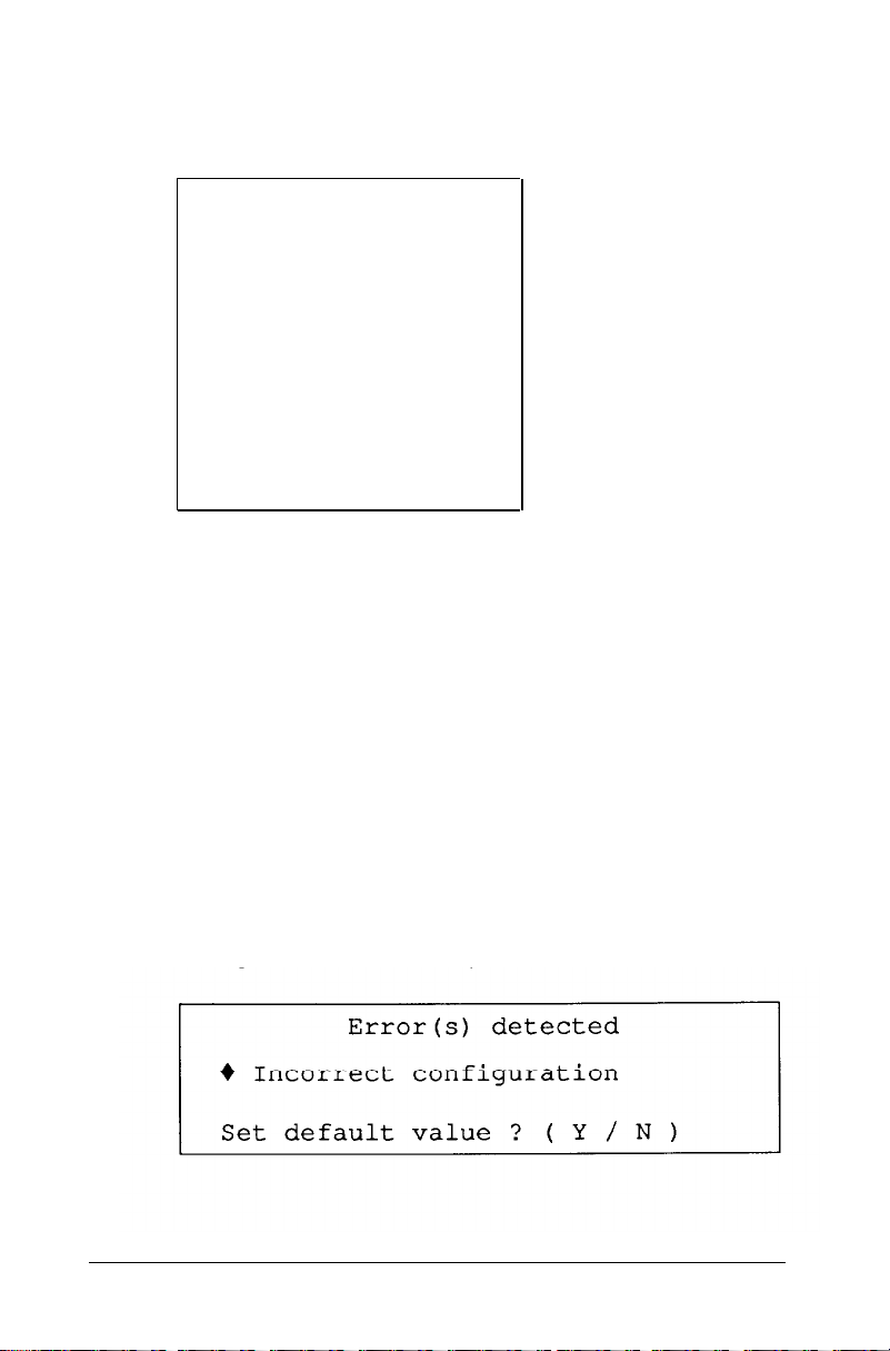
If you see an error message like this one, follow these steps:
1.
Press F1. The computer beeps and the screen displays a
message, such as the following:
2-4 Running the Setup Program
Page 43

The error message beside the diamond indicates the
condition causing the error. There may be more than one
error listed in the message. Here are some of the error
messages you may see:
Time is invalid
HDD and/or HDC failed initialization
Memory size is incorrect, correction made
Cacheable range is adjusted
Incorrect configuration
Checksum is incorrect
HDD is incorrect
Some errors, such as Time is invalid, do not allow
you to set a default value, so the screen does not display the
Set default value prompt.Ifyou see one of these
errors, press ESC; the screen displays the main Setup menu
so you can enter a new setting.
2.
Be sure Y is highlighted and press
changes the setting that caused the error to a setting that is
more likely to match your configuration. The screen displays
the main Setup menu:
Enter.
The Setup program
Exit
Display
Password
Cache memory
Processor speed
Keyboard / Sound
Real-time clock
Hard disk drive
Diskette
drive
Serial/Parallel
Running the Setup Program
2-5
Page 44

You should check all the settings in the Setup program to
make sure they are correct for your system. The default value
for the setting that caused the error may not be the correct
one for your configuration.
Moving the Cursor Block
Use and to move the cursor block (the highlighted bar)
through the options on the main Setup menu. After you
highlight the option you want, press Enter to select it.
Follow the instructions in the rest of this chapter to use the
Setup program to define your computer’s configuration.
2-6
Running the Setup Program
Page 45

Setting the Display Adapter Type
The Setup program can usually detect the exact type of display
adapter you are using with your computer. If you have connected
a VGA monitor to the built-in VGA port, the Setup program
automatically sets the display adapter type. (With this option
you select the type of display adapter you are using-not the
type of monitor.) If you have installed a display adapter card-or
you just want to check the display adapter setting-follow these
steps.
1.
At the main Setup menu, highlight Display. A submenu
appears identifying the current display adapter type, such as
the following:
VGA
If the display adapter type is correct for your system, you can
skip this section.
Running the Setup Program
I
2-7
Page 46

2.
To change the display adapter setting, press Enter. The
cursor block moves into the submenu and you see an
additional menu on the right side:
CGA
CGA
40 column
80 column
Monochrome 80 column
EGA,MCGA,VGA or other
3.
Press Enter to move the cursor block into this submenu and
then use or to highlight the option that matches your
display adapter type. If you are not sure which one to
choose, follow these guidelines:
If you are using the built-in VGA adapter or have
❏
installed a VGA, EGA, or MCGA card, select EGA,
MCGA,VGA or other.
If you have a color graphics adapter (CGA) or a multi-
❏
mode graphics adapter (MGA) attached to an RGB
(color) monitor, select CGA 80 column. (Also set
the color/mono switch on the MGA card to color.)
If you have a composite color monitor, such as a color
❏
television with a video input, try selecting CGA 80
column. If the resulting resolution is poor, run Setup
again and select CGA 40 column.
If you have a monochrome display adapter (MDA), an
❏
MGA, or a Hercules MGA attached to a monochrome
monitor, choose Monochrome 80 column.
(Also set the color/mono switch on the MGA card to
mono.)
If you have any other combination of monitor and
❏
display adapter card, select
o t he r. In addition, consult the documentation
supplied with your display adapter card.
2-8 Running the Setup Program
EGA, MCGA, VGA or
Page 47

Note
4.
After you highlight the appropriate display adapter type,
press Enter. The screen displays your new setting.
5. Highlight
to return to the main Setup menu.
* * * SAVE SETTING
* * * and
Setting the Power-on Password
A power-on password is a feature that lets you control who can
access your system. However, you do not need to set a power-on
password to use your computer. If you do not want to set a
password, skip this section.
Once you set a power-on password, you must enter it at the key
prompt ( ) every time you turn on or reset your computer.
If you cannot enter it correctly, the computer does not respond
to your keyboard entries. Therefore, if you set a power-on
password, be sure to remember it or write it down and keep it in
a safe place.
If you want to use your computer as a network server, you can
set your password to operate in network server mode. (See
“Using Your Computer as a Network Server” in Chapter 4 for
more information.)
press
Enter
Running the Setup Program
2-9
Page 48

Follow these steps to set a power-on password and turn on
network server mode (if necessary):
At the main Setup menu, highlight Password. This
1.
submenu appears:
Power-on password
Network server mode OFF
Press Enter. The cursor block moves to power-on
2.
password.
3.
Press Enter. The cursor block moves to an empty box:
2- 10
4.
To enter a password, type any combination of characters
(including letters, numbers, and blank spaces) up to a total
of seven characters. You can use the backspace key to delete
mistakes.
Do not use characters requiring the Shift key, such as
$, @ , or *
recognize the Shift key when you use your password to
access the system.
Running the Setup Program
in your password. The computer does not
Page 49

If you want to return to the password submenu without
saving any changes, press Esc.
5.
After you enter a password, press Enter to return to the
password submenu.
6.
If you want to change the network server mode setting,
highlight Network server mode . To turn network
server mode on or
You must set a power-on password to turn on network server
mode. If you did not yet enter a password, this message
appears:
off,
press
Enter.
Set a power-on password first
To enter a password, highlight Power-on password
and follow steps 3 through 5 above.
7.
After you enter a power-on password and turn network
server mode on or off, highlight
SETTINGS
Setup menu.
* * * * and press Enter to return to the main
* * * *
SAVE
Running the Setup Program
2-11
Page 50

Setting the Extended Memory Caching
Extended memory caching allows your system to work much
faster. When you cache portions of memory, the computer copies
information from that memory into a high-speed cache buffer.
Your system can find information more quickly in the cache
buffer than when it looks for it in the system memory. This
greatly improves the speed at which your system performs.
Note
Caching is active
25 MHz (high) speed.
The Equity 386/25 PLUS automatically enables memory
caching for the 640KB of base memory in your system. For the
memory above 1MB, the Setup program allows you to turn
extended memory caching on or off. The default setting is ON
for all the extended memory currently installed in your system
from 1MB up to the maximum.
Most of the time, you should cache all of your extended memory
to maximize the performance of your 32-bit computer. However,
if you install an optional memory card that “shares” memory
with any of your other system memory, you should turn caching
off in memory areas that are shared. See the manual that came
with your memory card to see if this is necessary.
only when your computer is operating at
To check or change the extended memory cache setting, follow
these steps:
1. At the main Setup menu, highlight Cache memory.
You see the following cache memory table:
2-12
Running the Setup Program
Page 51

The table indicates the range of extended memory currently
installed in your system. You see ON or OFF
area because your system comes with 2MB of memory and
the extended memory area from 1MB to 2MB can be
cached. If you installed additional memory, you see ON or
OFF for
installed. The shaded areas indicate ranges of memory that
are not installed.
If your extended memory cache setting is correct, you can
skip the rest of this section.
2.
To change the setting, press Enter. The cursor block moves
each additional megabyte of memory you have
in
to Extended memory caching.
3.
Press Enter again. The cursor block moves to the first range
in the cache table. To change the setting for
from
ON
to
OFF
or vice versa, press
4.
If you installed memory above 2MB, press to move the
cursor block to the next range. Press Enter to change the
setting from
Then press or to move to the other ranges and press
ON
to
OFF,
if necessary.
the first range
Enter.
Enter, as necessary, to change the settings.
the first
5.
When you are finished, press to move the cursor block to
the submenu.
6. Highlight * * * SAVE SETTING * * * and press Enter
to return to the Setup menu.
Running the Setup Program
2-13
Page 52

Setting the Processor Speed
Your computer’s processor can operate at two speeds: high or
low. High speed is 25 MHz and low speed simulates 8 MHz. The
processor is set to operate at high speed (where it can access
memory faster) unless you change it to low or set the speed to
change automatically (when necessary).
When the computer is running at high speed, the TURBO
indicator on the front panel is illuminated.
You should use high speed for almost everything you do since
your programs work faster on high speed. However, certain
application programs have specific timing requirements for
diskette access and can run only at a slower speed; check your
application program manual.
When you set the processor to change speed automatically, the
computer switches to low whenever it needs to access a diskette
drive and runs at high for all other operations.
This section describes how to set the processor speed in the
Setup program. You can also change the speed using keyboard
commands or by running the ESPEED program. See “Changing
the Processor Speed” in Chapter 4 for more details.
Follow these steps to set your processor speed:
1.
At the main Setup menu, highlight Processor
speed
. The current status appears:
Speed: High
2- 14
Running the Setup Program
Page 53

If the displayed setting is correct, skip this section,
2.
To change the processor speed, press Enter. The cursor
moves into the submenu and you see another menu:
(High is
25 MHz,
Low simulates
8 MHz, and
Automat i c tells the computer to switch from high to
low when accessing a diskette drive.)
3.
Press Enter to move the cursor block into the option menu.
4.
Use or to highlight the speed you want and press Enter.
5. Highlight ** SAVE SETTING * * and press Enter
to return to the main Setup menu.
Setting the Keyboard and Speaker Options
The Keyboard/Sound option lets you control these three features
in your computer:
❏ Speaker
❏
Initial num lock mode
❏ Keyboard repeat rate.
Your computer has a built-in speaker that beeps when you
perform certain operations. The default
(on) since it serves a useful purpose in many applications;
however, you may prefer to disable the speaker.
setting is Enabled
Running the Setup Program
2-15
Page 54

When num lock mode is on, you can use the numeric keys on
the keypad to enter numbers. The initial num lock option in the
Setup program determines whether num lock is on or off when
you turn on your computer.
To turn num lock mode off, just press Num Lock. The
Num Lock light (on the keyboard) goes out and num lock is
disabled until you turn the computer off or until you press
Num Lock again. The next time you turn on your computer,
num lock returns to the setting you selected in the Setup
program.
Note
If you are using the keyboard that came with your computer
(or another IBM AT compatible keyboard), the default for
the initial num lock setting is
ON. If
you are using a keyboard
that has 83 or 84 keys, the initial num lock default setting is
OFF.
The keyboard repeat rate option lets you change the speed at
which your keyboard repeats a character when you hold down a
key. The default setting
faster or slower.
is Normal,
but you can make the rate
Follow these steps to check or change the keyboard and speaker
options:
At the main Setup menu, highlight Keyboard/ Sound.
1.
The current settings appear:
Speaker
Enabled
Initial num lock
Normal
2- 16
KB repeat rate
If the displayed settings are appropriate for you, skip this
section.
Running the Setup Program
ON
Page 55

2.
To change any of the settings, press
moves into the submenu and the Speaker option is
highlighted.
3.
To enable or disable the speaker (turn it on or off), press
Enter.
The cursor
Enter.
To turn the initial num lock setting on or off, highlight
4.
Initial num lock and press
5.
To change the keyboard repeat rate, highlight
KB repeat rate.
6.
Press Enter to move the cursor block into the menu.
Use or to highlight the speed you want and press Enter.
7.
8.
Highlight
*** SAVE SETTINGS * * * and press
You
see the following option menu:
Enter.
Enter to return to the main Setup menu.
block
Setting the Real-time Clock
The real-time clock in your computer continuously tracks the
time and date-even when the computer is turned off. The first
time you run Setup, use
set
the time and date for your computer. You may need to use
this option
time. The computer automatically changes the date for leap
years.
the Real-time
again later to adjust your clock for daylight savings
Running the Setup Program
clock option to
2-17
Page 56

Follow these steps to set the real-time clock:
1. At the main menu, highlight Real-time
the time and date have been previously set, the current
settings appear:
Time 09:16:52
Date
If the time and date are correct, you can skip the rest of this
section.
If the time and date are incorrect, go to step 2 below.
If the time and date have never been set, the submenu
contains a template for you to fill in:
Time xx:xx:xx
Date xx-xx-xxxx
Press Enter to move the cursor block into the submenu.
2.
To set or change the time, press Enter again. You see this
3.
box:
12-29-1990
clock. If
2-18
(“hh” stands for hours, “mm” stands for minutes, and “ss”
stands for seconds.)
Running the Setup Program
Page 57

4.
Using a 24-hour clock, enter the time in the exact format
shown in the box. Type two digits for each part; the Setup
program automatically inserts the colons ( : ). For example,
to set the time to 1:30 p.m., you would type the following:
133000
You can use the backspace key to make corrections. When
the time is correct, press Enter. If you enter an invalid
time-for example, a number greater than 23 for the hours
or greater than 59 for the minutes or seconds-the computer
ignores your entry. Try again.
5.
To set or change the date, highlight Date and press
Enter. You
(“mm” stands for month, “dd” stands for day, and “yyyy”
stands for year.)
see this box:
6.
Enter the date in the exact format shown in the box. Use
two digits for the month and day, and four digits for the
year; the Setup program automatically inserts the hyphens.
For example, to set the date for December 29,1990, you
would type the following:
12291990
You can use the backspace key to make corrections. When
the date is correct, press Enter. If you enter an invalid
date-for example, a number greater than 12 for the month
or greater than the number of days in that month-the
computer ignores your entry. Try again.
7.
Press once or twice to return to the main Setup menu.
Running the Setup Program
2-19
Page 58
Note
The Setup program automatically saves the time and date
when
you
press
Enter
after typing each one. If you then exit
the Setup program without saving your changes, the new time
and date still take effect.
Setting the Hard Disk Drive Configuration
If your computer came with a factory-installed hard disk, your
hard disk configuration has already been set and you can skip
this section.
If you installed or removed a hard disk, follow these steps to set
the computer’s hard disk configuration:
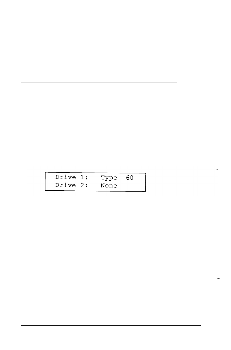
1. At the main menu, highlight Hard disk drive.
Your current settings appear, such as the following:
2-20
The Type number indicates the type of hard disk
installed in your computer. See your hard disk
documentation for the correct drive type number. (If that
documentation does not give the drive type number, it may
list the drive’s parameters which you can use to identify the
drive type number.) Then consult the Hard Disk Drive
Types table on page 2-24 for a list of the types you can use in
your computer.
The None after Drive 2 indicates that there is no
second hard disk.
If the displayed settings match your hard disk configuration,
skip the rest of this section.
Running the Setup Program
Page 59
If a setting is incorrect, or if you want to see more details
about your hard disk configuration, go to step 2.
2.
Press
Enter. You
The submenu lists the settings you can change for each drive:
the number of cylinders, the number of read/write heads, the
number of sectors, the precompensation cylinder, and the
landing zone (the cylinder on which you park the heads
when moving the computer). It also displays the total storage
capacity in megabytes.
3.
If you want to change the settings for drive 1 (which is
drive C on most computers), press Enter to highlight
Drive 1:.
press Enter and then to highlight Drive
see a menu such as the following:
If you want to change the settings for drive 2,
2:.
4.
Press
Enter
again. You see this submenu:
Running the Setup Program
2-21
Page 60

5.
If you have disconnected the drive or if the drive does not
exist, highlight None and press Enter. All the drive
settings become 0. Go to step 8.
If your hard disk matches one of the drive types listed in the
Hard Disk Drive Types table, go to step 6.
If your hard disk does not match one of the drive types listed
in the Hard Disk Drive Types table, go to step 7.
6.
Highlight Type and press Enter. The current type
number appears:
Now select the drive type number that matches your hard
disk configuration in the Hard Disk Drive Types table.
You can enter the drive type in one of two ways:
❏
You can type the drive type number and press Enter.
The screen displays the new number and settings.
2-22
❏
You can use the cursor keys to scan through the drive
type numbers. This is a handy way to verify new hard
disk settings before you press Enter because the settings
list is updated as you display each new type.
After you select the appropriate drive type number, press
Enter. The screen displays the new number and hard disk
settings. Go to step 8.
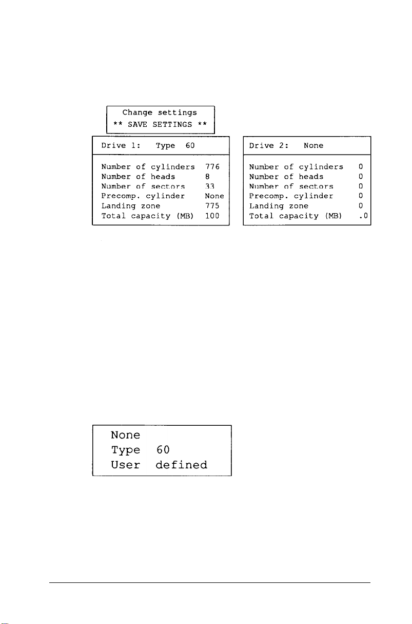
7.
If the configuration of the hard disk does not match one of
the drive types listed in the Hard Disk Drive Types table,
highlight User defined and press Enter. You see the
following:
Running the Setup Program
Page 61

The same parameter is highlighted on the submenu above.
Enter the correct number of cylinders and press Enter.
The information for Number of cylinders is
automatically updated on the submenu above and you see
the next parameter, Number of heads. Enter the
correct number of read/write heads for the hard disk and
press
Enter.
Follow this same procedure for each remaining item in the
settings list (the number of sectors, the precompensation
cylinder, and the landing zone).
If you enter a parameter incorrectly, press or to
highlight the parameter and then enter it again.
The Setup program does not allow you to enter the total
storage capacity; it calculates the storage capacity for you
based on what you enter for the number of cylinders, heads,
and sectors.
After you type the landing zone number and press Enter,
the cursor block returns to the Drive submenu heading.
8.
If you want to change the hard disk type for another drive,
press or and return to step 4.
9.
When the hard disk drive settings are correct, press to
move the cursor block into the top submenu. Highlight
** SAVE SETTINGS
hard disk drive configuration.
* * and press Enter to save your
Running the Setup Program
2-23
Page 62
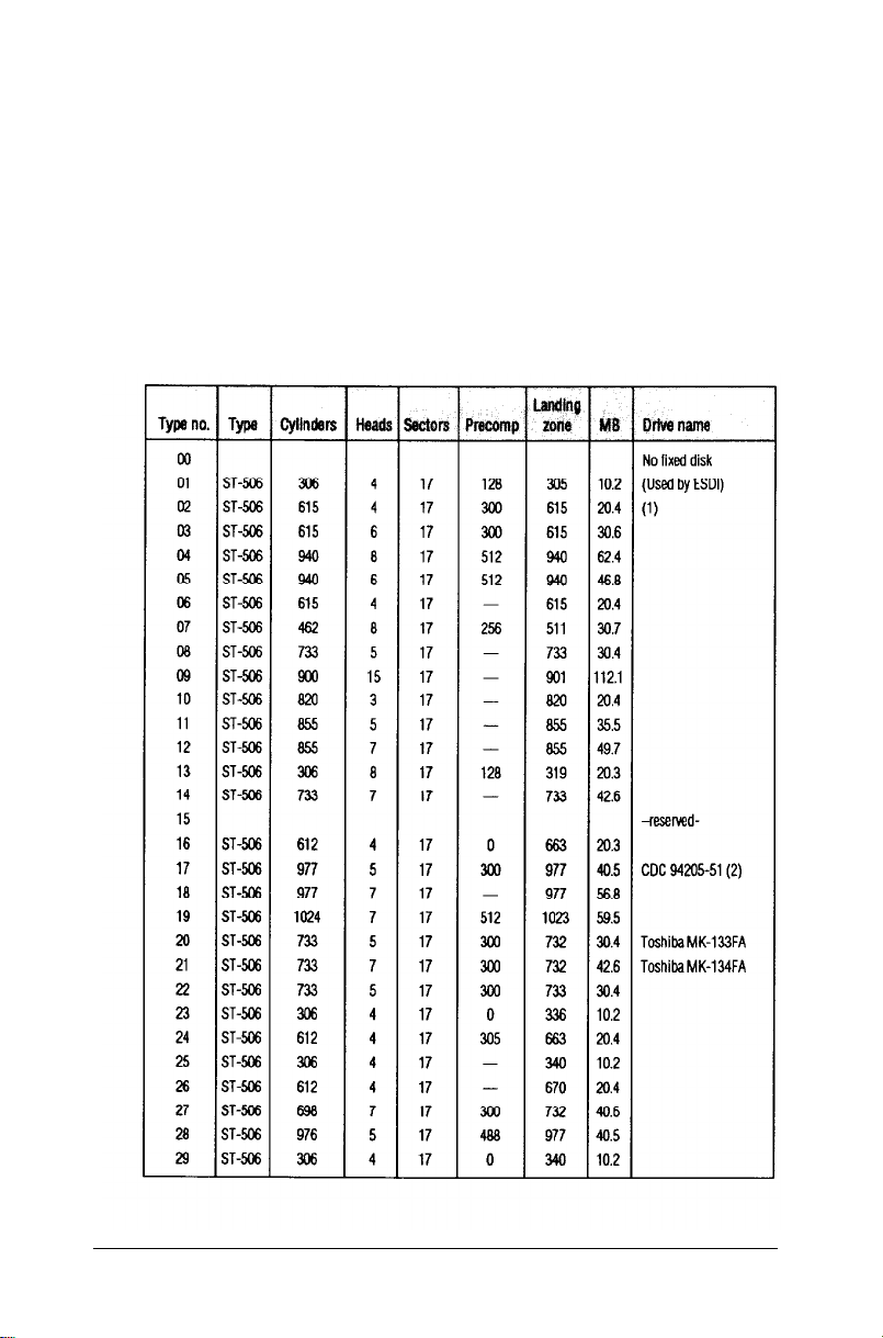
Hard Disk Drive Types
The following table lists the types of hard disk drives you can use
in your computer. Check this table and the documentation
supplied with your hard disk to find the correct number for the
type of hard disk drive(s) installed in your computer. You need
to enter this number when you set the hard disk drive
configuration in the Setup program.
Hard disk drive type
2-24
Running the Setup Program
Page 63
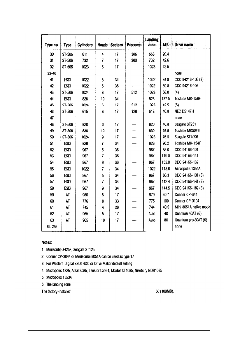
Hard disk drive types (continued)
Running the Setup Program
2-25
Page 64

Setting the Diskette Drive Type(s)
Your Equity 386/25 PLUS probably came with one factory-
installed diskette drive. If you added a second diskette drive or
removed one, you may need to change the diskette drive settings
to match your configuration. If you haven’t made any changes,
you can verify your drive type settings. Follow these steps:
1. At the main menu, highlight Diskette drive.The
current settings appear:
Drive A: 1.2 MB
Drive B:
If the diskette drive types on the screen match your diskette
drive configuration, you can skip the rest of this section.
2.
To change a setting, press Enter. The cursor block moves
into the diskette drive submenu and you see the following:
None
2-26
Not
installed
360 KB drive
720 KB drive (3.5")
1.2 MB drive
1.44 MB drive (3.5")
You also see the
is ON. This tells you that the light on the diskette drive
currently selected is on.
3.
If you want to change the drive A settings, be sure
message
Selected drive light
Drive A: is highlighted and press Enter. If you want to
change the drive B settings, highlight Drive B : and
press Enter. The cursor block moves into the submenu.
Running the Setup Program
Page 65

e
4.
Use or to highlight th
drive and press Enter. The screen displays the type you
selected.
If you want to enter the type for another diskette drive,
return to step 3.
5.
When the diskette drive settings are correct, highlight
** SAVE SETTINGS
block returns to the main Setup menu and you see the
updated information for drives A and B.
correct capacity for your diskette
* * and press Enter. The cursor
Setting the Serial/Parallel Interfaces
The serial and parallel interfaces in your computer are set to act
as the primary ports. If you have not added any additional serial
or parallel port, you can skip this section.
If you install an option card with its own serial or parallel port,
you may want to designate the built-in port as secondary and the
additional port as primary. The Setup program lets you choose
which port is primary and which is secondary so there is no
conflict between the built-in port and the additional port. Here
are some guidelines:
If you install an option card with a port preset as primary by
the manufacturer, you must designate it as the primary port
and make the computer’s built-in port the secondary port.
If you install an option card or peripheral with a port that is
not pre-set, you can designate it as the primary or secondary
port.
If you install two option cards with ports, designate one as
the primary port and the other as the secondary port and
disable the built-in port.
Running the Setup Program
2-27
Page 66

Follow these steps to change your built-in serial and parallel
interface settings:
1. At the main menu, highlight Serial/Parallel.The
current settings for each port appear:
Serial
Parallel
2.
Press Enter to move the cursor block into the submenu. You
see this additional option menu:
Primary
Primary
Disabled
Primary
Secondary
3. If you want to change the serial port setting, be sure
Serial
change the parallel port setting, highlight
and press Enter. The cursor block moves into the submenu.
4.
Use or to highlight the appropriate setting for the port
you selected and press Enter. The screen displays the new
setting.
Note
If you add an option card
highlight
is highlighted and press Enter. If you want to
para11e1
with a parallel or serial port and
a setting that causes a conflict between your
built-in port and the port on the option card, you see- this
message:
2-28
Conflict with option card
Highlight a setting that is appropriate for your system
configuration
Running the Setup Program
and
press
Enter.
Page 67

If you want to change the setting for the other port, return
to step 3.
5.
When the serial and parallel port settings are correct,
highlight ** * SAVE SETTINGS *** and press
Enter. The cursor block returns to the main Setup menu
and you see your updated serial and parallel interface
settings.
Reviewing Your Settings
When you finish using the Setup program to define your
computer’s configuration, use to highlight
Setup menu and press Enter. The following Setup summary
appears on the screen:
Exit at
the
main
Running the Setup Program
2-29
Page 68

There are two more Setup summary screens you need to check.
To display the next screen, press PgDn. You see the following:
Real-time clock
coprocessor not installed
Diskette drive
Speaker Enabled
Initial num lock
Keyboard repeat rate
Serial Primary
Parallel Primary
Time
Date
Drive A:
Drive B:
13:40:38
12-29-1990
1.2 MB
None
Normal
If you have never set the real-time clock, the entry at the top of
the screen flashes to remind you to set the time and date. See
“Setting the Real-time Clock,” above, for instructions.
To view the last Setup summary screen, press
PgDn. You
see
your hard disk drive configuration(s):
Hard disk drive
Drive 1:
Number of cylinders
Number of heads
Number of sectors
Precomp. cylinder None
Landing zone
Total capacity (MB)
Type 60
716
8
33
775
100
2-30 Running the Setup Program
Drive 2:
Number of cylinders 0
Number of heads
Number of sectors
Precomp. cylinder
Landing zone
Total capacity (MB) .0
None
0
0
0
0
Page 69

Check each Setup summary screen to see if all the information is
correct. You can press PgUp to display the previous screen or
PgDn to display the next screen. If anything is incorrect, be sure
Change
main Setup menu appears and you can change the appropriate
settings.
settings
is highlighted and press
Enter.
Leaving the Setup Menu
If you did not change any settings or you want to cancel the
changes you made, highlight Exit without saving at
a Setup summary screen and press Enter. The Operation Menu
appears. (If you changed the time or date, the new setting takes
effect even if you exit the Setup program without saving your
changes.)
If you want to save the settings you entered, highlight
** EXIT AND SAVE * * and press Enter at a Setup
summary screen. The Setup program stores the new settings and
resets the computer using the new configuration. If you have set
a password, you need to enter it at the key prompt. (See “Using
a Power-on Password” in Chapter 3 for instructions.) The
Operation Menu appears.
The
If you have just run Setup for the first time, remove the
Reference diskette from the drive and turn off your system. Then
follow the instructions in your MS-DOS Installation Guide to
install MS-DOS. (If you are using a different operating system,
follow the installation instructions in that manual.)
Once you have installed MS-DOS, you should always boot the
computer from the hard disk or the MS-DOS Startup diskette
when you are finished running Setup. First remove the
Reference diskette from drive A. If you do not have a hard disk,
insert the Startup diskette. Then reset your computer to make
sure it performs all the commands in the CONFIG.SYS and
AUTOEXEC.BAT files.
Running the Setup Program.
2-31
Page 70

If the computer displays an error message while it is starting up,
run the Setup program again and check the setting the error
message indicates. If the computer still displays an error message
after you check your Setup program settings, see Appendix D or
E, or ask your dealer for assistance.
Note
Be sure to make a backup copy of your Reference diskette
after you run the Setup program and install MS-DOS. See
your MS-DOS Reference Manual for instructions on how to
copy diskettes.
2-32
Running the Setup Program
Page 71

Chapter 3
Using Your Computer
This chapter briefly describes the following procedures for using
your computer:
❏
Installing MS-DOS or another operating system
❏
Copying the Reference and Utility diskette files
❏
Using special keys on the keyboard
❏
Stopping a command or program
❏ Resetting the computer
❏
Using a power-on password
❏
Using disks and disk drives.
Installing MS-DOS or Another Operating
System
After you connect the components of your system and run the
Setup program, you must install the operating system on your
computer. If you are installing MS-DOS, follow the instructions
in your MS-DOS Installation Guide. If you are installing
another operating system, such as MS OS/2 or UNIX, see the
manual that comes with that system for instructions on
installing and using it. The instructions in this manual assume
that you are using MS-DOS with your computer.
Note
Be sure to make backup copies of your original operating
system diskettes.
Using Your Computer
3-1
Page 72

Copying the Reference and Utility Files
If you have a hard disk, you’ll probably want to copy some of the
files on your Reference and Utility diskettes to the hard disk.
This allows you to run the programs directly from your hard disk
instead of having to insert a diskette. Use the COPY command
(described in your MS-DOS Reference Manual) to copy the
following files from the Reference diskette to your hard disk:
AFDD.EXE
HDSIT.VER
The Reference diskette also contains files for the Setup program
and the System diagnostics program. However, you should
always run these programs from the Reference diskette in
drive A; so do not copy these files to your hard disk.
The Utility diskettes contain VGA drivers that allow you to
display graphics in certain high-resolution modes. If you want to
use any of these extended modes on your VGA monitor, you’ll
need to copy any VGA files you need to your hard disk as well.
See Appendix A for a list of the VGA drivers and utilities and
instructions for using them.
ESPEED.EXE
ROMBIOS.COM
HDSIT.COM
Note
Be sure to make backup copies of your Reference and Utility
diskettes. See your MS-DOS Reference Manual for
instructions.
3-2
Using Your Computer
Page 73

Special Keys on the Keyboard
Certain keys on your keyboard serve special functions when
your computer is running MS-DOS or application programs.
The keyboard layout is shown below, and special keys are
described in the table.
function keys
A
main character keys
Key functions
Key
Caps Lock
Shift
Ctrl
cursor
keys
Purpose
Moves the cursor one tab to the right in normal
mode and one tab to the left in Shift mode.
Changes the letter keys from lower- to
uppercase; changes back to lowercase when
pressed again. The numeric/symbol keys on
the top row of the keyboard and the symbol
keys in the main part of the keyboard are not
affected.
Produces uppercase characters or the top
symbols on the keys when used with the
main character keys. Produces lowercase
characters when the Caps Lock function is on.
Works with other keys to perform special
(control) functions, such as editing operations
in MS-DOS and various application programs.
numeric
keypad
Using Your Computer
3-3
Page 74
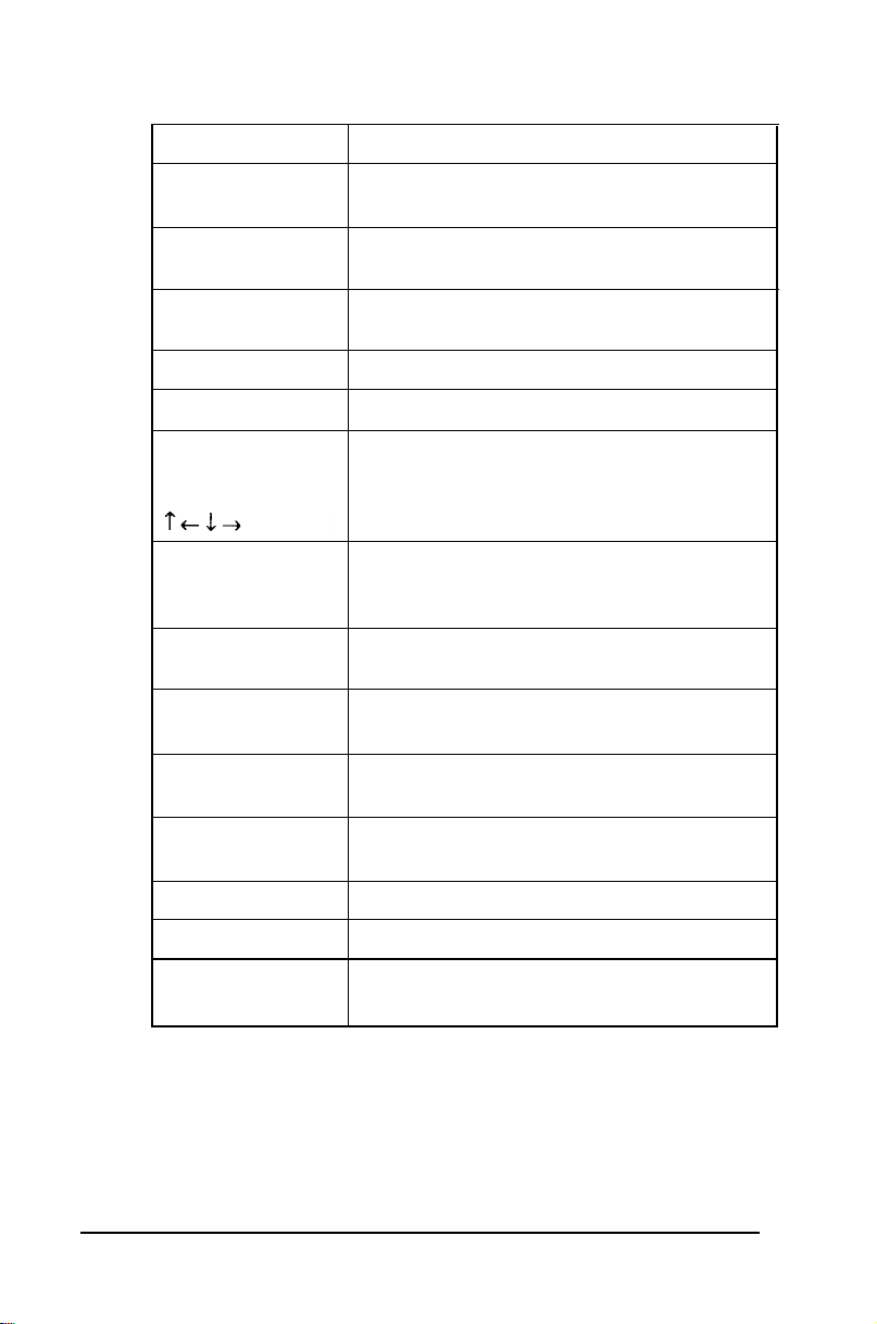
Key functions (continued)
Key
Alt
+-Backspace
J Enter
insert (Ins) Turns the Insert function on and off.
Delete (Del) Deletes the character marked by the cursor.
Home, End
Page UP (PgUp)
Page Down (PgDn)
Num Lock
Esc
F1-F12
Print Screen
(PrtSc)
Purpose
Works with other keys to enter alternate
character codes or functions.
Moves the cursor back one space, deleting
the character to the left of the cursor.
Ends a line of keyboard input or executes a
command.
Control cursor location.
Changes the function of the numeric/cursor
keys from entering numbers to positioning the
cursor; changes back when pressed again.
Cancels the current command line or
operation.
Perform special functions within application
programs.
Prints the screen display on a line printer.
SYS Rq (Req)
Scroll Lock
Pause
Break
The
Caps
Lock,
Num Lock,
toggles; press the key once to turn on a function and again to
turn it off. When the function is enabled, the corresponding
light in the upper right comer of the keyboard is on.
3-4 Using Your Computer
Generates the System Request function in
some application programs (used with Aft).
Controls scrolling in some applications.
Suspends the current operation.
Terminates the current operation (when used
with Ctrl).
and
Scroll
Lock
keys work as
Page 75

Stopping a Command or Program
You may sometimes need to stop a command or program while
it is running. Many programs provide a command you can use
to cancel or even undo an operation. If you have entered an
MS-DOS command that you want to stop, try one of the
following commands:
❏
Hold down the Ctrl key and press C.
❏
Hold down the Ctrl key and press Break.
These methods may also work in your application program.
If not, you may need to reset the computer as described below.
Caution
It is best not to turn off the computer to stop a program or
command. If you created new data and have not yet stored it,
the data will be erased if you turn off the computer. The
computer stores your data in its memory area (RAM) until
you save it; but the data is erased each time you turn off or
reset the computer.
Resetting the Computer
Occasionally, you may want to clear the computer’s current
settings or its memory without turning it off. You can do this by
resetting the computer.
For example, if an error occurs and the computer does not
respond to your keyboard entries, you can reset it to reload
MS-DOS and try again. However, resetting erases any data in
memory that you have not saved; so reset only if necessary.
Using Your Computer
3-5
Page 76

Caution
Do not reset the computer as a means to exit a program.
Some programs classify
program in the normal manner.
without properly exiting a
To reset the computer, MS-DOS must be either on the hard disk
or on a diskette in drive A; so if you do not have a hard disk,
insert the Startup diskette in drive A.
There are two ways to reset the computer:
❏
If you are using MS-DOS, hold down Ctrl and Alt and press
the Del key. The screen goes blank for a moment and then
the computer should reload MS-DOS. If it doesn’t, try the
next method.
❏
Press the RESET button on the front panel. This method
works even when the computer does not respond to your
keyboard entries.
If resetting the computer does not correct the problem, you
probably need to turn it off and reboot it. Remove any
diskette(s) from the diskette drive(s). Turn off the computer
and wait five seconds. If you do not have a hard disk, insert the
Startup diskette in drive A. Then turn on the computer.
and
store new data when you
If you reset the computer
program, you may lose data.
exit a
3-6
Using Your Computer
Page 77

Using a Power-on Password
If you set a power-on password when you ran the Setup program,
you must enter it every time you turn on or reset the computer.
Follow these steps to use your password:
1.
If you do not have a hard disk, insert your Startup diskette
in drive A.
2.
Turn on or reset the computer. The screen displays a key
prompt:
3.
At the key prompt, type your power-on password. The key
turns when you type a character, but the screen does not
display the characters you type. Then press Enter.
After you type the password correctly and press Enter, a happy
face character appears. Then the computer loads MS-DOS and
displays the MS-DOS command prompt. (If you installed the
Shell program when you installed MS-DOS, you see the Shell
Start Programs menu instead of the command prompt.)
Note
If you turned
Setup program,
your password. See “Using Your
Server” in Chapter 4.
You have three chances to enter the correct password. If you do
not enter the correct password at the key prompt, another key
prompt appears. If you do not enter the correct password at the
third key prompt, the screen displays a zero, the keyboard locks
up, and you cannot use the computer. Reset the computer and
try to enter the correct password again. (See “Resetting the
Computer,” above, for instructions.)
on network server mode when you ran the
you need to use a different
Computer as a Network
Using Your Computer
procedure to enter
3-7
Page 78

Note
If you do not know the correct password, see “Password
Problems” in Appendix D.
Changing a Power-on Password
To change your power-on password, follow these steps:
If you do not have a hard disk, insert your Startup diskette
1.
in drive A.
Turn on or reset the computer. At the key prompt, enter
2.
your current power-on password followed by a forward slash
(/). After the slash, enter the new password you want to
use. For example, if your current password is 123 and you
want to change it to ABC, type:
123/ABC
Do not use characters requiring the Shift key, such as
$, @, or *,
recognize the Shift key when you use your password to
access the system.
in your new password. The computer does not
3-8
The screen does not display what you type.
Caution
Be sure to remember the new power-on password you
enter or write it down and keep it in a safe place. If you
cannot remember the password you enter now, you will
not be able
turn it
Press Enter. A happy face character appears and then the
3.
computer loads MS-DOS.
Using Your Computer
on.
to
access your computer the next time you
Page 79

Next time you turn on or reset the computer, use the new
password.
Deleting a Power-on Password
To delete your power-on password, follow these steps:
1.
If you do not have a hard disk, insert your Startup diskette
in drive A.
2.
Turn on or reset the computer. At the key prompt, enter
your current password followed by a forward slash. For
example, if your password is 123, type:
123/
3.
Press Enter. A happy face character appears and then the
computer loads MS-DOS.
The next time you turn on or reset the computer, it does not
request a password and loads MS-DOS immediately.
Note
You need to know the password in order to delete it using this
method. If you do not know the password, see “Password
Problems” in Appendix D.
Using Your
Computer
3-9
Page 80

Using Disks and Disk Drives
The disk drives in your computer allow you to store data on disk,
and then retrieve and use your stored data. This section explains
how disks work and tells you how to:
❏ Use different types of diskettes and diskette drives
❏
Care for your diskettes and diskette drives
❏ Write-protect diskettes
❏ Use a single diskette drive system
❏
Insert and remove diskettes
❏ Format diskettes
❏ Make backup copies
❏
Use a hard disk drive.
How Disks Store Data
Diskettes are made of flexible plastic coated with magnetic
material. This plastic is enclosed in a square jacket that is either
slightly flexible (5¼-inch diskette), or hard (3½-inch diskette).
Unlike a diskette, a hard disk is rigid and fixed in place. It is
sealed in a protective case to keep it free of dust and dirt. A hard
disk stores data the same way that a diskette does, but it works
much faster and has a much larger storage capacity.
All disks are divided into data storage compartments by sides,
tracks, and sectors. Double-sided diskettes store data on both
sides. On each side are concentric rings, called tracks, on which
the computer stores your data.
3-10
Using Your Computer
Page 81

A disk is further divided by sectors, which are similar in shape to
pie slices. The figure below provides a simple representation of
tracks and sectors.
Double-sided, double-density diskettes have either 40 or 80
tracks on each side, and double-sided, high-density diskettes
have 80 tracks on each side. Diskettes can have 8,9,15, or 18
sectors per track.
A hard disk consists of two or more platters stacked on top of
one another and thus has four or more sides. In addition, a hard
disk has many more tracks per side than a diskette, but the
number of tracks depends on the capacity of the hard disk. The
number of sectors depends on the type of hard disk.
Using Your Computer
3-11
Page 82

Your computer uses the read/write heads in a disk drive to store
and retrieve data on a disk. To write to a disk, the computer
spins it in the drive to position the disk so that the area where
the data is to be written is under the read/write head. A diskette
has an exposed area where the read/write head can access it.
Because data is stored magnetically, you can retrieve it, record
over it, and erase it-just as you play, record, and erase music on
a cassette tape.
Types of Diskette Drives
The following list describes the four types of diskette drives you
can use in your computer and which diskettes to use with them:
❏
1.2MB drive–Use 5¼-inch, double-sided, high-density,
96 TPI (tracks per inch), 1.2MB diskettes. These diskettes
contain 80 tracks per side, 15 sectors per track, and hold up
to 1.2MB of information, which is approximately 500 pages
of text.
Note
MB
stands for megabyte, which
1,048,576 bytes). KB stands for kilobyte,
equals 1024KB (or
which equals
1024 bytes. Each byte represents a single character, such
asA,$,or3.
❏
1.44MB drive–Use 3½-inch, double-sided, high-density,
135 TPI, 1.44MB diskettes. These diskettes contain 80
tracks per side, 18 sectors per track, and hold up to 1.44MB
of information, which is approximately 600 pages of text.
3-12 Using Your Computer
Page 83

❏
360KB drive–Use 5¼-inch, double-sided, double-density,
48 TPI, 360KB diskettes. (You can also use single-sided,
160KB or 180KB diskettes.) These diskettes contain 40
tracks per side and 8 or 9 sectors per track. With 8 sectors
per track, a diskette holds up to 320KB. With 9 sectors per
track, a diskette holds up to 360KB of information, which is
approximately 150 pages of text.
❏
720KB drive–Use 3½-inch, double-sided, double-density,
135 TPI, 720KB diskettes. These diskettes contain 80 tracks
per side, 9 sectors per track, and hold up to 720KB of
information, which is approximately 300 pages of text.
Note
You must
it. See “Formatting Diskettes,”
format a new diskette before you can store data on
later
in this section.
Drive and diskette incompatibilities
If your computer has more than one type of diskette drive, or if
you use different types of diskettes, you need to be aware of
certain incompatibilities between the drives and diskettes.
Because of the type and size differences, you cannot use a
3½-inch diskette in a 5¼-inch drive or vice versa. There are
also limitations on using diskettes that are the same size as the
drive but have different capacities. The following tables
summarize the possibilities and limitations.
5¼-inch drive/diskette compatibility
Drive type
360KB
1.2MB
* If you write to this diskette in a 1.2MB drive, you may not be able
to read it or write to it in a 360KB drive later.
Diskette types it can read from and write to
360KB, 320KB, 180KB, 160KB
1.2MB, 360KB: 320KB; 180KB: 160KB*
Using Your Computer
3-13
Page 84

3½-inch drive/diskette compatibility
Drive type Diskette types it can read from and write to
720KB 720KB
1.44MB 1.44MB, 720KB
Because of these incompatibilities, always indicate the diskette
type and density when you label your diskettes. (Usually this
information appears on the manufacturer’s label.)
If you have any combination of the above drives (1.44 MB,
1.2MB, 720KB, or 360KB),
you can copy files from one drive to
another-using COPY or XCOPY–as long as the correct
diskette type is in each drive. You can also use these commands
to copy files between a hard disk and any type of diskette.
However, you cannot use the MS-DOS DISKCOPY command
to copy from one diskette drive to another if the two drives are
not the same type. For more about copying files and diskettes,
see your MS-DOS Reference Manual.
Caring for Diskettes and Diskette Drives
Follow these basic precautions to protect your diskettes and
avoid losing data:
If you have a diskette that contains data you don’t want to
❏
accidentally write over or erase, be sure you write-protect it.
This is especially important for your operating system and
application program diskettes. See “Write-protecting
Diskettes,” below, for more details.
Do not remove a diskette from the diskette drive or reset or
❏
turn off the computer while the drive light is on. This light
indicates that the computer is copying data to or from a
diskette. If you interrupt this process, you can destroy data.
Remove all diskettes before you turn off the computer.
❏
3-14
Using Your Computer
Page 85

❏
Keep diskettes away from dust and dirt. Small particles of
dust or dirt can scratch the magnetic surface, destroy data,
and ruin the read/write heads in a diskette drive.
❏
Never wipe, brush, or try to clean diskettes in any way.
❏
Keep diskettes in a moderate environment. They work best
at normal room temperature and in normal humidity. Don’t
leave diskettes sitting in the sun, or in extreme cold or heat.
❏
Keep diskettes away from magnetic fields. (Remember that
diskettes store information magnetically.) There are many
magnetic sources in your home or office, such as electrical
appliances, telephones, and loudspeakers.
❏
Do not place diskettes on top of your monitor or near an
external hard disk drive.
❏
Always hold a 5¼-inch diskette by its protective jacket and
never touch the magnetic surface exposed by the read/write
slot. The oils on your fingertips can damage it.
❏
Do not place anything on top of your diskettes, and be sure
they do not get bent.
❏
Carefully label your diskettes and indicate the type and
density. Attach the label only along the top of a diskette
(next to the manufacturer’s label). Do not stick several
labels on top of one another; too many labels can make it
difficult to insert and remove the diskette in the drive.
❏
Write on a diskette label before you attach it to the diskette.
If you need to write on a label that is already on the diskette,
use only a soft-tip pen-not a ballpoint pen or a pencil.
❏
Store diskettes in their protective envelopes and in a proper
location, such as a diskette container. Do not store diskettes
flat or stack them on top of each other.
Using Your Computer
3-15
Page 86

Write-protecting Diskettes
You can write-protect a diskette to prevent its data from being
altered. When a diskette is write-protected, you can read it and
copy data from it, but you cannot store new data on it or delete
any files it contains. If you try to change data stored on a writeprotected diskette, MS-DOS displays an error message.
To write-protect a S/t-inch diskette, cover the small,
rectangular notch (shown below) with an adhesive write-protect
tab. Write-protect tabs usually are included in a new package of
blank 5¼-inch diskettes.
To remove the write protection, peel off the write-protect tab.
3-16
Using Your Computer
Page 87

On a 3½-inch diskette, the write-protect device is a small
switch on the back of the diskette in the lower right comer,
shown below. To write-protect a 3½-inch diskette, slide the
switch toward the edge of the diskette until it clicks into
position, exposing a hole in the comer.
To remove the write protection, slide the switch toward the
center of the diskette until it clicks into position and the hole is
covered.
Note
Some program diskettes have no notch or switch so they are
permanently
write-protected. This protects them from being
accidentally erased or altered.
Using Your Computer
3-27
Page 88

Using a Single Diskette Drive System
MS-DOS expects the computer to have at least two diskette
drives and displays prompts and messages accordingly. Usually,
MS-DOS recognizes the first diskette drive (the top drive) as A
and a second diskette drive as B. If you have only one diskette
drive, MS-DOS can treat it as both A and B when you need to
perform operations that normally require two diskette drives.
For example, if you enter a command to copy data from A to B,
MS-DOS copies the data from the first diskette you place in the
drive (which would be drive A) to the computer’s memory.
Then MS-DOS prompts you to insert another diskette (for drive
B) and copies the data from memory to the new diskette. When
copying is complete, you see a prompt to insert the original
diskette (A).
Because you may often swap diskettes this way, it is important to
remember which diskette is which. It is also a good idea to writeprotect your original diskette. See “Write-protecting Diskettes,”
above.
If you have a hard disk and one diskette drive, you can load the
operating system and application programs from the hard disk,
create and store your data there, and use the diskette drive just
for copying data to or from diskettes.
However, if you have only one diskette drive and no hard disk,
you need to use that drive to load the operating system as well as
any application program you are using. First, insert the operating
system diskette (the Startup diskette, for example) in drive A
and load the operating system; this copies it to the computer’s
memory (RAM) so you do not need to leave the system diskette
in the drive. Then remove the system diskette and insert your
application program diskette to load that data into memory, too.
See your application program manual for detailed instructions.
3-18
Using Your Computer
Page 89

Note
You can bad MS-DOS from an application program diskette
if that diskette contains the operating system. See your
MS-DOS Reference Manual for information about creating a
system diskette.
Inserting and Removing Diskettes
If you have a 5¼-inch diskette drive, insert a diskette as follows:
hold the diskette with the label facing up and the read/write slot
leading into the drive, as shown below.
Slide the diskette into the slot until it is in all the way. Then
turn the latch down to lock it in a vertical position. This keeps
the diskette in place and allows the read/write heads in the
diskette drive to access the diskette.
When you want to remove a diskette, first make sure the disk
drive light is off. Then flip up the latch and carefully pull out
the diskette. Place it in its protective envelope and store it in a
proper location, such as a diskette container.
Using Your Computer
3-19
Page 90
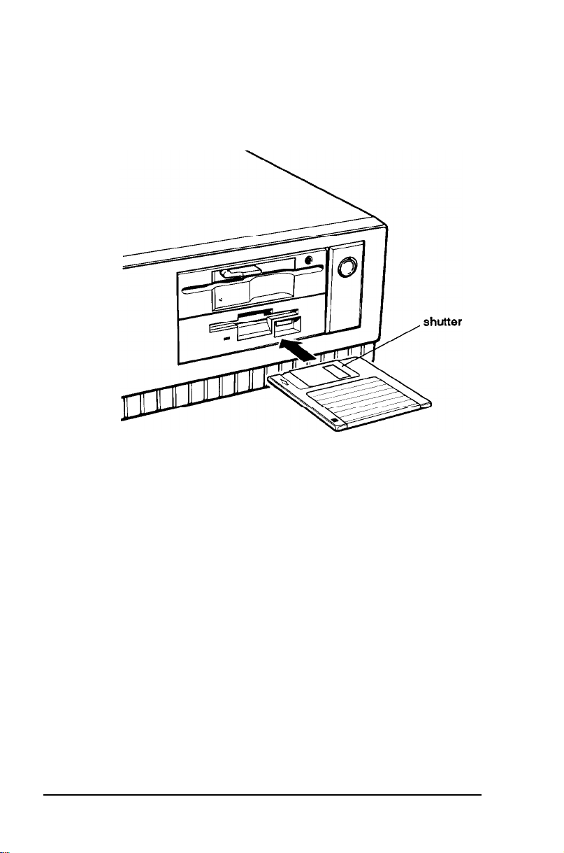
If you have a 3¼-inch diskette drive, insert the diskette with
the label facing up and the metal shutter leading into the drive,
as shown in the following illustration. Slide the diskette into the
drive until it clicks into place.
When you want to remove the diskette, make sure the drive
light is off; then press the release button. When the diskette
pops out, remove it and store it properly.
Caution
Never remove a diskette or reset or turn off the computer
while a diskette drive light is on. You could lose your data.
Also, be sure to remove all diskettes before you turn off the
computer.
3-20 Using Your Computer
Page 91

Formatting Diskettes
Before you can store data on a new diskette, you must format it
using the FORMAT command. Formatting prepares the diskette
so that MS-DOS can write data on it. You need to do this only
once, before you use the diskette for the first time.
You can also reformat previously used diskettes to store new
data. This process erases all the data on the diskette, so be sure
you do not want to save any of the files on a diskette before you
format it. See your MS-DOS Reference Manual for instructions
on using the FORMAT command.
Making Backup Copies
It is important to make copies of all your data and system
diskettes. Make backup (or working) copies of all diskettes that
contain programs, such as your MS-DOS diskettes and the
original Reference and Utility diskettes that came with your
computer. Then use only the copies. Store the original diskettes
in a safe place away from your working diskettes. Also, copy your
data diskettes regularly, whenever you revise them (to keep
them up-to-date) and store them away from your originals.
If you have a hard disk, you’ll probably use it to store the
programs and data files you use regularly. Keep backup copies of
all your files on diskettes.
You can copy your data in several ways:
❏
You can use the COPY or XCOPY command to copy
individual files or groups of files.
❏
You can use the DISKCOPY command to make an exact
duplicate of a diskette.
Using Your Computer
3-21
Page 92

❏
You can use the BACKUP command to back up hard disk
files to diskettes. Because BACKUP can split large files
across two or more diskettes, it makes more efficient use of
diskette space than COPY or XCOPY. It also allows you to
back up files that are larger than the capacity of your
diskettes.
See your MS-DOS Reference Manual for instructions on using
these commands.
Using a Hard Disk Drive
Using a hard disk is similar to using a diskette. However, the
hard disk provides several advantages:
❏
A 100MB hard disk can store as much data as approximately
eighty-two 1.2MB diskettes.
❏
Your computer can perform all disk-related operations faster.
❏
You can store frequently used programs and data files on the
hard disk, eliminating the inconvenience of swapping
diskettes to access different files.
The added storage capacity makes it easy to move back and forth
between different programs and data files. However, because it is
so easy to add programs and files to your hard disk, you may find
yourself trying to organize hundreds of files.
MS-DOS lets you keep related files together in directories and
subdirectories so they are easy to find and use. See your
MS-DOS Reference Manual for instructions on managing your
files and directories.
A hard disk must be partitioned and formatted before you can
use it. Be sure you have performed the procedures in your
MS-DOS Installation Guide to prepare your hard disk for use.
3-22
Using Your Computer
Page 93

Backing up the hard disk
While the hard disk is very reliable, it is essential to back up
your hard disk files to diskettes in case you lose some data
accidentally. Make copies of all your system and application
program diskettes before copying the programs to the hard disk.
After you create data files on the hard disk, be sure to copy them
to diskettes whenever you revise them to keep your backup
diskettes up-to-date.
Caring for your hard disk drive
Follow these precautions to protect your hard disk drive from
damage and to avoid losing data:
Never turn off or reset the computer when the hard disk
❏
access light is on. This light indicates that the computer is
copying data to or from the hard disk. If you interrupt this
process, you can lose data.
Never attempt to open the hard disk drive. The disk itself is
❏
enclosed in a sealed container to protect it from dust.
Before you move your computer even a short distance, you
❏
need to run the HDSIT program to prepare the hard disk for
moving, as described below.
Preparing the hard disk for moving
If you need to move your computer to a new location-whether
it is across the country or just across the room-you should run
the HDSIT program to protect the hard disk during the move.
The HDSIT program moves the disk drive’s read/write heads to
a region on the disk surface that does not contain data, and
locks them securely in position. This protects the hard disk from
being damaged if the computer is bumped accidentally.
Using Your Computer
3-23
Page 94

Follow these steps to run HDSIT:
Exit any program you are using and make sure the MS-DOS
1.
command prompt appears on the screen.
If you copied HDSIT to your hard disk (as described at the
2.
beginning of this chapter), type C :
onto the root directory of the hard disk.
If you do not have a hard disk or you did not copy HDSIT to
drive C, insert the Reference diskette in drive A. Then type
and press Enter to log onto that drive.
A
:
Type the following and press Enter:
3.
and press
Enter
to log
HDSIT
You see a message on the screen that tells you the disk drive’s
read/write heads will remain locked until you reset the computer
or turn the power off and on again. The computer locks the
heads and disables the keyboard. Remove any diskettes and turn
off the computer. You are now ready to move it to the new
location.
Note
If your computer
came with a 5¼-inch diskette drive and you
still have the original diskette drive protector card, you may
want to insert it into the drive prior to shipping your
computer to protect the read/write heads.
3-24
Using Your Computer
Page 95

Chapter 4
Enhancing System Operations
This chapter tells you how to use the following procedures to
enhance the operation of your computer:
❏
Using AUTOEXEC.BAT and other batch files
❏
Changing the processor speed
❏
Reassigning the diskette drives
❏
Using your computer as a network server
❏
Using expanded memory beyond 640KB
❏
Using special VGA features.
Using AUTOEXEC.BAT and Other Batch Files
As you get used to using MS-DOS and your application
programs, you may find that there are commands you need to
run frequently. You can automate the execution of these
commands by listing them in a special file called a “batch” file.
When you type the name of the batch file and press Enter,
MS-DOS executes the commands in the file just as if you had
typed each command from the keyboard.
If you have a word processing program that can save a file as a
text-only file (sometimes called an ASCII file), you can use that
program to create a batch file. You can also use the MS-DOS
COPY or EDLIN command to create the file. See your
MS-DOS Reference Manual for instructions on creating and
using batch files.
Enhancing System Operations 4-1
Page 96

One batch file that you may find particularly useful is called
AUTOEXEC.BAT. Every time you turn on your computer,
MS-DOS looks for the AUTOEXEC.BAT file and
automatically executes each of the commands.
When you install MS-DOS, it automatically creates an
AUTOEXECBAT file for you. To create or modify the file, you
can use the same programs that you use to create any other
batch file (COPY, EDLIN, or a word processing program that
can save a file as a text-only file). However, be sure to name the
file AUTOEXEC.BAT and store it in the root directory of the
hard disk or diskette from which you load MS-DOS.
See your MS-DOS Reference Manual for more information
about your AUTOEXEC.BAT file.
Changing the Processor Speed
Your computer’s processor can operate at two speeds: high and
low. High speed is 25 MHz and low speed simulates an 8 MHz
processor speed. On high, the computer can access memory
faster than on low. Your processor is set to operate at high speed
unless you change the speed to low or set the speed to change
automatically.
Note
When your computer is operating at high speed, the TURBO
light on the front panel is illuminated. The TURBO light is
off when your computer is operating at low speed.
You should use high speed for almost everything you do since
your programs will work faster. However, certain application
programs have specific timing requirements for diskette access
and can run only at the slower speed. See the manual for your
program to determine if this is the case.
4-2
Enhancing System Operations
Page 97

Some copy-protected programs require the computer to run at
low speed while accessing the program on a diskette. These
programs also usually require you to leave a key disk-the
diskette that contains the copy protection-in the diskette
drive. If you use a copy-protected program often, you may want
to set your processor speed to change automatically to low speed
when accessing the diskette and return to high speed when it is
finished.
There are different types of copy-protected programs. Depending
on the type you have, you may or may not want to set the
processor to automatic speed. Follow these guidelines:
❏
If you are using a copy-protected program that can run only
on a diskette or that requires a key disk, try to load the
program on high speed. If this works, you do not need to set
the speed to change automatically. If you can’t load the
program on high, set the speed to change automatically.
❏
If you are using a copy-protected program that does not
require a key disk but requires a special procedure to install
the program on a hard disk, set the speed to low while you
are installing the program. Once it is installed, set the speed
to high, where you should be able to leave it while you load
and run the program.
If this does not work, try installing and loading the program
at low speed and then change to high speed to run it. Do not
set the speed to change automatically.
There are three ways to change the processor speed:
❏
Run the Setup program on your Reference diskette
❏
Enter a keyboard command
❏ Run the ESPEED program.
Enhancing System Operations 4-3
Page 98

If you frequently use programs that require the processor to
operate at low speed or require the automatic speed change
when your computer is accessing a diskette, use Setup to change
the processor speed. See Chapter 2 for instructions.
If you use these programs only occasionally, you should use the
keyboard commands or the ESPEED program (described below)
to change the processor speed.
Entering Keyboard Commands
You can change the processor speed by entering one of the
following commands at the MS-DOS prompt:
Ctrl Alt +
Ctrl Alt Ctrl Alt *
For the +, -,
keypad. The commands do not work if you use the characters on
the main keyboard.
Changes the speed to high (25 MHz).
Changes the speed to low (simulated 8 MHz).
Tells the computer to change to low speed when
it is accessing a diskette.
and * characters, press the keys on the numeric
Note
You can use the commands listed above while you are
running a program.
However,
if you are running a program
that uses one of the same commands for another function,
you cannot use that command to change the processor speed.
For example, if you are running a program that uses the
Ctrl Alt - command to move the cursor, you cannot enter
Ctrl
Alt - to change the processor speed to low. When you
exit the program, you can enter these commands at the
MS-DOS prompt. Another alternative is to use the ESPEED
program, described below.
4-4
Enhancing System Operations
Page 99

To enter these commands, hold down the Ctrl key and the
Alt key and press the +, -,
The speed setting remains in effect until you press the RESET
button or turn off the computer, or until you change it again
using the Setup program, another keyboard command, or the
ESPEED program, described below.
or * key located cm the numeric keypad.
Using the ESPEED Program
The ESPEED program allows you to change the processor speed
to high or low, or set the speed to change automatically. This
method is convenient if your application program does not
recognize the Ctrl keyboard commands or if you want to include
the program command in a batch file.
The ESPEED program is provided with your system on the
Reference diskette. If you do not have a hard disk, insert your
Reference diskette in drive A and log onto drive A before you
enter the command to start the program.
If you have a hard disk drive, copy the file ESPEED.EXE from
your Reference diskette onto your hard disk-if you have not
already done so-and run the program from there. (See
Chapter 3 for more information.)
To run the ESPEED program, type the following at the
MS-DOS command prompt: and press Enter:
ESPEED
You see the following message:
Usage: ESPEED [/H][/L][/Al
/High
/Low
/Auto
set High speed (no auto)
set Low speed (no auto)
set Auto speed
Enhancing System Operations
4-5
Page 100

The message tells you the switches you should use to set the
speed to high, low, or automatic speed. At the MS-DOS prompt,
type the ESPEED command again and include the appropriate
switch, such as the following:
ESPEED /A
This command sets the processor speed to change to low speed
automatically when the computer accesses a diskette.
If you include the switch when you type the initial ESPEED
command, the program changes the speed without: displaying
the command options.
The processor speed you set remains in effect until you press the
RESET button or turn off the computer, or until you change it
using the Setup program, a keyboard command, or the ESPEED
program again.
Entering the ESPEED command in a batch file
You may want to run the ESPEED program by including the
command in a batch file. For example, if you have a program
called SAMPLE which requires an 8 MHz processor speed when
the program is running on a diskette, you could include the
following commands in a batch file to start the SAMPLE
program:
ESPEED /A
SAMPLE
You could name the batch file SAMP.BAT. Whenever you
need to run the SAMPLE program, insert the program diskette
into drive A. Then type SAMP and press Enter.
The computer changes the processor speed to automatic and
starts the SAMPLE program. When you access the program on
the diskette, the speed changes to low and then returns to high
when you are finished.
4-6
Enhancing System Operations
 Loading...