

Page 1
Epson EL 4S/33+
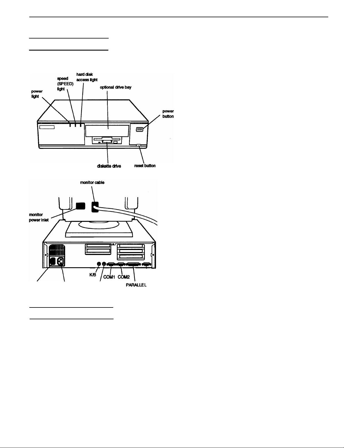
EL 4S/33+ Components
The following diagrams illustrate the outside of the
EL 4S/33+ system.
dskettec#fe
reeetbutton
Memory -
ROM
Video RAM
Shadow RAM
Memory
relocation
Internal cache
Math
coprocessor
Clock/calendar
2MB or 4MB RAM standard on SIMMs;
expandable to 16MB (maximum) using
256KB, 1MB, and 4MB SIMMs; SIMMs
must be 30-pin, 8-bit or 9-bit, fast-page
mode type with access speed of 70ns or
faster (preferably tin-plated)
64KB system BIOS and SETUP code
located in EPROM on main system board;
32KB video BIOS located in EPROM on
main system board
256KB DRAM on main system board;
expandable to 512KB or 1024KB using
70ns or 80ns 44256 DIP chips
32KB or 64KB, 0 or 1 wait state access
speed; system ROM BIOS and video ROM
can be copied into RAM
Supports relocation of 256KB of memory
from A0000h to BFFFFh and D0000h to
EFFFFh to extended memory
1KB built into microprocessor
Optional Cx83S87-33 coprocessor
available
Real-time clock, calendar, and CMOS
RAM socketed on main system board with
built-in battery backup
/
I I
CoMl cow
I
power inlet
AC outlet
KIB
MOUSE
Computer Specifications
CPU and Memory
32-bit CPU
System speed
Cyrix® or Texas Instruments® 486SLC,
33 MHz microprocessor with 16-bit data
bus
Fast and slow speeds available; fast speed
is 33 MHZ, slow speed is 8 MHz; speed
selection through SETUP program and
keyboard commands; zero wait state
memory access at fast speed; 0 or 1 wait
state memory access selectable through
SETUP
I
PAIGUEL
\
VGA
Controllers
Video
-
Diskette
Hard disk
Interfaces
Monitor
Parallel
Serial
Trident® VGA controller on main system
board; provides standard VGA resolutions
with 256KB memory and extended VGA
resolutions up to 1024 x 768 in 16 colors
with 512KB memory and 256 colors with
1MB memory
Controller on main system board supports
up to two diskette drives
Interface on main system board supports
up to two IDE hard disk drives with
built-in controllers; BIOS provides hard
disk auto-sensing function
VGA interface for analog monitor built
into system board; 15-pin, D-shell
connector
One standard 8-bit parallel, bidirectional
interface built into main system board;
25-pin, D-shell connector
Two RS-232C, programmable,
asynchronous interfaces built into main
system board; 9-pin, D-shell connectors
12/93 Epson EL 4S/33+ - 1
Page 2
Epson EL 4S/33+
Keyboard
Mouse
Game port
Option slots
Speaker
Mass storage
PS/2 compatible keyboard interface built
into main system board; 6-pin, mini DIN
connector; Num Lock setting selectable
through SETUP
PS/2 compatible mouse interface built
into main system board; 6-pin mini DIN
connector
10-pin game port interface on system
board; can control joy-stick functions with
the addition of an optional game port
connector
Three 16-bit, full-length and two 8-bit,
half-length I/O expansion slots, ISA
compatible, 8 MHz bus speed
Internal
Internal mounts:
Two
3l/frinch
with three or more option cards installed,
the power supply may only support one
internal drive
Externally accessible mounts:
One 3!4-inch wide, third-height drive and
one
S%nch
wide, one-inch high drives;
wide, half-height drive
Setup Program
Stored in ROM accessible by pressing
Ctrl Alt S at the MS-DOS prompt
Physical Characteristics
Width
Depth
Height
Weight
15.6 inches (396 mm)
14.5 inches (368 mm)
4.1 inches (104 mm)
15 lb (6.8 kg), without drives or keyboard
Power Supply
Type
Input ranges
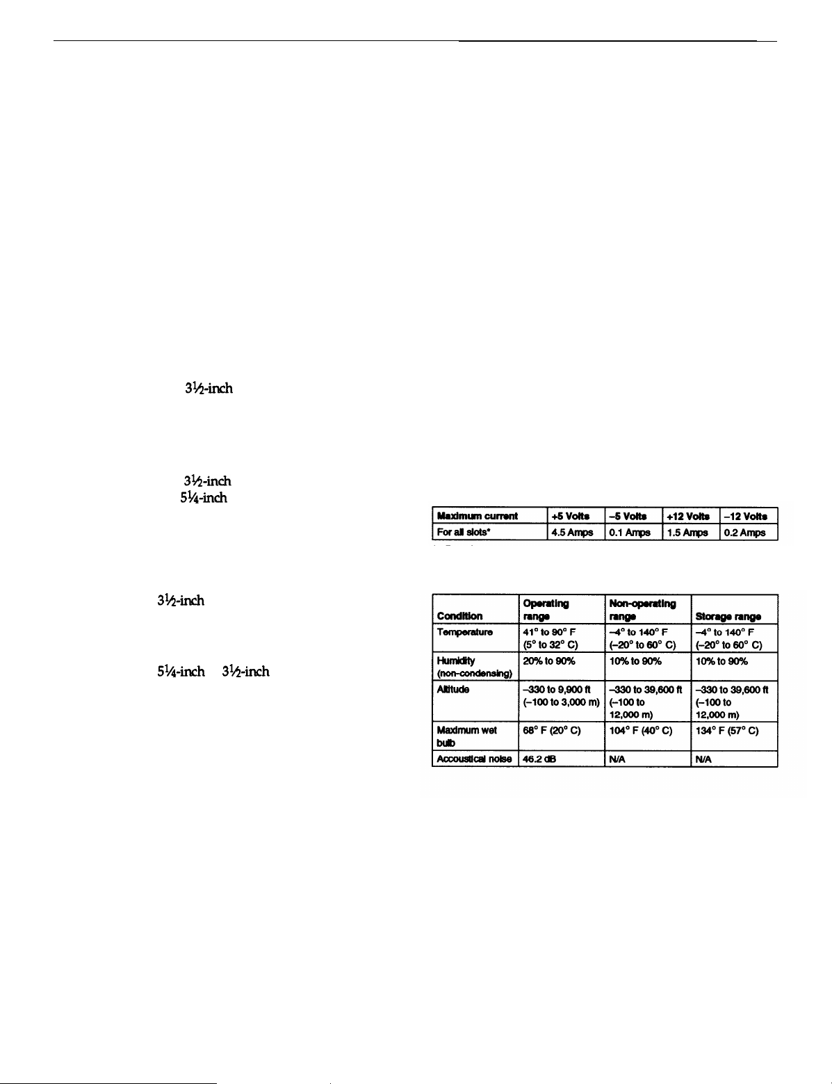
Maximum
outputs
Frequency
Cables
65 Watt, UL listed, fan-cooled
90 to 115,230 to 260 VAC
+5 VDC at 7.5 Amps, -5 VDC at
0.1 Amps, +12 VDC at 2.0 Amps,
-12 VDC at 0.3 Amps
50 to 60Hz
Two to main system board; four to mass
storage devices
Option Slot Power Limits
Diskette drives
Hard disk
drives
Other devices
Keyboard
3.5-inch diskette drive, 720KB or 1.44MB
storage capacity
5.25-inch
storage capacity
3l/cr-inch
to half-height size
Half-height tape drive, CD-ROM drive,
optical drive, or other storage device;
S!&inch or
Detachable, two-position height; 101 or
102 sculpted keys; countrydependent
main typewriter keyboard;
numeric/cursor control keypad; four-key
cursor control keypad; 12 function keys
diskette drive, 360KB
form factor hard disk drive(s), up
3&n&
with mounting frames
or 1.2MB
l
Based on a system containing one hard disk drive and one diskette drive.
Environmental Requirements
Epson EL 4S/33+ - 2
12/93
Page 3
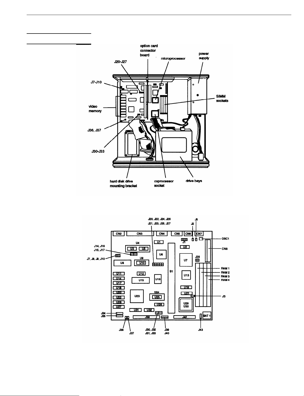
Major Subassemblies
Epson EL 4S/33+
System Board Components
12/93
Epson EL 4S/33+ - 3
Page 4

Epson EL 4S/33+
System board components and connectors
Jumper Settings
Use J10 with the built-in VGA adapter only. When J10 is ON, 1024 x 768
mode is interlaced and 800 x 600 mode
OFF, 1024 x 768 is non-interlaced and refresh at 60Hz; 800 x 600
refreshes at 72Hz. (VG 460 x 480 refreshes
setting)
“‘You can use MS-DOS to automatically reassign parallel and serial ports.
Check your MS-DOS manual for more information.
refreshes at 56Hz. When J1O is
at 60 Hz regardless of the J10
SIMM Installation
Your computer comes with 2MB or 4MB of memory on
SIMMs. You can increase the memory up to 16MB by
installing 256KB,
SIMM sockets. The following table shows the possible SIMM
configurations; do not install memory in any other
configuration.
SIMM
configuration
Use only 30-pin, fast-page mode SIMMs (preferably
tin-plated) that operate at an access speed of 70ns
(nanoseconds) or faster. Be sure all the SIMMs operate at the
same speed.
1MB, or 4MB SIMMs in the computer’s four
Epson EL 4S/33+ - 4
12/93
Page 5

Epson EL 4S/33+
Video Memory
The computer comes with 256KB of video memory. You can
increase the video memory to 512KB or 1024KB by installing
20-pin, 70ns or 80ns, 44256 DIP (Dual Inline Package) chips.
For the memory to work properly, you must install one chip
in each socket.
Video memory chip configuration
* Standard video memory
Resolutions and colors
Hard disk drive types
Math Coprocessor Upgrade
You can enhance your system’s performance for some
applications by installing a Cx83S87-33 math coprocessor.
Hard Disk Drive Types
The computer comes with a hard disk auto-sensing feature.
When you select
type in SETUP, the system detects the type of hard disk drive
you have installed when you boot and fills in the drive
information using values in the following table.
AUTO
DETECT 1
or 2 for your hard disk
Some older or preformated drives
auto-sensing feature. If the parame
match the parameter
your own drive type
of your hard
in SETUP.
do not support the
ters displayed do not
disk drive, you can define
12/93
Epson EL 4S/33+ - 5
Page 6

Epson EL 4S/33+
Drive Option Information
Standard diskette drive specifications
DMA Assignments
Level
DMA0
DMA1
DMA3
DMA6
DMA7
Assigned device
Reserved (8-bit)
Reserved (8-bit)
FDD controller (8-bit)
Reserved
Cascade for DMA controller 1
Reserved (16-bit)
Reserved (16-bit)
Reserved (16-bit)
(8-bit)
Hardware Interrupts
IRQ no.
lRQ0
IRQ1
IRQ2 Cascade from IRQ controller 2
IRQ3
IRQ4
IRQ5 Parallel port 2
IRQ6 FDD controller
Function
Timer output
Keyboard
Serial port 2
Serial port 1
Epson EL 4-S/33+ - 6
12/93
Page 7

Epson EL 4S/33+
System Memory Map
000FFFFFFh
System BIOS ROM: 64KB
Dupliated from 0F0000h
000FF0000h
Reserved for system board: 64KB
Duplicated from 0E0000h
000FE0000h
Extended memory
00100000h
System BlOS ROM: 64KB
Default Shadow RAM duplicated at FF0000h
000F0000h
Unused or l/O expansion ROM 160KB
Reserved for ROM on I/O adapters
000C8000h
000C0000h
VGA BlOS ROM: 32KB
Default shadow RAM
VGA text
(color): 32KB
Unused or VGA text
(monochrome): 32KB
System l/O Address Map
16MB (Maximum
system memory)
1MB
000A0000h
Video memory: 64KB
Reserved for graphics display buffer
640KB
12/93
Epson EL 4S/33+ - 7
Page 8

Epson EL 4S/33+
Connector Pin Assignments
Parallel port connector pin assignments (CN3)
*Active low logic
Serial port connector pin assignments (CN4 and CN5)
Hard disk drive connector pin assignments (J38)
*Active low logic
Speaker connector pin assignments (J34)
Optional game port connector pin assignments
VGA port connector pin assignments (CN2)
Power supply connector pin assignments (CN8)
Diskette drive connector pin assignments (J42)*
Optional game port interface pin assignments (J1)
Option card riser board connector pin assignments (S1)
*All odd=numbered pins are grounds
Epson EL4S/33+ - 8
12/93
Page 9

Epson EL 4S/33+
Option card riser hard connector pin assignments (S1) (continued)
*Active low logic
Use only 30-pin, 8-bit or 9-bit, fast-page mode SIMMs
(preferably tin-plated) that operate at an access speed of 70ns
(nanoseconds) or faster. SIMMs must operate at the same
speed.
Installation/Support Tips
Installing Diskette Drives
Make sure that the drive type has been correctly selected in
the SETUP program.
SIMM sockets (RAM1, RAM2, RAM3, RAM4)
*Active low logic
Installing Hard Disk Drives
When installing a hard disk drive, see the hard disk drive
type tables on pages 5 and 6 and use the auto-sensing
feature in SETUP to select the correct type number for the
drive. If the auto-sensing feature does not produce a
match for the drive, you can define your own drive type
by selecting User Def 1 or 2 as the type and entering
the drive’s exact parameters.
It is recommended that a 16-bit, AT-type hard disk
controller be used if you are installing a drive that cannot
use the embedded IDE interface. If you install a non-IDE
hard disk drive and controller card, you need to disable
the built-in IDE hard disk drive interface by moving
jumpers J21 and J30 to position 2-3.
If you plan to install two hard disk drives in the internal
bays, you must use flat-head screws (#6-32UNC x 8
FH,M,+) to secure the top drive to the mounting bracket.
If you are installing an ESDI hard disk drive, make sure
you disable the built-in IDE hard disk drive interface by
moving jumpers J21 and J30 to position 2-3. Also be sure
to remove the hard disk drive ribbon connector from the
system board.
12/93
Epson EL 4S/33+ - 9
Page 10

Epson EL 4S/33+
Software Problems
When installing a copy-protected software package, first
try the installation at high speed. If this does not work
properly, select low speed by pressing the Ctrl and Alt
keys and the - key on the numeric keypad
simultaneously. Try loading the program at low speed
and then switching to high speed, if possible.
When using a software package that uses a key disk as its
copy-protection method, try loading it at high speed. If
this does not work, load it at low speed.
Installing Option Cards
Although the EL 4S/33+ will support most full-length
option cards, option cards with an I/F connector on the
back may not fit into the option slot.
Make sum the power requirements of the option cards
you install do not exceed the power supply limitations.
If the computer locks up, the power supply may be
overloaded. On a system with three or more option cards,
the installation of a second hard disk drive may overload
the power supply.
If you are installing a video adapter card, make sure you
disable the built-in VGA by changing jumpers J7, J8, and
J9 to the Off position.
Information Reference List
Engineering Change Notices
None.
Technical Information Bulletins
None.
Product Support Bulletins
None.
Related Documentation
TM-EL3/4S33
EL4S33+ADD
PL-EL4S33+
400275000
Epson EL 3S/33 and 4S/33 Service Manual
Epson EL 4S/33+ Service Manual Addendum
Epson EL 4S/33+ Parts Price List
Epson EL 4S/33+ User’s Guide
COM Port Assignment
If you want to assign COM1 as COM3, you must set jumper
J24 to position 2-3. If you want to assign COM2 as COM4,
you must set jumper J26 to position 2-3.
System Problems
Q
Do not attempt to install OS/2, version 2.1, from
CD-ROM.
0
Do not use this computer as a server in a multi-LAN
environment.
0
When using SCO UNIX, the CMOS settings may be lost
when you boot the system. Also, keyboard input is not
accepted unless the Cyrix cache is disabled or the slow
refresh is set.
0
You cannot use an external hard disk drive with this
computer.
Q
When an extended memory test is run on QAFE, the
system hangs. This is a problem with the way QAFE
handles Cyrix memory.
Epson EL 4S/33+ - 10
12/93
 Loading...