

Page 1
EPSON
EPSON Stylus COLOR 3000
SERVICE MANUAL
COLOR INK JET PRINTER
SEIKO EPSON CORPORATION
4007664
Page 2

NOTICE
All rights reserved. Reproduction of any part of this manual in any form whatsoever
without SEIKO EPSON’s express written permission is forbidden.
The contents of this manual are subjects to change without notice.
All efforts have been made to ensure the accuracy of the contents of this manual.
However, should any errors be detected, SEIKO EPSON would greatly appreciate
being informed of them.
The above notwithstanding SEIKO EPSON can assume no responsibility f or any errors
in this manual or the consequences thereof.
EPSON is a registered trademark of SEIKO EPSON CORPORATION.
General Notice:
Other product names used herein are for identification purposes only and may be
trademarks or registered trademarks of their respective companies.
Copyright 1997 by SEIKO EPSON CORPORATION
Nagano, Japan
ii
Page 3

PRECAUTIONS
Precautionary notations throughout the text are categorized relative to 1) personal injury and 2)
damage to equipment.
WARNING
CAUTION
The precautionary measures itemized below should always be observed when performing
repair/maintenance procedures.
Signals a precaution which, if ignored, could res ult in ser ious or f atal per sonal injury.
Great caution should be exercised in performing procedures preceded by
WARNING Headings.
Signals a precaution which, if ignored, could result in damage to equipment.
WARNING
1. ALWAYS DISCONNECT THE PRODUCT FROM BOTH THE POWER SOURCE AND
PERIPHERAL DEVICES PERFORMING ANY MAINTENANCE OR REPAIR PROCEDURES.
2. NO WORK SHOULD BE PERFORMED ON THE UNIT BY PERSONS UNFAMILIAR WITH
BASIC SAFETY MEASURES AS DICTATED FOR ALL ELECTRONICS TECHNICIANS IN
THEIR LINE OF WORK.
3. WHEN PERFORMING TESTING AS DICTATED WITHIN THIS MANUAL. DO NOT
CONNECT THE UNIT TO A POWER SOURCE UNTIL INSTRUCTED TO DO SO. WHEN THE
POWER SUPPLY CABLE MUST BE CO NNECTED, USE EXT REME CAUT ION IN W O RKING
ON POWER SUPPLY AND OTHER ELECTRONIC COMPONENTS.
CAUTION
1. REPAIRS ON EPSON PRODUCT SHOULD BE PERFORMED O NLY BY EPSON CERTIFIED
REPAIR TECHNICIAN.
2. MAKE CERTAIN THAT T HE SOURCE VOLT AGE IS THE SAME AS T HE RATED VOLT AGE,
LISTED ON THE SERIAL NUMBER/RATING PLATE. IF THE EPSON PRODUCT HAS A
PRIMARY AC RATING DIFFERENT FROM AVAILABLE POWER SOURCE, DO NOT
CONNECT IT TO THE POWER SOURCE.
3. ALWAYS VERIFY THAT T HE EPSON PRODUCT HAS BEEN DISCONNECT ED FROM THE
POWER SOURCE BEFORE REMOVING OR REPLACING PRINTED CIRCUIT BOARDS
AND/OR INDIVIDUAL CHIPS.
4. IN ORDER TO PROTECT SENSITIVE MICROPROCESSORS AND CIRCUITRY, USE
STATIC DISCHARGE EQUIPMENT, SUCH AS ANTI-STATIC WRIST STRAPS, WHEN
ACCESSING INTERNAL COMPONENTS.
5. REPLACE MALFUNCTIONING COMPONENTS ONLY WITH THOSE COMPONENTS BY
THE MANUFACTURE; INTRODUCTION OF SECOND-SOURCE ICs OR OTHER
NONAPPROVED COMPONENTS MAY DAMAGE THE PRODUCT AND VOID ANY
APPLICABLE EPSON WARRANTY.
iii
Page 4

PREFACE
This manual descr ibes functions , theory of electrical and m echanical operations , maintenanc e, and
repair of Stylus COLOR 3000.
The instructions and procedur es included herein are intended for the experience r epair technician,
and attention should be given to the precautions on the preceding page. The Chapters are
organized as follows:
CHAPTER 1. GENERAL DESCRIPTION
Provides a general product overview, lists specifications, and illustrates the main components of the
printer.
CHAPTER 2. OPERATING PRINCIPLES
Describes the theory of printer operation.
CHAPTER 3. DISASSEMBLY AND ASSEMBLY
Includes a step-by-step guide for product disassembly and assembly.
CHAPTER 4. ADJUSTMENT
Includes a step-by-step guide for adjustment.
CHAPTER 5. TROUBLESHOOTING
Provides EPSON-approved techniques for troubleshooting.
CHAPTER 6. MAINTENANCE
Describes preventive maintenance techniques and lists lubricants and adhesives required to
service the equipment.
APPENDIX
Describes connector pin assignments, circuit diagrams, circuit board component layout and
exploded diagram.
The contents of this manual are subject to change without notice.
iv
Page 5

Page 6

TABLE OF CONTENTS
CHAPTER 1. GENERAL DESCRIPTION
CHAPTER 2. OPERATING PRINCIPLES
CHAPTER 3. DISASSEMBLY AND ASSEMBLY
CHAPTER 4. ADJUSTMENT
CHAPTER 5. TROUBLESHOOTING
CHAPTER 6. MAINTENANCE
APPENDIX
vi
Page 7

Chapter 1
Product Descriptions
1.1 Overview................................................................................................................1-1
1.2 Options and Consumables..................................................................................1-2
1.3 Specification.........................................................................................................1-4
1.3.1 Printing Specifications........................................................................................................... 1-4
1.3.2 Control codes ......................................................................................................................... 1-5
1.3.3 Character tables...................................................................................................................... 1-5
1.3.4 Paper Feeding......................................................................................................................... 1-6
1.3.5 Paper Handling ....................................................................................................................... 1-7
1.3.6 Printable Area ......................................................................................................................... 1-9
1.3.7 Adjust Lever.......................................................................................................................... 1-12
1.3.8 Ink Specification...................................................................................................................1-13
1.3.9 Input Data Buffer .................................................................................................................. 1-13
1.3.10 Electric Specifications ....................................................................................................... 1-14
1.3.11 Environmental Conditions.................................................................................................1-14
1.3.12 Reliability............................................................................................................................. 1-15
1.3.13 Safety Approvals ................................................................................................................ 1-15
1.3.14 CE Marking.......................................................................................................................... 1-15
1.3.15 Acoustic Noise.................................................................................................................... 1-15
1.3.16 Physical Specification........................................................................................................ 1-15
1.4 Interfaces.............................................................................................................1-16
1.4.1 Parallel Interface................................................................................................................... 1-16
1.4.2 Mac Serial Interface.............................................................................................................. 1-20
1.4.3 Optional Interface.................................................................................................................1-21
1.4.4 Prevention Hosts from Data Transfer Time-out.................................................................1-22
1.4.5 Interface Selection................................................................................................................ 1-22
1.4.6 Printer language ................................................................................................................... 1-22
1.5 Operation.............................................................................................................1-23
1.5.1 Control Panel ........................................................................................................................ 1-23
1.5.2 Default Setting ...................................................................................................................... 1-26
1.5.2.1 Setting Method ........................................................................................................ 1-26
1.5.2.2 Setting Menu ...........................................................................................................1-27
1.5.3 Printer Adjustment Mode..................................................................................................... 1-29
1.5.4 Printer Initialization .............................................................................................................. 1-30
1.5.5 Self-test Printing Mode ........................................................................................................ 1-30
1.5.6 Hexadecimal Dump Function..............................................................................................1-30
1.5.7 Monochrome Printing Mode................................................................................................ 1-30
1.5.8 Error Condition.....................................................................................................................1-31
1.6 Main Components...............................................................................................1-32
1.6.1 C203 MAIN Control Board.................................................................................................... 1-32
1.6.2 C172 PSB/PSE Board...........................................................................................................1-33
1.6.3 Control Panel ........................................................................................................................ 1-33
1.6.4 Printer Mechanism Unit ....................................................................................................... 1-33
1.6.5 Housing ................................................................................................................................. 1-33
Page 8
EPSON Stylus COLOR 3000
1.1 Overview
The EPSON Stylus COLOR 3000 is a high-performance color ink jet printer des igned f or the off ice market
as well as for plotter use with a wide paper availability up to full A2 size. The m ain features of this printer
are:
Paper availability in wide range
A-2 (ANSI C-size) paper supported
Printable area 410 mm (width) (A-2 /ANSI C-size paper)
Left and right margin 5 mm (A2-size paper)
0.5 inch (C-size paper)
Paper handling with ease
Built-in ASF with a wide paper page capability (up to C-size portrait) and high capacity
This ASF holds: 100 cut sheets (55g/m
10 envelops
30 transparency films
70 special paper *(up to A3)
30 special paper *(Super A3 or larger)
∗:360 dpi ink jet paper, photo quality ink jet paper.
Roll paper Fed with a high accuracy making no skew
Push tractor for the office use (for pre-printed continuous paper)
High Speed Printing
LQ mode 400 cps at 10 cpi
Draft mode 800 cps at 10 cpi
2 interfaces built-in and 1 optional interface card
Mac serial interface (up to approximately 900 kbps/1.8 Mbps)
Bi-directional parallel interface (IEEE1284 level 1 device)
Optional Type-B interface card
High print quality for color graphics
High Resolution 1440 (H) X 720 (V) dpi printing
4 color printing Cyan, Magenta, Yellow, Black
Printing Method Traditional and new micro weave printing
Smaller dot diameter for image improvement
4 scalable fonts and 5 LQ fonts
Scalable fonts Roman T, Sans Serif H, Roman, Sans Serif
LQ fonts Roman, Sans Serif, Courier, Prestige, Script (LQ)27
27 usable character tables
Italic, PC437, PC850, PC860, PC861, PC863, PC865, BRASCII,
Abicomp, Roman 8, ISO Latin 1, PC437 Greek, PC852, PC853,
PC855,PC857, PC866, PC869, MOZOAWIA, Code MJK, ISO 8559-7,
2
Rev. A
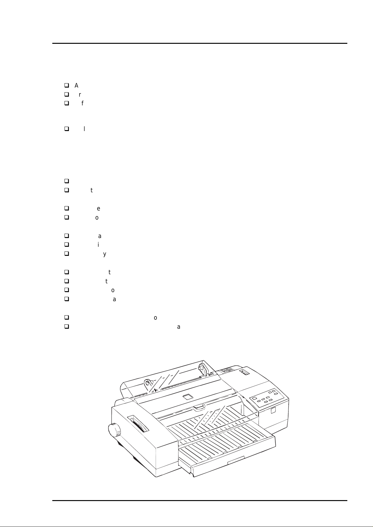
Figure 1-1. Exterior View of the EPSON Stylus COLOR 3000
1-1
Page 9
Product Descriptions
2
1.2 Options and Consumables
Table 1-1. Options and Consumables
Model Description
Serial Interface Cards
C82305∗/C82306∗
C82307∗/C82308∗
Parallel Interface Cards
C82310∗
C82345∗
C82313∗
C82314∗
C82315∗
C82312∗
C82331∗
C823311 Ethernet interface card (Multi-protocol)
C823401 Ether Talk interface card
C823431 Ethernet interface card (Netware)
Parallel Interface Cables
C83602∗
C83603∗/C83604∗
C83605∗/C83606∗
C81101∗
Ink Cartridges
S020118 Black ink cartridge
S020122 Yellow ink cartridge
S020126 Magenta ink cartridge
S020130 Cyan ink cartridge
EPSON Special Media
S041059 / S041025 EPSON 360 dpi ink jet paper (A4)
S041060 EPSON 360 dpi ink jet paper (Letter)
S041065/S041046 EPSON 360 dpi ink jet paper (A3)
S041066/S041647 EPSON 360 dpi ink jet paper (Super A3/B)
S041078 EPSON 360 dpi ink jet paper (A2)
S041061 / S041026 EPSON photo quality ink jet paper (A4)
S041062 EPSON photo quality ink jet paper (Letter)
S041067/S041048 EPSON photo quality ink jet paper (Legal)
S041068/S041045 EPSON photo quality ink jet paper (A3)
S041070/S041044 EPSON photo quality ink jet paper (B)
S041069/S041043 EPSON photo quality ink jet paper (Super A3/B)
S041079 EPSON photo quality ink jet paper (A2)
S041054 EPSON photo quality ink jet card (A6)
S041121 EPSON photo quality ink jet card (5 X 8 inch)
S041122 EPSON photo quality ink jet card (8 X10 inch)
Serial interface card
32 KB serial interface card
32 KB parallel interface card
32 KB Bi-directional parallel interface card
IEEE-488 interface card
Coax interface card
Twinax interface card
LoacalTalk™ interface card
Ethernet interface card
Parallel interface cable (shielded)
from D-SUB 25-pin (computer) to Amphenol 57 (printer)
Serial interface cable
from D-SUB 25-pin (computer) to D-SUB 25-pin (printer)
Serial interface cable
from D-SUB 9-pin (computer) to D-SUB 25-pin (printer)
Banner paper holder with cutting guide
(Banner Paper Kit)
1-
Rev. A
Page 10
EPSON Stylus COLOR 3000
3
Table 1-2. Options and Consumables (continued)
Model Description
S041071 EPSON photo quality glossy film (A4)
S041072 EPSON photo quality glossy film (Letter)
S041107 EPSON photo quality glossy film (A6)
S041073 EPSON photo quality glossy film (A3)
S041075 EPSON photo quality glossy film (B)
S041074 EPSON photo quality glossy film (Super A3/B)
S041126 EPSON photo quality glossy paper (A4)
S041124 EPSON photo quality glossy paper (Letter)
S041125 EPSON photo quality glossy paper (A3)
S041123 EPSON photo quality glossy paper (A2)
S041063 EPSON ink jet transparencies (A4)
S041064 EPSON ink jet transparencies (Letter)
S041106 EPSON photo quality self adhesive sheet (A4)
S041103 EPSON 360 dpi ink jet banner paper
S041102 EPSON photo quality banner paper
S041132 EPSON ink jet canvas
S041131 EPSON back light film (A3)
S041130 EPSON back light film (A2)
Note) The asterisk is a substitute for the last digit of the product number.
Rev. A
1-
Page 11
Product Descriptions
4
1.3 Specification
This section provides detailed information on the EPSON Stylus COLOR 3000.
1.3.1 Printing Specifications
Print method
Nozzle configuration
32/360 inch
On demand Ink jet
Monochrome 128 nozzles (32 x 4 staggered)
Color (magenta, cyan, yellow) 64 nozzles (32 x 4 staggered, each
color)
320/360 inch
144/360 inch
#127#128
32/360 inch
#125#126
32/360 inch
144/360 inch
#64
32/360 inch
#63
144/360 inch
#64
#63
32/360 inch
#64
#63
#2 #3#4#1
Black
Print direction
Print speed and printable columns
Bi-directional with logic-seeking
Table 1-3. Print Speed and Printable Columns for Character Mode
Character Pitch Printable Columns Draft Speed LQ Speed
10 cpi (Pica) 161 800 cps 400 cps
12 cpi (Elite) 193 960 cps 480 cps
15 cpi 242 1200 cps 600 cps
17.1 cpi (Pica condensed) 276 1368 cps 684 cps
20 cpi (Elite condensed) 322 1600 cps 800 cps
Table 1-4. Print Speed and Printable Area for Raster Graphic Mode
Print Mode Printable Area Available Dot CR Speed
180 dpi X 180 dpi 16.37 inch 2947 40 ips
360 dpi X 360 dpi 16.37 inch 5893 20 ips
720 dpi X 720 dpi 16.37 inch 11786 20 ips
1440 dpi X 720 dpi *
1
*1 Printing at 1440 X 720 dpi is available only using driver microweave.
*2 Can be printed by sending following command sequence.
1. Set print speed to 10 ips.
2. Print a 180 X 720 raster image.
3. Advance the paper using an increment of 31/720 inch.
4. Move the print position horizontally using an increment of 1/1440 inch.
5. Print a 180 X 720 raster image.
6. Advance the paper using an increment of 31/720 inch.
7. Repeat steps 2 to 6
.
#1
#2
Cyan
Paper feed direction
Figure 1-2. Nozzle Configuration
16.37 inch
11786*
#2
Magenta
2
#1
#2
Yellow
#1
10 ips
1-
Rev. A
Page 12
5
1.3.2 Control codes
ESCP/2 and expanded raster graphics code
EPSON Remote command
IBM XL24E emulation
1.3.3 Character tables
Legal and 14 international character sets
Standard version (27 character tables)
Italic table PC 437 (US, Standard Europe)
PC 850 (Multilingual) PC 860 (Portuguese)
PC 861 (IceLandic) PC 863 (Canadian-French)
PC 865 (Nordic) Abicomp
BRASCII Roman 8
ISO Latin 1 PC 437 (Greek)
PC 852 (East Europe) PC 853 (Turkish)
PC 855 (Cyrillic) PC 857 ( Turkish)
PC 866 (Russian) PC 869 (Greek)
MOZOAWIA (Poland) Code MJK (CSFR)
ISO 8559-7 (Latin, Greek) ISO Latin 1T (Turkish)
Bulgaria (Bulgaria) PC 774
Estonia ISO 8859-2 (ISO Latin 2)
PC 866 LAT
EPSON Stylus COLOR 3000
Typeface
Bit map LQ font
EPSON Roman 10 cpi, 12 cpi, 15 cpi, Proportional
EPSON Sans Serif 10 cpi, 12 cpi, 15 cpi, Proportional
EPSON Courier 10 cpi, 12 cpi, 15 cpi,
EPSON Prestige 10 cpi, 12 cpi, 15 cpi,
EPSON Script 10 cpi, 12 cpi, 15 cpi
Scalable font
EPSON Roman 10.5 pt.; 8 pt. − 32 pt. (2 pt. increments)
EPSON Sans Serif 10.5 pt.; 8 pt. − 32 pt. (2 pt. increments)
EPSON Roman T 10.5 pt.; 8 pt. − 32 pt. (2 pt. increments)
EPSON Sans Serif H 10.5 pt.; 8 pt. − 32 pt. (2 pt. increments)
Note) Each typeface has 4 variations:
Normal, Bold, Italic, and Bold Italic
An example of variations for Epson Roman is as follows:
Epson Roman normal
Epsom Roman bold
Epson Roman italic
Epson Roman bold italic
Rev. A
1-
Page 13
Product Descriptions
6
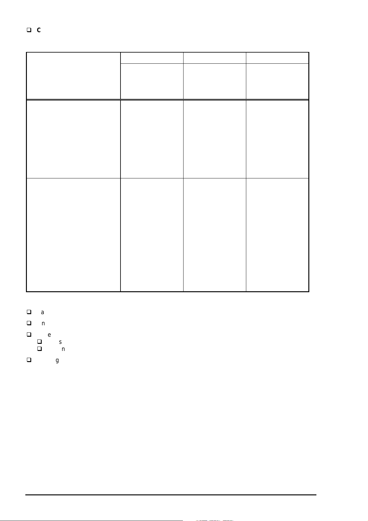
Combination of character tables and typefaces
Table 1-5. Character Tables and Fonts
Bitmap Fonts Scalable Fonts Scalable Fonts
Character Tables
(Standard version)
Italic table
PC 437 (US Standard Europe)
PC 850 (Multilingual)
PC 860 (Portuguese))
PC 861 (Icelandic)
PC 863 (Canadian-French)
PC 865 (Nordic)
BRASCII
Abicomp
Roman 8
ISO Latin 1
PC 437 (Greek)
PC 852 (East Europe)
PC 853 (Turkish)
PC 855 (Cyrillic)
PC 857 (Turkish)
PC 866 (Russian)
PC 869 (Greek)
MAZOWIA (Poland)
Code MJK (CSFR)
ISO 8859-7 (Latin/Greek)
ISO Latin 1T (Turkish)
Bulgaria (Bulgaria)
PC 774
Estonia
ISO 8859-2 (ISO Latin 2)
PC 866 LAT
EPSON Roman
EPSON Sans Serif
EPSON Courier
EPSON Prestige
EPSON Script
Supported Supported Supported
Supported Supported
EPSON Roman
EPSON Sans Serif
EPSON Roman T
EPSON Sans Serif H
Not
Supported
1.3.4 Paper Feeding
Paper transport method Friction feed with built-in auto sheet feeder (ASF)
Line spacing 1/6, 1/8 inch or programmable at 1/360 inch
Paper path
Cut-sheet ASF (Front entry)
Continuous paper Rear tractor
Feeding speed 100 ms per line (1 line = 1/3 inch)
4.0 inches per second
1-
Rev. A
Page 14
EPSON Stylus COLOR 3000
7
)
)
)
1.3.5 Paper Handling
Cut Sheet
Table 1-6. Cut Sheet Specification
Width Length
Statement 139.7 mm (5.5”) 215.9 mm (8.5”)
A5 148 mm (5.8”) 210 mm (8.3”)
B5 182 mm (7.2”) 257 mm (10.1”)
Executive 184.2 mm (7.3”) 266.7 mm (10.5”)
A4 210 mm (8.3”) 297 mm (11.7”)
Paper Letter 215.9 mm (8.5”) 279.4 mm (11.0”)
Legal 215.4 mm (8.5”) 355.6 mm (14.0”)
B4 257 mm (10.1”) 364 mm (14.3”)
ANSI B 279.4 mm (11”) 431.8 mm (17”)
A3 297 mm (11.7”) 420 mm (16.5”)
A3 wide 329 mm (13.0”) 483 mm (19.0”)
A2 420 mm (16.5”) 594 mm (23.4”)
ANSI C 431.8 mm (17.0”) 558.8 mm (22.0”)
Paper Thickness 0.08 mm (0.0031”) to 0.15 mm (0.0059”
Paper Weight ASF 64 g/ m2 (17 lb.) to 90 g/ m2 (24 lb.)
Manual insertion 52 g/ m2 (14 lb.) to 90 g/ m2 (24 lb.)
Quality Exclusive paper, Bond paper, PPC
Note)
1. Be sure to use the designated face of exclusive paper.
2. Make sure that the paper has no crease, curl, harshness or rip.
3. When placing paper in ASF, be sure not to overload it so that the paper will not dislocate. At manual
insertion, place the paper using the mark on the case for basis and insert it until it meets resistance.
Transparency
Table 1-7. Transparency Specification
Width Length
Size
Paper Thickness 0.075 mm (0.003”) to 0.085 mm (0.0033”
A4 210 mm (8.3”) 297 mm (11.7”)
Letter 215.9 mm (8.5”) 279.4 mm (11.0”)
Note)
1. Transparency printing is only available at normal temperatures.
2. Transparency paper must be printed on the designated side.
Envelope
Table 1-8. Envelope Specification
Width Length
Size No.10 241.3 mm (9 1/2”) 104.8 mm (4 1/8”)
DL 220 mm (8.7”) 110 mm (4.3)
C5 229 mm (9”) 162 mm (6.4”)
Paper Thickness 0.16 mm (0.006”) to 0.52 mm (0.02”
Paper Weight 45 g/m2 (12 lb.) to 90 g/ m2 (24 lb.)
Quality Bond paper, Plain paper, Airmail
Note)
1. Envelope printing is only available at normal temperatures.
2. Place the longer side of the envelope horizontally when setting.
Rev. A
1-
Page 15
Product Descriptions
8
)
)
)
)
Index Card
Table 1-9. Index Card Specification
Size A6 index card 105 mm (4.1”) (width) 148 mm (5.82”) (length)
Paper Thickness 0.23 mm (0.0091”) or less
Note) Make sure that the paper has no crease, curl, harshness or rip.
Note) Label must be printed at normal room temperature.
Labels (Cut Sheet)
Table 1-10. Label Specification
Width Length
Size A4 210 mm (8.3”) 297 mm (11.7”)
Letter 216 mm (8.5”) 279 mm (11.0”)
Paper Thickness 0.2 mm (0.0079”) or less (including base sheet
Quality Label for page printer
Note) Label must be printed at normal room temperature.
Note) Make sure that the sheet has no crease, curl, harshness or rip.
Continuous Paper
Table 1-11. Continuous Paper Specification
Size Width 101.6 mm (4”) to 406.4 mm (16”)
Folding length 101.6 mm (4”)
Paper Thickness 0.065 mm (0.0026”) to 0.11 mm (0.0043”
Paper Weight 52 g/ m2 (14 lb.) to 82 g/ m2 (22 lb.)
Note) Make sure that the sheet has no crease, curl, harshness or rip.
Labels (Continuous)
Table 1-12. Label (Continuous) Specification
Base sheet Width 101.6 mm (4”) to 406.4 mm (16”)
Size Folding length 101.6 mm (4”)
Label Width 63.5 mm (2.5”)
Length 23.9 mm (0.94”)
Paper Thickness 0.02 mm (0.0079”) or less (including base sheet
0.12 mm (0.0047”) or less (label only)
Quality Plain paper
Note) Label (continuous) must be printed at normal room temperatures.
Note) Make sure that the sheet has no crease, curl, harshness or rip.
Banner
Table 1-13. Banner Specification
Size Width Length
210 mm (8.3) to 432 mm (17.0”) 5.0 m or less (196.9”)
Paper Thickness 0.08 mm (0.0031”) to 0.1 mm (0.0039”
Paper Weight 64 g/m2 (17 lb.) to 82 g/ m2 (22 lb.)
Quality Plain paper
1-
Rev. A
Page 16
9
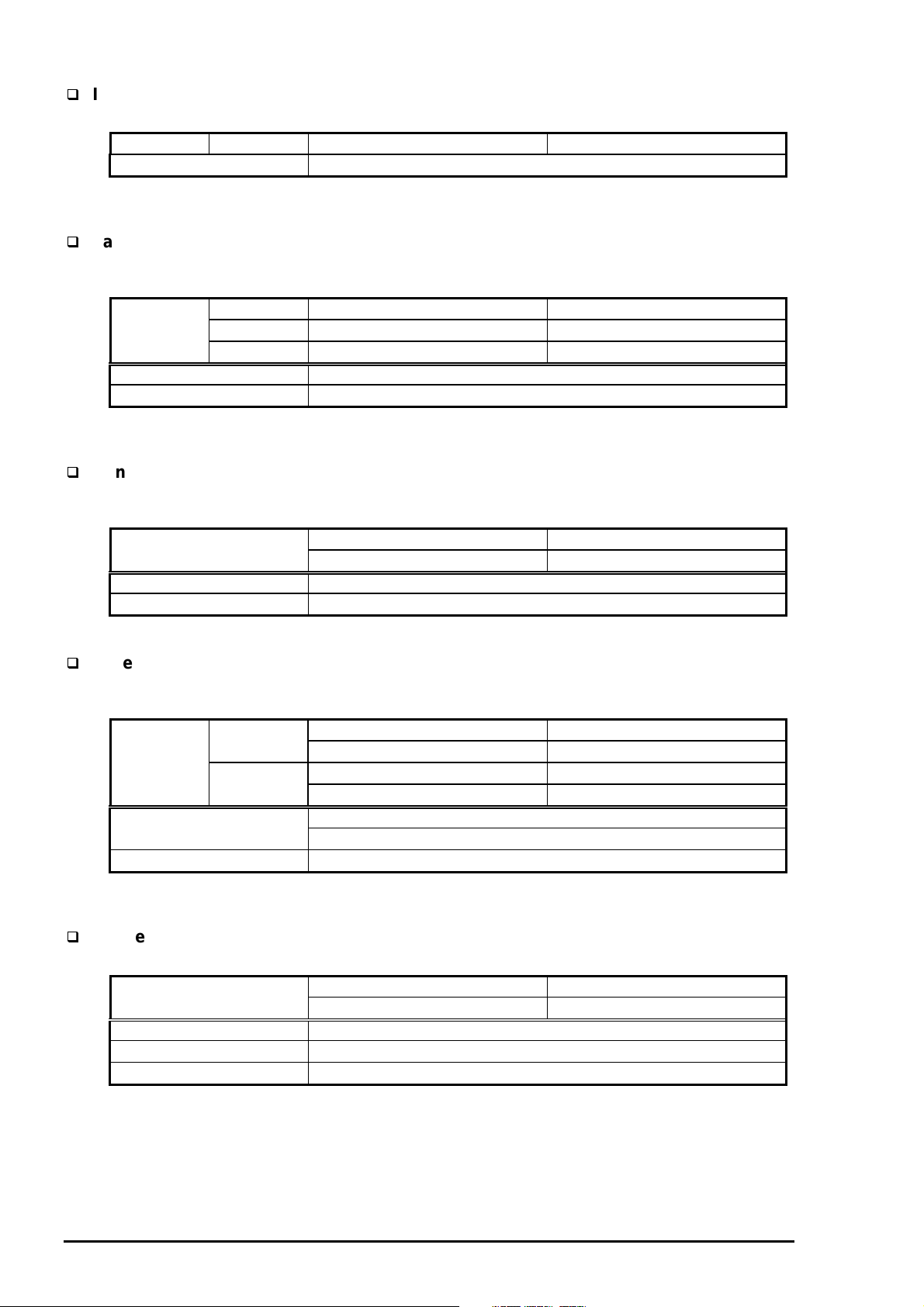
1.3.6 Printable Area
Cut Sheet / Label (cut sheet)
EPSON Stylus COLOR 3000
PW
LM RM
TM
Printable Area
PL
BM
Figure 1-3. Printable Area for Cut Sheet
Table 1-14. Minimum Margins for Different Cut Sheet Sizes
Paper width Left margin Right margin Top margin Bottom margin
Up to 420 mm
(16.5”)
420 mm (16.5”)
A3 landscape
3 mm
(0.12 inch)
5 mm
(0.20 inch)
3 mm
(0.12 inch)
5 mm
(0.2 inch)
3 mm
(0.12 inch)
3 mm
(0.12 inch)
14 mm
(0.54 inch)
14 mm
(0.54 inch)
A2
432 mm(17.02)
ANSI B landscape
5 mm
(0.20 inch)
11 mm
(0.43 inch)
3 mm
(0.12 inch)
14 mm
(0.54 inch)
ANSI C
Rev. A
1-
Page 17
Product Descriptions
0
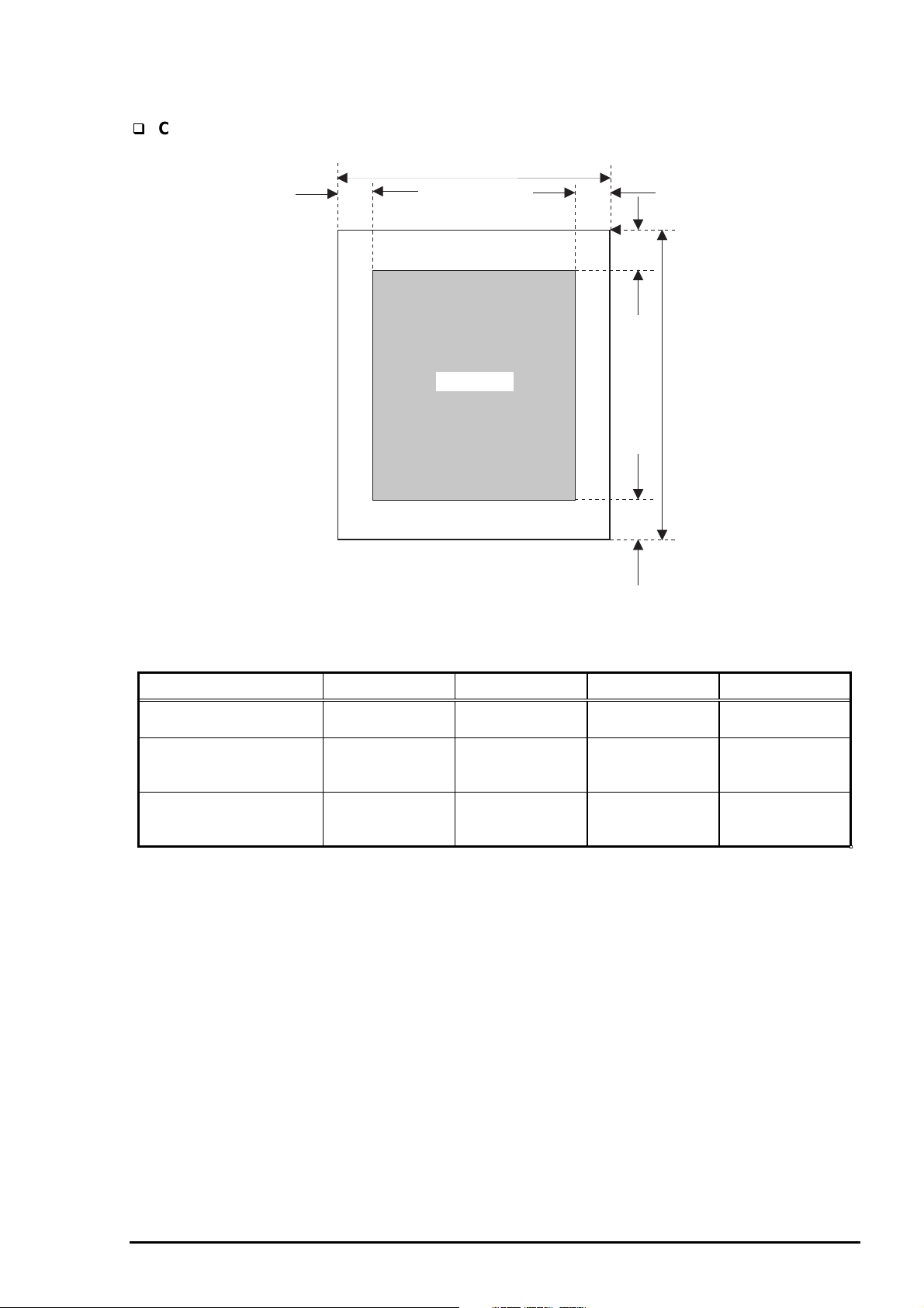
Envelope
Left Margin
(minimum)
3 mm
(0.12”)
LM
Printable area
Figure 1-4. Printable Area for Envelopes
Table 1-15. Minimum Margin for Envelope
Right Margin
(minimum)
Top Margin
(minimum)
3 mm
(0.12”)
3 mm
(0.12”)
RM
TM
BM
Bottom Margin
(minimum)
14 mm
(0.55”)
1-1
Rev. A
Page 18
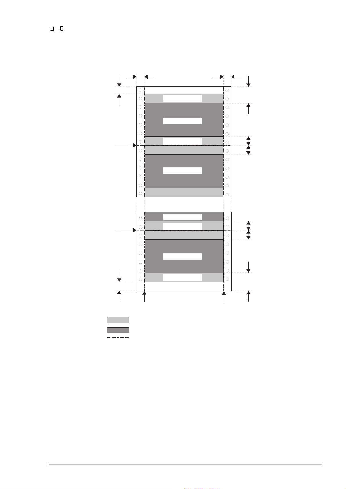
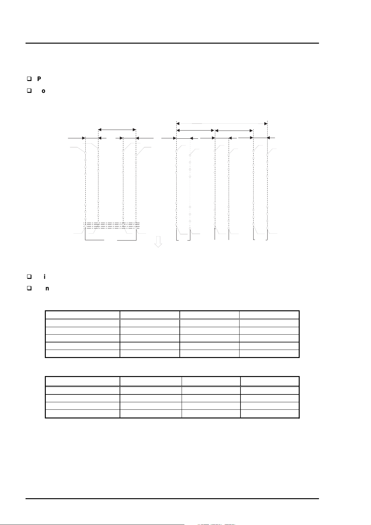
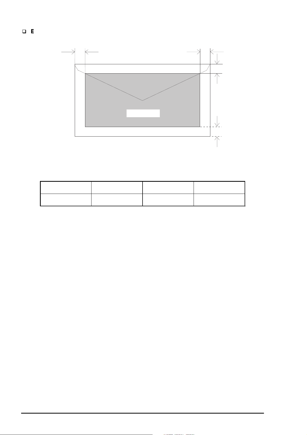
Continuous Paper / Label (Continuous Paper)
EPSON Stylus COLOR 3000
More than
3 mm (0.12 ")
Perforation
Perforation
More than
13 mm (0.51") *1
Printable are 1
Printable area 2
Printable are 1
Printable area 2
Printable area 2
Printable are 1
More than
13 mm (0.51") *1
More than
12.5 mm (0.49")
More than
9 mm (0.35")
More than
9 mm (0.35")
More than
9 mm (0.35")
More than
9 mm (0.35")
Printable area 2
Printable are 1
More than
14 mm (0.55")
Perforation
Printable Area 1: Paper feed pitch is not guaranteed in this area.
Printable Area 2: Paper feed pitch is guaranteed in this area.
Perforation
*1 : When the paper width is more than 406.4 mm (16"), this width is more than
38 mm (1.50").
Figure 1-5. Printable Area for Continuous Paper
Note) Base sheet of label (continuous) is not printing area.
Perforation
More than
134 mm (5.28")
Rev. A
1-1 1
Page 19
Product Descriptions
2
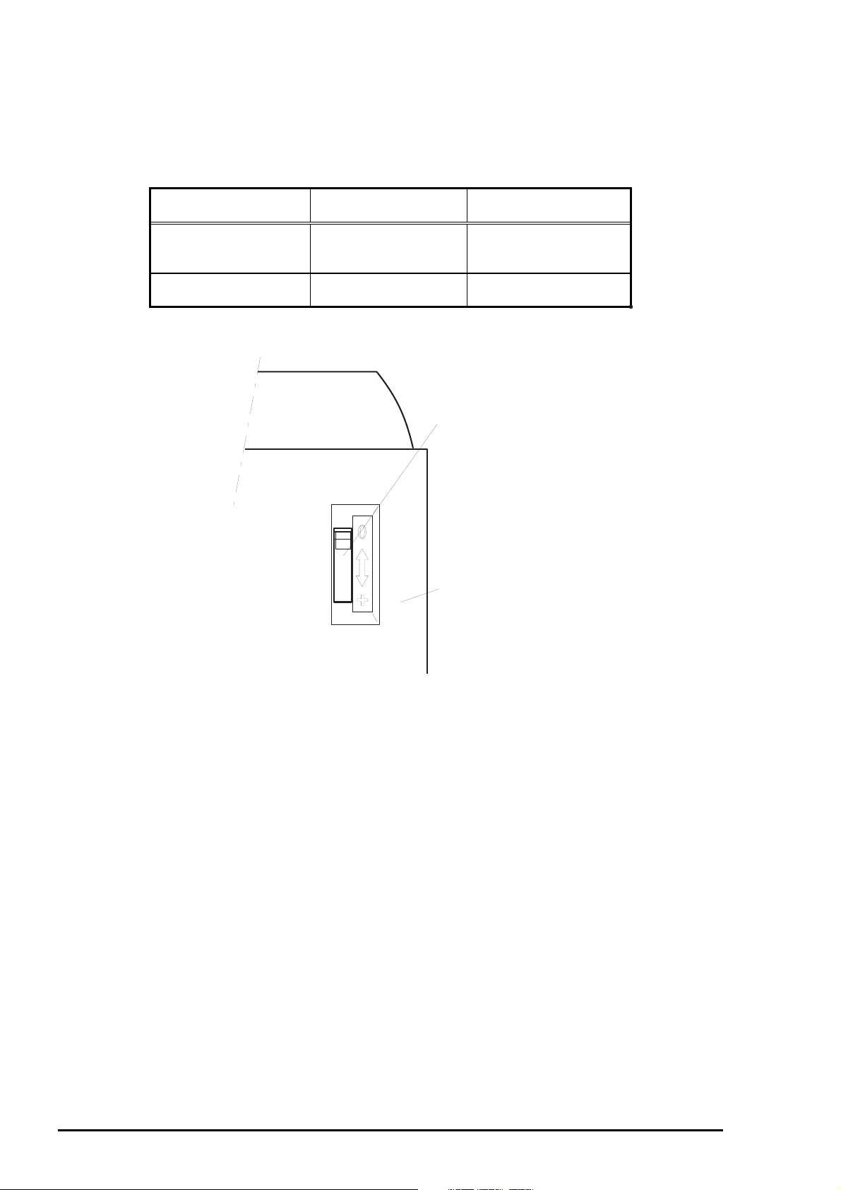
1.3.7 Adjust Lever
The adjust lever, located at the right and upper side in the printer cover, is used to adj ust the gap between
the paper and platen. The adjust lever must be set to the proper pos ition according to the paper type to
avoid ink smudging caused by ink’s contact with paper.
Table 1-16. Adjust Lever Position
Paper Type Lever Position
Cut sheet
Transparency
Continuous paper
Envelopes
Index card
Far side (0) 0 mm
Near side (1) + 0.7 mm
Platen Gap Adjustment
Value
PG Adjust Lever
Printer Cover
Figure 1-6. Adjust Lever Settings
1-1
Rev. A
Page 20
EPSON Stylus COLOR 3000
3
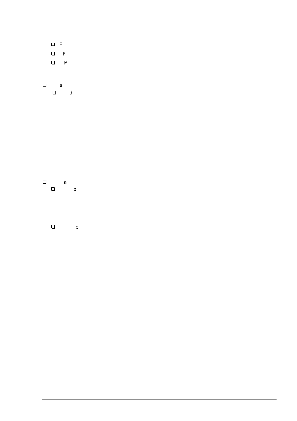
1.3.8 Ink Specification
Black ink cartridge
Table 1-17. Black Ink Cartridge Specifications
Black Ink Cartridge
Type Exclusive ink cartridge
Color Black
Print capacity 3800 pages / A4 (ISO/IEC10561 Letter Pattern at 360 dpi)
Ink life 2 years from indicated production date
Storage Temperature
At storage -20 °C to 40 °C (-4 to 104°F)
At packing storage -30 °C to 40 °C (-22 to 104°F)
At transit (Packed) -30 °C to 60 °C (-22 to 140°F)
Dimension 25.1 mm (W) X 139.6 mm (D) X 105.3 mm (H)
(1.22” X5.49” X4.14”)
*1 The cartridge must not be kept at 40 °C (104 °F) for more than a month.
*2 The cartridge must not be kept at 60 °C (140°F) for more than 120 hours.
Note)
1. The cartridge must not be refilled. The ink cartridge is a consumable item.
2. Do not use the cartridge whose ink life has expired.
3. When the ink freezes below -4°C (23°F); it will be usable again after keeping it for more than 3 hours at
room temperature.
* 1
*1
*1*2
Color ink cartridge
Table 1-18. Color Ink Cartridge Specifications
Color Ink Cartridge
Type Exclusive ink cartridge
Color Magenta, Cyan, Yellow
Print capacity 2100 pages A4 (at 360 dpi, 5 % duty each color)
Ink life 2 years from indicated production date
Storage Temperature
At storage -20 °C to 40 °C (-4 to 104°F)
At packing storage -30 °C to 40 °C (-22 to 104°F)
At transit (Packed) -30 °C to 60 °C (-22 to 104°F)
* 1
*1
*1*2
Dimension 25.1 mm (W) X 139.6 mm (D) X 105.3 mm (H)
(0.98”X5.49” X 4.14”)
*1 The cartridge must not be kept at 40 °C (104 °F) for more than a month.
*2 The cartridge must not be kept at 60 °C (140°F) for more than 120 hours.
Note)
1. The cartridge must not be refilled. The ink cartridge is a consumable item.
2. Do not use the cartridge whose ink life has expired.
3. When the ink freezes below -4°C (23°F); it will be usable again after keeping it for more than 3 hours at
room temperature.
1.3.9 Input Data Buffer
Input data buffer :64 Kbytes
Rev. A
1-1
Page 21
Product Descriptions
4
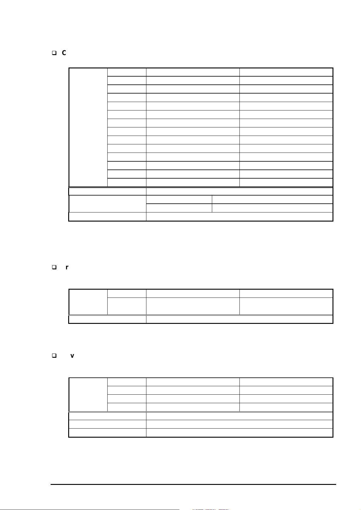
1.3.10 Electric Specifications
120 V version
Rated voltage AC 120 V
Input voltage range AC 103.5 to 132 V
Rated frequency renege 50 to 60 Hz
Input frequency range 49.5 to 60.5 Hz
Rated current 0.7 A (maximum)
Power consumption Approximately 21 W (ISO/IEC 10561 Letter pattern)
Energy Star program compliant
Insulation resistance 10 M ohms min. (Between AC line and chassis, 500 VDC)
Dielectric strength AC 1,000 V rms. For 1 minute or
AC 1,200 V rms. For 1 second (Between AC line and chassis)
220 - 240V version
Rated voltage AC 220 to 240 V
Input voltage range AC 198 to 264 V
Rated frequency renege 50 to 60 Hz
Input frequency range 49.5 to 60.5 Hz
Rated current 0.4 A (maximum)
Power consumption Approximately 21 W (ISO/IEC 10561 Letter pattern)
Energy Star program compliant
Insulation resistance 10 M ohms min. (Between AC line and chassis, DC 500 V)
Dielectric strength AC 1,500 Vrms. For 1 minute (Between AC line and chassis)
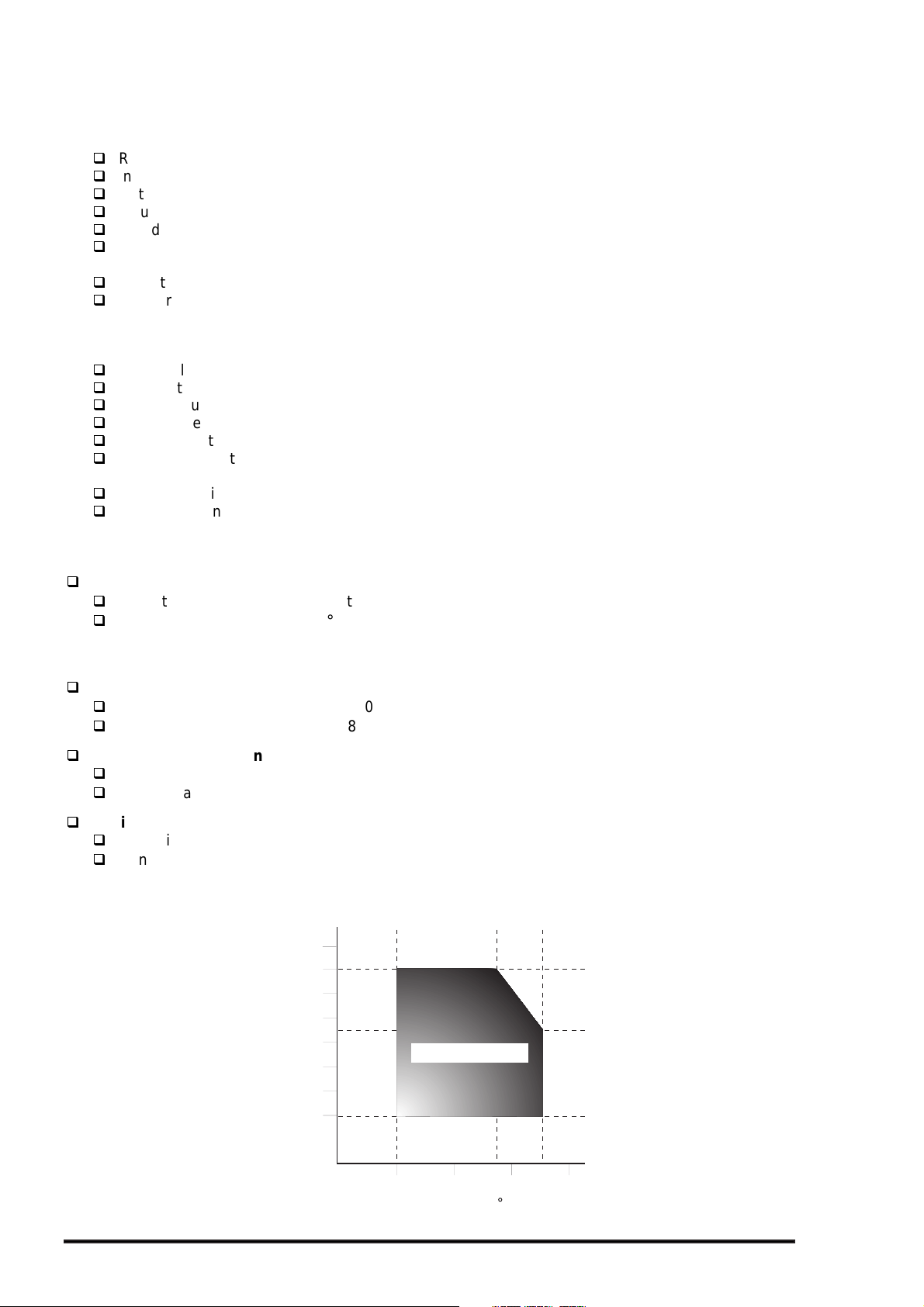
1.3.11 Environmental Conditions
Temperature
Operating*
Non operating*
Humidity
Operating*
Non operating*
Resistance to vibration
Operating 0.15 G
Non-operating*
Resistance to shock
Operating 1 G within 1 ms
Non-operating*
*1 :Refer to the table below for guaranteed range.
*2 :In shipment container.
1
2
10°C to 35°C
-20°C to 60°C
1 month at 40 °C (104 °F)
120 hours at 60 °C (140 °F)
1
20% to 80% RH (without condensation)
2
2
2
Humidity (%)
5% to 85% RH (without condensation)
0.50 G
2 G within 2 ms
90
80
70
60
50
40
30
20
Operating Environment
.
35
10
20
Temperature ( C)
27
30
40
Figure 1-7. Environmental Conditions
1-1
Rev. A
Page 22

5
1.3.12 Reliability
Total print volume 75,000 pages (A3)
Print head life 2,000 million dots /nozzle
1.3.13 Safety Approvals
120 V version
Safety standards UL1950 with D3
CSA22.2 No. 950 with D3
EMI FCC part15 subpart B class B
CSA C108.8 class B
220 - 240 V version
Safety standards EN 60950 (VDE, NEMKO)
EMI EN 55022 (CISPR Pub.22) class B
AS/NZS 3548 class B
1.3.14 CE Marking
220 - 240 V version
Low Voltage Directive 73/23/EEC EN60950
EMC Directive 89/336/EEC EN55022 class B
EN61000-3-2
EN61000-3-3
EN50082-1
IEC801-2
IEC801-3
IEC801-4
EPSON Stylus COLOR 3000
1.3.15 Acoustic Noise
Noise level Approximately 45 dB (A) (According to ISO 7779)
1.3.16 Physical Specification
Weight 22.5 Kg
Dimension 810 mm (W) X 565 mm (D) X 240 mm (H)
(31.9” X 22.2” X 9.4”)
Refer to Appendix for details.
Rev. A
1-1
Page 23
Product Descriptions
6
1.4 Interfaces
The EPSON Stylus COLOR 3000 is equipped with the parallel and Mac serial interfaces and a card slot
for an optional Type-B interface. This section provides information on each interface.
1.4.1 Parallel Interface
Forward Channel
Transmission mode
Synchronization
Handshaking
Signal level
Adaptable connector
Table 1-19. Signal level of TTL Compatible (IEEE-1284 level 1 device)
Parameter Minimum Maximum Condition
VOH* - 5.5 V
VOL* -0.5 V IOH* - 0.32 mA VOH = 2.4 V
IOL* - 12 mA VOL = 0.4 V
CO - 50 pf
VIH - 2.0 V
VIL 0.8 V IIH - 0.32 mA VIH = 2.0 V
IIL - 12 mA VIL = 0.8 V
CI - 50 pf
∗ A LOW logic level on the Logic H signal is as follows:
2.0 V or less when the printer is powered off.
3.0 V or more when the printer is powered on.
The receiver provides an impedance equivalent to 7.5 K ohms to ground.
8 bit parallel, IEEE-1284 compatibility mode
By /STROBE pulse
By /BUSY and /ACKNLG signal
TTL compatible
57-30360 (Amphenol) or equivalent
The BUSY signal is set HIGH before setting either /ERROR LOW or PE HIGH and held HIGH until all
these signals return to an inactive state. The BUSY signal is HIGH in the following cases:
During data entry.
When the input data buffer is full.
While /INIT signal is at low level or during hardware initialization.
During a printer error condition (See /ERROR signal).
During test printing.
When the printer is in default setting mode.
When the parallel interface is not selected.
The /ERROR signal is LOW when one of the following errors has occurred:
Printer hardware error (fatal error)
Paper-out error
Paper-jam error
Ink-out error
The PE signal is high level during paper-out error.
1-1
Rev. A
Page 24
EPSON Stylus COLOR 3000
7
DATA
STORBE
0.5 us (min.)
BUSY
ACKNLG
DATA (n)
0.5 us (min.)
0.5 us (min.)
0 (min.)
DATA (n+1)
0 (min.)
0 (min.)
5 us (type.)
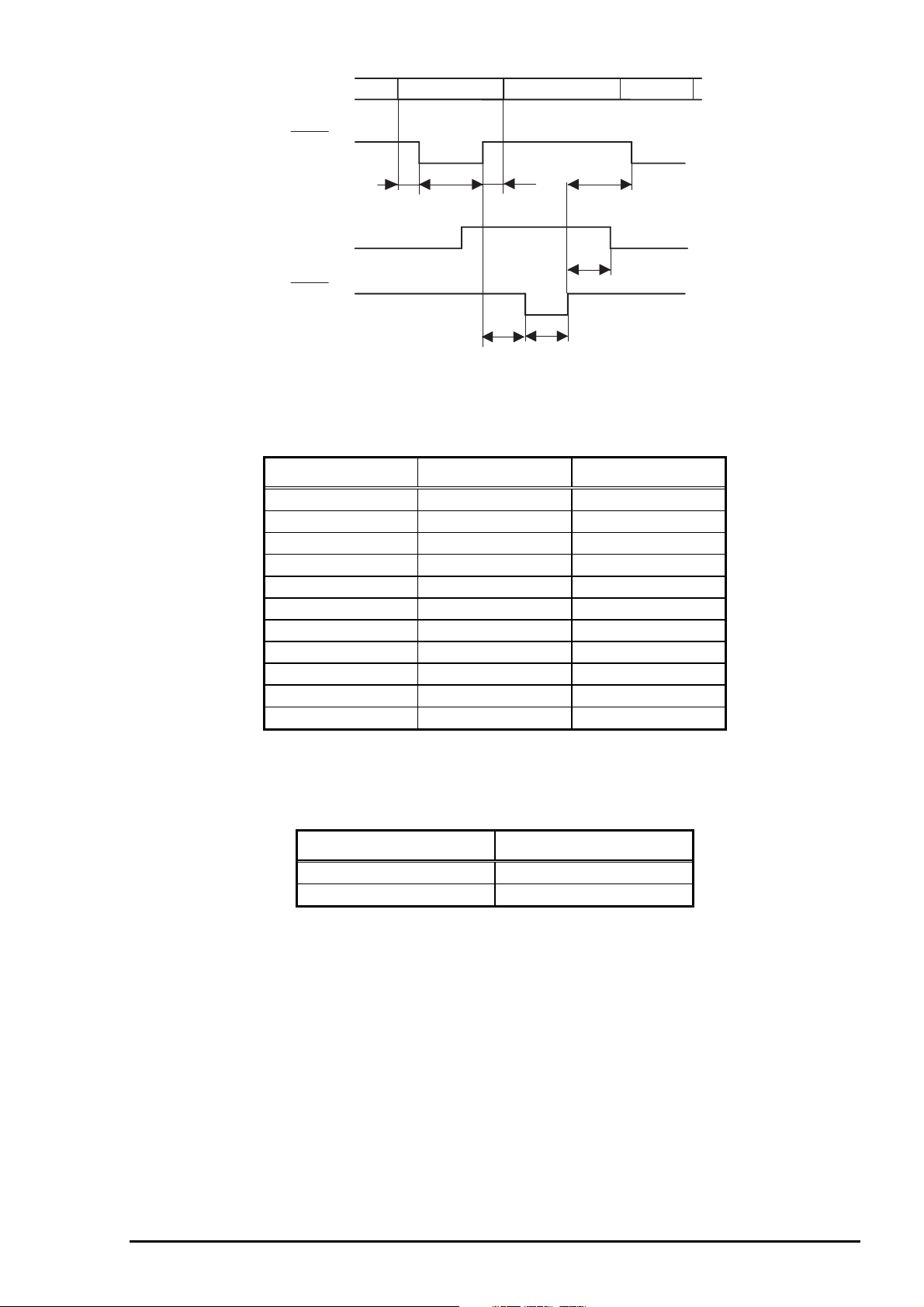
Figure 1-8. Data Transmission Timing
Table 1-20. Data Transmission Timing
Parameter Minimum Maximum
tsetup 500 ns thold 500 ns tstb 500 ns tready 0 tbusy - 500 ns
tt-out - 120 ns
tt-in - 200 ns
treply - tack*** 500 ns 10 us
tnbusy 0 tnext 0 -
Note) tt-out shows the rise and fall time of every output signal.
tt-in shows the rise and fall time of every input signal.
Typical time of tack is shown in Table 1-21.
Rev. A
Table 1-21. Typical Time of Tuck
Parallel I/F transfer rate Typical time of tuck
Fast 1us
Normal 3us
1-1
Page 25
Product Descriptions
8
Table 1-22 shows the connector pin assignment and signals for forward channel of the parallel interface.
Table 1-22. Connector Pin Assignments and Signals (Forward Channel)
Pin No. Signal Name
1 /STROBE 19 I
2-9 DATA 0-9 20-27 I
10 /ACKNLG 28 O
11 BUSY 29 O
12 PE 28 O
13 SLCT 28 O
14 /AFXT 30 I Not used.
31 /INIT 30 I
32 /ERROR 29 O
36 /SLIN 30 I Not used.
18 Logic H - O Pulled up to +5V via 3.9 K-ohm resistor.
35 +5V - O Pulled up to +5V via 3.3 K-ohm resistor.
17 Chassis GND - - Chassis ground.
16,33,19-30 GND - - Signal ground.
15,34 NC - - Not connected.
Return
GND Pin
I/O Description
The strobe pulse. Read-in of data is
performed at the falling edge of this pulse.
The data 0 to data 7 signals represent
data bits 0 to 7, respectively. Eac h signal
is at a HIGH level when data is logical 1
and a LOW level when data is logical 0.
This signal is a negative pulse indicating
that the printer can again accept data.
When this signal is at a HIGH level, the
printer is not ready to accept data.
When this signal is at a HIGH level, the
paper empty status is detected.
Always at a HIGH level when the printer is
powered on.
The falling edge of a negative pulse or a
LOW signal on this line caus es the printer
to initialize. Minimum 50 us pulse is
necessary.
When the printer detects an error, this
signal goes LOW.
Note)
1. */* at the beginning of a signal means active low.
2. The I/O column indicates the direction of the signal as viewed form the printer.
1-1
Rev. A
Page 26
EPSON Stylus COLOR 3000
9
Reverse Channel
Transmission mode
Adaptable connector
Synchronization
Handshaking
Data transmission timing
Signal level
Table 1-23 shows the connector pin assignment and signals for reverse channel of the parallel interface.
Table 1-23. Connector Pin Assignment and Signals (Reverse Channel)
IEEE-1284 nibble mode
Same as forward channel
Refer to the IEEE-1284 specification
Refer to the IEEE-1284 specification
Refer to the IEEE-1284 specification
IEEE-1284 level 1 device
See forward channel.
Pin No. Signal Name
1 HostClk 19 I Clock signal from the host computer.
2-9 DATA 0-7 20-27 I
10 PtrClk 28 O Clock signal from the printer
11
12
13 Xflag/Data bit 1,5 28 O
14 HostBusy 30 I Busy signal from the host computer
31 /INIT 30 I Not used
32
36 1284-Active 30 I 1284 active signal.
18 Logic-H - O Pulled up to +5V via 3.9 K-ohm resistor.
35 +5V - O Pulled up to +5V via 3.3 K-ohm resistor.
17 Chassis GND - - Chassis ground for the printer.
16,33,19-30 GND - - Signalground.
15,34 NC - - Not connected.
PtrBusy /
Data bits 3,7
AckDatareq /
AckData Bits 2,6
/Data Avail /
Data bits 0,4
Return
GND Pin
29 O
28 O
29 O
I/O Description
These signals represent parallel data on
bits 2 to 9. Each signal is High when the
data is logical 1 and LOW when the data
is logical 0.
Busy signal from the printer.
Data bit 3 or 7 in reverse channel.
Acknowledge request signal.
Data bit 2 or 6 in reverse channel.
X flag signal.
Data bit 1 or 5 in reverse channel.
Data available signal.
Data bit 0 or 4 in reverse channel.
Note)
1. */* at the beginning of a signal means active low.
2. The I/O column indicates the direction of the signal as viewed form the printer.
Extensibility Request
The printer responds affirmatively when the extensibility request values are 00H or 04H, as follows:
00H Request Nibble Mode Reverse Channel Transfer.
04H Request Device ID using Nibble Mode Rev Channel Transfer
Device ID
The printer sends following device ID string upon request:
[00H] [xxH]
MFG EPSON;
CMD ESCPL2, PRPXL, BDC;
MDL Stylus [SP]COLOR[SP] 3000;
CLS PRINTER;
Note) [00H] denotes a hexadecimal values of zero.
Rev. A
1-1
Page 27
Product Descriptions
0
1.4.2 Mac Serial Interface
Standard
Synchronization
Bit rate
Word format
Handshaking
Adaptable connector
Recommended I/F cable
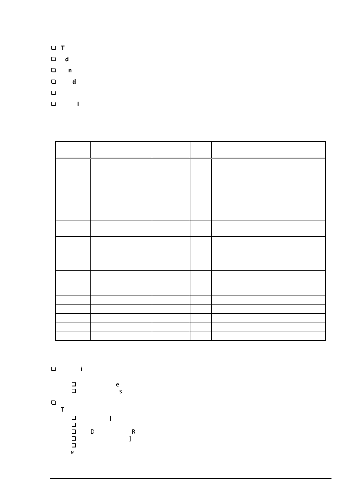
Pin No. Signal Name I/O Function Description
1 SCLK O Synchronous clock
2 CTS I Clear to send
3 TxD- O Transmit data 4 S.G. I Signal Ground
5 RxD- I Receive data 6 TxD+ O Balanced Transmit +
7 DTR O Data terminal ready
8 RxD+ I Balanced Receive +
Table 1-24. Connector Pin Assignment for Serial Interface
RS-423 compliant
Synchronous
Approximately 900 Kbps, 1.8 Mbps
Start bit 1 bit
Data bit 8 bit
Parity bit No parity bit
Stop bit1 bit
X-ON/XOFF, DTR protocol
8-pin mini circular connector
Apple System Peripheral-8 cable
Table 1-25. X-ON/X-OFF, DTR Protocol
State Buffer space X-ON/X-OFF DTR
Busy Less than 1024 bytes Send X-OFF code Off
Ready More than 2048 bytes Send X-ON code On
8
7
5
2
Figure 1-9.
Serial Interface Connector Pin Assignment
6
34
1
1-2
Rev. A
Page 28
EPSON Stylus COLOR 3000
1.4.3 Optional Interface
The EPSON Stylus COLOR 3000 supports an optional Type-B interface (Level 2) with the following
characteristics.
Reply message
In case of using Co-ax / Twin-ax I/F card
When ESC/P2 is selected:
Main type MTP48p, PW161cl10cpi, PRG(W0xxxx)rev, AP800ma,
Product name Stylus COLOR 3000
Emulation type ESCPL2-00
Entity type EPSONLQ2
When XL24E is selected:
Main type MTP48p, PW161cl10cpi, PRG(W0xxxx)rev, AP800ma,
Product name Stylus COLOR 3000
Emulation type PRPXL24-00
Entity type EPSONPRPXL24
In case of using an I/F card other than Co-ax / Twin-ax I/F card
When ESC/P2 is selected:
Main type MTP48p, PW161cl10cpi, PRG(W0xxxx)rev, AP800ma, SPD0fast
Product name Stylus COLOR 3000
Emulation type ESCPL2-00
Entity type EPSONLQ2
When XL24E is selected:
Main type MTP48p, PW161cl10cpi, PRG(W0xxxx)rev, AP800ma, SPD0fast
Product name Stylus COLOR 3000
Emulation type PRPXL24-00
Entity type EPSONPRPXL24
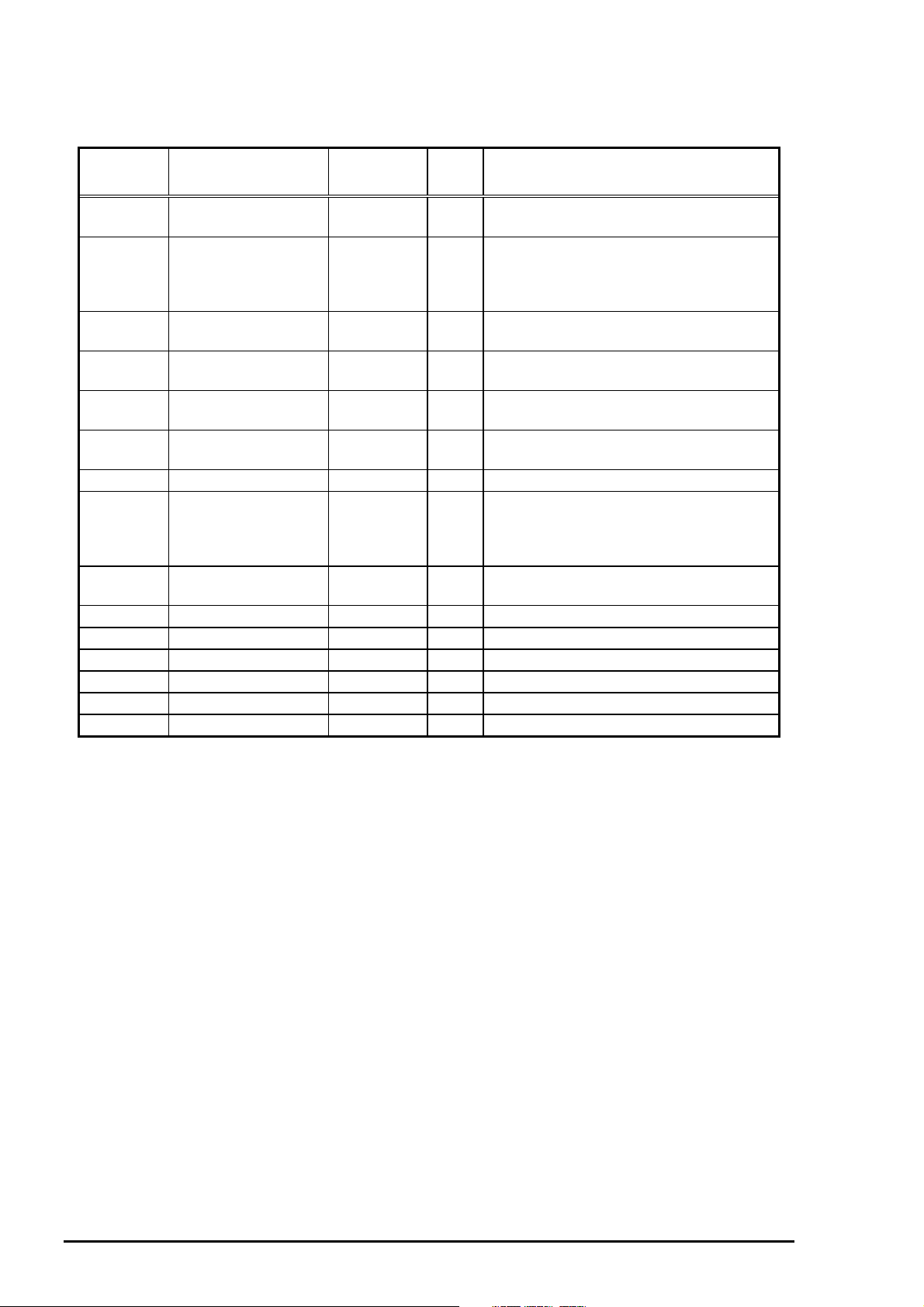
Table 1-26.Reply for Option Command
Option command No. command name Reply-A Reply-B
00h No Operation Accept None
01h Start Hard Ware Reset Accept Excute OK
02h Start Soft Ware Reset Reject
03h Send Main System Type Accept
04h Send Name Data Reject
05h Inquire Name Data Accept
06h Send Product Name Accept
07h Send Soft Ware Emulation Type Accept
08h Complete Buffered Data Accept Check Condition
09h Stop Procedure Reject Execute OK
0Ah Return Buffered Data Reject
0Bh Send Entity Type Accept
0Ch Send Status Accept
0Dh Quit Procedure Reject
0Eh Inquire ASCII Message Reject
0Fh Send ASCII Message Accept None
10h - 13h Unknown None
14h Inquire Emergency Message Accept Execute OK
15h Send Emergency message Accept
16h - 1Fh Unknown None
20h - FFh Reserved None
Rev. A
1-21
Page 29
Product Descriptions
2
Table 1-27. Supported Main Command and Sending Timing
Main Command Command name Sending Timing
01h Start Software Reset
04h Send Name Data
07h Inquire Software Emulation Name
0Eh Inquire ASCII Message
14h Inquire Emergency Reply
15h Send Emergency Message
Emergency Command
0X00 :Get device ID
0X01 :Get all status
Sending BDC-ST through DBIN register
When State-Reply is set “ON” by ST from Type-B I/F, sending BDC-ST through DBIN register is
started. When State-Reply is started, “Start” and “End” of BDC-ST characters are announced by
sending the Main command 0Eh.
/INIT signal on the standard parallel I/F
Type-B I/F option command : 01h
Cold Start
Type-B I/F command : 05h
Changing software Emulation Type
Writing to DBIN register
Reply for Emergency command
Receive Emergency Command
1.4.4 Prevention Hosts from Data Tr ansfer Time-out
Generally, hosts abandon data transfer to peripherals when a peripheral is BUSY continuously for dozens
of seconds. To prevent this kind of time-out, the printer receives data very slowly, several bytes par
minute, even the printer is in a busy state. This slowdown starts when the rem ainder of input buffer dr ops
under several hundreds of bytes. Finally, the printer is BUSY continuously when the input buffer is full.
1.4.5 Interface Selection
The EPSON Stylus COLOR 3000 has three types of interfaces: Parallel, Serial, and optional Type-B. Each
interface can be selected m anually or automatically. Both modes are selected thorough the def ault s etting
mode.
Manual selection
The interface selected through the default setting mode always prints out data from the host.
Automatic selection
Automatic interface selection is enabled in default setting mode. In automatic interface selection
mode, the printer is initialized to the idle state when it is powered on (*1) scanning which interfac e is to
receive data. Then the interface that rec eived data firs t is selec ted. When the host s tops data trans fer
and the printer is in the standby state for a number of seconds , the printer returns to the idle state. As
long as the host sends data or the printer interface is busy state, the selected interface is left as it is.
*1 No interface is selected in this state.
Interface State and Interface Selection
When an interface other than the parallel interface is selected, the parallel interface goes into the
BUSY state.
When the interface other than serial interface is selected, the serial interface sets the DTR signal
MARK.
When the printer is initialized and returned to idle state, the parallel interface goes into ready state
and the serial interface sets the DTR signal SPACE.
Note) An interrupt signal such as the INIT on the parallel interface is ignored while that interface is not
selected.
1.4.6 Printer language
ESC/P2
IBM XL24E
EPSON Remote
1-2
Rev. A
Page 30
EPSON Stylus COLOR 3000
3
1.5 Operation
This section describes the functions of each button on the control panel and LED printer status indicators.
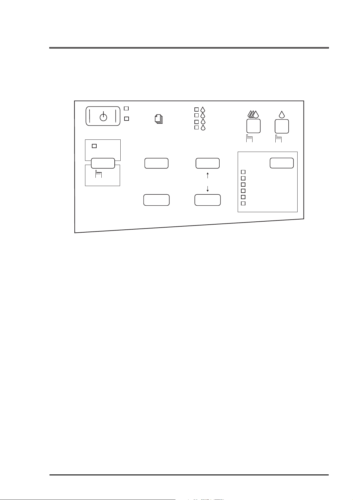
1.5.1 Control Panel
The control panel for this printer consists of 8 non-lock pushbuttons , 1 lock type pushbutton, and 13 LED
printer indicators for easy operation of the various printer functions. Refer to Figure 1-10.
Pause
Reset
5 Sec.
Operate
Paper Out
Ink Out
LF/FF
Load/Eject
Yellow
Magenta
Cyan
Black
Micro Adjust
Figure 1-10. Control Panel Appearance
Cleaning
3 Sec.
Media Type
Plain Paper
360 dpi Ink Jet Printer
Photo Quality Ink Jet Paper
Photo Quality Glossy Film
Ink Jet Transparencies
Other Media Selection Off
Cleaning
3 Sec.
Rev. A
1-2
Page 31
Product Descriptions
4
Panel Functions (Normal Usage)
Table 1-28. Panel Functions
Button Function
Operate Power On/Off Always
Pause Pause/Non-Pause Always
Pause
(5 seconds)
LF/FF LF/FF Pause/Standby
Load/Eject Load/Eject Pause/Standby
↑
Micro Adjust
Micro Adjust
↓
Cleaning (Black)
(3 seconds)
Cleaning (Color)
(3 seconds)
Media Type Selects paper type. Pause/Standby
Reset Pause/Standby
Micro adjust
(Forward feed)
Micro adjust
(Reverse feed)
Cleaning (Black) Pause/Standby
Cleaning (Color) Pause/Standby
Available
Condition
Pause/Standby See Note below.
Pause/Standby See Note below.
Note) TOF (Top Of Form) adjustment
When ”Micro adjust” is executed for the TOF position, the adjusted TOF position is memorized in
the EEPROM. TOF positions for the ASF, manual insertion and tractor are stored in the
corresponding addresses of EEPROM.
Tear off adjustment
When “Micro adjust” is executed for the tear off position, the adjusted tear off position is
memorized in the EEPROM.
Comment
At turning the printer off, the printer executes
capping function before the power down.
The function will be recognized with this
button held down for more than3 seconds.
The function will be recognized with this
button held down for more than 2 seconds.
The function will be recognized with this
button held down for more than 2 seconds.
Panel Functions with Power On
Table 1-29. Panel Function with Power On
Button Function Comment
Pause Enters the printer adjustment mode. Refer to Section 1.5.3.
LF/FF Enters LQ self-test print mode. Refer to Section 1.5.5.
Load/Eject Enters draft-self test print mode. Refer to Section 1.5.5.
Media type Enters the default setting mode. Refer to Section 1.5.2.
LF/FF
+
Load/Eject
Pause
+
LF/FF
+
Micro adjust ↓
Enters the hex-dump mode. Refer to Section 1.5.6
Performs EEPROM and IC reset. Initializes Timer IC and a part of
the EEPROM.
Note) ”+” means to press one button while holding down the other button(s).
CAUTION
The power switch is connected to the secondary side of the electrical circuit. Since it has a delay
circuit, voltage is still applied for the specified period of time after the printer power is turned off.
As long as the printer is plugged in, voltage is applied to the primary side of the electrical circuit.
Therefore be sure to unplug the printer before servicing or replacing the interface.
When the EEPROM is reset, the waste ink drain pads need replacing. This must be performed by
a qualified service person only. (See Chapter 3.)
1-2
Rev. A
Page 32

EPSON Stylus COLOR 3000
5
Indicators
This printer has 13 LED printer indicators, as shown in Table 1-30:
Table 1-30. Printer Condition and Printer Status (1)
LED Color Indication Status
Operate Green On Power on
Blinks Capping function in the power off
Paper Out Red On Paper out
Blinks Paper is jamming.
Pause Orange On Pause
Blinks The printer is in the ink sequence.
Ink Out (Yellow) Red On No yellow ink cartridge or ink out
Blinks Ink low
Ink Out (Magenta) Red On No magenta ink cartridge or ink out
Blinks Ink low
Ink Out (Cyan) Red On No cyan ink cartridge or ink out
Blinks Ink low
Ink Out (Black) Red On No black ink cartridge or ink out
Blinks Ink low
Media Type
Media Type
Media Type
Media Type
Media Type
Media Type
!" # $$
Note) Refer to Table 1-36 for more detailed conditions.
Green On Plain paper is selected.
Green On 360 dpi Ink Jet Printer is selected.
Green On Photo Quality Ink jet Paper is selected.
Green On Photo Quality Glossy Film is selected.
Green On Ink jet transparencies is selected.
Green On Paper type selection is neglected.
Rev. A
1-2
Page 33

Product Descriptions
6
1.5.2 Default Setting
Default setting mode enables users to c hange the default settings (initialization values). The set values
are stored in the EEPROM and are not lost after the printer is turned off. To reset the values to the factory
values, perform EEPROM reset operation or use the adjustment program described in Chapter 4.
1.5.2.1 Setting Method
See Figure 1-11 for the default setting method.
Start
Press the "Media Type" button
while turning on the printer.
The printer prints how to select the
language for "Usage of this mode"
and firmware version number.
1.Move through the languages listed
by pressing the "Micro Adjust "
button.
2.Set the language by pressing the
"Pause" button.
The printer prints the current
setting and "Usage of this mode"
in the selected language on the
currently loaded paper.
YES
Change the settings?
NO
Turn the printer off to save the new settings into the EEPROM.
Figure 1-1 1. Default Setting Flowchart
1. Select the menu by pressing the
"Micro Adjust " button.
2. Select the value for the selected menu
by pressing the "Media Type" button
More change?
NO
YES
CAUTION
Be sure to turn the printer off after the default setting operation is executed, since adjustment
values are not stored in the EEPROM until the printer is turned off.
The latest values set before power-off are stored in the EEPROM.
1-2
Rev. A
Page 34

7
1.5.2.2 Setting Menu
The printer enters default setting mode when you press the
printer. The menus available are shown Table 1-31.
Table 1-31. Default Setting Menus
Menu
Print direction*
2
Font
Pitch
I/F mode
Auto I/F wait mode
Software
Auto CR (IBM mode only)
A.G.M. (IBM mode only)
Character tables
Standard version
International character set
for Italic table
Auto line feed
Network I/F mode This mode is for network environment.
0 slash
Page length
Skip over perforation
Auto tear off
Banner mode *
3
Parallel I/F transfer rate
Note) 1. Underlined parameters in bold letters are factory default settings.
2. Refer to Table 1-32 and Table 1-33.
3. Refer to Table 1-34.
Auto
/ Bi-d / Uni-D
Roman / Sans Serif /
Courier
Roman T / Sans Serif H / Draft
10 cpi
Auto
10 seconds
ESC/P2
On /
On /
/ 12 cpi / 15 cpi / 17.1 cpi / 20 cpi / Proportional
/ Parallel / Mac Serial / Option
/ 30 seconds
/ IBM XL24E
Off
Off
Italic
PC 437
, PC 850
PC 860, PC 863
PC 865, PC 861
BRASCII, Abicomp
Roman 8, ISO Latin 1
PC 437 (Greek), PC 853
PC 855, PC 852
PC 857, PC 866
PC 869, MOZOAWIA
Code MJK, ISO 8559-7
ISO Latin 1T, Bulgaria
PC 774, Estonia
ISO 8859-2, PC 866 LAT
Italic USA
, Italic France
Italic Germany, Italic U.K
Italic Denmark, Italic Sweden
Italic Italy, Italic Spain 1
Off
On /
Off
: Used in usual environment
On: Used in network environment
0
/ 0 with slash
11 inch
On /
On
On /
Fast
/ 12 inch / 8.5 inch / 70/6 inch / other
Off
/ Off
Off
/ Normal
Media Type
Setting *
1
/ Prestige / Script/
EPSON Stylus COLOR 3000
button while turning on the
Rev. A
1-2
Page 35

Product Descriptions
8
Auto
Bi-D
Uni-D
Throughput and quality is better.
Throughput is the best.
Print quality may be down.
Throughput is worse.
Print quality is the best.
Table 1-32. Print Direction Mode Characteristics
Black and W hit e Pr inting YMCK Printing (color)
Throughput is better.
Color quality with special paper is
worse.
(Because Color correction depends on
the print direction.)
Throughput is the best.
Color quality with special paper is
worse.
(Because Color correction depends on
the print direction.)
Throughput is worse.
Color quality is the best.
Table 1-33. Printing Direction and ESC U Command
Character Mode
(for DOS)
ESC U 0 Auto Bi-D
Auto ESC U 1 Auto Uni-D
ESC U 2 Auto Auto
ESC U 0 Bi-D Bi-D
Default Bi-D ESC U 1 Uni-D Uni-D
Setting Mode ESC U 2 Auto Auto
ESC U 0 Uni-D Bi-D
Uni-D ESC U 1 Uni-D Uni-D
ESC U 2 Uni-D Auto
*: Printing direction is controlled by driver with Windows/Mac environment.
When the banner m ode is s elected by default setting or rem ote com mand, the f unction is as desc ribed in
Table 1-34.
Table 1-34. Vertical Print Position in the Manual Insertion
Auto Auto
Bi-D Bi-D
Uni-D Uni-D
Raster Graphics Mode
(for Windows / Mac) *
Function
Trigger
Command FF 1. Case that page length is set by
2. Case that page length is not set
ESC EMR No operation No operation
Switch FF Eject Advances to the top-margin position
Eject Eject (maximum 44 inches) Advances to the top-margin position
Data Over the page length
set by command
Over the paper
length
1. Case that page length is set by
2. Case that page length is not set
Eject Eject
Banner mode Off
(manual insertion operation)
ESC (C
→ Eject
by ESC (C
→ Advances to the top-margin
of the next page
ESC (C
→ Eject
by ESC (C
→ No operation
Advances to the top-margin position
of the next page.
of the next page.
of the next page.
No operation
Banner mode On
1-2
Rev. A
Page 36

9
1.5.3 Printer Adjustment Mode
The EPSON Stylus COLOR 3000 allows users to adjust the following items.
Table 1-35. Printer Adjustment Patterns
Pattern No. Items
1
1
1
2
2
*1 With an increment of 1/1,440 inch
*2 With an increment of 1/720 inch
Adjustment method
Pattern 1 Uni-d adjustment at 400 cps *
Pattern 2 Bi-d adjustment at 400 cps *
Pattern 3 Bi-d adjustment at 200 cps *
Pattern 4 Head gap adjustment between black and color to the cross
feed direction at 200 cps *
Pattern 5 Head gap adjustment between black and color to the cross
feed direction at 100 cps *
Start
EPSON Stylus COLOR 3000
Press the "Pause" button while
turning on the printer.
The printer prints the instruction
sheet on how to select the language.
1.Move through the languages listed
by pressing the "Micro Adjust "
button.
2.Select the language by pressing
the "Pause" button.
The printer prints the instruction
sheet on how to adjust the printer.
Adjust the patterns ?
NO
YES
1. Select the appropriate test by
pressing the "Micro Adjust " button.
2. Press the "Pause" button.
The printer prints the test patterns.
Select the most closely aligned pattern
by pressing the "Media Type" button.
Press the "Pause" button to set the selected
pattern number.
More adjustment ?
NO
Turn the printer off once to save the new settings into the EEPROM.
YES
Figure 1-12. Printer Adjustment Flowchart
Rev. A
1-2
Page 37

Product Descriptions
0
1.5.4 Printer Initialization
This printer has three initialization types: Power-on initialization, Operator initialization, and Software
initialization.
Power-on Initialization
Triggers Turning on the printer
Cold reset command (Remote RS command)
Actions performed
Initialize the printer mechanism.
Clears input data buffer.
Clears download character set.
Clears print buffer.
Sets default values.
Operator Initialization
Triggers Pressing the Pause button for 3 seconds
The printer recognizes the /INIT signal (negative pulse) of parallel interface.
Actions Performed
Clears input data buffer.
Clears download character set.
Clears print buffer.
Sets default values.
Software Initialization
Trigger ESC @ commend
Actions Performed
Clears print buffer.
Sets default values.
1.5.5 Self-test Printing Mode
This printer has the self-test printing mode to check several printer functions.
Trigger LQ mode: Pressing LF/FF button while turning on the printer
Draft mode: Pressing Load/Eject button while turning on the printer
Items checked
Function of the control circuit board
Function of the printer mechanism
Print quality
1.5.6 Hexadecimal Dump Function
Pressing the LF/FF and Load/Eject buttons while turning on the printer activates the hexadecimal dump
mode. Each line has Hexadecimal codes, along with their corresponding letters printed in the right
column. If a received c ode denotes an unprintable charac ter, a control code such as “.” (period) is pr inted
in the right column. This function enables users to check whether the data from the host is properly
transferred. Turn off the printer to exit the mode.
1.5.7 Monochrome Printi ng Mode
When the printer is in the ink end (color) condition, the black ink is subs tituted to continue to print. To
switch to monochrom e printing mode, turn off and bac k on the printer. This mode is als o selected by the
command “
ESC (K)
“. The Color select command “
ESC r
” is ignored in this mode.
1-3
Rev. A
Page 38
EPSON Stylus COLOR 3000
1.5.8 Error Condition
When any of the conditions lis ted below is detected, the printer goes into an error s tatus and the /ERRO R
signal goes LOW and the BUSY signal goes HIGH. On this condition, the printer accepts no data and
goes into a pause status automatically.
The CR moves abnormally. (Fatal error)
Paper ends or paper is jamming.
Release lever position is inappropriate for the paper path currently used.
No ink cartridge is installed or ink ends.
Maintenance is required.
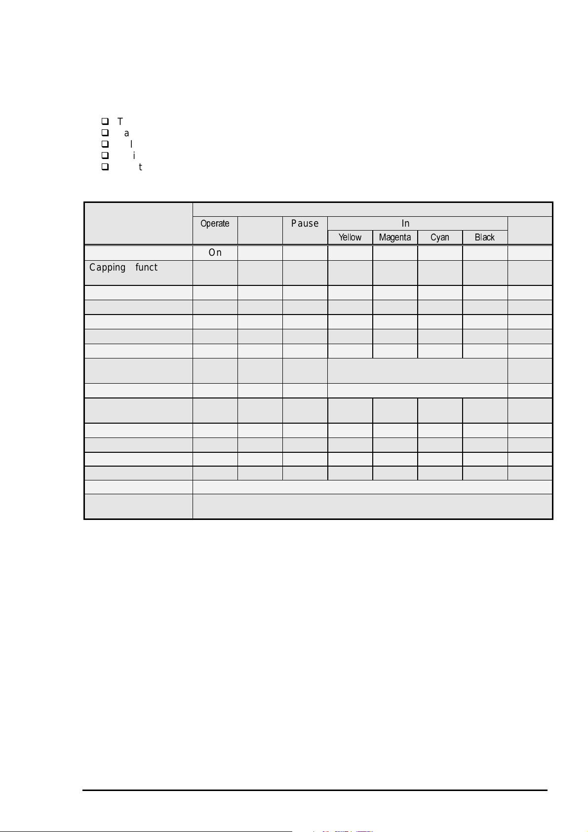
Table 1-36. Printer Condition and Panel Status (2)
LED Indicators
Printer Condition
Power on On
Capping function in
the power off
Data exit Blinks
Paper Out
Paper jam
Pause
During ink sequence
No color ink cartridge
or ink out
Ink Low (color)
No black ink c artridge
or ink out
Ink Low (black)
Lever error
Fatal error Blinks Blinks Blinks Blinks Blinks Blinks Blinks Blinks
Maintenance request Blinks Blinks Blinks On On On On Blinks
Panel reset function On for 1 second only.
Reset EEPROM and
Timer IC
Blinks
Note)
1. “” means no effect.
2. To recover from the fatal error, turn off and back on the printer or send the /INIT signal after eliminating
the trigger.
3. Maintenance request occurs when the wasted ink fills to capacity, and servicing is required. To clear
the error status, perform EEPROM reset. (See Table 1-29. Panel Function with Power On, Chapter 2
and Chapter 3.)
4. Refer to Table 1-30 for detailed conditions indicated by the Media type LED indicators.
Paper Pause Ink Out Media
Out
On
Blinks
On
Blinks
%& "' ( )
Corresponding color goes on.
Corresponding color blinks.
On
Blinks
On for 1 second only.
Type
Blinks
Rev. A
1-31
Page 39
Product Descriptions
2
1.6 Main Components
The main components of the EPSON Stylus COLOR 3000 are as follows:
Main control board C203 MAIN
Power supply board C172 PSB/PSE
Control panel bard C203 PNL
Printer mechanism M-4J60
Housing
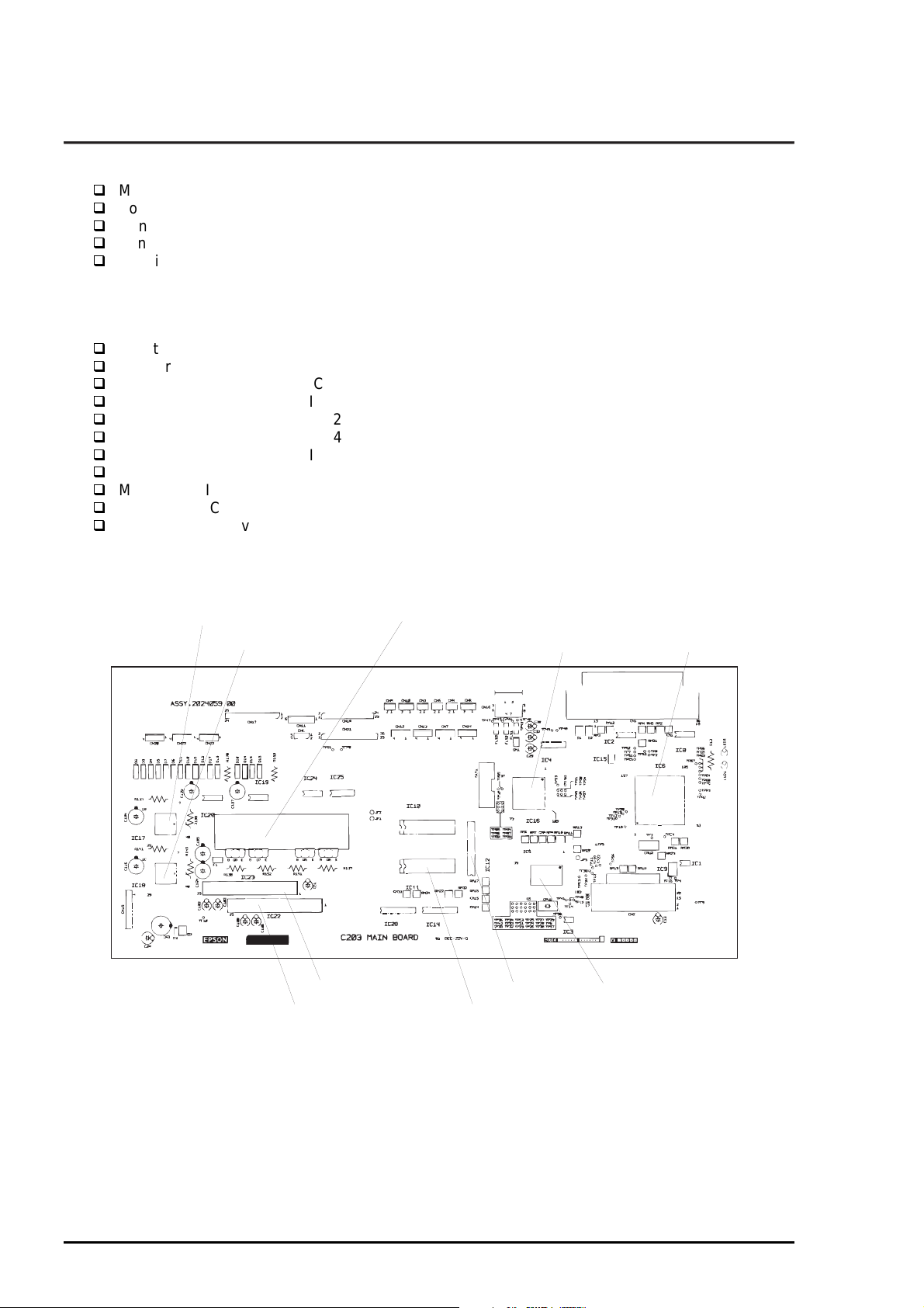
1.6.1 C203 MAIN Control Board
This board consists of the following:
16-bit CPU (IC5) (clock wave : 19.66Mhz)
Gate arrays B05B33 (IC6), B05B45 (IC16)
PROM (IC13)
CG-ROM (IC11)
DRAM (IC12),
SRAMs (IC14, IC28)
RESET ICs (IC3, IC9)
EEPROM (IC1)
Motor driver ICs (IC17, IC18) for the pump motor and PF motor
Motor driver ICs (IC19, IC20) for CR motor
Head common driver hybrid ICs (IC22, IC23).
PF Motor Driver CR Motor Driver
Pump Motor Driver
Color Head Common Driver
Black Head Driver
CG
Figure 1-13. C203 MAIN Board Component Layout
E05B45 (GA)
DRAM H8/2655 (CPU)
E05B33 (GA)
1-3
Rev. A
Page 40

EPSON Stylus COLOR 3000
3
1.6.2 C172 PSB/PSE Board
C172 PSB/PSE board, same as for Stylus COLOR 1500, consists of the transformer, switching FET,
regulator IC on the secondary circuit, diode bridge, fuse, and so on.
Fuse
Regulator IC
Transformer
Diode Bridge
Figure 1-14. C172 PSB/PSE Board Component Layout
Switching FET
1.6.3 Control Panel
The control panel for this printer consists of 9 pushbuttons and 13 printer LED indicators.
1.6.4 Printer Mechanism Unit (M-4J60)
The printer mechanism unit for this printer is composed of the CR m otor, PF motor, pump motor, paper
feeding mechanism, and ink system mechanism.
1.6.5 Housing
The housing for this printer consists of the upper housing, lower housing, printer cover, ink cartridge cover,
rear sheet guide, tractor unit, knob, adjust lever and release lever.
Rev. A
1-3
Page 41

Chapter 2
Operating Principles
2.1 Overview................................................................................................................2-1
2.2 Printer Mechanism Operating Principle .............................................................2-1
2.2.1 Printer Mechanism ................................................................................................................. 2-1
2.2.2 Printing Mechanism ............................................................................................................... 2-2
2.2.2.1 Printhead Structure ...................................................................................................2-2
2.2.2.2 Printing Process ........................................................................................................2-3
2.2.2.3 Printing Methods........................................................................................................2-3
2.2.3 Carriage (CR) Mechanism...................................................................................................... 2-4
2.2.4 Paper Feed Mechanism..........................................................................................................2-5
2.2.4.1 ASF (Auto Sheet Feeder) Mechanism ...................................................................... 2-6
2.2.4.2 Tractor Mechanism.................................................................................................... 2-7
2.2.4.3 Manual Feed Mechanism..........................................................................................2-7
2.2.5 Platen Gap (PG) Adjust Mechanism ..................................................................................... 2-8
2.2.6 Ink System............................................................................................................................... 2-9
2.2.6.1 Pump Mechanism.................................................................................................... 2-10
2.2.7 Capping Mechanism............................................................................................................. 2-11
2.2.7.1 Wiping/CR Lock Mechanism...................................................................................2-12
2.3 Electrical Circuit Operation Principles.............................................................2-13
2.3.1 C172 PSB/PSE Electrical Circuit Board.............................................................................. 2-13
2.3.2 C203 MAIN Control Board.................................................................................................... 2-15
2.3.2.1 Reset Circuits..........................................................................................................2-17
2.3.2.2 Sensor Circuits........................................................................................................ 2-17
2.3.2.3 CR Motor Driver Circuits ......................................................................................... 2-20
2.3.2.4 PF Motor Driver Circuit............................................................................................ 2-21
2.3.2.5 Printhead Driver Circuit ........................................................................................... 2-22
2.4 Ink System Management....................................................................................2-26
2.4.1 Ink System Operations......................................................................................................... 2-26
2.4.2 Counters................................................................................................................................ 2-27
Page 42

EPSON Stylus COLOR 3000
2.1 Overview
This chapter describes the operating principle of the printer mechanism and electrical circuit.
2.2 Printer Mechanism Operating Principle
2.2.1 Printer Mechanism
The printer mechanism of this printer is composed of the printhead unit, paper f eeding mechanism,
(arriage) mechanism and the pump mechanism. The bloc k chart for the printer mechanism is shown in
Figure 2-1. The printer mechanism has 3 motors: motor, PF (Paper Feed) motor and pump motor.
Tor que from the motor moves the in the column direction. PF m otor sends torque to load, f eed and
eject paper. The pump motor drives the pum p mechanism. The r eleas e lever s witches torque from the PF
motor side to the tractor side to feed continuous paper.
Release Lever
PF Motor
CR Motor
Disengage Mechanism
Black
Printhead
Pump Motor
Color
Printhead
Figure 2-1. Printer Mechanism Block Diagram
Push Tractor Mechanism
Paper Feed Mechanism
ASF Mechanism
(For Cut sheet only.)
CR Unit
Pump Mechanism
Rev. A
2-1
Page 43

Operating Principles
2
2.2.2 Printing Mechanism
The printing method used for this printer is On-dem and ink jet, sam e as for other EPSON ink jet printer s.
However, use of the new type of printhead improves print quality and speed. The printing m echanism has
2 parts: printhead and ink cartridge which is filled with ink.
2.2.2.1 Printhead Structure
The printhead for this printer has the black and color printheads. The structures of the printheads are
basically the same except for the nozzle configuration. The blac k printhead, us ed for the black ink only, is
composed of 128 nozzles (32 nozzles for each of 4 rows), while the color printhead, composed of 3
printheads for Magenta, Cyan and Yellow, has 64 nozzles (32 nozzles for each of 2 rows) for each color.
Printhead Driver Circuit Board
Nozzle Plate
To the ink cartridge.
Piezo
Cavity
2-
Nozzle
Figure 2-2. Printhead Structure
Rev. A
Page 44
EPSON Stylus COLOR 3000
3
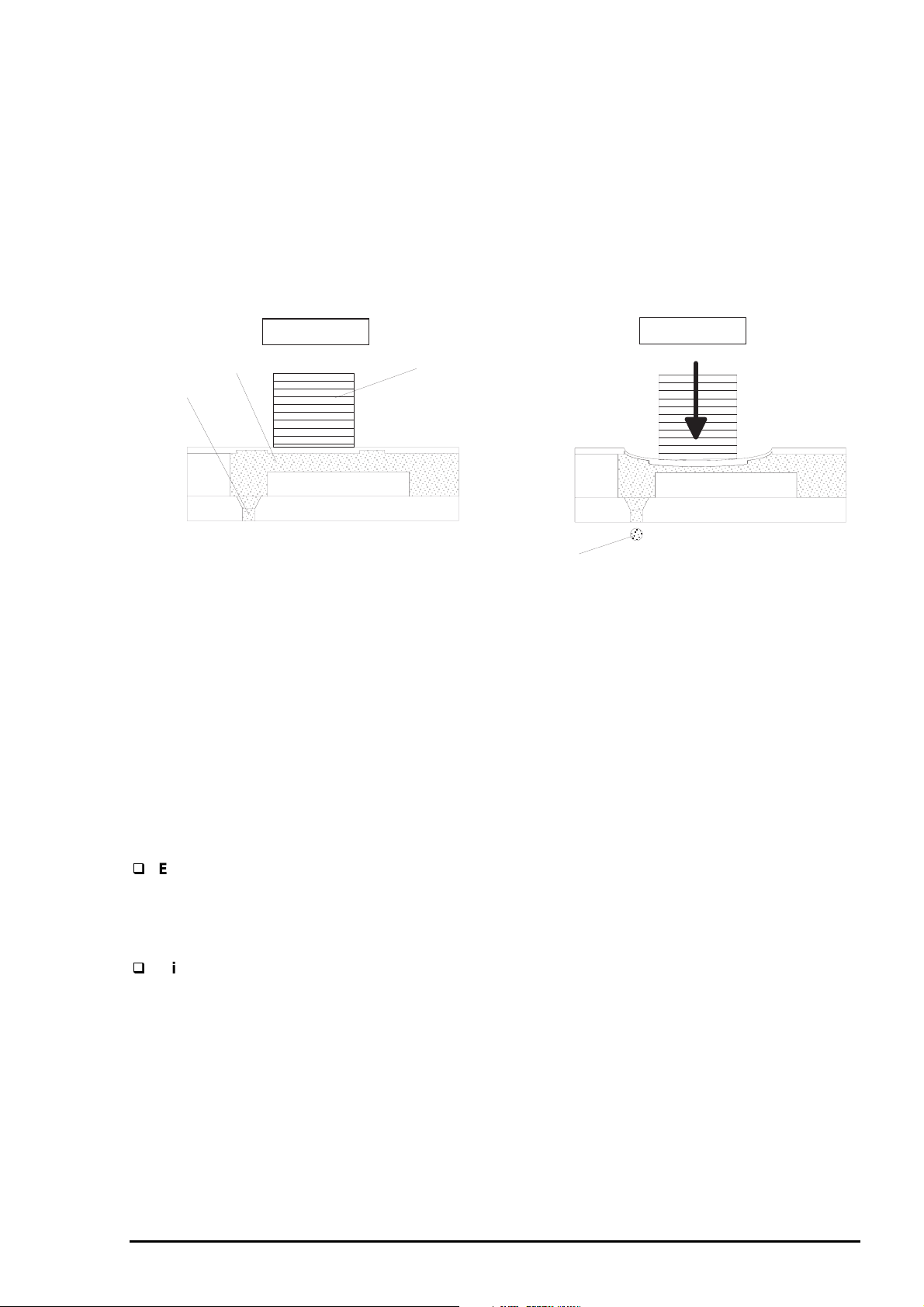
2.2.2.2 Printing Process
Steps bellow describe how the ink is ejected from each nozzle with the on-demand ink jet system.
Step 1>Normal state
<
No print signal is applied to the PZT (Piezo electric element). In this state, the PZT does not displace and
no pressure is added to the ink inside the c avity. Therefore the pressure in the cavity is k ept at a cons tant
level.
Step 2>Ejecting state
<
Print signal is applied to a specific nozzle via the head driver circuit to activate the PZT of the nozzle. The
voltage which activates the PZT is produced in the com mon dr iver circuit on the c ontrol board. When the
voltage is applied to the PZT, the PZT displaces and the pressure in the c avity changes. Then the ink
ejects as a result.
Ejecting State
Cavity
Normal State
Piezo
Nozzle
Ejected Ink
Figure 2-3. Printing Operation States
When no m ore print signal is applied to the PZT, the PZT recovers f rom the displaced s tatus. With this
process, the cavity also returns to its normal size, which brings the pressure negative. The negative
pressure in the cavity then absorbs the ink from the cartridge to fill the cavity with the ink again for the next
printing motion. The ink which was not used for printing adheres on the nozzle surface and increases
viscosity in the nozzles, and it causes printing malfunction. Theref ore the ink is per iodically absorbed and
wasted into the waste ink drain pads by the pump mechanism. Ink viscosity varies depending on the
temperatures around the printhead. Since the c hange in the ink viscosity leads to decline in print quality,
the thermistor is attached to the color printhead to keep the drive voltage at a proper level based on the
detected printhead temperature.
2.2.2.3 Printing Methods
EPSON micro dot printing
Both black and color printings can be performed in the normal dot printing mode and EPSON micro
dot printing mode. In the normal dot printing mode, the printer uses less ink to create sharper dots.
Therefore the gradation range is expanded in more delicate tone. This mode is available when the
1440X720-dpi paper or glossy film is selected.
Micro weave printing
In this mode, the printer prints 1 line with multiple passes by using specific nozzles for each pass. The
paper is also fed in smaller increments for this operation. Since this mode eliminates white banding
problem, the graphic images quality is improved. However, decrease in paper feed speed is inevitable.
The Micro Weave printing can be selected through the printer driver.
Rev. A
2-
Page 45

Operating Principles
4
2.2.3 Carriage () Mechanism
The mechanism is composed of the unit, timing belt, guide shaft, paper eject frame, (Home
Position) sensor and motor. The motor sends torque to the tim ing belt to move the unit in the
both right and left directions along the paper eject frame and guide shaft. A stepping motor us ed for
the motor enables the unit to move and stop at any position. The is primarily detected at the
home position by the sensor when the printer is turned on and its position is then controlled by the
open loop. Table 2-2 and Table 2-3 show the specification for the motor and the motor drive term s,
respectively.
Table 2-1. Motor Specification
Item Description
Motor type 4-phases / 200-pole / Hybrid type stepping motor
Drive voltage
Coil resistance
Excitation mode
Drive frequency 480 to 9600 Hz
Minimum step 0.202 mm (2-2 phase drive)
42 VDC ± 5% (The voltage applied to the driver)
5 Ω ± 7% (at 25° C per 1 phase)
Bipolar drive
2-2 phase, 1-2 phase, 1-2, 21-2 phase, 41-2 phase
Constant current drive
0.106 mm (1-2 phase drive)
0.053 mm (1-2 phase drive)
0.026 mm (21-2 phase drive)
0.013 mm (41-2 phase drive)
Table 2-2. CR Motor Drive Terms
Print
mode
Print speed Acceleration1Acceleration
2
Constant Deceleration1Deceleration
2
Draft 400 cps 0.91 0.91 0.63 0.91 0.91
LQ 200 cps 0.91 0.91 0.49 0.63 0.63
SLQ 100 cps 0.63 0.63 0.49 0.63 0.63
CR Motor
CR Unit
Timing Belt
Sub Pulley
Pulley
HP Sensor
Paper Eject Frame
CR Guide Shaft
Figure 2-4. CR Mechanism
2-
Rev. A
Page 46

EPSON Stylus COLOR 3000
5
2.2.4 Paper Feed Mechanism
The paper feed mechanism of this printer consists of the integrated ASF (Auto Sheet Feeder) mechanism,
tractor mechanism, PF (Paper Feed) motor, front/rear PE (Paper End) sensors, PF roller, paper guide
mechanism, paper eject unit, and PF motor drive disengage m echanism. The torque fr om the PF motor
drives the paper load mechanism, paper f eed mechanism and paper ej ect mechanism . While the pr inter
is not printing, the PF motor drive disengage mechanism switches the torque sent from the PF motor to
the ASF mechanism, which depends on the position. W hile the paper feed mechanism is driven, the
torque from the PF m otor is transmitted via PF motor pinion gear and disengage gear to the PF roller,
where the torque splits in 2 directions: one is to the paper ej ect mechanism via the gear tr ain in the paper
guide assembly and the other is to the ASF mechanism via the tr ansmission gear. The tractor drive gear
train is set at the left end of the PF roller. Table 2-3 and Table 2-4 shows the specification for the PF motor
and PF motor drive terms, respectively. Figure 2-5 illustrates the paper feed mechanism.
Table 2-3. PF Motor Specification
Item Description
Motor type 4-phases / 96-pole / Hybrid type stepping motor
Drive voltage
Coil resistance
Connection Bipolar
Excitation mode 2-2 phase, 1-2 phase, W1-2 phase constant current drive
Minimum step 1/720 inch / step (2-2 phase drive)
42 VDC ± 5% (The voltage applied to the driver)
10 Ω ± 10% (at 25° C per 1 phase)
Table 2-4. PF Motor Drive Terms
Operation
mode
Paper feed
Acceleration Constant Deceleration Stand-by
0.9/0.9 0.9 0.75/0.75 0.6
ASF Feed 0.9/0.9 0.9 0.75/0.75 0.6
Pump driven
Pump driven
(slow)
/0.9
/
0.9 0.9 0.6
0.9
/
0.6
Note) Double 1-2 phase drive / 2-2 phase drive
Tractor Disengage Gear
ASF Transmission Gear
To the tractor mechanism.
To the ASF mechanism.
PF Drive Roller
Paper Eject Roller
Paper Eject Out Roller
PF Motor Pinion Gear
PF Motor
Paper Eject Drive Unit
Figure 2-5. Paper Feeding Mechanism
Rev. A
2-
Page 47

Operating Principles
6
2.2.4.1 ASF (Auto Sheet Feeder) Mechanism
When the printer is not printing, the motor drive disengage m echanism switches the torque sent f rom
the PF motor to the LD rollers in the
of the unit. The roller shaft has 2 cams on the right and left ends. They push down the paper
support to make the paper surf ace com e in contact with the rollers. The one way clutch rotates the
roller in the specified direction to load paper. Once the paper is loaded, the torque from the planetary gear
is disengaged and the paper is then transported by the paper feed mechanism.
Cam
Paper Support
mechanism via the planetar y gear based on the detected position
Cam
ASF Mechanism
LD Rollers
Paper
One-way Clutch
ASF Transmission Gear
PF Motor Pinion Gear
PF Drive Roller
Front PE Sensor
PF Motor
Figure 2-6. ASF Mechanism
2-
Rev. A
Page 48

EPSON Stylus COLOR 3000
7
2.2.4.2 Tractor Mechanism
Tor que sent from the motor to the roller is transmitted to the tractor gear via dis engage m echanism
operated with the release lever. When the release lever is set to the tractor side, the release sensor
detects the condition and torque transmission to the ASF mechanism is cut off as a result.
Tractor Gear
Tractor Disengage Gear
PF Motor Pinion Gear
Release Lever
Rear PE Sensor
PF Roller
PF Motor
Figure 2-7. Tractor Mechanism
2.2.4.3 Manual Feed Mechanism
The printer loads cut sheet and roll paper in the r ear paper slot. When the rear sensor detects the
paper, the unit leaves the ASF paper feed position. Theref ore the paper is manually loaded even if
paper is set in ASF. This mode allows use of types of paper that differs from the one set in ASF.
Rev. A
2-
Page 49

Operating Principles
8
2.2.5 Platen Gap () Adjust Mechanism
The adjust mechanism , located at the top right of the printer cover, allows the user to set the proper
platen gap (distance between paper and nozzle surface) for the paper thicknes s to prevent ink sm udging.
The adjustment mechanism consists of the adjust lever, guide shaft, and parallelism adjust
bushings. Switching the lever from “0” to “ 1” turns the guide shaft which joins to the lever. Since the
joint for the parallelism adj ust bushing and guide shaft has an eccentricity toward the guide shaft, the
guide shaft moves from or toward the platen as the lever m oves. With this m ovem ent, the platen gap also
changes from wide to narrow or vice versa.
Table 2-5. Platen Adjust Lever Positions
Paper Type Adjust lever Position PG Adjustment Value
Cut Sheet,
Label, Continuous paper
Envelope ,Card, Index card Front + 0.7 mm
Parallelism Adjust Bushing
Sheet,
0
(Rear)
Rear 0
PG Adjust Lever
+
(Front)
Printhead
Eccentricity
CR Guide Shafts
Figure 2-8. Platen Gap Adjustment Mechanism
Platen Surface
Platen Gap
2-
Rev. A
Page 50

9
2.2.6 Ink System
The ink system for this printer is composed of the following mechanisms.
Ink cartridge
Pump mechanism
Capping mechanism
Waste ink drain pads
Wiping mechanism
Figure 2-9 shows the block chart of the ink system. flowchart
Ink Cartridges
Cleaner Head for
Black and Color Inks
CR Unit
EPSON Stylus COLOR 3000
Air Valves
Pump 2
Pump 1
Clutch Unit
Combination Gear
Pump Unit
Pump Motor
Gear
Waste Ink Drain Pads
Figure 2-9. Ink System Mechanism
Rev. A
2-
Page 51

Operating Principles
0
2.2.6.1 Pump Mechanism
The pump mechanism , com posed of the pump m otor and pum p unit, absorbs viscous ink in the printhead
nozzles and drains it to the waste ink drain pad through the cap. Since this printer has only one pum p, it
uses the pump for both black and color inks by alternating the rotational direction of the pump motor.
When the pump m otor rotates forward *
backward rotation *
2
. The pump unit is com posed of the pulley, tube and 2 rollers, as shown in Figure 2-
10. To dr aw ink, the pulley rotates the rollers which squeeze the tube reducing volume as they move to
produce negative pressure. As a result, the ink is vacuum ed and drained into the waste ink drain pads by
the pressure produced through the operation.
*1 The direction in which the paper is fed.
*2 The direction in which the paper is fed back.
Pulley
Ink Draining
1
it absorbs black ink . On the other hand, it absorbs color ink with
Ink Drawing
Ink Drawing
Pump Motor (Backward):Color Ink Drawing
Pulley
No Ink Drawing
No Ink Draining
Pump Motor (Backward):No Black Ink Drawing
Ink Draining
Pump Motor (Forward):Black Ink Drawing
No Ink Draining
No Ink Drawing
Pump Motor (Forward):No Color Ink Drawing
Figure 2-10. Pump Operation
Table 2-6. Pump Motor Specification
Item Description
Motor type 4-phases / 48-pole / PM type stepping motor
Drive voltage
Coil resistance
42 VDC ± 5% (The voltage applied to the driver)
7.7 Ω ± 10% (at 25°C per phase)
Connection Bipolar
Excitation mode
2-2 phase, 1-2 phase, W1-2 phase,
Constant current drive
Drive frequency 281 to 1250 Hz
Drive current
825 mA (at fast absorption)
500 mA (at slow absorption)
2-1
Rev. A
Page 52

EPSON Stylus COLOR 3000
2.2.7 Capping Mechanism
Ink around head nozzles loses moisture If they are left exposed while the printer is in non-printing or
power off status. Therefore the printheads must be capped to avoid increasing viscosity due to dried
nozzles. The caps are individually equipped for the black and color printhead. W hen the moves right
from the home position, the c ap holder also shif ts right and strik es the right f ram e. This m otion opens the
air valve and the air in the cap is release. To resume printing, the moves right from the home pos ition
to strike the right fram e with the cap holder so that the air valve opens . T his operation brings the negative
pressure in the cap back to nor m al and the goes back to the home pos ition. Since the power s witch of
this printer uses the secondary power-on circuit, the printer power stays on to allow the printer to complete
the capping operation even if the printer is turned off during the operation.
Black Ink Printhead
Cap2
To the waste ink drain pads
Valve Spring
Carriage
Color Ink Printhead
To the waste ink drain pads
Air Valve
Air Tube
Cap Holder
Cap1
Capping Unit Frame
Figure 2-1 1 . Capping Mechanism
Rev. A
2-1 1
Page 53

Operating Principles
2
2.2.7.1 Wiping/CR Lock Mechanism
The wiping operation removes the ink and dust adhered around the nozzles. This is operated during a
cleaning sequence. W hen the pum p m otor r otates back ward, the torque s ent via the head c leaner ( wiper)
drive gear and the clutch moves the head cleaner to the printhead route. The unit then begins to move
right and left to wipe the nozzle surface against the head cleaner. When the wiping operation is complete,
the pump motor rotates f orward to move back the head cleaner. Only one cleaner head is used for the
both black and color printheads. The head cleaner also functions as the lock mechanis m. When the
printer power is off, it keeps the unit from shif ting left (to the printing side). T he switch lever locks the
at the right end by joining with the disengagement mechanism. With this mechanism, the unit
remains in the capping position while transported.
CR
Head Cleaner
Head Cleaner Lever
Printhead
Pump Motor
Gear Train
Disengage Mechanism
Figure 2-12. Wiping/Carriage Lock Mechanism
Pump Gear/Clutch
<Wiping Mechanism>
Switch Lever
CR
Head Cleaner Lever
<CR Lock Mechanism>
2-1
Rev. A
Page 54

EPSON Stylus COLOR 3000
3
2.3 Electrical Circuit Operation Principles
This printer consists of the following circuit board:
C203 MAIN board
C178 PSB/PSE board
C203 Panel board
Head driver circuits are directly attached to the black and color printheads. Figure 2-13 shows the block
diagram of the electrical circuit.
C203 PNL
C172 PSB/PSE
C203 MAIN
+5VDC
+42VDC
Printer Mechanism Unit
CR/PF/Pump
Motors
CR Unit
Color Head
Driver Circuit
Black Head
Driver Circuit
Figure 2-13. Electrical Circuit Block Diagram
2.3.1 C172 PSB/PSE Electrical Circuit Board
The output voltages of the PSB/PSE board are as shown in Table 2- 7. Since the electrical circuit of this
printer is in a secondary circuit, the delay timer can be used to allows the printer to execute the capping
operation after the printer power is turned off. This is to prevent ink clogging or smudging caus ed by the
exposed condition of the printhead.
Table 2-7. DC Voltage Distribution
VDC Application
+42 V
+5 V
motor/ motor
Printhead common voltage
C
MAIN control board (logic)
Sensors
Control panel, Head nozzle selection
The electrical circuit of this board us es the
(Ringing Choke Converter) switching regulator. voltage
is first input to the filter circ uit for higher harm onics absorption and is converted into voltage thorough
the rectifier and smoothing circ uits. The voltage is then input to the switching circuit. These operations
are followed by the transformer which generates and stabilizes +42
produced +42
is then converted into the stable +5
by the regulator IC. The
in the secondary side. The
on the
!"#
board monitors the on/off signal from the power switch on the control panel. W hen the power switch is
turned off, the
sends the
signal (PSC) to the electrical circuit. The electrical board has a
delay circuit (ZD86, C82 and Q84) to delay the power off. The delay period depends on the electrolytic
capacitor. It continues to output +5 V and +42 V to keep the main circuit switch on the primary side active
until all electric charge is discharged. T he minim um delay period is normally 30 seconds, which ,however,
varies depending on the capacitor size.
Rev. A
2-1
Page 55

Operating Principles
4
Figure 2-14 illustrates the electrical circuit diagram.
Full Wave
Rectifier
Circuit
Filter
Fuse
AC Input
Primary Circuit
Smoothing
Circuit
Switching
Circuit
(Q1)
Half Wave
Rectifier
Circuit
Photo-coupler
PC1
+42 V
Circuit
+42 V
Protection Circuit
(Q81, Q82)
+42 V
Protection Circuit
(ZD52, ZD53, ZD87, Q82, Q83)
+5 V
Protection Circuit
(ZD53, Q82)
Secondary Circuit
Chopping
Regulator
(IC51)
Line Detector
(ZD51, 81 to 86)
Line Over Current
Line Over Voltage
Over Voltage
+42 V
+5 V
Power Off Delay Circuit
(ZD88, C84, Q84)
Power Off Signal
Figure 2-14. Power Supply Circuit Diagram
+5 VDC line over voltage protection circuit
The output voltage level of the 5 V line is monitored by a Zener diode (ZD53). If the voltage level
exceeds 9 V, the status is fed back to the primary switching circuit through the transistor (Q82) and
photocoupler (PC1) to cut off the +42 V line to the regulator (IC51).
+5 VDC line constant voltage control circuit
Voltage at +5 VDC line is controlled by the regulator IC (IC51). When the abnormal voltage at +5 VDC
line is detected, the status is input to the internal comparator of the regulator to control the voltage.
+42 VDC line over voltage protection circuit
The output level of the +42 VDC line is monitored by the 2 Zener diodes ZD52 and ZD87. When the
output level of the +42 VDC line exceeds +48 V, the switching FET operation on the primary side is
stopped via the thyristor (CY52), transistor (Q81) and photocoupler (PC1).
+42 VDC line constant voltage control circuit
Voltage at the +42 VDC line is monitored by the Zener diodes (ZD51, ZD81−ZD86). This circuit feeds
back the output voltage level status through photocoupler (PC1) to the primary switching circuit to
control the on/off time of the switching FET to constant output voltage level.
+42 VDC line overcurrent protection circuit
The output current is monitored by the transistors Q81 and Q82. When the output current is
abnormally low , the status is assumed to be a short circuit and the information is fed back to the
primary circuit to stop the switching FET operation.
2-1
Rev. A
Page 56

EPSON Stylus COLOR 3000
5
2.3.2
This printer uses
Table 2- 8 and Figure 2-15 s how the allocated functions for m ajor com ponents and the m ain control circ uit
block diagram, respectively.
MAIN Control Board
MAIN for the main control circuit board. It consists of the following:
16-bit
H8S/2655 (IC5) Runs at 19.66 MHz
2 gate arrays E05B33 (IC6) Manages interfaces, motors and printheads.
E05B45 (IC16)
P-ROM, DRAM and MROM
Drivers Produces common voltage for printheads
Drives motors.
Table 2-8. Location and function of the Major Components
IC Location Function
CPU IC5
Gate Array IC16
IC6
DRAM IC12
SRAM IC14, IC28
C.G. ROM IC1 1
P-ROM IC13
Optional ROM
EEPROM IC1
Timer counter IC IC2
Reset IC IC9
Common driver IC IC22
Driver IC17
IC7, IC10
IC3
IC23
IC18
IC25
IC19, IC20
16-bit
Runs at 19.66 MHz
Controls the printer at the gate arrays IC5 and IC6
according to the program in P-ROM.
Monitors the printhead temperature.
Controls the I/F for the control panel.
Controls the motor.
Manages the sensors.
Controls the parallel I/F.
Controls the serial I/F.
Controls Type-$ I/F.
Controls the motor.
Controls the pump motor.
Controls black and color printheads.
Manages buffers, work area in the
Manages input buffer.
Manages C.G. (Character Generator).
Manages printer control program.
For optional fonts and (not attached as a
standard item.)
Stores values for the default settings and other
values.
Manages timers for the ink system.
Outputs a reset signal to the logic line (+5).
Outputs a reset signal to the power line (+42).
Produces common voltage for the black printhead.
Produces common voltage for the color printhead.
Drives the motor.
Drives the pump motor.
D/A converter for motor control
Drives the motor.
%
Rev. A
2-1
Page 57

Operating Principles
6
Type-B
I/F
PW, PQ, PWS
Sensors
Head
Temperature
+42V
Power Line
Reset IC
M51955BFP
(IC3)
+5V
Logic Line
Reset IC
RST592D
(IC9)
C.G.-ROM
(8M)
(IC11)
P-ROM(8M)
(IC13)
CPU
H8S/2655
(IC5)
+5V
Lithium Battery
EEPROM
AT93C56
(IC1)
+5V
DRAM(16M)
(IC12)
Timer
Counter IC
RTC-4543SA
(IC2)
SRAM(256K)
(IC14)
CLK
SD I/O
SRAM(256K)
(IC28)
GA
E05B45
(IC16)
GA
E05B33
(IC6)
Optional ROM
(IC7, IC10)
Data Bus
Address Bus
CR Motor Control
Control Panel
Sensors
Black/Color Printhead
Control Signals
PF Motor
Control Signal
Pump Motor
Control Signal
Parallel I/F
Serial I/F
+42VDC
+5VDC
PSC
From IC6
From IC6
From IC16
From IC6
From IC6
Carriage
Black/Color Printhead
Common Driver Circuit
Nozzle Selection Signal
Nozzle
Selection IC
Nozzle
Selection IC
CR Motor Driver Circuit
A3953 (IC19, IC20)
PF Motor
Driver Circuit
M
M
CR Motor
PF Motor
UDN2917EB (IC17)
Pump Motor
Driver Circuit
M
Pump Motor
UDN2917EB (IC18)
Figure 2-15. Control Circuit Block Diagram
Black Printhead
128 Nozzles
Color Printhead
64 Nozzles
for each color
2-1
Rev. A
Page 58
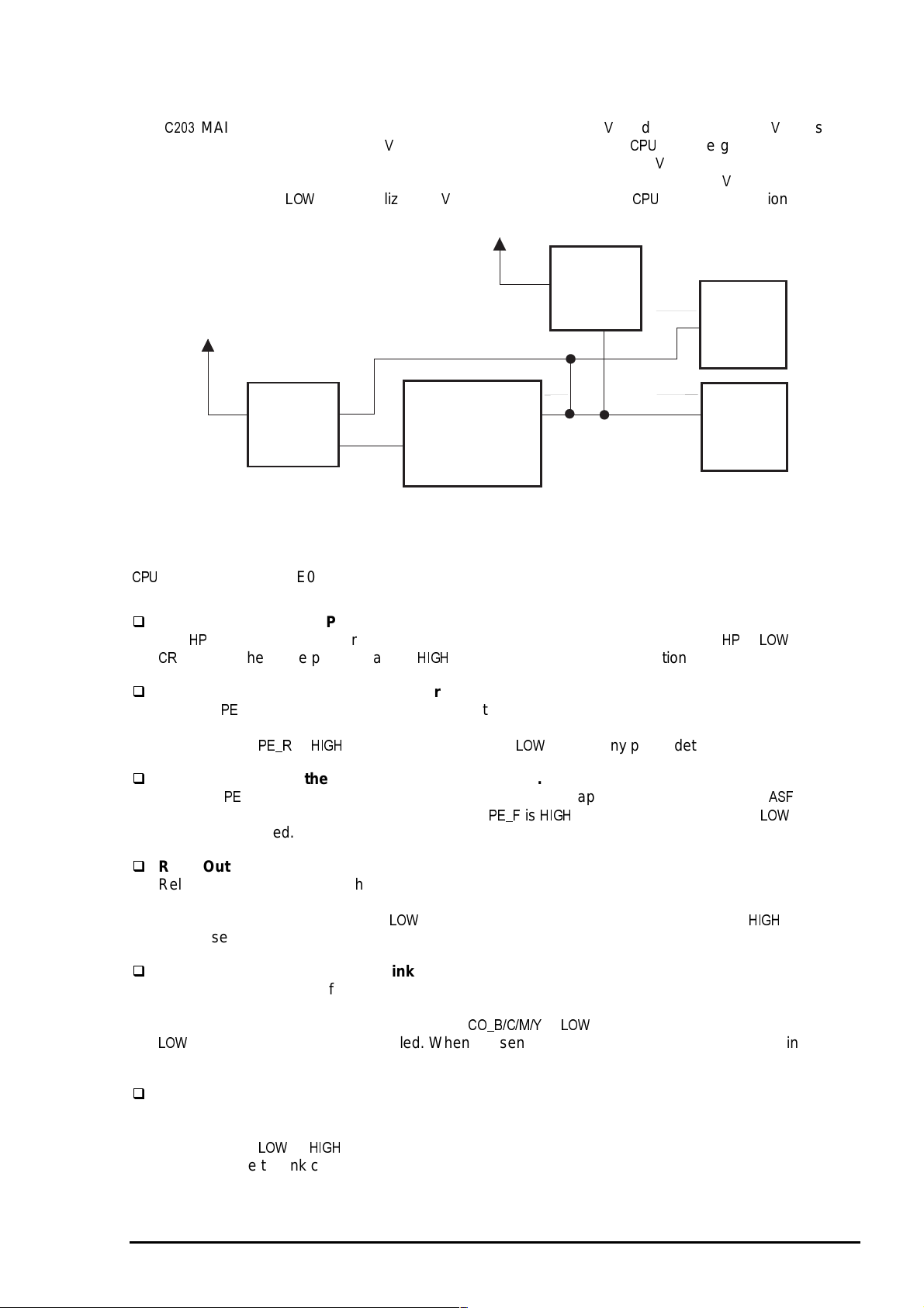
EPSON Stylus COLOR 3000
7
2.3.2.1 Reset Circuits
The
MAIN board contains two reset circuits: for logic line (+5 ) and power line (+42 ). Reset IC
M51955BFP (IC3) monitors the +42 line. It outputs /NMI signal to the
the power line for the motors when the voltage level drops below 33.2 . Reset IC RST592D (IC9)
monitors the +5 V line and sends low pulse when the voltage level drops below 4,2 . While the printer
power is on, it outputs
until stabilized +5 is produced to ensure the
+5V
RST592D
(IC9)
+42V
M51955BFP
(IC3)
VOUT
and the gate array to cut off
’s proper operation.
RESET
GA
E05B45
(IC16)
NC5
OUT
NMI
RES
CPU
H8S/2655
(IC5)
RESET
GA
E05B33
(IC6)
Figure 2-16. Reset Circuit Block Diagram
2.3.2.2 Sensor Circuits
and the gate array E05B45 (IC 16) monitor printer condition refer ring to the signals fr om 13 s ensors
described below
HP : Output from the HP(Home Position) sensor.
The sensor for this printer uses the reliable photo interrupter system. the signal is
unit is at the home position, and is
PE_R : Output from the rear PE (Paper End) sensor.
"
when it is not at the home position.
The rear sensor, attached to the rear part of the paper path, detects paper presence condition for
continuous paper or cut sheet set in the rear paper slot. A mechanical switch is used for this sensor
and the signal
PE_F : Output from the front PE (Paper End) sensor.
&
is
"
with paper detected and
without any paper detected.
The front sensor, located in the paper guide unit, detects paper presence condition for
sensor uses a mechanical switch and the signal
&
is
"
with paper detected and is
any paper detected.
without
when the
. This
REL : Output from the release sensor.
Release sensor is built into the rear part of the left frame in the printer mechanism. It determines
whether the release lever is set to the cut sheet side (friction mode) or to the continuous paper side
(tractor mode). The signal REL is
when the lever is set to the friction mode and is
"
when the
lever is set to the tractor mode.
CO_B/C/M/Y :Output from each ink cartridge sensor.
The ink cartridge sensor for each color is individually attached to the ink cartridge holder in the printer
mechanism. It determines whether the corresponding ink cartridges is installed or not. A mechanical
switch is used for this sensor and the signals
when the cartridge is not installed. When the sensor detects no cartridge condition, the ink
&$!'
is
when the cartridge is installed and is
consumption counter is reset.
IE_B/C/M/Y : Output from each ink end sensor.
The ink end sensor for each color, individually attached to the ink cartridge holder in the printer
mechanism, detects ink end condition*. It uses the mechanical switch system and the signal
IE_B/C/M/Y is
or
"
on the ink left or end condition, respectively. If the ink end condition is
detected while the ink cartridge is detected by the ink cartridge sensor, the ink consumption counter is
reset.
Note) The ink end sensor detects an ink end condition when the remainder of the ink drops to 5 % of
the capacity.
Rev. A
2-1
Page 59

Operating Principles
8
Thermistor
Thermistor is attached onto the color printhead to monitor the temperatures around the printhead. It
functions to avoid change in ink viscosity, which affects printing result. The signal output from the
sensor is directly transmitted to the analog port of the
ASF_PW : Output from the ASF PW (Paper Width) sensor.
The ASF sensor uses a sliding potentionmeter. (The maximum resistance :10kΩ.) It is attached to
the left edge guide in the ASF hopper assembly. By aligning the left edge guide to the paper, the
sensor actuator runs along the grooves at the bottom of the stacker. The length measured by the
actuator is converted into ohms which corresponds to the paper width, then the value is transferred to
the analog port of the
(See Table 2-9.) If the detected paper width does not match the width for the selected page size, the
printer ignores the data which does not fit in the printable area of the paper. In case no change is
detected in paper size by the ASF PW sensor and ASF PL sensor, the CR PW sensor* is not
activated.
. The paper width is detected in 10 ranges between 98 mm and 441 mm.
.
Note) *CR PW sensor: See Page 2-19.
Table 2-9. Paper Width Range
Detecting Range
1
2
3
4
5
6
7
8
9
10
ASF_PL : Output from the PL (Paper Length) sensor .
Paper length is determined by three mechanical switches which detect the paper tray condition based
on the rear edge guide position and paper tray extension position. Each paper size range is detected
by the paper tray condition based on the combination of on/off status of the switches, as shown in
Table 2-10. The paper size is determined and memorized by combining the paper width and paper
length detected by the ASF PW sensor and the PL sensor.
Table 2-10. Paper Length Detecting Range
(Length between right and left edge guides)
98=<=<108.6 / 123.4=<=<141.9
146.7=<=<151.9 / 161.6=<=<187.8
196.6=<=<232.1
231.8=<=<260.6
276=<=<283
293.6=<=<300.6
325.4=<=<332.6
349.6=<=<367.6
416.6=<=<423.1
429.1=<=<441
Paper Width (mm):D
Paper tray condition Corresponding sensor combination
Length Range Rear edge
guide
Up to 158 mm 0 to 22 mm In On On Off
Up to 232 mm Up to 96 mm In On Off Off
Up to 260 mm Up to 125 mm In Off On Off
Up to 283 mm Up to 147 mm In Off Off Off
Up to 302 mm Up to 167 mm In Off On Off
Up to 623 mm Down
2-1
Paper tray
extension
()) *(+ ,*-
+. / ,,%
Switch 1 Switch 2 Switch 3
On On On
Rev. A
Page 60

EPSON Stylus COLOR 3000
9
ASF_PQ :Output from the PQ (Paper Quantity) sensor.
The paper quantity sensor uses a sliding potentionmeter. (The maximum resistance:10 ohms) The
sensor ,attached to the right edged guide in the hopper assembly, detects the paper quantity between
the maximum of 15 mm and the minimum of 3 mm. The detected quantity is converted into the
corresponding resistance and the information is transferred to the analog port of the
sensor detects the condition of 3.6 mm which accommodates 25 sheets of 55 kg/m
the signal
GAP : Output from the PG (Platen Gap) sensor.
.
. When the
2
-paper, it outputs
The sensor determines whether the adjust lever is set to the thin paper side or thick paper side.
The signal
is
"
when the lever is on the thick paper side, and
on the thin paper side. This
sensor uses a mechanical switch.
REL : Output from the release sensor.
Release sensor attached to the left and rear side of the printer mechanism determines whether the
release lever is set to friction feed side or tractor side. The signal
on the friction feed side.
CR_PW : Output from the CR PW (Paper Width) sensor.
The
sensor, attached to the left side of the unit, uses a photo interrupt system. While the
is
"
on the tractor side and is
makes 1 return in the paper width seek mode, sensor reads the voltage level of the output signal at
each motor phase change pulse to determine the positions for the both edges of the paper. This
operation prevents printing on the platen. In case no change is detected in paper size from the
previous paper by the
signal output from this sensor is directly sent to the analog port of the
sensor and ASF PL sensor, the
sensor is not activated. The
.
Figure 2-21 shows the sensor circuit block diagram.
CPU
H8S/2655
(IC5)
Thermistor
ASF PW
Sensor
Paper Quantity
Sensor
CR PW Sensor
THS
ASF_PW
ASF_PQ
CR_PW
AN0
AN1
AN2
AN3
Data Bus
Address Bus
GA
E05B45
(IC16)
SWC1,3,5
SWC0,2,4
SWC9-11
SWC8
SWA0
SWA1
SWA2
Ink Cartridge Sensor
(B,C,M,Y)
Ink End Sensor
(B,C,M,Y)
Release Sensor
PL Sensor
Rear PE Sensor
Front PE
HP Sensor
Sensor
SWA3
GAP Sensor
Figure 2-17. Sensor Circuit Block Diagram
Rev. A
2-1
Page 61

Operating Principles
0
2.3.2.3 Motor Driver Circuits
The gate array E05B45 produces the phase data (CRDA0-5) for the CR motor and sends it to 2-channel
D/A converter in parallel data. W hen the phas e-c hange tr igger s ignal (CRT RG ) is s ent f rom the
gate array, the A/B phase-change signal (CRDASEL) is output. T hen the A-phas e-data and B- phase-data
are transferred to the channel A and channel B in the D/A converter, respectively. The transferred data f or
2 phases are converted into analog data in the converter to be transferred to the CR motor dr iver ICs
(IC19 and IC20), where the phase excitation current is determ ined for each m icro step of the motor. The
minimum micro step 0.013 mm/step is enabled by 4-phase motor with 4W1-2 phase driven. The gate
array E05B45 (IC16) sends phase data (PHASEA/B, ENAN/ENBN) directly to the CR motor driver ICs
A3953 (IC19 and IC20) to control the excitation mode and rotational direction and amount of the motor.
While the CR is in the home position or the printer is in the ink cartridge replacement mode, the 2-2 phase
is driven in the low current hold mode to hold the m otor. Figure 2- 18 shows the motor driver c ircuit
block diagram.
to the
CPU
GA
E05B45
(IC16)
CRDALD
CRDASEL
CRTRG
CRDA0-5
PHASEA
ENAN
PHASEB
ENBN
CRV
D/A Converter
(IC25)
RFBA
OUTA
RFBB
OUTB
WR
A/B
DB0-7
CR Motor Driver ICs
A3953 (IC19,20)
PHASEA
ENABLE
REF
PHASEB
ENABLE
REF
Figure 2-18. CR Motor Block Diagram
OUTA
OUTB
OUTA
OUTB
CR Motor
CR A
CR A
CR B
CR B
2-2
Rev. A
Page 62

EPSON Stylus COLOR 3000
2.3.2.4 PF Motor Driver Circuit
The motor for this printer operates the following:
Paper loading
Paper feeding
The gate array E05B33 (IC6) outputs the phase drive control signals (PFAPH and PFBPH), phase data
signal (PFA0/1 and PPFB1/0) and voltage reference data (PFV) to the driver IC UDN2917EB (IC17). The
driver IC then controls the phase current based on the voltage refer ence data. T his sequenc e enables the
micro step with a minimum of 1/720 inch at 2-2 phase.
E05B33
(IC6)
PFA0
PFA1
PFB0
PFB1
PFAPH
PFBPH
PFV FREF1/2
Figure 2-19. PF Motor Driver Circuit Block Diagram
UDN2917EB
(IC17)
I10
I11
I20
I21
PH1
PH2
PF Motor
A
A
B
B
PF A
PF_A
PF B
PF_B
Rev. A
2-21
Page 63

Operating Principles
2
2.3.2.5 Printhead Driver Circuit
This printer has 2 separate printhead driver circuits for the black and color printheads . Eac h cir cuit has the
common voltage driver circuit attached to the circuit control board, and the nozzle selector circuit attached
to the printhead. The each of the black and color common driver circuits is composed of the hybrid IC
H8D2813E (IC22) and the terminal transistor. The black head nozzle selector circuit is com posed of the
128-bit transfer gate array IC IR2C72C, and the color head nozzle selector circuit consis ts of the 128-bit
transfer gate array IC IR2C72C (for cyan and yellow) and 64-bit transfer gate array IC IR2C73C (for
magenta). Printing data is separated into the common voltage signal and the nozzle selection signal at the
gate array E05B33 (IC6) and is then transferred to the corresponding circuit. Figure 2-20 shows the
printhead driver circuit block diagram.
E05B33 (IC6)
BCHG,BKC
BND0/1,BMD0/1
SBDATA
BHCLK
BHLAT
BA/BBHDATA
BHNCHG
VHPR
SCLK,SSTB,SCLR
CCHG,CKC
CND1/2,CMD1/2
SCDATA
CHCLK
CHLAT
YHDATA
CHDATA
MHDATA
CHNCHG
Common Driver
Common Driver
CN13
CN12
IR2C72C
COM
CLK
LAT
SI
NCHG
VHV
IR2C72C
COM
CLK
LAT
S3
S1
NCHG
VHV
IR2C73C
COM
CLK
LAT
S2
VHV
Black Head
Cyan
Yellow
Magenta
C203 MAIN Control Circuit Board Head Boards
Figure 2-20. Prinrhead Driver Circuit Block Diagram
2-2
Rev. A
Page 64

EPSON Stylus COLOR 3000
3
Common driver circuit for the black printhead
Gate array E05B33 (IC6) sends serial data to the head nozzle selector circuit on the printhead to
select nozzles to be activated. Then the data is transferred to the common driver on the control board
to drive all PZT that correspond to each nozzle. The operating principles for the black printhead is as
follows:
Nozzle selector circui t
Nozzles for the black printhead are divided into 2 rows with 64 nozzles on each, and 2 different
types of nozzle selection signal (BAHDATA and BBHDATA) are sent in serial data to the
corresponding row. Clock signal (BHCLK) is composed of the pulses from #1 to #64. The nozzles
to be activated are determined by the nozzle selection signal synchronized with the clock signal by
the latch signal (BHLAT). However, the pulse number and the selected nozzle number have no
relevance.
Common driver circuit
The common voltage () and the rank value are established to correspond to each of the black
printhead characteristics. This value is stored in advance in the EEPROM when the printer power
is off. At power on, the value is stored in the RAM. The gate array E05B33 (IC6) refers to this
value when transferring the serial data SBDATA to the common driver circuit as the voltage control
signals. The serial data transmission control signals (SCLK, SSTB and SCLR) are used for this
operation. The thermistor controls the common voltage by outputting the signals to compensate
for changes in ink viscosity.
BAHDATA
BBHDATA
BHCLK
BHLAT
BHNCHG
VH
BKC,BCHG
BND0/1
BMD0/1
Figure 2-21. Black Data Transmission Timing
#1
Rank Value*
* Rank Value: The period of time in which the signal COM stays HIGH.
Normal value is approximately 8 ms.
#64
Head Drive Voltage (VH)
Rev. A
2-2
Page 65

Operating Principles
4
Color printhead nozzle selector circuit
The operating principle for the color printhead is the same as for the black printhead except that color
print is performed with data for 3 different colors: yellow, cyan, and magenta. The operating principle
for the color printhead is as described below:
Nozzle selector circui t
The nozzles for the color printhead are divided into 3: for yellow, cyan, and magenta with 64
nozzles for each of them. The nozzle selection signals for each color (YHDATA for yellow,
MHDATA for magenta and CHDATA for magenta) are sent simultaneously in serial data. The clock
signal (CHCLK) is composed of the pulses from #1 to #64. The nozzle selection signal and the
corresponding clock signal are synchronized by the latch signal (CHLAT) to determine the nozzle
to use. However, the pulse number and the selected nozzle number have no relevance.
Common driver circuit
The common voltage () and the rank value are established to correspond to each of the color
printhead characteristics. This value is stored in advance in the
!
when the printer power is
off. At power on, the value is stored in the RAM. The gate array E05B33 (IC6) refers to this value
and outputs the serial data SCDATA to the common driver circuit as the voltage control signals.
The serial data transmission control signals SCLK, SSTB and SCLR are used for this operation.
The thermistor controls the common voltage by outputting the signals to compensate for changes
in ink viscosity.
YHDATA
CHDATA
MHDATA
CHCLK
CHLAT
CHNCHG
VH
CKC,CCHG
CND0/1
CMD0/1
Figure 2-22. Color Data Transmission Timing
#1
Rank Value*
Rank value: The period of time in which the signal COM stays HIGH.
Normal value is approximately 8 ms.
#64
Head Drive Voltage (VH)
2-2
Rev. A
Page 66

EPSON Stylus COLOR 3000
5
Special printing
This printer has the following special printing m odes to print various types of graphic im ages. Each m ode
is selected through the printer driver based on the selected type of the paper and print quality.
Double firing normal dot / Single dot printing mode
This printer forms 1 dot with double ink ejection in the ANK or bitmap image mode. In the raster
graphics mode which requires a high-resolution printing, however, forms 1 dot with a single ink
ejection.
EPSON micro dot printing
In this mode, the printer uses less ink to create sharper dots when high-resolution printing is required.
Table 2-11. Special Printing Availability
Paper Type 180 dpi 360 dpi 720 X 360 dpi 720 dpi 1440X720 dpi
Black printing for the raster data
0 1)(23
4 0 1)(23
OHP sheet
Glossy film
Plain paper
2-dot printing
Normal dot
Color printing for the raster data
0 1)(23
4 0 1)(23
OHP sheet
Glossy film
Glossy paper
Plain paper
2-dot printing
Normal dot
ANK, Bitmap image data
0 1)(23
OHP sheet
Plain paper
2-dot printing
Normal dot
2-dot printing
Normal dot
2-dot printing
Normal dot
2-dot printing
Normal dot
2-dot printing
Normal dot
2-dot printing
Normal dot
1-dot printing
Normal dot
1-dot printing
Normal dot
1-dot printing
Normal dot
1-dot printing
Normal dot
1-dot printing
Normal dot
1-dot printing
Normal dot
1-dot printing
Normal dot
1-dot printing
Normal dot
1-dot printing
Normal dot
1-dot printing
# ,-* *+
1-dot printing
# ,-* *+
1-dot printing
# ,-* *+
1-dot printing
# ,-* *+
1-dot printing
# ,-* *+
Rev. A
2-2
Page 67

Operating Principles
6
2.4 Ink System Management
This section explains how the ink system is controlled to protect the printheads and to ensure high print
quality. The ink system consists of following operations:
Power On
Initialization
Ink Cartridge Replacement
Cleaning
Print Start
Flushing
Waiting
False Absorption
Wiping
Rubbing
Micro Absorption
Carriage Lock
The printer also selects an ink sequence based on the printer condition by referring to the value f or the
timer counter IC that has a back-up lithium battery and timer counter stored in the
has following counters:
Protect Counter A
Ink Consumption Counter
One-time Flag
!
. The printer
2.4.1 Ink System Operations
The ink system operations are as described below.
Power on
Performed when the printer is turned on. It performs a cleaning sequence by referring to the counter
value.
Initialization
Performed when the printer receives the initialization command. The returns to the home position
and holds during this operation.
Ink Cartridge Replacement
Performed through the control panel operation when the ink cartridge needs replacing. It determines
whether the ink cartridge is installed or not and performs a cleaning sequence if necessary.
Cleaning
Performed to solve decline in print quality caused by the abnormal nozzle status such as nozzle
clogging and inaccurate ink ejection.
Print Start
Performs the cleaning or flushing operation before the printer starts printing after power on.
Flushing
Performed to eject few ink dots during printing to prevent increase in ink viscosity.
Waiting
Performs the flushing operation after the printing operation to avoid nozzle clogging caused by the
viscous ink.
False Absorption
Absorbs the ink inside the cap and eliminates the ink on the nozzle plate after ink is absorbed.
Rubbing
Performed to eliminate the ink and dust that adheres on the nozzle surface. Few dots of ink is
absorbed to moisten the nozzle surface prior to this operation.
Micro Absorption
Performed to eject bubbles formed inside the cavity.
Carriage Lock
Locks the carriage when turning off the printer or no printing is performed for 5 minutes or more with
the printer power on.
2-2
Rev. A
Page 68

EPSON Stylus COLOR 3000
7
2.4.2 Counters
The EEPROM on the control board stores the values for the following counters to manage the ink system:
Protect Counter A
This counter counts total amount of drained ink. If the counter value exceeds 75,000, the maintenance
error occurs and the current printing job stops as a result. (Refer to Section 1.5.8.) The occurrence of
this error requires
1.5.1 and Chapter 3.) The current value for this counter can be found in the default setting mode.
(Refer to Section 1.5.2.) To reset the counter, perform
operation or the reset operation using the adjusting program.
Black/Color One-time Flag
This flag set in the
charging is normally performed only when the user begins to use a new printer . It is, however,
performed on the condition that the user needs to reinstall the ink cartridge which has been removed
before transporting the printer some distance to avoid ink leakage. The procedure for the initial ink
charge for this occasion is as follows:
1. Turn the printer on and remove the ink cartridges.
2. Turn the printer off, and the printer starts ejecting ink from the printheads and tubes to the
waste ink drain pads.
3. After transportation, install the ink cartridges.
4. Turn the printer on, and the printer enters the initial ink charge mode.
!
!
clear operation and waste ink drain pad replacement. (Refer to Section
!
sets a limit to prevent frequent initial ink charge by users. The initial ink
clear through the control panel
Ink Consumption Counter
This counter accumulates the amount of ink used throughout the printing, cleaning, and flushing
operations after a new cartridge is installed. The value is used to monitor the ink amount remaining in
the ink cartridge. The counter value is reset when the ink cartridge is removed. This counter is
normally reset with an ink low condition detected by the ink end sensor *. Then the Ink End error
occurs when the counter exceeds the specified value.
Note) The ink end sensor detects an ink end condition when the remainder of the ink drops to 5 % of
the capacity.
CAUTION
Be sure to replace the waste ink drain pads when the
is reset.(Refer to Chapter 3.)
Rev. A
2-2
Page 69

Chapter 3
Disassembly and Assembly
3.1 Overview................................................................................................................3-1
3.1.1 Precautions for Disassembling the Printer.......................................................................... 3-1
3.1.2 Tools........................................................................................................................................ 3-2
3.2 Disassembly and Assembly.................................................................................3-3
3.2.1 Upper Housing Removal........................................................................................................ 3-4
3.2.2 ROM Replacement.................................................................................................................. 3-6
3.2.3 CR PW (Paper Width) Sensor Board Assembly Removal................................................... 3-7
3.2.4 Printhead Removal................................................................................................................. 3-8
3.2.5 HP Sensor Removal ............................................................................................................. 3-10
3.2.6 Printer Mechanism Removal ............................................................................................... 3-11
3.2.7 PSB/PSE Board Assembly Removal................................................................................... 3-12
3.2.8 C203 MAIN Board Assembly Removal................................................................................3-13
3.2.9 Main Waste Ink Drain Pad Removal.................................................................................... 3-15
3.2.10 PL (Paper Length) Sensor Removal ................................................................................. 3-16
3.2.11 Printer Mechanism Disassembly.......................................................................................3-17
3.2.11.1 CR Motor Removal................................................................................................ 3-17
3.2.11.2 Pump Motor Assembly Removal ........................................................................... 3-18
3.2.11.3 PF Motor Assembly Removal................................................................................ 3-19
3.2.11.4 Front/Rear PE Sensor Removal............................................................................ 3-20
3.2.11.5 Release Sensor Removal...................................................................................... 3-21
3.2.11.6 Paper Eject Frame Unit Removal.......................................................................... 3-22
3.2.11.7 Pump Unit Removal...............................................................................................3-23
3.2.11.8 Edge Guide Unit Removal..................................................................................... 3-24
3.2.11.9 PQ (Paper Quantity) Sensor Board Assembly Removal ....................................... 3-26
3.2.11.10 ASF PW (Paper Width) Sensor Removal............................................................ 3-27
3.2.11.11 Ink Cartridge Holder Unit Removal...................................................................... 3-28
3.2.11.12 Ink Sensor Assembly Removal............................................................................3-30
3.2.11.13 Ink Cartridge Sensor Assembly Removal............................................................ 3-30
3.2.11.14 CR Unit Removal................................................................................................. 3-31
3.2.11.15 LD shaft Removal................................................................................................ 3-33
3.2.11.16 PF Roller Removal............................................................................................... 3-36
3.2.11.17 Rear Paper Guide Removal ................................................................................3-37
3.2.11.18 Middle Frame Unit Removal................................................................................ 3-38
Page 70

EPSON Stylus COLOR 3000
3.1 Overview
This section describes the procedures for disassembling the printer. Unless otherwise specified, no
assembly procedures are included, s ince it is usually performed by reversing the disass embly. Points to
note at disassembling and assem bling is des cribed under the heading
after assembling is described under the heading
3.3.1 before disassembling and assembling. Description in this chapter only refers to disassembly and
assembly procedures for major units. Ther efore, refer to the exploded diagr ams and part list in Appendix
regarding other units.
3.1.1 Precautions for Disassembling the Printer
The main control circuit of this printer is equipped with a lithium battery as a back-up battery for the tim er
IC. Mishandling of this battery may lead to a short-circuit. Therefore see CAUTION carefully prior to
disassembly and assembly.
CAUTION
Disconnect the power cable before disassembling or assembling the printer.
Wear goggles to protect your eyes from ink. If ink gets in your eye, flush it with fresh water and see
a doctor immediately.
If ink comes in contact with your skin, wash it off with soap and water. If irritation occurs, contact a
physician.
A lithium battery is installed on the main board of this printer. Be sure to observe the following
instructions when servicing the battery:
Keep the battery away from any metal or other batteries so that electrodes of the opposite polarity
do not come in contact with each other.
Do not heat the battery or put it near fire.
Do not solder on any part of the battery. (Doing so may result in leakage of electrolyte from the
battery, burning, or explosion.)
Do not charge the battery. (An explosive may be generated inside the battery and cause burning or
explosion.)
Do not dismantle the battery. (The gas inside the battery may hurt your throat. Leakage, burning, or
explosion also may result.)
Do not install the battery in the wrong direction. (This may cause burning or explosion.)
. Read precautions in Section
. Adjustment required
CAUTION
Danger of explosion if the battery is incorrectly replaced. Replace only with the same or
equivalent type recommended by the manufacturer. Dispose of used batteries according t o
government laws and regulations.
ATTENTION
Risque d’esplosion si la pile est remplacée incorrectment. Ne remplacer que par une pile fu mêmetype
ou d’un type équivalent recommandé par le fabricant. Eliminer les piles déchargées selon lois e t les
règles de sécurité en vigueur.
CAUTION
Never remove the ink cartridge from the carriage unless the manual specifies to do so.
When transporting the printer, be sure to remove ink cartridges before turning off the printer to let
the printer enter the ink ejection mode.
Make sure that no cartridge is installed during transportation. (After transported, the printer
automatically enters initial ink charge mode by turning on the printer after installing the ink
cartridges.
Use only recommended tools for disassembling, assembling, or adjusting the printer.
Apply lubricants and adhesives as specified. (See Chapter 6 for details.)
Make adjustments specified when you disassemble the printer. (See Chapter 4 for details.)
Rev. A
3-1
Page 71

Disassembly and Assembly
2
3.1.2 Tools
Make sure you use the tools listed in Table 3-1.
Table 3-1. Tools
Tools Distributor Part No.
Philips screwdriver #1 EPSON B743800400
Phillips screwdriver #2 EPSON B743800200
Standard screwdriver EPSON B743000100
Nippers EPSON B740500100
Thickness gauge set EPSON B776702201
Tweezers EPSON B741000100
Paper quantity detective adjusting tool EPSON 103679400
Paper width detective position tool (A4 In
Paper width detective position tool (A4 Out) EPSON 103679600
Paper width detective position tool (B4 In) EPSON 103679900
Paper width detective position tool (B4 Out) EPSON 103680000
Paper width detective position tool (Letter In) EPSON 103680100
Paper width detective position tool (Letter Out) EPSON 103680200
B4 size tool EPSON 103679700
Letter size tool EPSON 103679800
EPSON 103679500
3-
Rev. A
Page 72

EPSON Stylus COLOR 3000
3
3.2 Disassembly and Assembly
This section describes procedures for disassembling and assembling the major units and parts.
CAUTION
Read CAUTION in Section 3.1.1 prior t o disassem bling t he printer.
Start
Upper Case Removal
Printer Mechanism
Removal
Main Board Removal
Printer Mechanism
Disassembly
CR Unit Removal
LD Roller Shaft
Removal
ROM Replacement
Printhead Removal
PSB/PSE Board
Removal
Ink Cartridge Holder
Removal
Ink End Sensor
Removal
HP Sensor Removal
Waste Ink Drain
Pad Removal
PWS Paper Width
Sensor Removal
PL Sensor Removal
Release Sensor
Removal
Front/Rear PE Sensor
Removal
Rev. A
PF Roller Shaft
Removal
Rear Paper Guide
Removal
Middle Frame
Assembly Removal
Cartridge Sensor
Removal
Edge Guide Unit
Removal
Paper Quantity Sensor
Removal
ASF PW Sensor
Removal
Figure 3-1. Printer Disassembly Procedures
PF Motor Removal
CR Motor Removal
Pump Motor Removal
Paper Eject Frame
Removal
Pump Unit Removal
3-
Page 73

Disassembly and Assembly
4
3.2.1 Upper Housing Removal
1. Remove the knob, tip of the PG adjust lever, rear sheet guide, stacker and paper support.
2. Using tweezers, release the hooks which fixes the tractor unit to the printer mechanism. Then remove
the tractor unit by lifting up the rear part of the tractor unit.
Hook in the Tractor Unit
Tractor Unit
Tweezers
Front
Rear
Figure 3-2. Tractor Unit Removal
3. Open the ink cartridge cover and release the hooks fixing the panel unit to the upper housing by
inserting the tweezers into the cutouts in the illustrated part of the panel unit. Then disconnect the
connector cable for the panel unit from the panel unit and remove the panel unit.
Panel Unit
Upper Housing
Connector Cable for
the Panel Unit
Tweezers
Ink Cartridge Cover
Figure 3-3. Panel Unit Removal
3-
Rev. A
Page 74

EPSON Stylus COLOR 3000
5
4. Remove 1 screw (CBS, 3X6) under the panel unit and 7 screws (CBP, 3X12) securing the upper
housing to the lower housing.
5. Inserting tweezers from the bottom side of the lower housing, release 2 hooks fixing the upper housing
to the lower housing. Then remove the upper housing by pulling it forward.
WORK POINT
When replacing the upper housing or printer cover, be sure to remove the label such as
CAUTION and put it to the same position on the replaced part.
Gap Adjust Lever
CBP Screw (3x12)
Knob
CBP Screws (3X12)
Tractor Unit
Sheet Guide
Hook
Tweezers
CBS Screw (3X6)
Panel Unit
Upper Housing
Lower Housing
Hook
Figure 3-4. Upper Housing Removal
Rev. A
3-
Page 75

Disassembly and Assembly
6
3.2.2 ROM Replacement
1. Remove 2 screws securing the ROM cover to the bottom of the lower housing and rem ove the ROM
cover.
2. Remove the ROM.
CAUTION
Be sure to disconnect the power cable from t he AC socket before replacing the ROM.
3-
Rev. A
Page 76

EPSON Stylus COLOR 3000
7
3.2.3 CR PW (Paper Width) Sensor Board Assembly Removal
1. Remove the upper housing. (See Section 3.2.1.)
2. Remove 2 screw (CBP, 3X8) and 2 plain washer (3X0.5X7) securing the damper cover to the CR unit.
Note) If the any ink cartridge is installed, remove it to avoid ink leakage during disassembly and
assembly.
3. Remove the damper cover.
4. Inset tweezers into the small cutout inside the CR unit to push the notch. Then remove the CR PW
sensor cover covering the black and color cables by pulling it up.
5. Remove the CR PW sensor board assembly from the black head cable.
Plain Washer (3X0.5X7)
CBP Screws (3x8)
Damper Cover
Plain Washer (3X0.5X7)
CR PW Sensoe Cover
Notch
CR PW Sensor Board
Assembly
CR PW Sensor Connector Cable
for the Black Head
CR Unit
Figure 3-5. CR PW Sensor Board Assembly Removal
Rev. A
3-
Page 77

Disassembly and Assembly
8
3.2.4 Printhead Removal
1. Remove the upper housing. (See Section 3.2.1.)
2. Remove 2 screw (CBP, 3X8) and 2 plain washer (3X0.5X7) securing the damper cover to the CR unit.
Note) If any ink cartridge is installed, remove it to avoid ink leakage during disassembly and
assembly.
3. Remove the damper cover.
4. Remove the PW sens or cover securing the black and color head cables to the CR unit. T hen release
the black and color head cables. (See Section 3.2.3.)
5. Remove 1 leaf spring securing the ink tubes to the CR unit. Then remove the tubes from the CR unit.
CAUTION
The tube clamp in the CR unit is breakable .Therefore do not force the clam p to remove the
tubes.
6. Remove each tube from the head along with the damper assembly.
WORK POINT
Be careful handling the damper assembly so that the ink doesn’t leak.
Make sure that you connect each color tube to the cor r esponding color ink car tridge.
7. Remove the black and color head cables.
8. Remove 2 compression springs from the printhead units.
9. Remove 2 head fixing screws and plain washers, then remove the printheads by pulling them forward.
WORK POINT
When removing the black head, be sure not t o cat ch the color head cable.
When disconnecting the black/color head cables from the CR unit, be careful not to
damage it. Be sure to connect the black head cable to the black head which is already
installed to the CR unit.
When installing the head cables to the CR unit thr ough the tube clamp, be sure to f it the
square cutouts on the tube cover to the t ube clam p, as shown in Figure 3-6.
REQUIRED ADJUSTMENT
After replacing the head, perform necessary adjustments. (See Chapter 4.)
3-
Rev. A
Page 78

EPSON Stylus COLOR 3000
9
Tube Cover
Compression Spring (9.9)
Color Printdead Cable
Tube Fixing Leaf Spring
Plain Washer
(6.3X0.2X8.3)
Head Fixing Screw
Damper Assembly for Black Ink
Damper Assemblies for Color Inks
Color Printhead
Black Printhead
Head Fixing Screw
Plain Washer
(6.3X0.2X8.3)
Black Printhead Cable
CR PW Sensor
Board Assembly
Tube Clamp
CR Unit
Figure 3-6. Black/Color Head Removal
Rev. A
3-
Page 79

Disassembly and Assembly
0
3.2.5 HP Sensor Removal
1. Remove the upper housing. (See Section 3.2.1.)
2. Disconnect the connector cable for the HP sensor from the sensor connector.
3. Using tweezers, release the hook securing the HP sensor to the HP sensor holder and rem ove the HP
sensor.
HP Sensor Holder
HP Sensor Connector Cable
Tweezers
HP Sensor
Figure 3-7. HP Sensor Removal
HP Sensor Holder
HP Sensor
3-1
Rev. A
Page 80

EPSON Stylus COLOR 3000
3.2.6 Printer Mechanism Unit Removal
1. Remove the upper housing. (See Section 3.2.1)
2. Disconnect the following connector cables from the connectors on the main board assembly:
CN3 CN4 CN 5 CN6 CN7 CN10 CN11 CN12
CN13 CN14 CN18 CN20 CN21 CN22 CN23
3. Disconnect the ASF PW sensor connector cable from the PW sensor connector on the left edge guide
of the ASF assembly.
4. Remove 7 screws (6 CB screws, 4X14 and 1 CBP screw, 3X8) securing the printer mechanism unit to
the lower housing.
CAUTION
The connectors for the motor ( CN20,22 and 23) and for the ink car tridges (CN7, 12, 13 and
14) look similar. Therefore, be sure to connect them proper ly, since inappropriate connection
may result in malfunction of t he PSE/ PSB boar d or the main control board.
WORK POINT
Be sure to lubricate the top surface of the paper eject frame in an ASP printer
mechanism unit, since the frame, along which the CR unit slides, is not lubricated.
After installing the printer mechanism unit to the lower housing, be sure to insert the
waste ink draining tubes linking to the pump unit int o the sub waste ink drain pads. (See
Section 3.2.11.7.)
REQUIRED ADJUSTMENT
After replacing the printer mechanism unit, perform required adjustments to write
appropriate values such as head data and several adjustment values into t he EEPROM
on the main control board. (See Chapter 4. )
CB Screws (4X14)
Paper Eject Frame
ASF PW Sensor
ASF PW Sensor
Connector Cable
Printer Mechanism Unit
CB Screws (4X14)
CBP Screw (3X8)
Rev. A
Lower Housing
Figure 3-8. Printer Mechanism Unit Removal
3-1 1
Page 81

Disassembly and Assembly
2
3.2.7 PSB/PSE Board Assembly Removal
1. Remove the upper housing. (See Section 3.2.1.)
2. Remove the printer mechanism unit. (See Section 3.2.6.)
3. Remove 7 screws (6 CBS screws , 3X8 and 1 CBP sc r ew, 3X12) securing the upper shield plate to the
lower housing.
4. Disconnect the power cable and connector cable for the main board assem bly from the CN1 and CN2,
respectively.
5. Remove 4 screws (CBS, 3X6) securing the PSB/PSE board assembly to the lower housing, then
remove the PSB/PSE board.
WARNING
After disconnecting the power cable from the AC socket , never disconnect t he cable from
the CN1 for about 5 minutes, since the capacitor on the C172 PSB/PSE board is still
discharging electricity.
CBS Screws (3X6)
Upper Shield Plate
CBS Screw (3X6)
CBP Screw (3X12)
CBS Screws (3X6)
CBS Screws (3X6)
CN2
PSB/PSE Board Assembly
CN1
Figure 3-9. PSB/PSE Board Removal
3-1
Rev. A
Page 82

EPSON Stylus COLOR 3000
3
3.2.8 C203 MAIN Board Assembly Removal
1. Remove the upper housing. (See Section 3.2.1.)
2. Remove the printer mechanism unit. (See Section 3.2.6.)
3. Remove the connector cable for the ASF PW sensor from the CN8 on the main board assembly.
4. Remove the connector cable for the PL (Paper Length) sensor from the CN11 on the main board
assembly.
5. Remove the connector cable for the PNL board from the CN17 on the main board assembly.
6. Remove the connector cable for the PSB/PSE board from the CN15 on the main board assembly.
7. Rem ove 7 screws (6 CBS screws, 3X8 and 1 CBP screw, 3X12) securing the upper shield plate to the
lower housing.
8. Remove 2 screws (CBS, 3X6) securing the upper connector cover to the lower housing at the back ,
then remove the upper connector cover.
9. Rem ove 10 screws (8 CBS scr ews, 3x6 and 2 CP screws, 3X6) securing the m ain board assem bly to
the lower housing.
10. Remove the earth spring ;B.
11. Remove Type-B interface board guide from the main board assembly.
12. Remove the main board assembly.
CAUTION
The connectors for the motor ( CN20,22 and 23) and for the ink car tridges (CN7, 12, 13 and
14) look similar. Therefore, be sure to connect them proper ly, since inappropriate connection
may result in malfunction of t he PSE/ PSB boar d or the main control board.
REQUIRED ADJUSTMENT
When the main board assembly is replaced, reset EEPROM prior to other adjustments to
avoid failure such as bugged data.
WARNING
Be careful in servicing the lithium battery. (See Section 3.1.1.)
Pay attention to the sharp edges of the upper shield plate.
Rev. A
3-1
Page 83
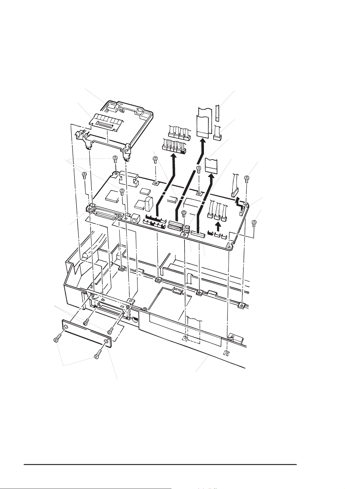
Disassembly and Assembly
4
Type-B I/F Board Guide
Earth Spring for Type-B I/F
CBS Screws (3X8)
Main Board Assembly
CBS Screws
(3X8)
ASF PW Sensor Connector Cable
ASF PL Sensor Connector Cable
CBS Screw (3X8)
CN8
CBS Screw (3X8)
CN15
CBS Screw (3X8)
CP Screws (3X6)
CBS Screws (3X8)
CN11
CN17
Lower Housing
Upper Connector Cover
Figure 3-10. C203 MAIN board Removal
3-1
Rev. A
Page 84

EPSON Stylus COLOR 3000
5
3.2.9 Main Waste Ink Drain Pad Removal
Note) In case the value for the protect counter A* has reached the limit and the maintenance error is
indicated, or the value has exceeded 60,000, replace the waste ink drain pads on the agreement
with your customer.
*: The value for the protect counter A can be found on the sheet printed during the default setting
mode.
(Refer to Chapter 1, Section 1.5.2.1.)
1. Perform EEPROM reset. (See Section 1.5.1 in Chapter 1.)
2. Remove upper housing. (See section 3.2.1.)
3. Remove the printer mechanism unit. (See Section 3.2.6.)
4. Remove the main waste ink drain pads. (See Section 3.2.9.)
WORK POINT
Current value for the protect counter A is shown along with the RO M version number on t he
test print sheet (1st line on the t op page) printed in the default setting mode. (See Section
1.5.2.)
Cartridge Holder Unit
Waste Ink Drain Pad
Lower Housing
Figure 3-11. Main Waste Ink Drain Pad Removal
Rev. A
3-1
Page 85

Disassembly and Assembly
6
3.2.10 PL (Paper Length) Sensor Removal
1. Remove the upper housing. (See section 3.2.1.)
2. Remove the printer mechanism unit. (See Section 3.2.6.)
3. Disconnect the connector cable for the PL sensor from the CN11 on the main board assembly.
4. Using tweezers, release 3 hooks securing the PL sensors to the lower housing.
WORK POINT
Make sure you connect each connector cable to the appropr iate connector paying attention
to the cable length which locates the proper connect or.
Connector Switches
Figure 3-12. PL Sensor Removal
Lower Housing
3-1
Rev. A
Page 86

EPSON Stylus COLOR 3000
7
3.2.11 Printer Mechanism Disassembly
Section 3.2.11.1 thorough to Section 3.2.11.18 describe procedures for printer mechanism unit
disassembly.
3.2.11.1 CR Motor Removal
1. Remove the printer mechanism unit. (See Section 3.2.6.)
2. Dismount the belt tension spring to loosen the timing belt.
3. Remove the timing belt from the pulley on the CR motor.
4. Release the joint f or the CR m otor and base fr ame ass embly by turning the motor countercloc kwise in
the order shown by the steps 1 to 3 in Figure 3-13. Then remove the CR m otor by pulling it toward the
bottom edge of the base frame assembly.
CR Motor
CR Motor Pulley
Base Frame Assembly
Belt Tension Spring
Timing Belt
Figure 3-13. CR Motor Removal
CAUTION
CR motor fan and CR motor assembly are 2 separ ate par ts. Theref ore be sur e to mount t he
CR motor fan with specified adhesive when replacing the CR motor. Make sure that you
leave some portion of 0 to 2 mm on the end of the CR motor shaft, as shown in Figure 3-14.
CR Motor Assembly
Shaft End :0~2 mm
Adhesion
Indent side facing outward
CR Motor Fan
Figure 3-14. Adhering the CR Motor Fan to the CR Motor
Rev. A
3-1
Page 87

Disassembly and Assembly
8
3.2.11.2 Pump Motor Assembly Removal
1. Remove the printer mechanism unit. (See Section 3.2.6.)
2. Remove the connector cable for the pump motor assembly securing the pump motor to the printer
mechanism unit from the clump.
3. Rem ove 2 screws (CBS, 3x6) securing the pump m otor assembly to the sub frame as sembly. Then
remove the pump motor assembly.
CBS Screws (3X6)
Pump Motor Assembly
Sub Frame Assembly
Figure 3-15. Pump Motor Assembly Removal
3-1
Rev. A
Page 88

EPSON Stylus COLOR 3000
9
3.2.11.3 PF Motor Assembly Removal
1. Remove the printer mechanism unit. (See Section 3.2.6.)
2. Remove the connector cable for the PF motor assembly from the clump attached to the printer
mechanism unit.
3. Rem ove 2 screws (CBS, 3x6) securing the PF motor assem bly to the left fram e unit. Then rem ove the
PF motor assembly.
WORK POINT
The PF motor pinion gear is made precise and easy to rust. Therefore, be careful not to
touch it with your bare hands or bump it against other objects.
CBS Screws (3x6)
PF Motor Assembly
Left Frame Unit
Figure 3-16. PR Motor Assembly Removal
Rev. A
3-1
Page 89

Disassembly and Assembly
0
3.2.11.4 Front/Rear PE Sensor Removal
1. Remove the printer mechanism unit. (See Section 3.2.6.)
2. Using tweezers, release 2 hooks securing the front and rear PE sensors to the rear paper guide
assembly at the bottom of the printer mechanism unit. Then remove the sensors.
3. Disconnect the sensor connector cables from the sensor connectors.
Rear Paper Guide Assembly
Connector Cable for the Rear PE Sensor
Rear PE Sensor
Connector Cable for the Front PE Sensor
Figure 3-17. Front/Rear PE Sensor Removal
Hooks
Front PE Sensor
3-2
Rev. A
Page 90
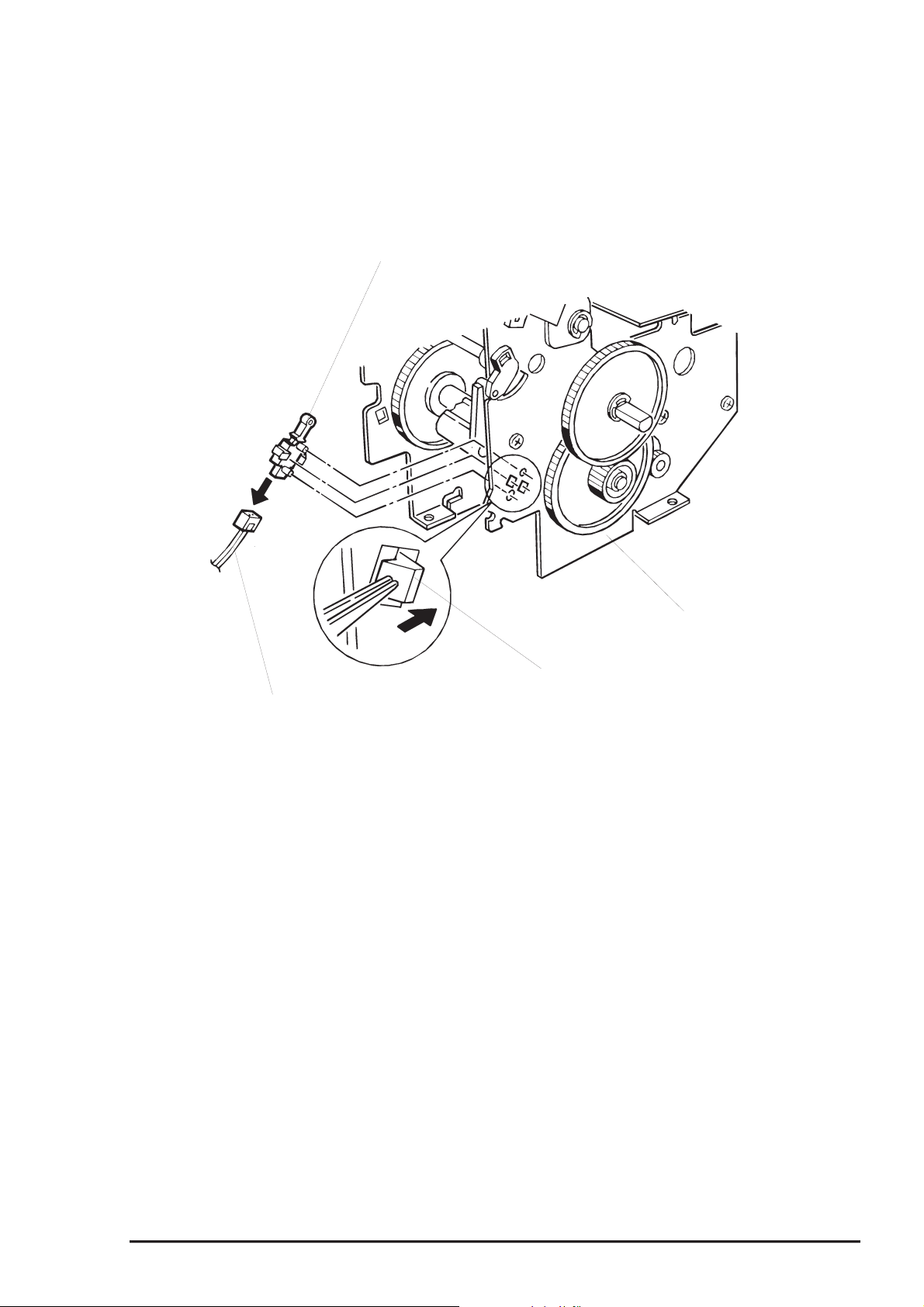
EPSON Stylus COLOR 3000
3.2.11.5 Release Sensor Removal
1. Remove the printer mechanism unit. (See Section 3.2.6.)
2. Using tweezers, releas e 1 hook securing the release sensor to the left fr ame unit. Then rem ove the
release sensor.
Release Sensor
Release Sensor Connector Cable
Figure 3-18. Release Sensor Removal
Left Frame Unit
Hook
Rev. A
3-21
Page 91

Disassembly and Assembly
2
3.2.11.6 Paper Eject Frame Unit Removal
1. Remove the printer mechanism unit. (See Section 3.2.6.)
2. Remove connector cables for the HP sensor and cover open sensor from the connectors on the
sensors.
3. Remove 4 screws (CBS, 3X6) securing the paper eject frame unit to the printer mechanism unit.
4. Remove the paper eject fram e unit from the printer m echanism unit by releasing the joint with the CR
unit.
WORK POINT
When removing the paper eject frame unit, insert a piece of clean paper or equivalent
between the platen surface in the paper eject frame unit and printheads in the CR unit to
protect the printheads.
CBS Screws (3X6)
Paper Ejecft Frame Unit
CBS Screws (3X6)
Printer Mechanism Unit
Figure 3-19. Paper Eject Frame Unit
3-2
Rev. A
Page 92

EPSON Stylus COLOR 3000
3
3.2.11.7 Pump Unit Removal
1. Remove the printer mechanism unit. (See Section 3.2.6.)
2. Remove the paper eject frame unit. (See Section 3.2.11.6.)
3. Remove 2 screws (1 CBS, 3X6 and 1 CBP, 3X 8) s ec uring the pump unit to the printer mechanis m unit.
Then remove the pump unit.
Head Cleaner
CBS Screws (3X6)
Pump Unit
Head Cleaner Lever
(See Secction 3.2.11.14, Step 6.)
Draining Pipe
ASF Transmission Frame Unit
Sub Waste Ink Drain Pad
Right Main Frame
CBP Screw (3X8)
Figure 3-20. Pump Unit Installation
WORK POINT
When installing the head cleaner to the pump unit , f ace the rubber part of the clear t o t he
pump side, as shown in Figure 3-20.
When installing the pump unit, place the tubes into the cutout fir st and t hen insert t he sub
waste ink pads to set the tubes between them.
Rev. A
3-2
Page 93

Disassembly and Assembly
4
3.2.11.8 Edge Guide Unit Removal
1. Remove the printer mechanism unit. (See Section 3.2.6.)
2. Release the joints for the slide covers on the LD shaft and the edge guides.
3. Disconnect the connector cable for the PQ (Paper Q uantity) sensor loc ated at the r ight s ide of the r ight
edge guide.
4. Remove 1 screw (CBS, 3X8) securing the ink cartridge holder to the m iddle frame so that the flange
nut under the cartridge holder will be removed easily in the next step.
5. Rem ove 2 flange nuts (M4) sec uring the edge guide unit to the left fr ame as sembly and m iddle fram e
unit. Then remove the edge guide unit.
Flange Nut
LD Shaft
Slide Covers
CBS Screw (3X8)
Cartridge Holder Unit
Flange Nut
Rotary Damper
Edge Guide Unit
Figure 3-21. Edge Guide Unit Removal
WORK POINT
When installing the edge guide unit to the printer mechanism unit, engage the rack on the
edge guide unit with the pinion on the damper.
3-2
Rev. A
Page 94

EPSON Stylus COLOR 3000
5
WORK POINT
When installing the edge guide unit to the print er m echanism unit, engage the edge guide
unit with the main bottom frame, as shown in Figure 3-22.
Be sure to fix the flange nuts with the specif ied adhesive. ( See Chapt er 6.)
Bottom Main Frame
Spring
Rear
Edge Guide Unit
Front
Figure 3-22.
Joining the Edge Guide Frame and Bottom Main Frame
Rev. A
3-2
Page 95

Disassembly and Assembly
6
3.2.11.9 PQ (Paper Quantity) Sensor Board Assembly Removal
1. Remove the printer mechanism unit. (See Section 3.2.6.)
2. Remove the edge guide unit. (See Section 3.2.11.8.)
3. Remove 2 pan camera screws (2X5.5) securing the PQ sensor cover to the edge guide unit.
4. Remove 1 tension spring securing the PQ sensor sub lever to the PQ sensor, and remove the PQ
sensor sub lever.
5. Remove 1 pan cam era 1B tight screw (2X3.5) securing the PQ sensor to the right edge guide. Then
remove the PQ sensor board assembly.
CAUTION
Do not apply too much torque when tightening the screws. Otherwise, the threads of the
tapped holes in the edge guide unit might crush.
PQ Sensor Lever Assembly
PQ Sensor Board Assembly
Right Edge Guide
Tension Spring (0.84)
PQ Sensor Sub Lever
PQ Sensor Cover
Pan Camera Screw
1 (2X5.5)
Pan Camera 1B Tight Screw (2X3.5)
Figure 3-23. PQ Sensor Removal
3-2
Rev. A
Page 96

EPSON Stylus COLOR 3000
7
3.2.11.10 ASF PW (Paper Width) Sensor Removal
1. Remove the printer mechanism unit. (See Section 3.2.6.)
2. Remove the edge guide unit. (See Section 3.2.11.8.)
3. Using a screwdriver or other pointing tool, release 1 hook securing the ASF PW sensor cover to the left
edge guide unit. Then remove the PW sensor cover by opening it in 2 steps shown in Figure 3-24.
4. Remove the ASF PW sensor.
WORK POINT
After placing the printer mechanism unit back on the lower housing, connect the PW
sensor connector cable to the PW sensor f irs t . Then attach the ASF PW sensor cover.
When mounting the PW sensor, fit the actuator of the PW sensor into the groove on the
PW sensor sliding plate.
ASF PW Sensor Cover
ASF PW Sensor Board Assembly
ASF PW Sensor Connector Cable
Left Edge Guide
Groove on the Sliding Plate
Figure 3-24. PW Sensor Removal
Rev. A
3-2
Page 97

Disassembly and Assembly
8
3.2.11.11 Ink Cartridge Holder Unit Removal
1. Remove the printer mechanism unit. (See Section 3.2.6.)
2. Remove the paper eject frame unit. (See Section 3.2.11.6.)
3. Remove the pump unit. (See Section 3.2.11.7.)
4. Release 4 coupling screws (M6) connecting each ink tube unit to the corresponding ink cartridge
holder unit, then disconnect the tubes.
5. Remove 4 screws (CBS, 3x6) securing the ink cartridge sub plate to the ink cartridge holder units.
Then remove the sub plate.
6. Rem ove following screws securing the ink cartridge holder units to the ink car tridge fixing plate, and
remove the ink cartridge holder units. (See CAUTION below.)
2 screws (CBP, 3X8) from each of the black, magenta and yellow cartridge holders
3 screws (2 CBP screws ,3x8 and 1 CBS screw, 3X6) from cyan ink cartridge holder
CAUTION
When removing one of the cartridge holders, you need to remove all cartr idge holders on
its right, since they are laid on top of the lef t in the order of yellow magenta cyan and
black from left. For instance, you must remove the black, cyan and magenta ink cartridge
holders to remove the yellow ink cartridge holder.
Be careful when tightening the coupling screw, since the threads in the cartridge is
breakable.
WORK POINT
Note that the coupling screw compresses t he tube fixing O-ring to prevent ink leakage.
Therefore, be sure to install them in the appropriate order, as follows:
1) Insert t he tube to the coupling screw.
2) Insert t he tube to the O-ring.
When installing the ink cartridge holders, f it each ink car tridge holder to the supporting
point of the cartridge holder on its left .
ASP ink cartridge holder assembly has a protection tube, which must be removed once
the ASP ink cartridge is installed.
3-2
Rev. A
Page 98
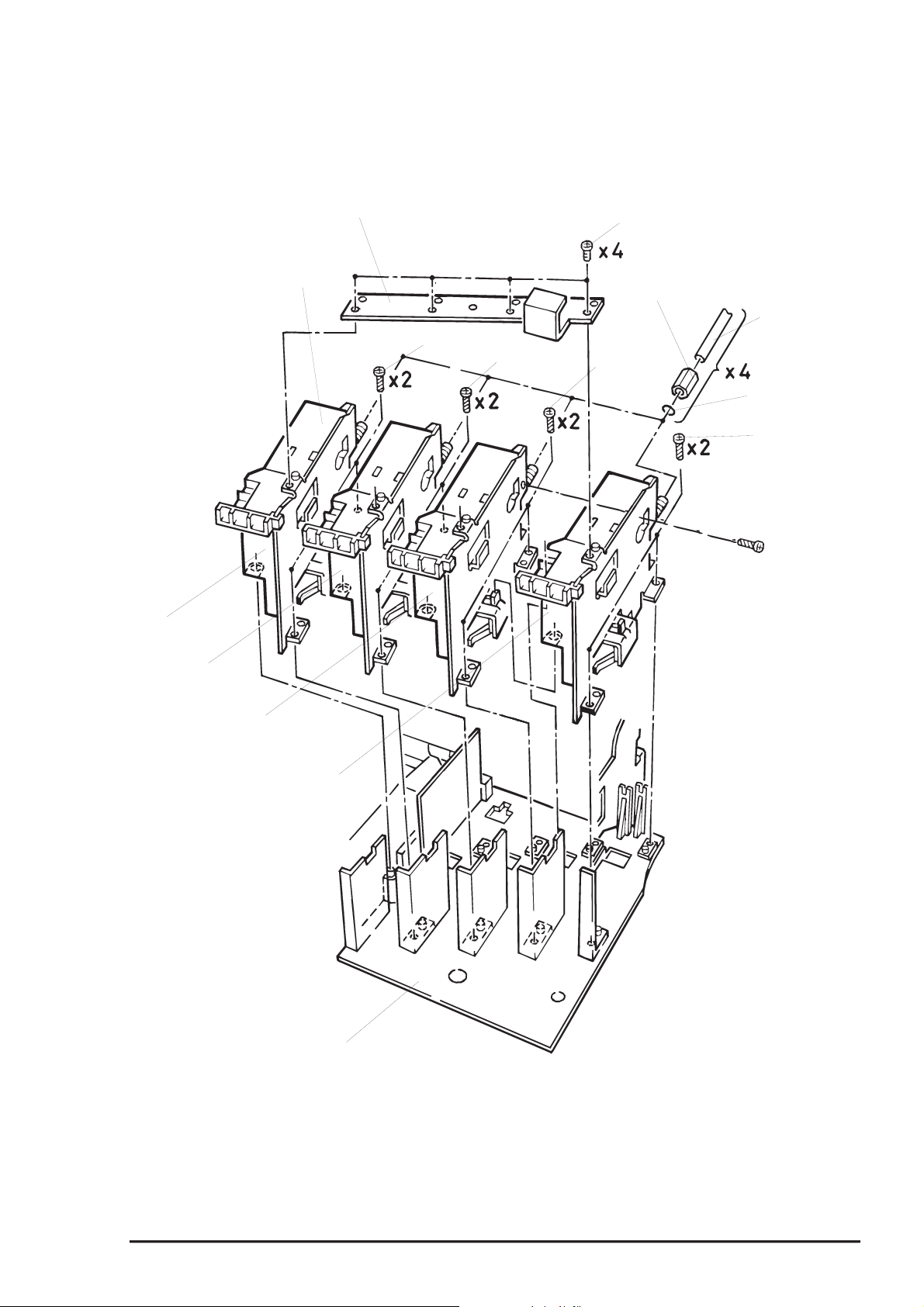
EPSON Stylus COLOR 3000
9
Yellow
Ink Cartridge Supporting Plate
Cartridge Holder Unit
CBP (3X8)
CBP (3X8)
CBS Screw (3x6)
Coupling Screw (M6)
Ink Tube Unit
CBP (3X8)
Tube Fixing O-Ring
CBP (3X8)
CBS Screw (3x6)
Magenta
Cyan
Ink Cartridge Fixing Plate
Black
Figure 3-25. Ink Cartridge Holder Removal
Rev. A
3-2
Page 99

Disassembly and Assembly
0
3.2.11.12 Ink Sensor Assembly Removal
1. Remove the printer mechanism unit. (See Section 3.2.6.)
2. Remove the paper eject frame unit. (See Section 3.2.11.6.)
3. Remove the pump unit. (See Section 3.2.11.7.)
4. Remove the ink cartridge holders. (See Section 3.2.11.11.)
5. Remove the ink sensor connector cables from the clump on the ink cartridge holder mounting plate.
6. Remove 1 scr ew (CBS, 3X10) securing the ink sens or assembly to the ink cartridge holder mounting
plate. Then remove the ink sensor assembly.
3.2.11.13 Ink Cartridge Sensor Assembly Removal
1. Remove the printer mechanism unit. (See Section 3.2.6.)
2. Remove the paper eject frame unit. (See Section 3.2.11.6.)
3. Remove the pump unit. (See Section 3.2.11.7.)
4. Remove the ink cartridge sensor connector cables from the clump on the ink cartridge holder .
5. Remove the ink cartridge holder unit. (See Section 3.2.11.11.)
6. Remove 2 scr ews (CB, 3X10) securing the pin holder to the pin holder assembly and 2 hexagon nuts
(M3). Then remove the pin holder.
7. Remove 1 pan camera B tight screw (2X10) securing the ink cartridge sensor assembly to the pin
holder. Then remove the ink cartridge sensor assembly.
Pan Camera B Tight Screw (2X10)
Ink Cartridge Sensor Assembly
Hexagon Nuts (M3)
Pin Holder
Figure 3-26. Ink Sensor /Ink Cartridge Sensor Assembly Removal
Pin Holder Assembly
Ink Cartridge Holder Fixing Plate
CB Screws (3X10)
Ink Sensor Assembly
CBS Screw (3X10)
3-3
Rev. A
Page 100

EPSON Stylus COLOR 3000
3.2.11.14 CR Unit Removal
1. Remove the printer mechanism unit. (See Section 3.2.6.)
2. Disconnect the HP sensor connector cable from the HP sensor.
3. Remove the belt tension spring to loosen the timing belt.
4. Disengage the timing belt from the pulley on the CR motor and the sub pulley.
5. Remove 1 E-ring and 1 plain washer (6X0.7X12) from each end of the CR guide shaft.
6. If the head cleaner lever* is locking the CR unit, push the lever down manually to unlock the CR unit.
* Head cleaner lever: See Figure 3-20.
7. Remove 1 scr ew (CBS, 3X6) and 2 CR mounting shafts s ecuring the black and the color cables with
the head cable guide to the base frame assembly. Then remove the head cable guide and tube
mounting plate, and remove the ink tubes from the printer mechanism.
8. Release the coupling screws connecting the ink tubes to the ink tube unit. Then remove the tubes.
9. Turn the parallelism adjust bushings joining the CR guide s haft to the right and left fram e assemblies
and release the bushings. Then remove the CR unit along with the CR guide shaft.
10. Remove the CR guide shaft from the CR unit.
Parallelism Adjust Bushing
E-ring
Plain Washer (6X0.7X12)
CR Mounting Shafts
CBS Screw (3X6)
Cable Head Guide
CR Guide Shaft
Printer Mechanism Unit
CR Unit
Figure 3-27. CR Unit Removal
Tube Mounting Plate
HP Sensor Holder
PG Adjust Lever
E-ring
Plain Washer (6X0.7X12)
Parallelism Adjust Bushings
Rev. A
3-31
 Loading...