

Page 1
SERVICE MANUAL
Large Format Color Inkjet Printer
EPSON Stylus Pro 11880/11880C
SEIJ07008
Page 2

Notice:
All rights reserved. No part of this manual may be reproduced, stored in a retrieval system, or transmitted in any form or by any means, electronic,
mechanical, photocopying, recording, or otherwise, without the prior written permission of SEIKO EPSON CORPORATION.
The contents of this manual are subject to change without notice.
All effort have been made to ensure the accuracy of the contents of this manual. However, should any errors be detected, SEIKO EPSON would greatly
appreciate being informed of them.
The above not withstanding SEIKO EPSON CORPORATION can assume no responsibility for any errors in this manual or the consequences thereof.
EPSON is a registered trademark of SEIKO EPSON CORPORATION.
General Notice: Other product names used herein are for identification purpose only and may be trademarks or registered trademarks of their
respective owners. EPSON disclaims any and all rights in those marks.
Copyright © 2007 SEIKO EPSON CORPORATION.
Imaging Products CS, PL & Environmental Management
Page 3

PRECAUTIONS
Precautionary notations throughout the text are categorized relative to 1) Personal injury and 2) Damage to equipment.
DANGER Signals a precaution which, if ignored, could result in serious or fatal personal injury. Great caution should be exercised in performing
procedures preceded by DANGER Headings.
WARNING Signals a precaution which, if ignored, could result in damage to equipment.
The precautionary measures itemized below should always be observed when performing repair/maintenance procedures.
DANGER
1. ALWAYS DISCONNECT THE PRODUCT FROM THE POWER SOURCE AND PERIPHERAL DEVICES PERFORMING ANY MAINTENANCE OR
REPAIR PROCEDURES.
2. NO WORK SHOULD BE PERFORMED ON THE UNIT BY PERSONS UNFAMILIAR WITH BASIC SAFETY MEASURES AS DICTATED FOR ALL
ELECTRONICS TECHNICIANS IN THEIR LINE OF WORK.
3. WHEN PERFORMING TESTING AS DICTATED WITHIN THIS MANUAL, DO NOT CONNECT THE UNIT TO A POWER SOURCE UNTIL
INSTRUCTED TO DO SO. WHEN THE POWER SUPPLY CABLE MUST BE CONNECTED, USE EXTREME CAUTION IN WORKING ON POWER
SUPPLY AND OTHER ELECTRONIC COMPONENTS.
4. WHEN DISASSEMBLING OR ASSEMBLING A PRODUCT, MAKE SURE TO WEAR GLOVES TO AVOID INJURY FROM METAL PARTS WITH
SHARP EDGES.
WARNING
1. REPAIRS ON EPSON PRODUCT SHOULD BE PERFORMED ONLY BY AN EPSON CERTIFIED REPAIR TECHNICIAN.
2. MAKE CERTAIN THAT THE SOURCE VOLTAGES IS THE SAME AS THE RATED VOLTAGE, LISTED ON THE SERIAL NUMBER/RATING
PLATE. IF THE EPSON PRODUCT HAS A PRIMARY AC RATING DIFFERENT FROM AVAILABLE POWER SOURCE, DO NOT CONNECT IT TO
THE POWER SOURCE.
3. ALWAYS VERIFY THAT THE EPSON PRODUCT HAS BEEN DISCONNECTED FROM THE POWER SOURCE BEFORE REMOVING OR
REPLACING PRINTED CIRCUIT BOARDS AND/OR INDIVIDUAL CHIPS.
4. IN ORDER TO PROTECT SENSITIVE MICROPROCESSORS AND CIRCUITRY, USE STATIC DISCHARGE EQUIPMENT, SUCH AS ANTI-STATIC
WRIST STRAPS, WHEN ACCESSING INTERNAL COMPONENTS.
5. REPLACE MALFUNCTIONING COMPONENTS ONLY WITH THOSE COMPONENTS BY THE MANUFACTURE; INTRODUCTION OF SECONDSOURCE ICs OR OTHER NON-APPROVED COMPONENTS MAY DAMAGE THE PRODUCT AND VOID ANY APPLICABLE EPSON WARRANTY.
6. WHEN AIR DUSTER IS USED ON THE REPAIR AND THE MAINTENANCE WORK, THE USE OF THE AIR DUSTER PRODUCTS CONTAINING
THE INFLAMMABLE GAS IS PROHIBITED.
Page 4
About This Manual
This manual describes basic functions, theory of electrical and mechanical operations, maintenance and repair procedures of the printer. The instructions and procedures included
herein are intended for the experienced repair technicians, and attention should be given to the precautions on the preceding page.
Manual Configuration
This manual consists of six chapters and Appendix.
CHAPTER 1.PRODUCT DESCRIPTIONS
Provides a general overview and specifications of the product.
CHAPTER 2.OPERATING PRINCIPLES
Describes the theory of electrical and mechanical operations of the
product.
CHAPTER 3.TROUBLESHOOTING
Describes the step-by-step procedures for the troubleshooting.
CHAPTER 4.DISASSEMBLY / ASSEMBLY
Describes the step-by-step procedures for disassembling and assembling
the product.
CHAPTER 5.ADJUSTMENT
Provides Epson-approved methods for adjustment.
CHAPTER 6.MAINTENANCE
Provides preventive maintenance procedures and the lists of Epsonapproved lubricants and adhesives required for servicing the product.
CHAPTER 7.APPENDIX
Provides the following additional information for reference:
• Connectors
• ASP List
• Exploded Diagrams
Symbols Used in this Manual
Various symbols are used throughout this manual either to provide additional
information on a specific topic or to warn of possible danger present during a
procedure or an action. Be aware of all symbols when they are used, and always read
NOTE, CAUTION, or WARNING messages.
Indicates an operating or maintenance procedure, practice or condition
that is necessary to keep the product’s quality.
Indicates an operating or maintenance procedure, practice, or condition
that, if not strictly observed, could result in damage to, or destruction of,
equipment.
May indicate an operating or maintenance procedure, practice or
condition that is necessary to accomplish a task efficiently. It may also
provide additional information that is related to a specific subject, or
comment on the results achieved through a previous action.
Indicates an operating or maintenance procedure, practice or condition
that, if not strictly observed, could result in injury or loss of life.
Indicates that a particular task must be carried out according to a certain
standard after disassembly and before re-assembly, otherwise the quality
of the components in question may be adversely affected.
Page 5

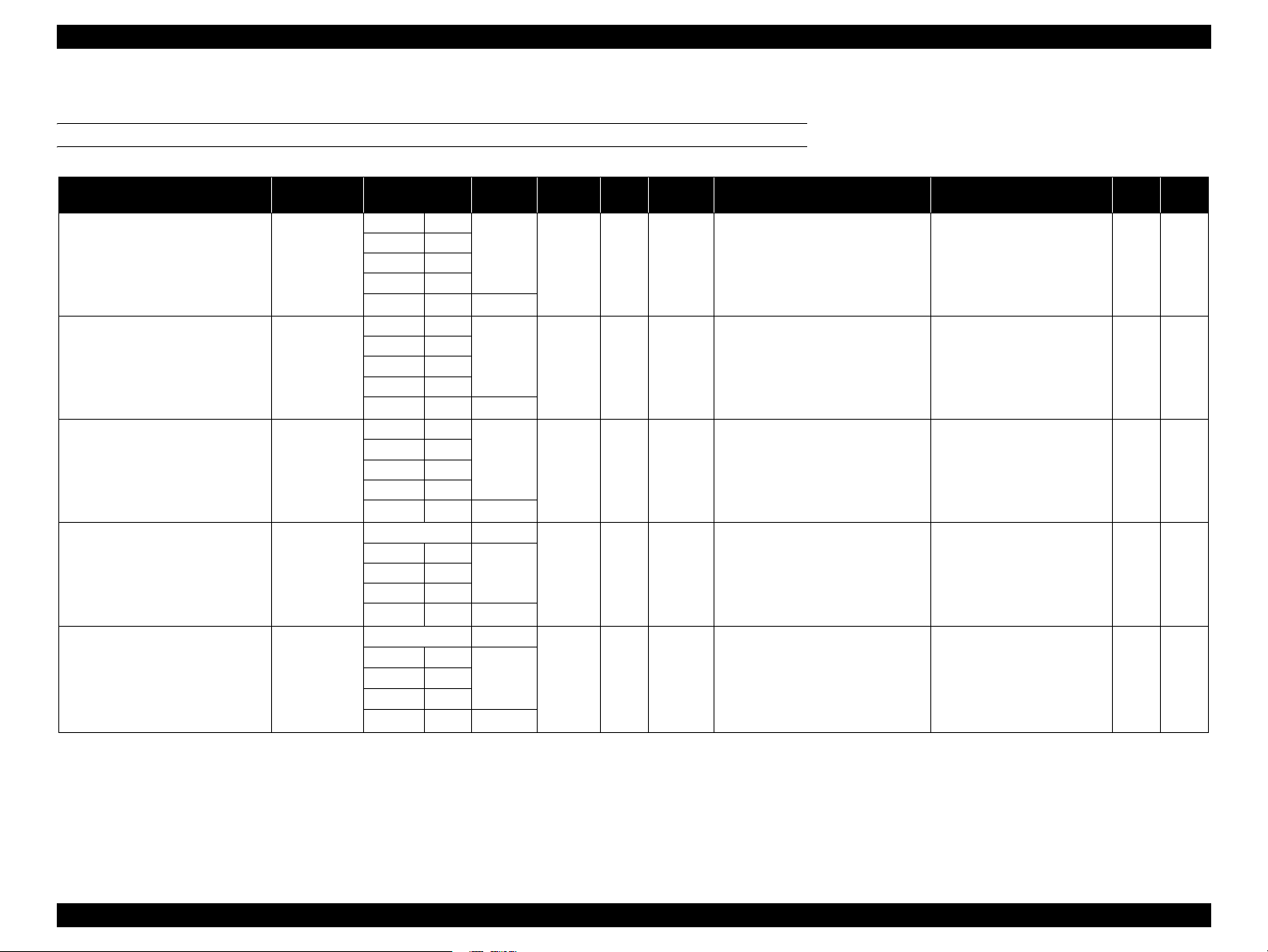
Revision Status
Revision Date of Issue Description
A September 25, 2007 First release
B December 26, 2007 Rivise
<Chapter 1>
• "1.2.4 Reliability/Durability" (P. 14): Ink tube’s life was revised.
• "1-6 Designated Roll Paper List"
<Chapter 2>
• "2.7 Other Mechanisms" (P. 55): Auto nozzle check was deleted.
<Chapter 3>
• "3.2 List of Error Messages" (P. 59): Some items were revised.
• "3.4 Remedies for Maintenance Requests"
• "3.5 Remedies for Service Call Error" (P. 68): Some items were revised.
<Chapter 4>
• "4.3.1.2 Unlocking the Carriage Unit" (P. 84): The procedure was revised.
• "4.3.3.1 Control Panel" (P. 92): The procedure was revised.
• "4.3.3.4 Right Side Cover"
• "4.3.3.5 Left Side Cover"
• "4.3.3.7 Rear Cover" (P. 98): The procedure was revised.
• "4.3.7.1 Printhead"
• "4.3.7.2 Ink System Unit"
(P. 147): The procedure was revised.
(P. 16): Some items were revised.
(P. 67): Some items were revised.
(P. 95): The procedure was revised.
(P. 96): The procedure was revised.
(P. 150): The procedure was revised.
Page 6

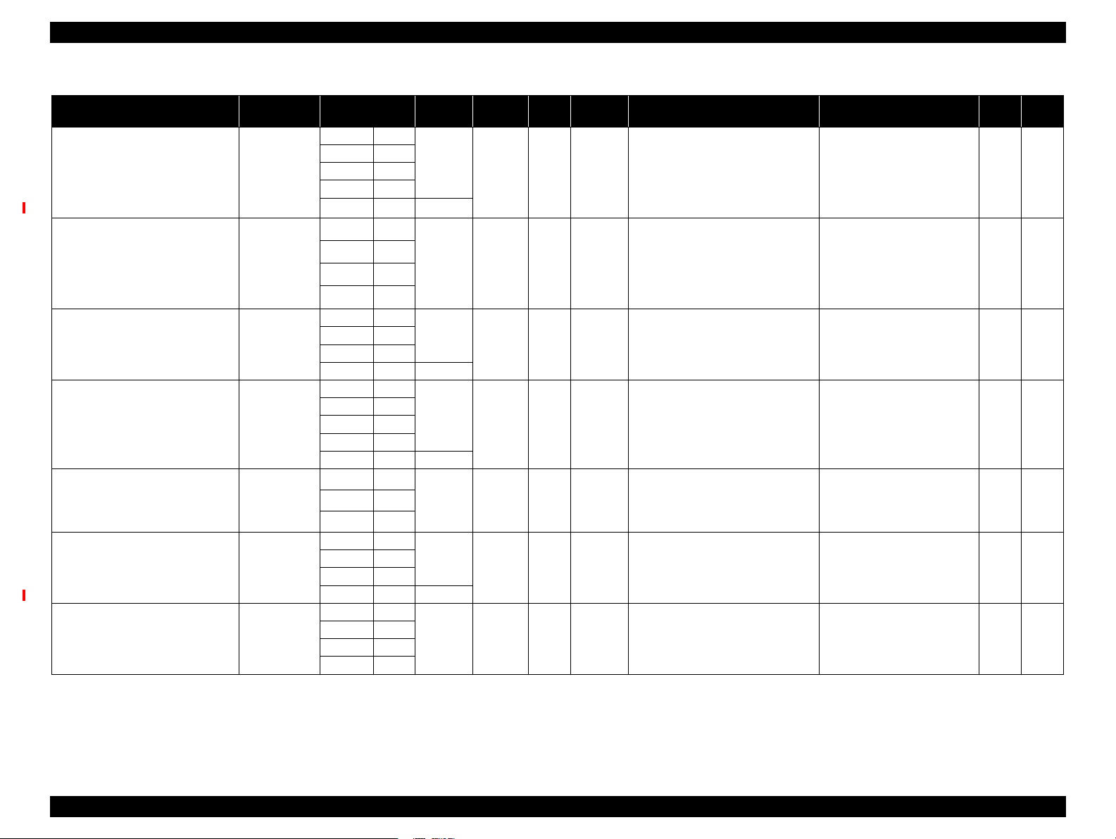
Revision Date of Issue Description
B December 26, 2007 <Chapter 5>
• "5.1.3 Parts and Units that Require Adjustments" (P. 166):
Some items were added.
• "5.1.4 Required Adjustments by Part or Unit"
• "5.1.5 Description of Adjustments"
• "5.2.7 Air Leak Check for Ink Supply System" (P. 180):
• "5.3.2 Head Rank ID"
• "5.3.5 Print Head Slant Adjustment (PF)"
• "5.3.6 Print Head Slant Adjustment (CR)"
• "5.3.18 Colorimetric Calibration (Color ID)" (P. 204): Caution was added.
• "5.3.20 Installing Firmware"
• "5.3.22 Auto Bi-D Adjustment"
• "5.3.23 Auto Uni-D Adjustment" (P. 224) Paper size was modified.
• "5.3.26 AID Inspection PG Adjustment"
• "5.3.27 AID Function Check"
• "5.5 Clear Counters" (P. 236): Some items were added.
(P. 185): Caution was added.
(P. 169): Some items were added.
(P. 221): A step was revised.
(P. 223): Paper size was modified.
(P. 228): A step was revised.
(P. 167):
Some items were modified.
Some steps were revised.
(P. 188): A step was revised.
(P. 190):A step was revised.
(P. 226): A step was revised.
Page 7

Stylus Pro 11880/11880C Revision B
Contents
Chapter 1 PRODUCT DESCRIPTION
1.1 Product Description ............................................................................................ 10
1.2 Basic Specifications ............................................................................................ 12
1.2.1 Basic Specifications ................................................................................... 12
1.2.2 Electric Specifications ............................................................................... 12
1.2.3 Environmental Conditions ......................................................................... 13
1.2.4 Reliability/Durability ................................................................................. 14
1.3 Printing Specifications ........................................................................................ 15
1.3.1 Paper Feed Specifications .......................................................................... 15
1.3.2 Paper Specification .................................................................................... 15
1.3.3 Printable Area ............................................................................................ 20
1.3.4 Borderless Printing Specification .............................................................. 21
1.3.5 Cutting of Roll Paper ................................................................................. 22
1.4 Dimensions and Main Components .................................................................... 23
1.4.1 Dimensions and Weight ............................................................................. 23
1.4.2 Part Names ................................................................................................. 23
1.5 Control Panel ...................................................................................................... 24
1.5.1 Menu Mode Settings .................................................................................. 30
1.5.2 Maintenance Mode .................................................................................... 37
1.5.3 Serviceman Mode ...................................................................................... 38
Chapter 2 OPERATING PRINCIPLES
2.1 Overview ............................................................................................................ 43
2.2 Print Mechanism ................................................................................................. 46
2.3 Ink Supply Mechanism ....................................................................................... 47
2.4 Cleaning Mechanism .......................................................................................... 48
2.5 Carriage Mechanism ........................................................................................... 50
2.5.1 Carriage Movement Mechanism ................................................................ 50
2.5.2 Platen Gap Adjustment Mechanism .......................................................... 51
2.6 Paper Feed Mechanism ....................................................................................... 52
2.7 Other Mechanisms .............................................................................................. 55
2.8 Colorimetric Calibration (Color ID) Overview .................................................. 56
Chapter 3 TROUBLE SHOOTING
3.1 Overview ............................................................................................................ 58
3.1.1 Preliminary Check ..................................................................................... 58
3.1.2 Troubleshooting Procedure ........................................................................ 58
3.2 List of Error Messages ....................................................................................... 59
3.3 Remedies for Error Messages ............................................................................. 61
3.4 Remedies for Maintenance Requests ................................................................. 67
3.5 Remedies for Service Call Error ........................................................................ 68
3.6 Remedies for Print Quality Troubles .................................................................. 73
Chapter 4 DISASSEMBLY & ASSEMBLY
4.1 Overview ............................................................................................................ 76
4.1.1 Precautions ................................................................................................. 76
4.1.2 Orientation Definition ................................................................................ 78
4.1.3 Recommended Tools ................................................................................. 78
4.2 Disassembly Flowchart ...................................................................................... 79
4.3 Disassembly and Assembly Procedure ............................................................... 84
4.3.1 Basic Operations ........................................................................................ 84
4.3.2 Consumables/Accessories ......................................................................... 85
4.3.3 Housing ...................................................................................................... 92
4.3.4 Electric Circuit Components ................................................................... 105
4.3.5 Carriage Mechanism ................................................................................ 120
4.3.6 Paper Feed Mechanism ............................................................................ 137
4.3.7 Ink System Mechanism ........................................................................... 147
7
Page 8

Stylus Pro 11880/11880C Revision B
Chapter 5 ADJUSTMENT
5.1 Overview .......................................................................................................... 166
5.1.1 Precautions ............................................................................................... 166
5.1.2 Adjustment Workflow ............................................................................. 166
5.1.3 Parts and Units that Require Adjustments ............................................... 166
5.1.4 Required Adjustments by Part or Unit ..................................................... 167
5.1.5 Description of Adjustments ..................................................................... 169
5.1.6 Tools for Adjustments ............................................................................. 172
5.1.7 Adjustment Program Basic Operations ................................................... 173
5.2 Mechanical Adjustment .................................................................................... 174
5.2.1 CR Timing Belt Tension Adjustment ...................................................... 174
5.2.2 PF Timing Belt Tension Adjustment ....................................................... 175
5.2.3 CR Encoder Sensor Adjustment .............................................................. 176
5.2.4 Ink Mark Sensor Height Adjustment ....................................................... 177
5.2.5 Cutter Height/Position Adjustment .......................................................... 178
5.2.6 PF Encoder Sensor Adjustment ............................................................... 179
5.2.7 Air Leak Check for Ink Supply System ................................................... 180
5.2.8 Paper Cutting Position Check .................................................................. 183
5.3 Basic Adjustment .............................................................................................. 184
5.3.1 RTC&USB ID ......................................................................................... 184
5.3.2 Head Rank ID .......................................................................................... 185
5.3.3 T&B&S (Roll Paper) + Band Feed .......................................................... 186
5.3.4 Cutter Pressure Adjustment ..................................................................... 187
5.3.5 Print Head Slant Adjustment (PF) ........................................................... 188
5.3.6 Print Head Slant Adjustment (CR) .......................................................... 190
5.3.7 Skew Check ............................................................................................. 192
5.3.8 Platen Position Adjustment ...................................................................... 193
5.3.9 Initial Ink Charge Flag ON/OFF .............................................................. 194
5.3.10 NVRAM Backup and Write .................................................................. 195
5.3.11 Ink Discharge ......................................................................................... 196
5.3.12 Initial Ink Charge ................................................................................... 196
5.3.13 Cleaning ................................................................................................. 197
5.3.14 Paper Thickness Sensor Position Adjustment ....................................... 198
5.3.15 PG Adjustment ....................................................................................... 200
5.3.16 Rear Sensor Adjustment ........................................................................ 202
5.3.17 Input Serial Number .............................................................................. 203
5.3.18 Colorimetric Calibration (Color ID) ...................................................... 204
5.3.19 Head Cleaning ....................................................................................... 220
5.3.20 Installing Firmware ................................................................................ 221
5.3.21 Ink Mark Sensor Adjustment ................................................................. 222
5.3.22 Auto Bi-D Adjustment ........................................................................... 223
5.3.23 Auto Uni-D Adjustment ........................................................................ 224
5.3.24 Super Sonic Cleaning ............................................................................ 225
5.3.25 Network Communication Check ........................................................... 225
5.3.26 AID Inspection PG Adjustment ............................................................. 226
5.3.27 AID Function Check .............................................................................. 228
5.3.28 Rear Sensor Position Adjustment .......................................................... 230
5.3.29 Ink Cover Solenoid Adjustment ............................................................ 231
5.4 Check Results ................................................................................................... 232
5.4.1 Check Nozzle ........................................................................................... 232
5.4.2 Print Image .............................................................................................. 233
5.4.3 Print Adjustment Check Pattern .............................................................. 234
5.4.4 Check Alignment ..................................................................................... 235
5.5 Clear Counters .................................................................................................. 236
Chapter 6 MAINTENANCE
6.1 Overview .......................................................................................................... 238
6.2 Cleaning ............................................................................................................ 240
6.3 Lubrication ....................................................................................................... 241
Chapter 7 APPENDIX
7.1 Block Wiring Diagram ..................................................................................... 244
7.2 Parts List ........................................................................................................... 245
7.3 Exploded Diagram ............................................................................................ 249
8
Page 9

PRODUCT DESCRIPTION
CHAPTER
1
Page 10
Stylus Pro 11880/11880C Revision B
1.1 Product Description
Stylus Pro 11880/11880C is a wide-format color inkjet printer that supports up to 64
inch-wide paper. The main features are;
Supports super large-sized paper
Maximum available paper width: 1625.6 mm (64 inch), up to 64 x 80 inch size
Ink configuration
Installs the following nine ink cartridges and equips with a physical ink channel
for each of the nine colors. The black ink is automatically switched between Photo
and Matte black depending on paper type (printing is made in eight colors).
Table 1-1. Ink Colors
Color Abbreviation
Photo Black PK
Matte Black MK
Cyan C
Vivid Magenta VM
Yellow Y
Light Cyan Lc
Vivid Light Magenta VLm
Light Black LK
Light Light Black LLk
Media handling
Supports a variety of media
Auto take-up reel unit comes as standard
Stores roll paper usage history and updates it automatically by reading a
barcode. This enables automatic detection of remaining amount of the paper.
Equips with auto cutter for roll paper
Borderless print is supported
The latest-type RIP
Supports software RIP made by other companies
Options
The following items are optionally available.
Maintenance Tank
Auto cutter spare blade
Roll paper belt
Paper basket
Dual tension roll feed spindle
Super high print quality
Achieves amazing print quality with eight colors of ink, resolutions up to 2880 x
1440 dpi, and variable dot sizes (minimal 3.7 picoliter)
Lower running cost
Employs super high-capacity (700 ml) independent ink cartridges
Equips with the AID function
Ink suction mechanism for automatic nozzle cleaning is provided for each two
head columns independently. It achieves efficient cleaning with low ink
consumed.
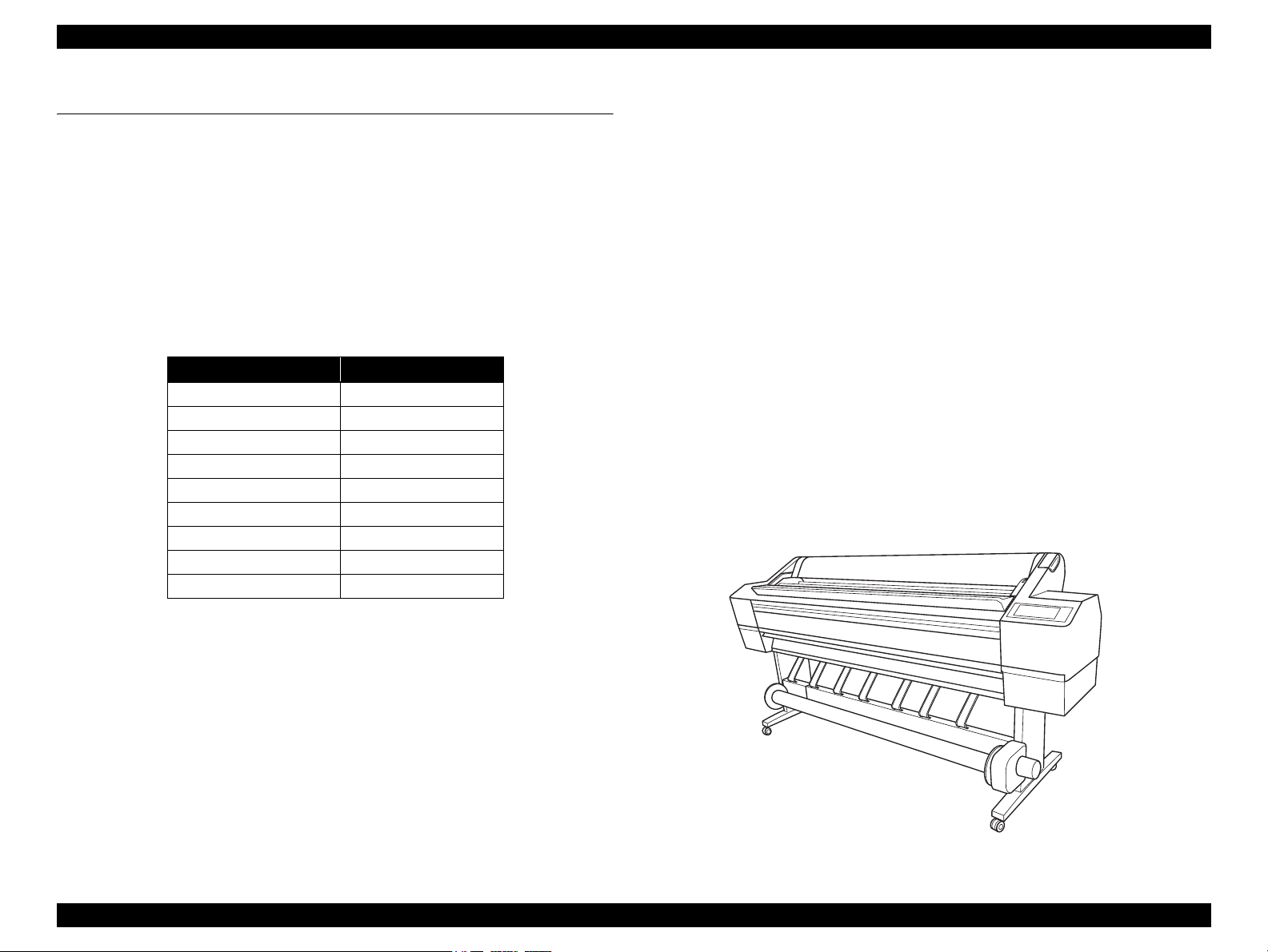
Figure 1-1. External View
PRODUCT DESCRIPTION Product Description 10
Page 11
Stylus Pro 11880/11880C Revision B
High speed printing
Table 1-2. Print Speed (throughput) List
Paper Type Print Quality Dot Size Resolution (dpi) Mode
Draft VSD1 360 x 360 Bi-D MF 300CPS 1 2.0 minutes
Plain paper
Matte paper
FA paper
Coated paper
Speed VSD1 360 x 720 Bi-D MF 300CPS 2 3.3 minutes
Quality VSD2 720 x 720 Bi-D FOL 240CPS 5 6.8 minutes
Fine-720 F. detail on VSD2 720 x 720 Bi-D FOL 240CPS 7 9.0 minutes
Speed VSD1 720 x 360 Bi-D FOL 300CPS 4 2.3 minutes
Quality VSD2 720 x 720 Bi-D FOL 240CPS 8 10.1 minutes
S.Fine-1440 VSD3 1,440 x 720 Bi-D 4-path 240CPS 11 15.3 minutes
S.Photo-2880 VSD4 2,880 x 1,440 Bi-D 4-path 240CPS 18 24.4 minutes
Speed VSD2 720 x 720 Bi-D FOL 240CPS 7 9.0 minutes
Quality VSD3 1,440 x 720 Bi-D 4-path 240CPS 11 15.3 minutes
S.Photo-2880 VSD4 2,880 x 1,440 Bi-D 4-path 240CPS 18 24.4 minutes
Number of
Print Path
Throughput
(A0-size cut sheet print time)
PRODUCT DESCRIPTION Product Description 11
Page 12
EPSON Stylus Pro 11880/11880C Revision A
1.2 Basic Specifications
1.2.1 Basic Specifications
Item Specification
Maximum paper width 1625.6 mm (64 inch)
Print method On-demand inkjet
Printing direction
Printhead Number of nozzles 360 nozzles for each of nine colors
Ink colors
Maximum resolution 2,880dpi x 1,440dpi
Print
speed &
Print area
Alphanumeric
characters
Graphic mode See Table 1-5
Table 1-3. Cartridge Alignment Sequence
Left Ink Holder Right Ink Holder
Row 1 Row 2 Row 3 Row 4 Row 5 Row 6 Row 7 Row 8 Row 9
Vivid
Light
Magenta
(VLm)
Light
Light
Black
(LLK)
Matte
Black
(MK)
Table 1-4. Print speed & Area (alphanumeric characters)
Item Specification
Print speed & Print area
Bi-directional shortest-direction printing (high-speed return,
high-speed skip)
Photo black, Matte black, Cyan, Vivid magenta, Yellow,
Light Cyan, Vivid light magenta, Light black, Light light
black
(See Table 1-3 for the alignment sequence of the cartridges)
See Table 1-4
Light
Black
(LK)
Light
Cyan
(Lc)
Character quality Fine
Character pitch 10 CPI
Print area 643 digits
Print speed Max. 300 cps
Cyan
(C)
Vivid
Magenta
(VM)
Photo
Black
(PK)
Yellow
(Y)
Table 1-5. Print speed & Area (graphic mode)
Horizontal Resolution
(dpi)
360 1633.5 mm (64.31 inch) 23,151 300 cps
720 1633.5 mm (64.31 inch) 46,303 240 cps
1440 1633.5 mm (64.31 inch) 92,606 240 cps
2880 1633.5 mm (64.31 inch) 185,212 240 cps
Note : Includes margins that bleed off the edges of paper. (max. 3 mm for home side, max. 5 mm for the
opposite side)
Max. Print Area Printable Dots
Print
speed
1.2.2 Electric Specifications
Item
Rated voltage 100 to 240 VAC 220 to 240 VAC
Input voltage range 90 to 264 VAC
Rated frequency 50 to 60Hz
Input frequency range 49 to 61Hz
Rated current 1.2A to 0. 6A
Power
consumption
Insulation resistance 10MΩ or more (between AC line and chassis at 500 VDC)
Dielectric strength
Leek current 0.5 mA or less
Compliance with regulations
Note "*1" : The printer goes into the sleep mode when no operation is made for 10 minutes.
Operating 100 W
Sleep mode*
Standby Less than 1W
1
100/120V Model 220/240V Model
1.0 kVrms AC for 1 min. or 1.2 kVrms AC for 1 sec.
(between AC line and chassis)
Conforms to International Energy Star Program
(Category: the harmonic restraint measure guideline)
Conforms to VCCI Class B (with full options installed)
Specification
20 W or lower
PRODUCT DESCRIPTION Basic Specifications 12
Page 13
EPSON Stylus Pro 11880/11880C Revision A
1.2.3 Environmental Conditions
TEMPERATURE/HUMIDITY
Temperature
Operating; 10 to 35
Storage (before unpacking): -20 to 60°C
(within 120 hours under 60 °C, and within 1 month under 40 °C)
Storage (after unpacking): -20 to 40
(within 1 month under 40°C)
Humidity
Operating; 20 to 80% (no condensation)
Storage (before unpacking): -20 to 85% (no condensation)
Storage (after unpacking): 5 to 85% (no condensation)
Humidity (%)
°C
°C
RESISTANCE TO VIBRATION/SHOCK
Status Vibration Shock
Operating 0.15G, 10 to 55Hz 1G, within 1 ms
Storage 0.50G, 10 to 55Hz 2G, within 2 ms
C A U T I O N
Whenever storing the printer, press the Power button to turn
off the power, and make sure that the carriage stops at the right
end to put the cap on the printhead. And even if the printer will
not be used for an extended period, do not remove the ink
cartridges.
Whenever transporting the printer, leave the ink cartridges
installed, and make sure that the printhead is capped. Then
secure the printhead with the metal plate that comes with the
printer being attached to the head.
If you find the carriage is not at the right end position (the
printhead is not capped) while the printer power is off, turn on
the printer and turn it off with the Power button to move the
carriage to the right end. At this time, the ink cartridges must
have been installed.
The print quality is guaranteed under normal room
temperature conditions. If the printer is used under conditions
out of the normal range, color reproduction accuracy may
drop, and bands or smudges may appear on the printout.
Temperature (°C)
Figure 1-2. Temperature/Humidity Range
PRODUCT DESCRIPTION Basic Specifications 13
Page 14
EPSON Stylus Pro 11880/11880C Revision A
1.2.4 Reliability/Durability
Item Specification
Until any one of the following conditions is met.
• Approx. 20,000 pages
Operating life of the printer
Cutter life (reference)
RTC backup
battery
Maintenance unit
Consumables
life
CR motor,
Drive pulley,
Carriage unit,
FFC
Tube 6,300,000 paths
(Super B0 size plain paper, Quality mode, 720x360
FOL Bi-D)
• Carriage life: 6,300,000 paths
• 5 years
64"-wide roll paper, 4 cuts for one page
• Coated paper: approx. 2,000 pages (sheets)
• Film: approx. 1,000 pages (sheets)
5 years or longer
Approx. 20,000 pages (reference value)
(Super B0 size EPSON paper, Draft mode, 720x720,
continuous printing)
Approx. 12,600,000 paths
PRODUCT DESCRIPTION Basic Specifications 14
Page 15
EPSON Stylus Pro 11880/11880C Revision A
1.3 Printing Specifications
1.3.1 Paper Feed Specifications
Item Specification
Paper feed method Friction feed
Line pitch Programmable in units of 1/6 inch or 1,440 inch
Paper feeder
Feed speed 245
1.3.2 Paper Specification
1.3.2.1 Supported Paper
The following explains the supported paper sizes and thickness.
C A U T I O N
Do not use wrinkled, scuffed, torn, or soiled paper.
Load paper just before printing. Do not leave paper loaded on
the printer when not printing. Store paper properly following
the instruction that comes with the paper.
When large quantities of paper need to be prepared in advance,
make a test print using the paper before purchase.
Roll paper manual feed
Cut sheet manual feed
± 10 mm/sec (6.35 mm feed)
PAPER SIZE
Item Specification
Cut sheet
Roll paper
1580
1118
PAPER THICKNESS
Paper width: 210 to 1,118 mm
Paper length: 279 to 1,580 mm
Paper width: 406 to 1,626 mm
Paper length: 127 to 15,000 mm
210
279
15000
406
127
1626
Unit: mm
Item Specification
0.08 to 1.5 mm
Cut sheet
Roll paper 0.08 to 0.5 mm
(Paper length: 279 to 728 mm)
0.08 to 0.5 mm
(Paper length: 728 to 2,032 mm)
PRODUCT DESCRIPTION Printing Specifications 15
Page 16
EPSON Stylus Pro 11880/11880C Revision A
1.3.2.2 Designated Paper
ROLL PAPER
Table 1-6. Designated Roll Paper List
Name
Premium Glossy Photo Paper (250) Photograph,
Premium Semigloss Photo Paper (250) Photograph,
Premium Luster Photo Paper (260) Photograph, 406mm 16" OK! 0.27mm 3" Normal
Premium Glossy Photo Paper (170) Photograph,
Premium Semigloss Photo Paper (170) Photograph,
Note "*1" : OK!: Recommended for borderless printing
OK: Borderless printing is available
NA: Borderless printing is Not available
Borderless printing on the borderless printing available paper (OK) may result in drop in print quality or fail to
produce complete borderless (white margins may appear) due to expanding of the paper. Borderless printing can
be made on commercially available paper, however, note that the availability is restricted by the paper size.
Main
Application
Contact Proof
Contact Proof
Contact Proof
Contact Proof
Size
406mm 16" OK! 0.27mm 3" Normal
610mm 24"
914mm 36"
1118mm 44"
1524mm 60" NA
406mm 16" OK! 0.27mm 3" Normal
610mm 24"
914mm 36"
1118mm 44"
1524mm 60" NA
610mm 24"
914mm 36"
1118mm 44"
1524mm 60" NA
420mm (A2) NA 0.18mm 2" Normal
610mm 24" OK!
914mm 36"
1118mm 44"
1524mm 60" NA
420mm (A2) NA 0.18mm 2" Normal
610mm 24" OK!
914mm 36"
1118mm 44"
1524mm 60" NA
Borderless
*1
Print
Thickness
Core
Diameter
Spindle
Tension
ICC Profile
• Photo Black:
When Bi-D is ON
Pro11880 PGPP250 Bi-D.icc
When Bi-D is OFF
Pro11880 PGPP250 Uni-D.icc
• Matte Black: ---
• Photo Black:
When Bi-D is ON
Pro11880 PSPP250 Bi-D.icc
When Bi-D is OFF
Pro11880 PSPP250 Uni-D.icc
• Matte Black: ---
• Photo Black:
When Bi-D is ON
Pro11880 PLPP260 Bi-D.icc
When Bi-D is OFF
Pro11880 PLPP260 Uni-D.icc
• Matte Black: ---
• Photo Black:
When Bi-D is ON
Pro11880 PGPP170 Bi-D.icc
When Bi-D is OFF
Pro11880 PSPP170 Uni-D.icc
• Matte Black: ---
• Photo Black:
When Bi-D is ON
• Pro11880 PSPP170 Bi-D.icc
• When Bi-D is OFF
Pro11880 PSPP170 Uni-D.icc
• Matte Black: ---
"*2": OK: Auto cut is available
NA: Auto cut is Not available
(manually cut the paper with a commercially available cutter)
Paper Type&Name
indicated by Driver
Photo Paper
Premium Glossy Photo Paper
(250)
Photo Paper
Premium Semigloss Photo Paper
(250)
Photo Paper
Premium Luster Photo Paper
(260)
Photo Paper
Premium Glossy Photo Paper
(170)
Photo Paper
Premium Semigloss Photo Paper
(170)
<Continued to the next page>
Auto
*2
Cut
OK PK
OK PK
OK PK
OK PK
OK PK
Black
Ink
PRODUCT DESCRIPTION Printing Specifications 16
Page 17
Stylus Pro 11880/11880C Revision B
Table 1-6. Designated Roll Paper List
Name
Epson Proofing Paper White
Semimatte
Main
Application
Size
Contact Proof 432mm 17" OK 0.25mm 3" Normal
610mm 24"
914mm 36"
1118mm 44"
1524mm 64" NA
Epson Proofing Paper Publication Contact Proof 432mm 17" OK 0.20mm 3" Normal
610mm 24"
914mm 36"
1118mm 44"
Doubleweight Matte Paper Photograph,
Indoor Signage,
Proof
610mm 24" OK 0.21mm 2" Normal
914mm 36"
1118mm 44"
1626mm 64" NA
Enhanced Matte Paper Photograph,
Indoor Signage,
Proof, Fine Art
Reproduction
432mm 17" OK 0.25mm 3" Normal
610mm 24"
914mm 36"
1118mm 44"
1626mm 64" NA
Watercolor Paper - Radiant White Photograph,
Fine Art
Reproduction
610mm 24" OK 0.29mm 3" High
914mm 36"
1118mm 44"
UltraSmooth Fine Art Paper Photograph,
Fine Art
Reproduction
432mm 17" OK 0.32mm 3" High
610mm 24"
1118mm 44"
1524mm 60" NA
Textured Fine Art Paper Photograph,
Fine Art
Reproduction
432mm 17" OK 0.37mm 3" High
610mm 24"
914mm 36"
1118mm 44"
Note "*1" : OK!: Recommended for borderless printing
OK: Borderless printing is available
NA: Borderless printing is Not available
Borderless printing on the borderless printing available paper (OK) may result in drop in print quality or fail to
produce complete borderless (white margins may appear) due to expanding of the paper. Borderless printing can
be made on commercially available paper, however, note that the availability is restricted by the paper size.
Borderless
*1
Print
Thickness
Core
Diameter
Spindle
Tension
ICC Profile
• Photo Black:
When Bi-D is ON
Pro11880 Proof_WS_Bi-D.icc
When Bi-D is OFF
Pro11880 Proof_WS_Uni-D.icc
• Matte Black: ---
• Photo Black:
When Bi-D is ON
Pro11880 Proof_Pub_Bi-D.icc
When Bi-D is OFF
Pro11880 Proof_Pub_Uni-D.icc
• Matte Black: ---
• Photo Black: ---
• Matte Black:
Pro118800 DWMP.icc
• Photo Black:
Pro11880 EMP_PK.icc
• Matte Black:
Pro118800 EMP_MK.icc
• Photo Black:
Pro11880 WCRW_PK.icc
• Matte Black:
Pro118800 WCRW_MK.icc
• Photo Black:
Pro11880 USFAP_PK.icc
• Matte Black:
Pro118800 USFAP_MK.icc
• Photo Black:
Pro11880 TFAP_PK.icc
• Matte Black:
Pro118800 TFAP_MK.icc
"*2": OK: Auto cut is available
NA: Auto cut is Not available
(manually cut the paper with a commercially available cutter)
Paper Type&Name
indicated by Driver
Proofing Paper
Epson Proofing Paper White
Semimatte
Proofing Paper
Epson Proofing Paper
Publication
Matte Paper
Doubleweight Matte Paper
Matte Paper
Enhanced Matte Paper
Fine Art Paper
Watercolor Paper - Radiant
White
Fine Art Paper
UltraSmooth Fine Art Paper
Fine Art Paper
Textured Fine Art Paper
<Continued to the next page>
Auto
Black
*2
Cut
OK PK
OK MK
OK MK
OK MK
OK PK/
OK PK/
OK PK/
Ink
MK
MK
MK
PRODUCT DESCRIPTION Printing Specifications 17
Page 18
EPSON Stylus Pro 11880/11880C Revision A
Table 1-6. Designated Roll Paper List
Name
Main
Application
Canvas Photograph,
Fine Art
Reproduction
Size
610mm 24" OK 0.46mm 2" Normal
914mm 36"
1118mm 44"
Borderless
*1
Print
Thickness
Core
Diameter
Spindle
Tension
ICC Profile
• Photo Black:
Pro11880 Canvas_PK.icc
• Matte Black:
Pro118800 Canvas_MK.icc
Paper Type&Name
indicated by Driver
Fine Art Paper
Canvas
Auto
Black
*2
Cut
NA PK/
Ink
MK
Note "*1" : OK!: Recommended for borderless printing
OK: Borderless printing is available
NA: Borderless printing is Not available
Borderless printing on the borderless printing available paper (OK) may result in drop in print quality or fail to
produce complete borderless (white margins may appear) due to expanding of the paper. Borderless printing can
be made on commercially available paper, however, note that the availability is restricted by the paper size.
"*2": OK: Auto cut is available
NA: Auto cut is Not available
(manually cut the paper with a commercially available cutter)
PRODUCT DESCRIPTION Printing Specifications 18
Page 19
EPSON Stylus Pro 11880/11880C Revision A
CUT SHEET
Table 1-7. Designated Cut Sheet List
Name Main Application Size
Premium Glossy Photo Paper Photograph, Contact Proof Super A3 OK! 0.27mm
A2 NA
Premium Semigloss Photo Paper Photograph, Contact Proof Super A3 OK! 0.27mm
A2 NA
Premium Luster Photo Paper Photograph Super A3 OK! 0.27mm
A2
Archival Matte Paper Indoor Signage,
Photograph, Proof, Fine
Art Reproduction
Watercolor Paper - Radiant White Photograph, Fine Art
Reproduction
UltraSmooth Fine Art Paper Photograph, Fine Art
Reproduction
Velvet Fine Art Paper Photograph, Fine Art
Reproduction
Textured Fine Art Paper Photograph, Fine Art
Reproduction
Enhanced Matte Posterboard Indoor Signage, Proof,
Fine Art Reproduction
Super A3 OK 0.26mm
A2 NA
Super A3 OK 0.29mm
Super A3 OK 0.46mm
A2 NA
Super A3 OK 0.48mm
A2 NA
24" x 30" OK 0.69mm
36" x 44"
24" x 30" OK 1.3mm
30" x 40" NA
Borderless
*1
Print
Thickness ICC Profile Paper Name indicated by Driver Black Ink
• Photo Black:
When Bi-D is ON
Pro11880 PGPP Bi-D.icc
When Bi-D is OFF
• Pro11880 PGPP_Uni-D.icc
• Matte Black: ---
• Photo Black:
When Bi-D is ON
Pro11880 PSPP Bi-D.icc
When Bi-D is OFF
Pro11880 PSPP Uni-D.icc
• Matte Black: ---
• Photo Black:
When Bi-D is ON
Pro11880 PLPP Bi-D.icc
When Bi-D is OFF
Pro11880 PLPP Uni-D.icc
• Matte Black: ---
• Photo Black: Pro11880 ARMP_PK.icc
• Matte Black: Pro118800 ARMP_MK.icc
• Photo Black: Pro11880 WCRW_PK.icc
• Matte Black: Pro118800 WCRW_MK.icc
• Photo Black: Pro11880 USFAP_PK.icc
• Matte Black: Pro118800 USFAP_MK.icc
• Photo Black: Pro11880 VFAP_PK.icc
• Matte Black: Pro118800 VFAP_MK.icc
• Photo Black: Pro11880 TFAP_PK.icc
• Matte Black: Pro118800 TFAP_MK.icc
• Photo Black: Pro11880 EMPB_PK.icc
• Matte Black: Pro118800 EMPB_MK.icc
Photo Paper
Premium Glossy Photo Paper
Photo Paper
Premium Semigloss Photo Paper
Photo Paper
Premium Luster Photo Paper
Matte Paper
Archival Matte Paper
Fine Art Paper
Watercolor Paper - Radiant White
Fine Art Paper
UltraSmooth Fine Art Paper
Fine Art Paper
Velvet Fine Art Paper
Fine Art Paper
Textured Fine Art Paper
Others
Enhanced Matte Posterboard
PK
PK
PK
PK/MK
PK/MK
PK/MK
PK/MK
PK/MK
PK/MK
Note "*": OK!: Recommended for borderless printing
OK: Borderless printing is available
NA: Borderless printing is Not available
Borderless printing on the borderless printing available paper (OK) may result in drop in print quality or fail to produce complete borderless (white margins may appear) due to expanding of the paper.
Borderless printing can be made on commercially available paper, however, note that the availability is restricted by the paper
size.
PRODUCT DESCRIPTION Printing Specifications 19
Page 20
EPSON Stylus Pro 11880/11880C Revision A
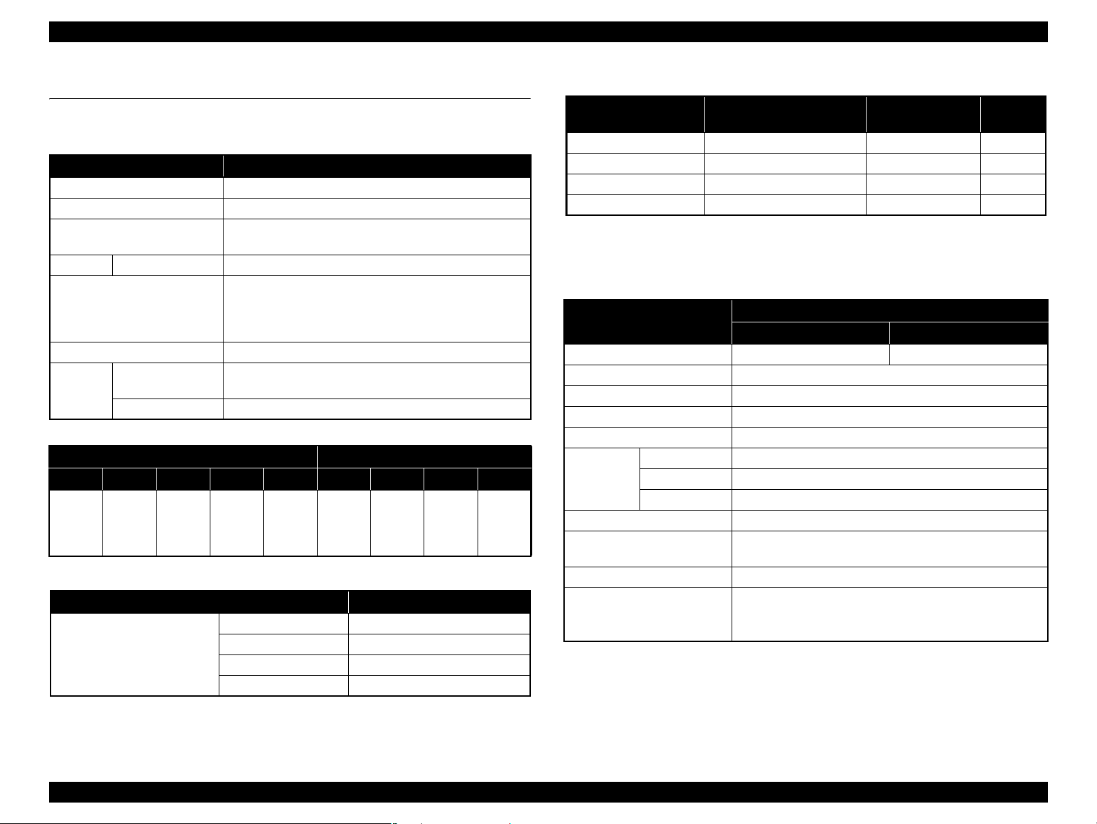
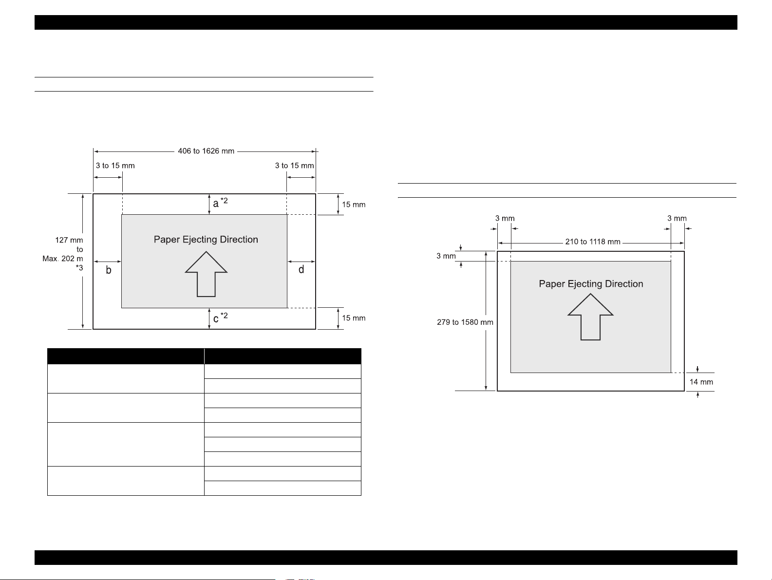
1.3.3 Printable Area
ROLL PAPER
Margins for roll paper depends on the ROLL PAPER MARGIN settings in the
PRINTER SETUP menu.
Note "*1" : When the Default is selected, "a" becomes 20mm and “c” becomes 15mm for the following
paper types; Premium Glossy Photo Paper(250), Premium Semigloss Photo Paper(250), and
Premium Luster Photo Paper(260).
"*2": When the"Roll Paper (Banner)" is selected for the "Source" in the "Paper Settings" of the
printer driver, the top and bottom margins become 0 mm.
"*3": The maximum paper length settable with the printer driver is as follows.
Windows: 15,000 mm (590.6 inch)
Mac OS X: 15,240 mm (600 inch)
When paper length longer than the above is required, select the "Roll Paper (Banner)". The
printer driver allows the setting if the application used for the data supports the length.
CUT SHEET
ROLL PAPER MARGIN settings Explanation
Default
TOP/BOTTOM 15mm
TOP 35/BOTTOM 15MM
3mm
a = c = 15 mm *1
b = d = 3 mm
a = c = 15 mm
b = d = 3 mm
a = 35 mm
c = 15 mm
b = d = 3 mm
a, b, c, d = 3 mm
a, b, c, d = 15 mm
PRODUCT DESCRIPTION Printing Specifications 20
Page 21
EPSON Stylus Pro 11880/11880C Revision A
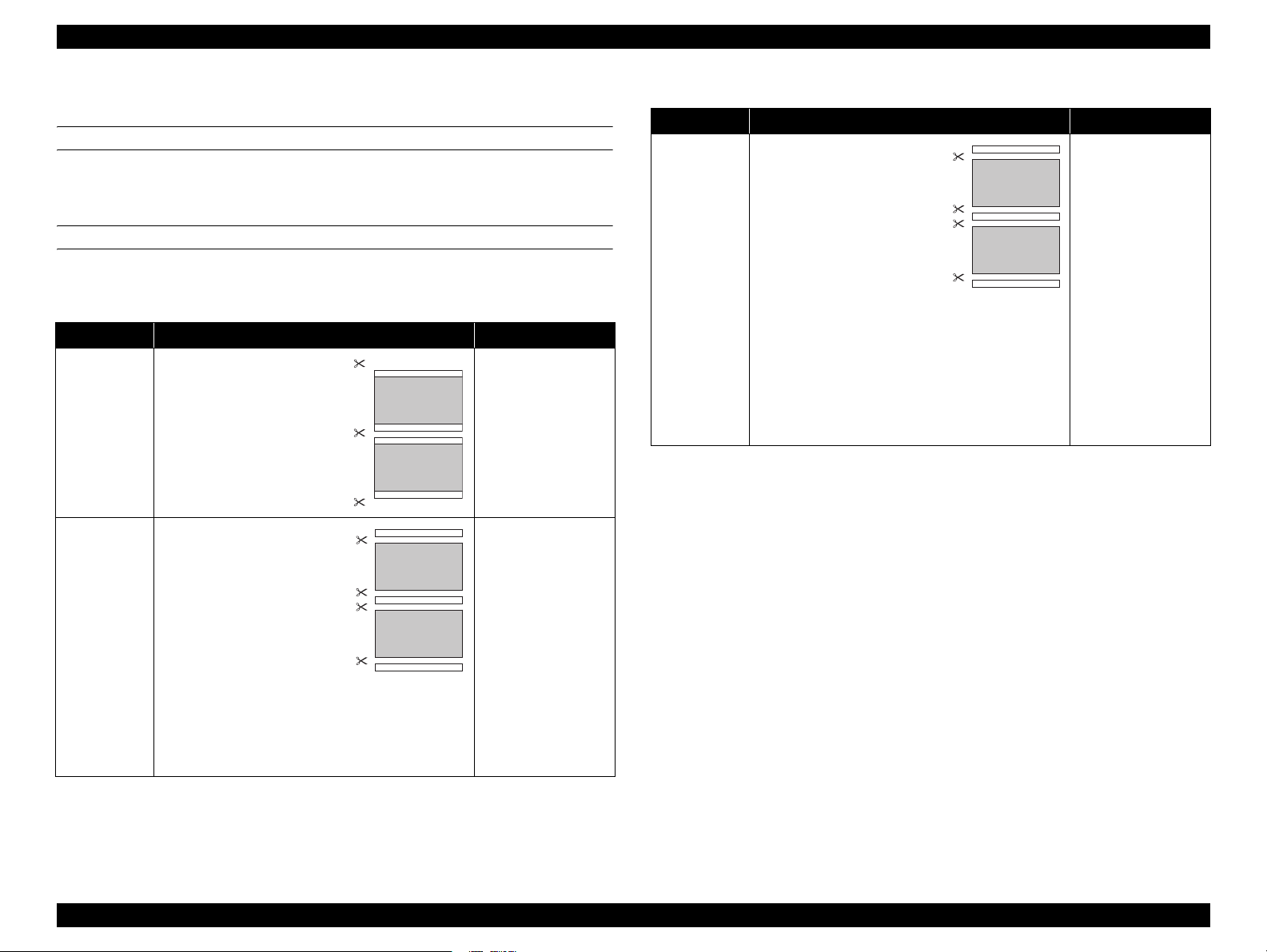
1.3.4 Borderless Printing Specification
AVAILABLE PAPER TYPE
For the paper types and sizes that support the borderless printing, see “1.3.2.2
Designated Paper” on page 16.
BORDERLESS PRINTING MODE
The following types of borderless printing are available with the printer driver.
Table 1-8. Borderless Printing Mode
Driver Setting Printer Operation Remarks
Default
• Printing is interrupted
for cutting off the top
margin of the first
page. This may cause
color inconsistencies
depending on the print
data.
• The cut line between
pages may be slightly
off the border.
Normal Cut*
Single Cut
3
*1*2*
Prints an image bleeding it off
the left and right edges of
paper. The top and bottom
margins are determined by
2
ROLL PAPER MARGIN
setting.
Prints an image bleeding it off
the all edges of paper.
The cutting methods is as
follows.
The minimum width
required for cutting is
applied as the top margin
of the first page, then the
top margin is cut off during
printing.
No margin is provided between pages, and the
cutting is made on the border between the pages.
When the job is finished, the bottom side of the last
page is cut off without margin.
Table 1-8. Borderless Printing Mode
Driver Setting Printer Operation Remarks
Prints an image bleeding it off
the all edges of paper.
The cutting methods is as
follows.
The auto refresh margin is
applied as the top margin
of the first page, then the
Double Cut
3
*1*2*
top margin is cut off during
printing.
The bottom side of each
page is cut off without margin.
The minimum width required for cutting is applied
as margins between pages.
Note "*1" : The cut pages vertical length become about 2mm shorter than the specified size.
"*2": When the Auto Cut is OFF and the Page Line print function is ON, page lines for manual
cutting are printed.
"*3": Color inconsistencies or ink smudges due to the interruption of printing for cutting off top
margins are likely to occur on the following papers.
• Doubleweight Matte Paper
• Singleweight Matte Paper
• Enhanced Matte Paper
• Textured Fine Art Paper
• UltraSmooth Fine Art Paper
• Printing is interrupted
for cutting off the top
margin of the first
page. This may cause
color inconsistencies
depending on the print
data.
• The top and bottom
sides of each page are
cut off at the position
slightly inward the
image edges so that no
white margin appears
on the edges of the cut
pages. This causes the
vertical length of the
cut page about 2mm
shorter than the
specified length.
PRODUCT DESCRIPTION Printing Specifications 21
Page 22
EPSON Stylus Pro 11880/11880C Revision A
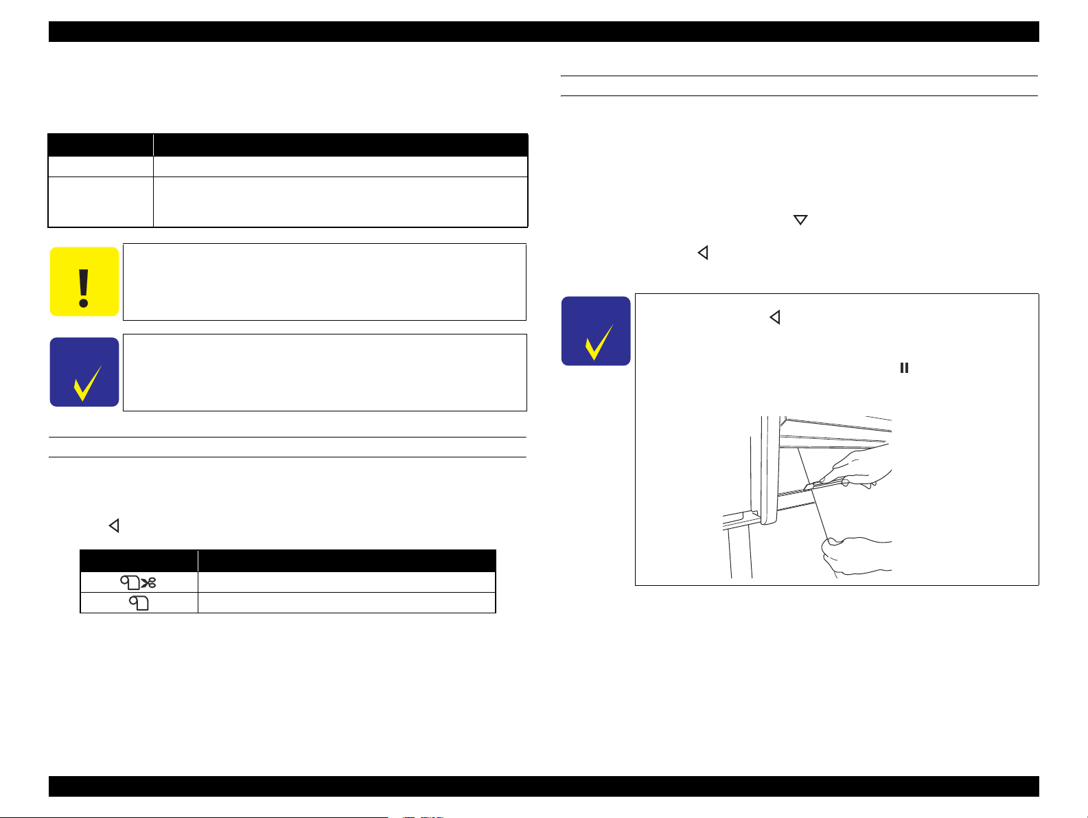
1.3.5 Cutting of Roll Paper
The printer offers both manual and auto cutting for roll paper.
Cut Method Description
Auto cut The printer automatically cuts paper with the built-in cutter.
The user can manually move the built-in cutter to cut paper, or use a
Manual cut
C A U T I O N
C H E C K
P O I N T
SETTING BEFORE PRINTING
The cut method setting can be made by the control panel or the printer driver.
commercially available cutter. Select this setting when using the Auto
Take-up Reel Unit.
Some types of roll paper cannot be cut with the built-in cutter.
Use a commercially available cutter for such types.
It may takes time for the cutting operation. The approx. waiting
time will be indicated on the display of the control panel.
The “Auto Cut” setting of the printer driver takes priority over
the “Roll Auto Cut Off” setting made by the control panel.
HOW TO CUT
Auto cut
The printer automatically cuts paper with the built-in cutter each time a page is
printed.
Manual cut
Follow the procedure below to cut paper at the desired position.
1. After a page is printed, press the button to advance the paper to the cut
position.
2. Hold down the button for 3 seconds or longer.
The built-in cutter moves and cuts the paper.
C H E C K
P O I N T
When the paper type is the one that the built-in cutter does not
support, pressing the button advances the paper to the position
for manual cutting using a commercially available cutter. Cut the
paper manually with your cutter along the lower frame of the front
cover. When cutting is completed, press the button to return the
panel display to the normal standby status.
When setting with the control panel (for printing a status sheet or etc.)
Press button to select the cut method.
Icon Description
Roll Auto Cut On
Roll Auto Cut Off
When setting from a computer
Select “Auto Cut” in the “Paper Setting” window of the printer driver.
PRODUCT DESCRIPTION Printing Specifications 22
Page 23
EPSON Stylus Pro 11880/11880C Revision A
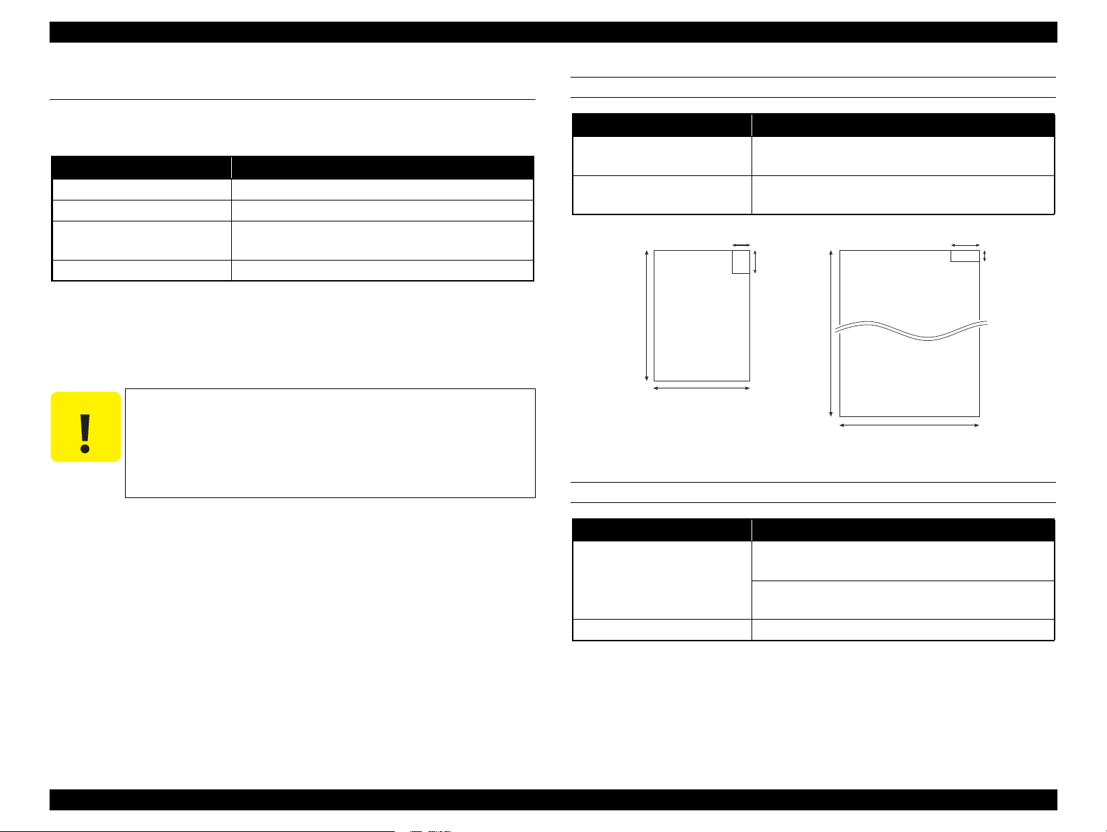
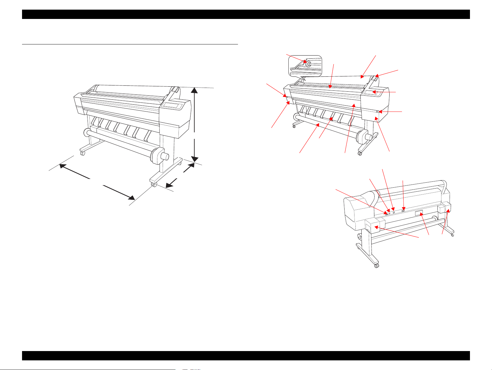
1.4 Dimensions and Main Components
This section provides the printer dimensions and shows the main components.
1.4.1 Dimensions and Weight
1,190 mm
685 mm
2,348 mm
Figure 1-3. Printer Dimensions (standard)
1.4.2 Part Names
Spindle
Ink Cover
Open Button
Ink Cartridge
Compartment
Auto Take-up Reel Unit
Auto Take-up Reel Unit Connector
Paper Eject
Paper Roll
Front Cover
USB Interface Connector
Roll Paper
Paper Lever
Control Panel
Ink Cover Open Button
Ink Cartridge Compartment
Network Interface Connector
AC Inlet
Dimensions
Standard (with the Auto Take-up Reel Unit):
2,348 (W) x 685 (D) x 1,190 (H) mm
Maintenance
Tank
Without the Auto Take-up Reel Unit:
2,348 (W) x 667 (D) x 1,190 (H) mm
When using the Paper Basket:
2,348 (W) x 740 (D) x 1,190 (H) mm
Figure 1-4. Part Names
Weight
Printer main body and the Base Unit (excludes the ink cartridges and paper):
Approx. 150.5 kg
Printer main body only (excludes the ink cartridges and paper):
Approx. 127.3 kg
The Base Unit and the Auto Take-up Reel unit: Approx. 23.2 kg
PRODUCT DESCRIPTION Dimensions and Main Components 23
Page 24
EPSON Stylus Pro 11880/11880C Revision A
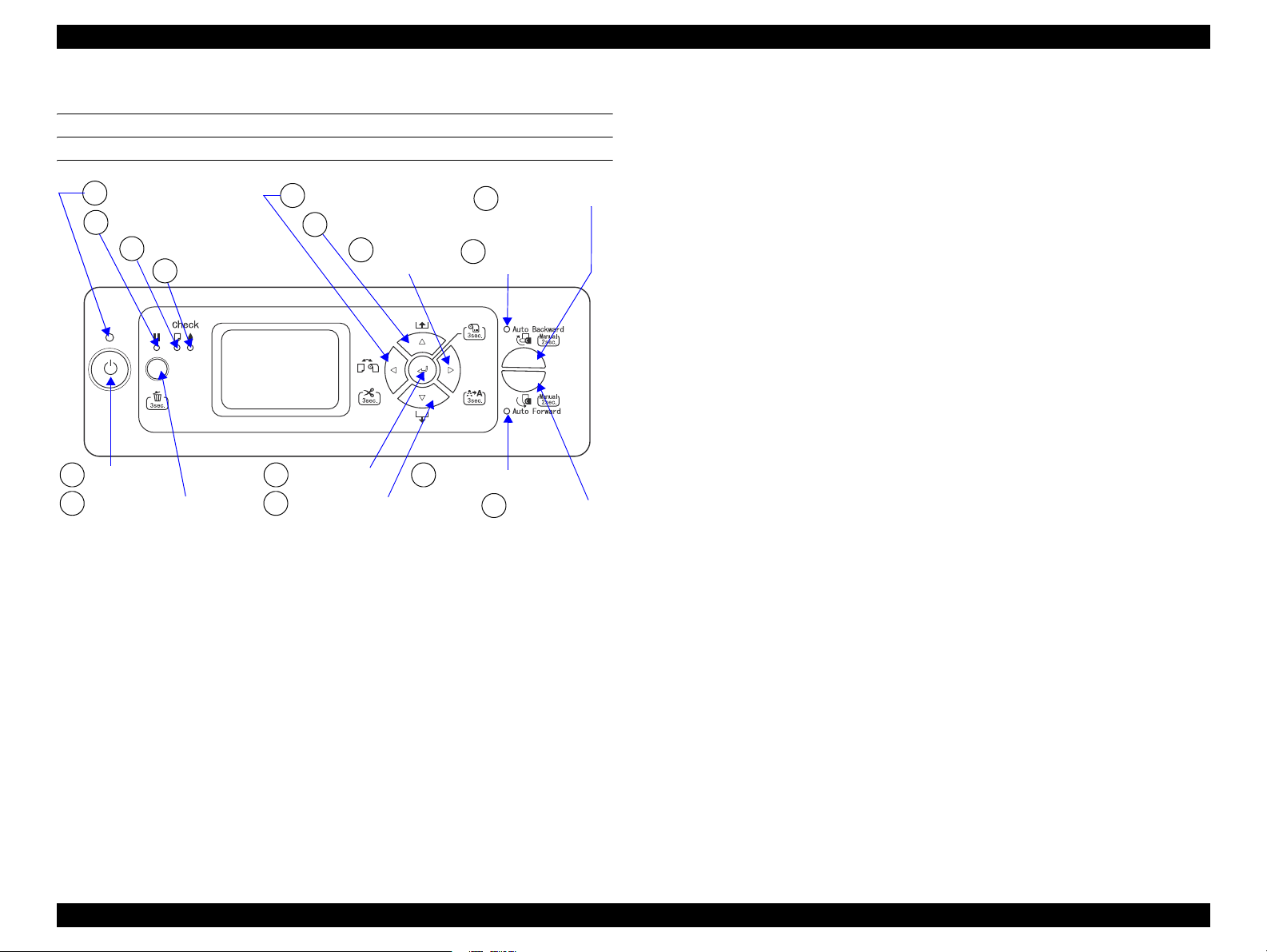
1.5 Control Panel
BUTTONS AND LIGHTS
Power Light
A
Pause Light
B
Paper Check Light
C
Ink Check Light
D
[Paper Source (left)] button
4
[Paper Feed (reverse)] button
5
[Menu (right)]
3
button
[Auto Backward]
9
button
Auto Backward
E
Light
[Power] button
1
[Pause/Reset] button
2 6
[Enter] button
7
[Paper Feed (forward)] button
Auto Forward Light
F
8
[Auto Forward]
button
PRODUCT DESCRIPTION Control Panel 24
Page 25

EPSON Stylus Pro 11880/11880C Revision A
BUTTONS
Button Name
Function
When pressed normally When pressed down for 3 sec. For panel setting
1[Power] Turns the printer On or Off. --- Power-off
2[Pause/Reset]
3 [Menu (right)]
4 [Paper Source (left)]
5 [Paper Feed (reverse)]
6 [Paper Feed (forward)]
7[Enter]
8[Auto Forward]
9 [Auto Backward]
2
+ 4[Pause] + [Paper Source]
• Pauses or resumes the operation.
• Resets the paper settings to the default.
• Makes the printer recover from an error.
• During printing: Goes to the PRINTER STATUS menu.
• When not printing: Goes to Menu mode.
• During printing: Does not function.
• When not printing:
Changes the paper type.
When the ROLL PAPER REMAINING function is set to ON, switching
between roll paper and cut sheet cannot be made.
• When roll paper is loaded: Feeds the paper backward.
• When roll paper is not loaded: Does not function.
• While the Paper Lever is released: Increases the power of the paper suction
fan.
• When roll paper is loaded: Feeds the paper forward.
• When roll paper is not loaded: Does not function.
• While the Paper Lever is released: Decreases the paper suction fan power.
• When cut sheet is selected and a cut sheet is loaded on the printer: Feeds the
cut sheet to the print start position.
• When a cut sheet has been set in the printer: Ejects the cut sheet.
• When printing on a cut sheet is finished and the next paper has not been set:
Ejects the cut sheet.
• Other than the above: Does not function.
• Automatically reels roll paper with the printed surface facing outward when the roll paper is detected by the sensor.
• When pressed for two seconds during the Auto Forward light is on, reeling operation by the Auto Take-up Reel Unit and paper feeding operation by the printer are made
simultaneously.When pressed for two seconds during the light is off, only the Auto Take-up Reel Unit operates to reel the paper.
• Automatically reels roll paper with the printed surface facing inward when the roll paper is detected by the sensor.
• When pressed for two seconds during the Auto Backward light is on, reeling operation by the Auto Take-up Reel Unit and paper f
simultaneously.When pressed for two seconds during the light is off, only the Auto Take-up Reel Unit operates to reel the paper.
Cancels or activates the ROLL PAPER REMAINING function while the printer
is in standby mode.
Cancels the print job.
(when D4 is not set: reset)
• When less than 0.8 mm paper thickness is detected by the sensor: Runs a head
cleaning.
• When more than 0.8 mm paper thickness is detected by the sensor: Makes the
printer recover from a cleaning error, and runs a head cleaning.
• When printing on paper whose thickness is detected as more than 0.8 mm: Does
not function.
• When paper exists (not during printing and not error status):
When Auto Roll Paper Cut is ON: Cuts and ejects the paper.
When Auto Roll Paper Cut is OFF: Advances the paper to the manual cut position.
Cut sheet: Ejects the sheet.
• When drying ink: Cancels the operation and ejects the paper.
• Other than the above: Does not function.
• When roll paper is loaded: Feeds the paper backward at high speed.
• When roll paper is not loaded: Does not function.
• When roll paper is loaded: Feeds the roll paper forward at high speed.
• When roll paper is not loaded: Does not function.
• When the ROLL PAPER REMAINING - REMAINING PPR SETUP is set to
ON: PRINT EVERY PAGE, and paper type setting is roll paper:
Prints a barcode on the top edge of the roll paper and releases the Paper Lever.
eeding operation by the printer are made
--- ---
Cancels the panel
settings.
Goes to the next
item.
Goes to the
previous item.
Increases the set
value.
Decreases the set
value.
Accepts the change,
Executes the
operation, Stores
the settings
PRODUCT DESCRIPTION Control Panel 25
Page 26
EPSON Stylus Pro 11880/11880C Revision A
LIGHTS (LED)
Name Color Status Description
ON The printer power is on.
A
Power Green
B
Pause Yellow
C
Paper Check Red
D
Ink Check Red
E
AutoForward Green
F
AutoBackward Green
Flashing*1
OFF The printer power is off.
ON
OFF The printer is in the standby mode.
ON Paper is not ready for printing.
Flashing
OFF No error or warning is occurring.
ON An error related to ink is occurring.
Flashing*1 A warning related to ink is occurring.
OFF No error or warning is occurring.
ON The AutoForward function is enabled.
Flashing
OFF The AutoForward function is disabled.
ON The AutoBackward function is enabled.
Flashing
OFF The AutoBackward function is disabled.
The printer is receiving a data or performing the poweroff sequence.
The printer is in the Menu mode or pausing a operation,
or an error is occurring.
• An error related to feeding/ejecting paper is occurring.
*1
• A maintenance call error is occurring.
An error related to reeling of paper by the AutoForward
function is occurring.
An error related to reeling of paper by the
AutoBackward function is occurring.
Note "*1" : Repeats turning On and Off every 500 ms.When a maintenance error is occurring, the LED
repeats ON for 100 ms and OFF for 5 seconds.
"*2": The all LEDs flash when a service call error is occurring.
PRODUCT DESCRIPTION Control Panel 26
Page 27
EPSON Stylus Pro 11880/11880C Revision A
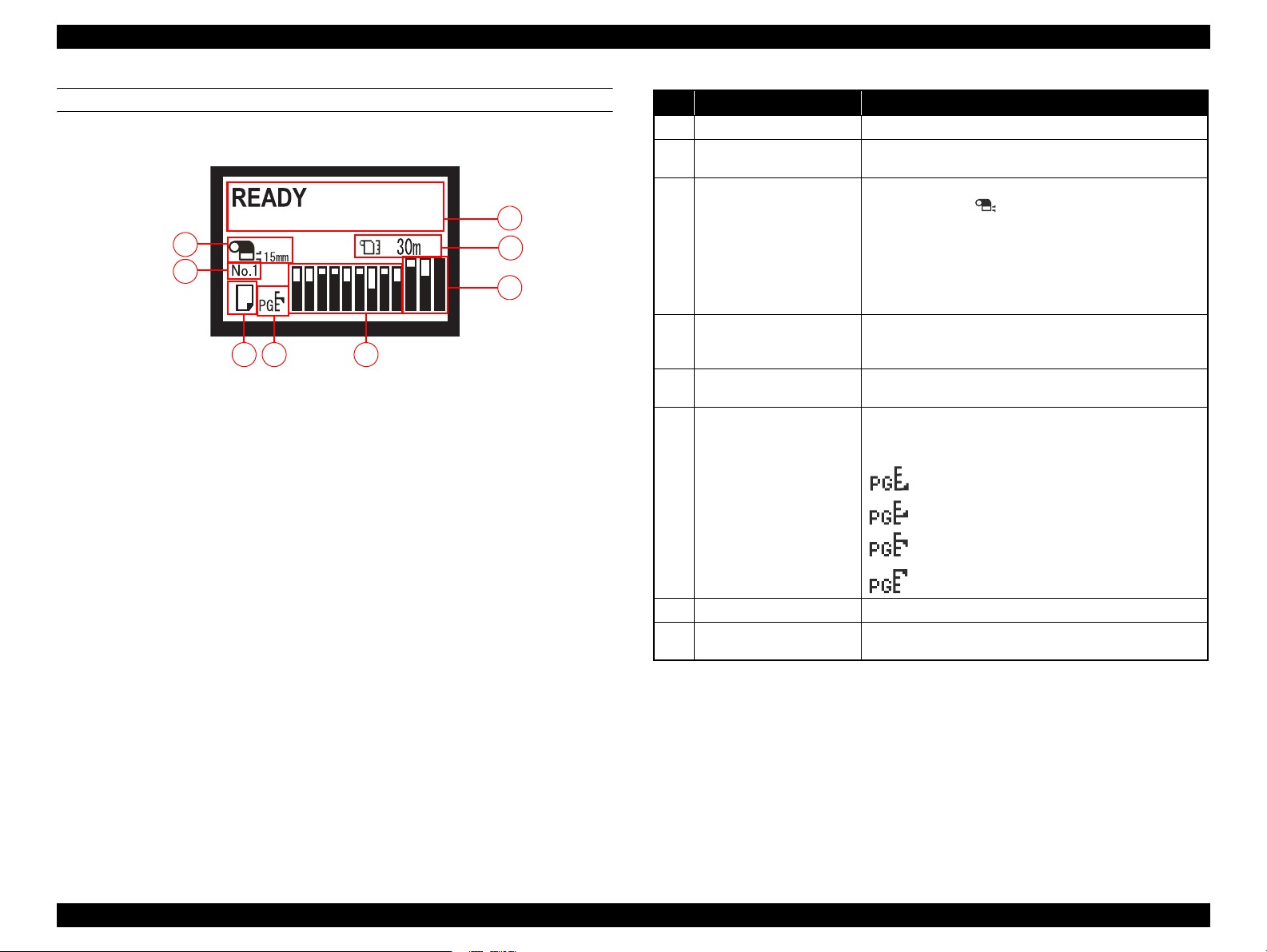
LCD
Normal indication
3
4
6
5
7
Figure 1-5. LCD (Normal indication)
No. Item Description
Message Printer status, operating status, or an error message is displayed.
1
Remaining amount of roll
2
paper
1
ROLL PAPER MARGIN
2
3
settings
8
Registered “CUSTOM
4
PAPER” No.
Paper type and roll paper cut
5
setting
“PLATEN GAP” setting
6
The remaining length of the roll paper is displayed.
The setting made by the ROLL PAPER MARGIN menu is
indicated beside the .
• 15mm: “TOP/BOTTOM 15 mm” is selected.
• 35/15mm: “TOP 35/BOTTOM 15 mm” is selected.
• 3mm: “3mm” is selected.
• 15mm: “15mm” is selected.
Nothing appears when the “DEFAULT” is selected for the ROLL
PAER MARGIN.
When the paper type registered using “PAPER NO.1 ñ 10” in the
“CUSTOM PAPER” is selected, the registered number is
displayed.
Selected paper type (cut sheet or roll) and roll paper cut settings is
displayed.
“PLATEN GAP” setting is displayed as shown below.
While the registered number of the “CUSTOM PAPER” is
displayed, the “PLATEN GAP” setting is not displayed.
: “NARROW” is selected.
: “WIDE” is selected.
: “WIDER” is selected.
: “WIDEST” is selected.
Ink level The current ink level in each of the nine cartridges is indicated.
7
Waste ink level in the
8
maintenance tanks
The current waste ink level in each of the three maintenance tanks
is indicated.
PRODUCT DESCRIPTION Control Panel 27
Page 28
EPSON Stylus Pro 11880/11880C Revision A
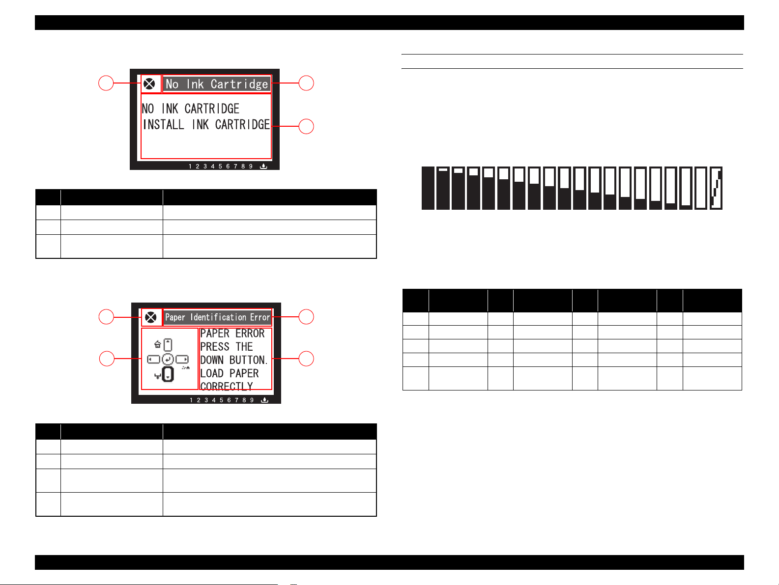
Error indication
12
3
Figure 1-6. LCD (Error indication)
No. Item Description
Error name An error name is displayed inverted.
1
Error icon An error icon is displayed.
2
Remedy
3
Note : When multiple errors are occurring simultaneously, the errors are indicated in the order of preset
priority. After recovering one of the error, the next error is displayed.
An explanation about the error or an instruction to recover from
the error is displayed.
LCD (Error indication with an image)
2
1
3 4
ICONS ON THE LCD
Ink level Indicator
Indicator
The current ink level in each of the nine cartridges is indicated. The
following figure and table explain the relation between the indicated
level and the actual level.
12 4 5678 91011
3
12
Figure 1-8. Ink level Indicator
Table 1-9. Ink Level Indicator and Actual Ink Level
Actual Level
No.
1 95-100 6 67-72 11 39-44 16 12-16
2 89-94 7 62-66 12 34-38 17 6-11
3 84-88 8 56-61 13 28-33 18 1-5
4 78-83 9 51-55 14 23-27 19 Empty
5 73-77 10 45-50 15 17-22 20
(%)
No.
Actual Level
(%)
No.
14
13
15
Actual Level
(%)
16 17 18 19 20
No.
Actual Level
(%)
Ink cartridge
error
Figure 1-7. LCD (Error indication with an image)
No. Item Description
Error name An error name is displayed inverted.
1
Error icon An error icon is displayed.
2
Image
3
Remedy
4
Note : When multiple errors are occurring simultaneously, the errors are indicated in the order of preset
priority. After recovering one of the error, the next error is displayed.
An illustration that demonstrates the explanation or instruction
for the error is displayed.
An explanation about the error or an instruction to recover from
the error is displayed.
PRODUCT DESCRIPTION Control Panel 28
Page 29

EPSON Stylus Pro 11880/11880C Revision A
Waste ink level in the maintenance tanks
Indicator
The waste ink level in each of the three maintenance tanks are
indicated. The following figure and table explain the relation between
the indicated level and the actual level.
Figure 1-9. Maintenance Tank Waste Ink Level Indicator
Table 1-10. Waste Ink Level and Actual Level
No.
1
2
3
4
5
6
7
8
Actual Level
(%)
96-100
91-95
86-90
81-85
77-80
72-76
67-71
62-66
No. Actual Level (%) No. Actual Level (%)
10
11
12
13
14
15
16
9
58-61
53-57
48-52
43-47
39-42
34-38
29-33
24-28
17
18
19
20
21
22
23
20-23
15-19
10-14
5-9
1-4
0
Full
PRODUCT DESCRIPTION Control Panel 29
Page 30
EPSON Stylus Pro 11880/11880C Revision A
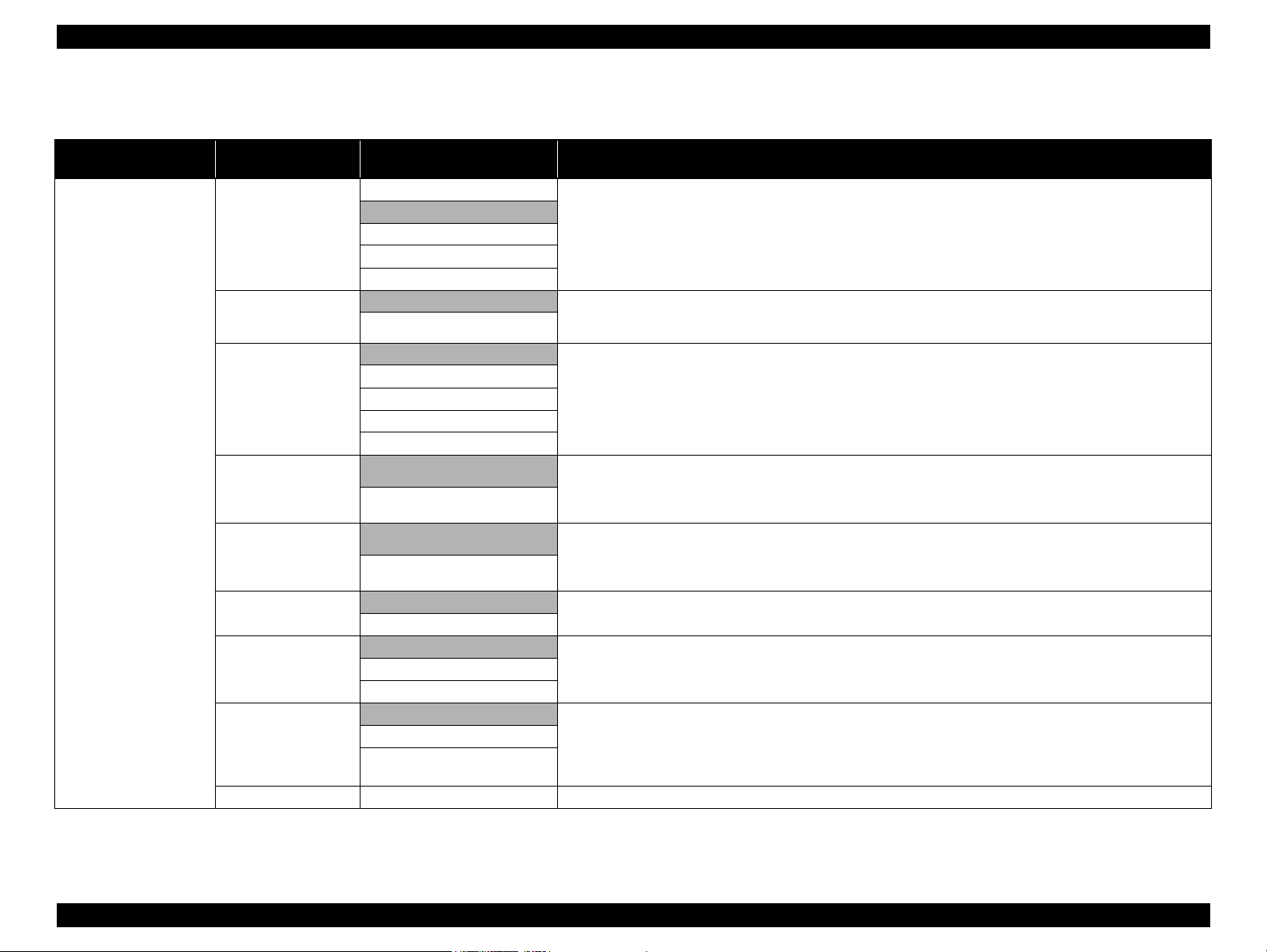
1.5.1 Menu Mode Settings
Table 1-11. Menu Mode Settings List
Top Menu Menu Item
PRINTER SETUP
PLATEN GAP
PAGE LINE
ROLL PAPER MARGIN
PAPER SIZE CHECK
PAPER SKEW CHECK
REFRESH MARGIN
AUTO NOZZLE
CHECK
PRINT NOZZLE
PATTERN
INITIALIZE SETTING
(shaded one is the default)
TOP 35/BOTTOM 15mm
Settings
NARROW
STANDARD
WIDE
WIDER
WIDEST
ON Sets whether to print a page line (line for manual cutting) on roll paper or not.The page line is printed when ON is selected.
OFF
DEFAULT
TOP/BOTTOM 15mm
15 mm
3 mm
ON
OFF
ON
OFF
ON
OFF
ON: PERIODICALLY
OFF
OFF The printer prints a nozzle check pattern automatically at the specified timing.This setting is available only when roll paper is
ON: EVERY PAGE
ON: EVERY 10 PAGES
EXECUTE All the settings made using the control panel are returned to their default.
Sets the platen gap (gap between the printhead and the platen).
When the “Others” is selected in the PAPER TYPE of the CUSTOM PAPER menu, the platen gap designated at the
CUSTOM PAPER menu has a priority over the setting made here. Refer to "PG Settings List" on page 35.
When the roll paper width specified by the printer driver is narrower than that loaded on the printer, vertical page lines are
printed.
Sets the margins for roll paper.
When the Default is selected, the top margin becomes 20mm and the bottom margin becomes 15mm for the following paper
types; Premium Glossy Photo Paper(250), Premium Semigloss Photo Paper(250), and Premium Luster Photo Paper(260).
When borderless printing is specified, this setting is ignored and the all margins become 0mm.
Sets whether to detect the paper width or not.
Setting to OFF deactivates the sensor that detects the paper width when paper is loaded on the printer. This allows the user to
use paper whose width is out of the sensor’s detectable range. It means that the user can print an image larger than the paper
size. The user should know that doing so soils the platen and may cause a print quality or any other trouble.
Sets whether to detect the paper skew or not.
Setting to OFF does not carry out the detection and printing is continued even if the paper is skewed. When this setting is set
to OFF, the user should have known the risk.
This setting is not available for cut sheet because the skew detection function after printing is not provided for cut sheet.
When this is set to ON, the top edge area of paper soiled by the previous borderless printing is automatically cut off.
The printer runs a nozzle check automatically at the specified timing.ON: EVERY JOB
used.
When the set number of pages is reached, the nozzle check pattern is printed on the top of the page. The counter for counting
the pages is not reset even by power-off.When this setting is changed, the counter is cleared. Printing patterns preset in the
printer is not counted except the network status sheet.
Explanation
PRODUCT DESCRIPTION Control Panel 30
Page 31

EPSON Stylus Pro 11880/11880C Revision A
Table 1-11. Menu Mode Settings List
Top Menu Menu Item
TEST PRINT
MAINTENANCE
PRINTER STATUS
PRINTER STATUS
(shaded one is the default)
NOZZLE CHECK PRINT
STATUS SHEET PRINT Prints an information on the printer status.
NETWORK STATUS
SHEET
JOB INFORMATION PRINT Prints a print job history report (up to 10 jobs) that is stored in the printer.
CUSTOM PAPER PRINT Prints the settings made in the CUSTOM PAPER menu.
CUTTER
ADJUSTMENT
CUTTER
REPLACEMENT
POWER CLEANING EXECUTE Runs a power cleaning that is stronger than the normal cleaning.
CLEAN EACH COLOR
CLOCK SETTING MM/DD/YY HH:MM Sets the date and time for the internal clock.
CONTRAST
ADJUSTMENT
VERSION F0xxxx-xx.xx.IBCC Displays the firmware version. Refer to "Firmware version information" on page 36.
PRINTABLE PAGES (ink color) nnnnnnn PAGES Displays the number of pages printable with the installed ink cartridges.
INK LEVEL (ink color) nn% Displays the ink level in the installed ink cartridges.
MAINTENANCE TANK
USAGE COUNT
CLEAR USAGE
COUNT
Settings
Prints a nozzle check pattern, the firmware version, paper/ink consumption, and waste ink level in the maintenance
tanks.Visually check the printout patterns for any missing lines or segments. If missing lines or segments are observed, run a
manual cleaning as necessary.
PRINT Prints an information on the network status.
EXECUTE
EXECUTE Runs a cutter replacement sequence.
C/VM
PK
MK/Y
LLK/LK
VLM/LC
0
-20 - 0 - +20 (dec)
LEFT nn%
RIGHT nn%
INK xxxxx.xml Displays the total amount of consumed ink in ml unit.
PAPER xxxxx.xcm Displays the total roll paper length consumed in cm unit.
INK EXECUTE Resets the USAGE COUNT counter for ink to its default.
PAPER EXECUTE Resets the USAGE COUNT counter for paper to its default.
Adjusts the built-in cutter position.
A cutter position adjustment pattern is printed. Examine the printout patterns and select the number for the best pattern.
Runs a cleaning for the specified nozzle columns.
Adjusts the contrast of the LCD on the control panel.
Displays the waste ink level in the installed maintenance tanks.CENTER REAR nn%
Explanation
PRODUCT DESCRIPTION Control Panel 31
Page 32

EPSON Stylus Pro 11880/11880C Revision A
Table 1-11. Menu Mode Settings List
Top Menu Menu Item
PRINTER STATUS
PAPER SETUP
(shaded one is the default)
JOB HISTORY
TOTAL PRINTS nnnnnn PAGES Displays the total printed pages using 6-digit decimal number.
NOT STARTED, ENABLED,
EDM STATUS
MM/DD/YY HH:MM GMT
PAPER TYPE
REMAINING PPR SETUP
ROLL PAPER
REMAINING
CUSTOM PAPER PAPER NO.1 - 10
PAPER TYPE
Settings
No.0 to No.9
Ink xxxxx.xml
Paper xxx.x cm2
DISABLED
LAST UPLOADED
(NOT UPLOADED)
Photo Paper
Fine Art Paper
Matte Paper
Plain paper
Others
CUSTOM PAPER
NO PAPER SELECTED
ROLL PAPER LENGTH
ROLL LENGTH ALERT
Photo Paper
Fine Art Paper
Matte Paper
Plain paper
Others
Explanation
Job No.
Displays the job number that is stored in the printer.The latest job number is 0 (zero).
The amount of ink consumed
Displays the amount of ink consumed for each job.
The amount of paper consumed
Displays the total area of paper used for each job.
Displays the EDM status.
Sets the paper type loaded on the printer.
Sets whether and when to count the remaining amount of paper.
OFF: Disables the roll paper remaining amount count function.
ON: PRINT EVERY PAGE: Displays the roll paper remaining amount on the LCD. Each time a print job is finished,
a barcode that includes information on PAPER TYPE, PAPER LENGH, and ROLL_LENGTH_ALERT settings.
ON: AT ROLL EXCHANGE: Displays the roll paper remaining amount on the LCD. When roll paper is replaced with a new
one and the [Enter] button is pressed for more than 3 seconds, the Paper Lever is locked and a barcode includes
information on PAPER TYPE, PAPER LENGH, and ROLL_LENGTH_ALERT settings is printed on the top of the
paper. The printer reads the barcode and automatically applies the read settings for the new roll paper.
Sets roll paper length, and the remaining length of roll paper to be alerted when the set amount is reached. The printer displays
the roll paper remaining amount and the alert on the control panel according to the settings made here.
The user can register custom paper settings up to 10. The custom paper settings include PAPER TYPE, PLATEN GAP,
THICKNESS PATTERN, CUT METHOD, PAPER FEED ADJUST,DRYING TIME, PAPER SUCTION settings.
Selects the paper type.
PRODUCT DESCRIPTION Control Panel 32
Page 33

EPSON Stylus Pro 11880/11880C Revision A
Table 1-11. Menu Mode Settings List
Top Menu Menu Item
PAPER SETUP
PAPER SETUP
HEAD ALIGNMENT
(shaded one is the default)
PLATEN GAP
THICKNESS PATTERN PRINT Prints a pattern for checking the thickness of the loaded paper.
CUT METHOD
PAPER FEED ADJUST
DRYING TIME
PAPER SUCTION
PAPER THICKNESS
ALIGNMENT
Settings
NARROW
STANDARD
WIDE
WIDER
WIDEST
STANDARD
THIN PAPER
THICK PAPER, FAST
THICK PAPER, SLOW
0.00% Adjusts the paper feed line pitch.
-0.70% to +0.70%
0.0 SEC
0.0 SEC to 10.0 SEC
STANDARD
-1 to -4
SELECT PAPER TYPE Sets thickness of paper to be used.
SELECT THICKNESS
AUTO Sets whether to carry out the head alignment adjustment automatically or manually.
MANUAL
Adjusts the platen gap (gap between the printhead and paper surface) according to the paper thickness.
STANDARD: use this setting under normal conditions
NARROW: select this when using thin paper.
WIDE, WIDER: select this when smudges or blurring appear due to an excess pressure on the paper.
WIDEST: select this when using heavy paper.
Selects the auto cut setting.
The larger the value is, the more the possibility to cause white bands on printout image.
The smaller the value is, the more the possibility to cause black bands on printout image.
Sets a time period to pause the carriage movement for drying the printed surface. Depending on paper type and density, drying
ink may take longer. Check the result and set longer time period in such case.
Sets the power level of the suction fan.
• When Epson paper is used, select the paper type.
• When not Epson paper is selected, enter the thickness of the selected paper.
AUTO:
The adjustment is carried out automatically after the adjustment pattern is printed.
MANUAL:
Select this to carry out the adjustment manually (visually check the patterns and enter selected values) after printing the
adjustment pattern.
Explanation
PRODUCT DESCRIPTION Control Panel 33
Page 34

EPSON Stylus Pro 11880/11880C Revision A
Table 1-11. Menu Mode Settings List
Top Menu Menu Item
NETWORK SETUP
NETWORK SETUP
IP ADDRESS SETTING
IP, SM, DG SETTING
BONJOUR
INIT NETWORK
SETTING
(shaded one is the default)
ADDRESS
SUBNET
MASK
DEFAULT
GATEWAY
Settings
DISABLE
ENABLE
AUTO
PANEL
000.000.000.000
IP
ON
OFF
EXECUTE Returns the network settings to their default.
-
255.255.255.255
192.168.192.168
000.000.000.000
-
255.255.255.255
255.255.255.000
000.000.000.000
-
255.255.255.255
255.255.255.255
Enables or disables the network settings.
The NETWORK SETUP menu items appear on the LCD only when this is set to ENABLE.
Sets whether to set the IP address automatically or manually.
When the PANEL is selected, the IP, SM, DG SETTING menu is enabled to enter the address manually.
Sets the IP address, subnet mask, and default gateway manually.
Enables or disables the BONJOUR.
Explanation
PRODUCT DESCRIPTION Control Panel 34
Page 35

Stylus Pro 11880/11880C Revision B
PG Settings List
The table below shows the actual platen gap amount specified by the printer driver
or the control panel.
Table 1-12. PG Settings List
Paper
Thickness
Sensor
0.3 mm or
lower
Paper Thickness
Setting by Driver
No setting
0.0 to 0.8mm
0.9mm to 1.5mm -- -- 2.6
Menu Setting
NARROW
STANDARD
WIDE
WIDER
Widest
Media Table or Printer
Driver PG Setting
Narrow 0.8
Standard 0.8
Wide 1.2
Wider 1.6
Widest 2.1
Narrow 0.8
Standard 1.2
Wide 1.6
Wider 2.1
Widest 2.6
Narrow 1.2
Standard 1.6
Wide 2.1
Wider 2.6
Widest 2.6
Narrow 1.6
Standard 2.1
Wide 2.6
Wider 2.6
Widest 2.6
Narrow 2.1
Standard 2.6
Wide 2.6
Wider 2.6
Widest 2.6
PG Values
(mm)
Paper
Thickness
Sensor
0.4mm to
0.6mm
0.7mm to
2.0mm
Table 1-12. PG Settings List
Paper Thickness
Setting by Driver
No setting
0.0 to 0.8mm
0.9mm to 1.5mm -- -- 2.6
-- -- -- 2.6
Menu Setting
NARROW
STANDARD
WIDE
WIDER
WIDEST
Media Table or Printer
Driver PG Setting
Narrow 0.8
Standard 0.8
Wide 1.2
Wider 1.6
Widest 2.1
Narrow 0.8
Standard 1.2
Wide 1.6
Wider 2.1
Widest 2.6
Narrow 1.2
Standard 1.6
Wide 2.1
Wider 2.6
Widest 2.6
Narrow 1.6
Standard 2.1
Wide 2.6
Wider 2.6
Widest 2.6
Narrow 2.1
Standard 2.6
Wide 2.6
Wider 2.6
Widest 2.6
PG Values
(mm)
PRODUCT DESCRIPTION Control Panel 35
Page 36

Stylus Pro 11880/11880C Revision B
Firmware version information
The table below explains the firmware version information (F0XXXXxx.xx.IBCC) printed by selecting the VERSION in the PRINTER STATUS menu.
Table 1-13. Firmware Version Information
Item Explanation
F0
XXXX Indicates the firmware version installed on the printer.
xx.xx Indicates the network firmware version.
I "8" is indicated for Stylus Pro 11880/11880C.
B
C
A code assigned to each printer.
"0" (zero) is assigned to a special version of printer.
Indicates the available functions for business system. “1 to F” hexadecimal
number appears according to the combination of available functions. When
"0" is assigned to each of the three bits, "0" is indicated. "3" is indicated for
Stylus Pro 11880/11880C because the printer does not support the business
system functions.
bit0: Graphic printing control function
0: Disabled
1: Enabled
bit1: Credit function
0: Disabled
1: Enabled
bit2: Credit counter
0: Disabled or the counter is
1: Enabled and the counter is “1” or above.
bit3: Reserved
A hexadecimal number (00H-FFH) appears to indicate the specified custom
number that registers special operation setting. When no custom operation is
"00"
specified,
appears.
"0"
.
PRODUCT DESCRIPTION Control Panel 36
Page 37

Stylus Pro 11880/11880C Revision B
1.5.2 Maintenance Mode
The maintenance mode allows you to change the environmental settings such as
language and unit settings to be displayed, or to return the all settings to their default.
The user can also access this mode.
HOW TO START & QUIT
1. While holding down the [Pause/Reset] button, turn the printer On. The printer
starts up in the maintenance mode.
2. Turn the printer Off to quit the maintenance mode.
MAINTENANCE MODE MENU LIST
Settings
Menu Item
LANGUAGE
UNIT
CUT PRESSURE
SS CLEANING
PWR ON ROLL PPR
FEED
DEFAULT PANEL
CUSTOM
(shaded one is the
default)
ENGLISH
JAPANESE
FRENCH
GERMAN
ITALIAN
PORTUGUE
SPANISH
DUTCH
METRIC
FEET/INCH
0 - 150%
EXECUTE
ON
OFF
EXECUTE
0 - 255
Explanation
Selects the language used for the control panel
display.
Selects a unit of length to be used for various
length information.
Specifies a cut pressure of the auto cutter.
Runs a supersonic cleaning.
Sets whether to feed roll paper or not at
power-on when the cutter setting is off.
Setting to OFF saves the roll paper.
Returns the all settings made by the control
panel to their default.
Stores custom settings.
PRODUCT DESCRIPTION Control Panel 37
Page 38

Stylus Pro 11880/11880C Revision B
1.5.3 Serviceman Mode
The serviceman mode is intended to be used by a service personnel for servicing the printer.
HOW TO START & QUIT
1. Turn the printer on by pressing the [Pause/Reset], [Paper Feed/Down], and [Menu/Right] buttons.
2. Turn the printer off to quit the serviceman mode.
SERVICEMAN MODE MENU LIST
Menu
Distinction 1 2 3
Test Version F/W Displays the F/W version.
BOOT Displays the BOOT version.
Param 1 Displays the NVRAM (Area with assurance of power failure) version.
Param 2 Displays the NVRAM (Area without assurance of power failure) version.
DipSW Displays the status of the Dip switch.
Panel Key Checks the operations of the buttons of the control panel.
LCD Checks the operations of the LCD of the control panel.
LED Checks the operations of the LEDs of the control panel.
Ink LED Checks the operations of the LEDs of the Ink Holder.
Sensor Paper Thick Checks the operations of each sensor.
Paper Lever
Ink Button
Ink Cvr
Cover
M Tank
Ink Not
Rear AD
Auto Reel Sens.
Auto Reel Connect
Head Temp
Explanation
PRODUCT DESCRIPTION Control Panel 38
Page 39

Stylus Pro 11880/11880C Revision B
Menu
Distinction 1 2 3
Test Sensor Drv Temp Checks the operations of each sensor.
AutoChk
Encoder CR PF Checks the operations of the CR/PF encoder sensor.
Fan Paper (All) Checks the operations of each fan.
Paper (Duty)
Paper 1
Paper 2
Paper 3
Paper 4
HT Fan
Error History Error 0 Displays the error history.
Error 1
Error 2
Error 3
Error 4
Error 5
CSIC M TANK R/C/L Checks the communication status with the CSIC of the Maintenance Tank.
Cut Adj. Performs a cutter pressure adjustment.
Actuator 2 Cutter Sol. Checks the operations of each actuator.
Ink Cover Sol.
Lever Lock Sol.
Ink Press Motor
Select Valve
Cap Motor
Auto Reel Motor
Edge Sns Lv1 Measures the detection level of the Paper Width Sensor.
Cap UnCap UnCap Moves the cap.
Cap
Explanation
PRODUCT DESCRIPTION Control Panel 39
Page 40

Stylus Pro 11880/11880C Revision B
Menu
Distinction 1 2 3
Adjustment PG Adjust UnCap Operates the platen gap mechanism.
Cap
AID PG Performs an AID Inspection PG Adjustment.
Fan Paper (All) Checks the operations of the Suction Fan.
Fan Adjust Adjusts the suction level.
Paper Adjusts the Paper Thickness Sensor.
Rear AD Adjusts the AD values of the P Rear Sensor.
Init. Fill Performs an initial ink charge.
Nozzle Check Output Pattern Prints a nozzle check pattern.
Nozzle Alignment Output Pattern Prints a nozzle alignment pattern.
PG Select Adjusts the platen gap.
Cutter Checks the cutting position.
Rear Sens. Pos Corrects the position of the P Rear Sensor.
Ink Cover Sol Adjusts the duty of the solenoid.
Head Slant CR Head Slant Adjusts the slant of the printhead.
PF Head Slant
UnCap
Cap
IM Sensor Performs the sensitivity adjustment, the position adjustment, and the detection
check of the Ink Mark Sensor.
Belleta Pos Belleta Pos. Adj. Adjusts the platen position.
Belleta Pos. Confirm Checks the platen position.
Skew Check Checks the skew of the paper.
Feed Adj.+ T&B Performs band feed adjustment and T&B adjustment.
Gap Adj. Auto Auto ALL Prints an auto adjustment pattern.
Auto Uni-D
Auto Bi-D
Explanation
PRODUCT DESCRIPTION Control Panel 40
Page 41

Stylus Pro 11880/11880C Revision B
Menu
Distinction 1 2 3
Adjustment Gap Adj. Manual Uni-D ALL Prints a manual Uni-D adjustment pattern and enters the adjustment value.
VSD1
VSD2
VSD3
VSD4
Manual Bi-D PG1.6 PG1.6 ALL Prints a manual Bi-D adjustment (PG1.6) pattern and enters the adjustment value.
VSD1
VSD2
VSD3
VSD4
Manual Bi-D PG0.8 PG0.8 ALL Prints a manual Bi-D adjustment (PG0.8) pattern and enters the adjustment value.
VSD1
VSD2
VSD3
VSD4
AID Checks the AID function.
Print Adj. Variable 1 Prints the adjustment variables.
Print Adj. Variable 2 Prints the adjustment variables.
Clean Head Remote INK Runs a head cleaning.
Suction Wiping Performs a wiping operation.
Print Head Exchange Drain Performs an ink discharge.
Head Exchange Moves the printhead to its exchange position.
Explanation
PRODUCT DESCRIPTION Control Panel 41
Page 42

OPERATING PRINCIPLES
CHAPTER
2
Page 43

Stylus Pro 11880/11880C Revision B
2.1 Overview
This chapter explains the operating principles for this printer.
The major components of this printer’s mechanism are shown below.
Electric Circuit Boards
Table 2-1. List of Electric Circuit Boards
Fig. Name Function
Right LED Board
1
Sub Board Assy Relays the connection between the Main Board Assy and the
2
Left LED Board
3
Sub Board Assy; E
4
Sub Board Assy; C Relays the connection between the Main Board Assy and the
5
Power Supply Board Assy
6
Main Board Assy
7
Indicator for the Ink Cover
Ink Cover Open Switch
following parts.
PG HP Sensor
Ink Mark Sensor
Paper Width Sensor
CR Encoder Sensor
CR HP Sensor
Printhead
Cutter Solenoid
Indicator for the Ink Cover
Ink Cover Open Switch
Relays the connection between the Main Board Assy
and the following parts.
Ink Cartridge
Left LED Board
following parts.
Maintenance Tank
PF Encoder
Generates the voltage for this printer from the AC
power supply.
Communicates with the computer.
Processes received data.
Controls the printer mechanism.
Stores the correction values and various counters.
Generates the voltages for the logic system from the
voltage of 42V supplied from the Power Supply Board
Assy.
Table 2-1. List of Electric Circuit Boards
Fig. Name Function
Sub Board Assy; B Relays the connection between the Main Board Assy and the
8
Sub Board Assy; D Relays the connection between the Main Board Assy and the
9
v
Panel Board
10
following parts.
Maintenance Tank
Paper Thickness Sensor
P Rear Sensor
Ink System Unit
following parts.
Ink Cartridge
Right LED Board
For operations and settings of the printer
Displays the status of the printer and the values of various
settings on the LCD.
Indicates the status of the printer with the LED.
6
7
5
4
3
2
Figure 2-1. Layout of Electric Circuit Boards
8
9
10
1
OPERATING PRINCIPLES Overview 43
Page 44

Stylus Pro 11880/11880C Revision B
Motors/Solenoids
Table 2-2. List of Motors/Solenoid
Fig. Name
Ink Cover Lock Solenoid (R/L) ---
1
Take-up Motor Auto Take-up Reel Unit
2
Cutter Solenoid ---
3
Suction Fan ---
4
PF Motor Grid Roller
5
Pressure Motor Pressure Pump
6
Lever Lock Solenoid ---
7
Cap/Wiper Motor
8
Pump Motor Pump Unit
9
v
APG Motor Platen gap mechanism
10
CR Motor Carriage Unit
11
Type: DC solenoid
Voltage: +42 V
Type: DC motor
Voltage: +42 V
Type: DC solenoid
Voltage: +24 V
Type: DC blower fan
Voltage: +24 V
Type: DC motor
Voltage: +42 V
Type: DC motor
Voltage: +42 V
Type: DC solenoid
Voltage: +24 V/+5V
Cap
Wiper
Type: stepping motor
Voltage: +42 V
Type: stepping motor
Voltage: +42 V
Type: stepping motor
Voltage: +42 V
Type: DC motor
Voltage: +42 V
Driven Parts
Specifications
6
5
CR
4
3
Figure 2-2. Layout of Motors/Solenoid
8
7
11
2
9
10
11
OPERATING PRINCIPLES Overview 44
Page 45

Stylus Pro 11880/11880C Revision B
Sensors/Encoders
Table 2-3. List of Sensors/Encoders
Fig. Name
Right Ink Cover Sensor Detects the opening/closing status of the Right Ink
1
Right Front Cover Sensor Detects the opening/closing status of the Right
2
Slack Detection Sensor Detects the slack of the ejected roll paper.
3
CR HP Sensor Detects the home position of the Carriage Unit.
4
CR Encoder Sensor Read the value of the CR Scale.
5
Paper Width Sensor Detects the width of the paper.
6
PG HP Sensor Detects the home position of the platen gap.
7
Ink Mark Sensor
8
Left Front Cover Sensor Detects the opening/closing status of the Left
9
Left Ink Cover Sensor Detects the opening/closing status of the Left Ink
10
PF Encoder Sensor Read the values of the PF Scale.
11
Pressure Rotary Encoder Sensor Detects the revolution status of the Pressure
12
Cover.
Type: Leaf switch
Front Cover.
Type: Leaf switch
Type: Transmissive optoelectronic sensor
Type: Transmissive photo interrupter
Type: Transmissive photo interrupter
Type: Reflective photo interrupter
Type: Transmissive photo interrupter
Auto Bi-D adjustment
Auto Uni-D adjustment
Auto nozzle check
Detects the remaining amount of the roll paper.
Type: Reflective photo interrupter
Front Cover.
Type: Leaf switch
Cover.
Type: Leaf switch
Type: Transmissive photo interrupter
Motor.
Type: Transmissive photo interrupter
Function
Specifications
Table 2-3. List of Sensors/Encoders
Fig. Name
Pressure Sensor Detects the pressurizing status of the Pressure
13
P Rear Sensor Detects the presence of the paper.
14
Paper Thickness Sensor Detects the thickness of the currently set paper.
15
Pump Sensor Detects the operating status of the Pump Unit.
16
Cap Unit HP sensor Detects the positions of the components of the Ink
17
12
12
13
Pump.
Type: Transmissive photo interrupter
Type: Reflective photo interrupter
Type: Transmissive photo interrupter
Type: Transmissive photo interrupter
System Unit.
Type: Transmissive photo interrupter
12
11
10
5
6
Function
Specifications
14 15 15
I/S
CR
34789
Figure 2-3. Layout of Sensors/Encoders/CSIC
16
17
12
OPERATING PRINCIPLES Overview 45
Page 46

Stylus Pro 11880/11880C Revision B
2.2 Print Mechanism
This section explains the basic specifications of the printhead.
This printhead has ten rows of nozzles, and employs a row of nozzles per color. (one of
the rows is not in use.)
Printing method: On-demand ink-jet
Nozzle configuration: 360 nozzles x 9 rows = 3,240 nozzles
Colors:
Nozzle Row Color
A
B
C
D
E
F
G
H
I
J
Cyan
Vivid Magenta
N/A
Photo Black
Matt Black
Yellow
Light Light Black
Light Black
Light Cyan
Vivid Light Magenta
Drive Waveforms:
Waveform
Name
VSD1 10.8 360 x 360
VSD2 8.64 720 x 720 240
VSD3 8.64 1440 x 720
VSD4 8.64 2880 x 1440 240
Drive Frequency
(kHz)
Print Resolution
(dpi)
720 x 360
720 x 720
1440 x 1440
Paper Feed Direction
Carriage Moving Direction
Figure 2-4. Nozzle Configuration
CR Speed
(cps)
300
240
OPERATING PRINCIPLES Print Mechanism 46
Page 47

Stylus Pro 11880/11880C Revision B
2.3 Ink Supply Mechanism
The ink supply mechanism consists of the Ink Cartridge, Ink Holder, and Pressure
Pump Unit.
Ink Cartridge
This is the cartridge that contains ink, and equipped with the CSIC that stores the
information on detecting attachment of the cartridge, the type of ink and life etc.
Ink Holder
This is the holder that the Ink Cartridges are installed and relays the connection
between the Ink Cartridges and the Ink Tubes/Pressure Pump Tubes.
Pressure Pump Unit
This is the unit to stabilize the supply of ink from the Ink Cartridge (Ink Pack) to the
printhead. The ink stored in the Ink Pack is supplied to the printhead by sending the air
from the Pressure Pump Unit to the sealed Ink Cartridge so as to apply pressure to the
Ink Pack.
Ink Holder
Pressure Pump Unit
Carriage Unit
Ink Cartridge
Ink Holder
Figure 2-5. Ink Supply Mechanism
OPERATING PRINCIPLES Ink Supply Mechanism 47
Page 48

Stylus Pro 11880/11880C Revision B
2.4 Cleaning Mechanism
The cleaning mechanism consists of the Maintenance Tanks, the Ink System Unit and
the AID function.
Maintenance Tank
This is the tank that retrieves (absorbs) the waste ink. This printer is equipped with
three Maintenance Tanks.
• HP side:
for the waste ink at capping, flushing, and borderless-printing of less than 24
inch
• Center:
for the waste ink at borderless-printing of over 728 mm to 44 inch
• Left side (opposite to HP):
for the waste ink at borderless-printing of over 44 inch
Ink System Unit
The Ink System Unit consists of the Cap, Flushing Box, Wiper, Pump, and the Carriage
Lock. The positions of these parts are changed by the drive of the Cap/Wiper Motor.
The control of this positioning change is monitored by the Cap Unit HP Sensor.
Cap Unit
This is the unit that protects the nozzle surface of the printhead. It is equipped
with five caps and each cap is used for every two rows of nozzles.
Pump
This is the unit to suck ink from the nozzles. It is driven by the Pump Motor.
Carriage Lock
This is the part that locks the Carriage Unit. It is driven by the Cap/Wiper
Motor.
Flushing Box
Wiper
Pump
Flushing Box
This is the box to receive ink at flushing. The box is mobile and stored at the
rear of the Ink System Unit when unused. When in use, it is automatically
moved to the specified position by the Cap/Wiper Motor.
Carriage Lock
Wiper
This cleans the nozzle surface of the printhead by wiping it. The Ink System
Cap Unit
Unit is equipped with two wipers (the one for all nozzles and the other for one
nozzle).
Figure 2-6. Ink System Unit
OPERATING PRINCIPLES Cleaning Mechanism 48
Page 49

Stylus Pro 11880/11880C Revision B
AID (Auto Ink droplet Detection) Function
This is the function that detects the dot-missing automatically. Voltage is applied to the
Flushing Box from the DC-DC converter on the AID Board (BOARD ASSY.,HEAD).
This voltage application generates the electric field at the space between the nozzle
Flushing Box
plate of the printhead and the Flushing Box. The ink discharged from the nozzles is
electrically charged while dropping through the generated electric field. Since the ink
is charged, the landing of the drop of ink on the Flushing Box can be detected
electrically. Discrimination of the nozzles with dot-missing becomes possible, since
whether the discharged drop of ink lands or not can be detected by each nozzle level.
In the case that dot-missing occurs, the cleaning is executed automatically.
Wiper
Carriage Lock
Electric
Field
Cap/Wiper Motor
Cap Unit
AID Board
Flushing Box
Figure 2-8. Image of the AID Function
Figure 2-7. Operation of the Ink System Unit
OPERATING PRINCIPLES Cleaning Mechanism 49
Page 50

Stylus Pro 11880/11880C Revision B
2.5 Carriage Mechanism
The carriage mechanism is explained below.
2.5.1 Carriage Movement Mechanism
The mechanism that moves the carriage is explained below.
The carriage movement mechanism consists of the following components:
Carriage Unit
CR Motor
Timing Belt
CR Scale
CR Encoder Sensor
CR HP Sensor
PG HP Sensor
Rotational drive of the CR Motor is transmitted to the Carriage Unit through the
Timing Belt, and the Carriage Unit is moved left and right along the carriage guide
shaft. The CR Encoder Sensor installed on the back of the Carriage Unit reads the
jagged surface of the CR scale and sends the read values to the Main Board Assy. The
control of the position and the speed of the Carriage Unit are based on these read
values.
CR Encoder SensorPG HP Sensor
CR HP Sensor
Ink Mark Sensor
Paper Width Sensor
Figure 2-9. Carriage Movement Mechanism
OPERATING PRINCIPLES Carriage Mechanism 50
Page 51

Stylus Pro 11880/11880C Revision B
2.5.2 Platen Gap Adjustment Mechanism
The platen gap adjustment mechanism consists of the PG Motor, the Carriage Unit, and
the PG HP Sensor.
The drive of the PG Motor rotates the PG switching cam of the Carriage Unit through
the driven gears. Lifting or lowering the Carriage Unit by this rotation of the PG
switching cam adjusts the platen gap. The adjusting movement of the PG switching
cam (PG positions) is controlled with the PG HP Sensor by detecting the rotation of the
actuator mounted on the same shaft as the cam.
Sub carriage unit
Carriage Unit
PG switching
cam
PG HP Sensor
PG Motor’s drive
Actuator
Figure 2-10. Platen Gap Adjustment Mechanism
OPERATING PRINCIPLES Carriage Mechanism 51
Page 52

Stylus Pro 11880/11880C Revision B
2.6 Paper Feed Mechanism
OVERVIEW
Paper Feed Mechanism
The paper feed mechanism consists of the following components.
PF Motor
Timing Belt
PF Scale
PF Encoder Sensor
Grid roller
Suction Fan
P Rear Sensors
Paper Thickness Sensor
Paper Width Sensor
Rotation drive of the PF Motor is transmitted to the grid roller through the Timing Belt.
The control of the revolution speed and the steps of revolution are made with the PF
Encoder Sensor by reading the values of the PF Scale mounted on the same shaft as the
grid roller.
Timing Belt
PF Motor
Deceleration pulley
PF Encoder PF Scale
Figure 2-11. Paper Feed Mechanism
OPERATING PRINCIPLES Paper Feed Mechanism 52
Page 53

Stylus Pro 11880/11880C Revision B
Suction Fan
To stabilize the paper feeding, the fan sucks the air from inside of the printer, and
draws the paper to the platen.
Suction
Exhaust
排気
Figure 2-12. Suction Fan
P Rear Sensor
A reflective photo interrupter to detect the presence of the paper.
Paper Thickness Sensors (P THICK1/P THICK2)
Photo interrupters to detect the thickness of the currently set paper. The printer is
equipped with two sensors of this kind, and judges the thickness of the paper by
combining the detected data.
Table 2-4. Thickness of paper and the status of the sensors
Thickness
0.3mm or less Not shielded Not shielded
0.4mm to 0.6mm Shielded Not shielded
0.7mm to 2.0mm Shielded Shielded
Separation of the rollers Not shielded Shielded
P THICK1 P THICK2
Shielding Plate
Lever Lock Solenoid
The solenoid to lock the paper set lever.
P Rear Sensor
Paper Thickness Sensor
Lever Lock Solenoid
Figure 2-13. P Rear Sensor/Paper Thickness Sensor/Lever Lock Solenoid
OPERATING PRINCIPLES Paper Feed Mechanism 53
Page 54

Stylus Pro 11880/11880C Revision B
Paper Width Sensor
A reflective photo interrupter mounted on the Carriage Unit. It detects the paper based
on the difference of reflection between the paper and the platen and achieves the
following functions.
Paper width detection (left/right)
Top edge detection
Slant detection during printing
Cutter Solenoid
The solenoid to lower and retrieve the cutter to cut the roll paper.
Carriage Unit
ROLL PAPER RELATED
Take-up Motor
A motor to rewind the roll paper.
Slack Detection Sensor
An optoelectronic sensor to detect the slack of the roll paper. It consists of the sender/
receiver and the reflector. When the sensor detects the slack of the roll paper, the Takeup Motor rotates to rewind the paper.
Slack Detection Sensor (reflector)
Slack Detection Sensor (sender/receiver)
Figure 2-15. Slack Detection Sensor
Cutter
Cutter Solenoid
Figure 2-14. Paper Width Sensor/Cutter Solenoid
OPERATING PRINCIPLES Paper Feed Mechanism 54
Page 55

Stylus Pro 11880/11880C Revision B
2.7 Other Mechanisms
Front Cover Opening/Closing Detection Sensors
These sensors are mounted on both sides of the printer to detect the opening/closing
status of the Front Cover. When either of the sensors detects the opening status of the
cover, the CR Motor stops.
Ink Mark Sensor
This is a reflective photo interrupter with a sender and a receiver mounted on the
bottom surface of the Carriage Unit. The light emitted from the white LED reflects on
the paper or the printed special pattern on the paper. The receiver of the sensor reads
the reflected light, and the printer processes the correction based on the read data. The
functions of the Ink Mark Sensors are listed below.
Auto Bi-D adjustment
Acquires the value of the Bi-D correction automatically by detecting the peak
block of relative density from the printed special adjustment patterns.
Auto Uni-D adjustment
Acquires the value of the Uni-D correction automatically by detecting the
peak block of relative density from the printed special adjustment patterns.
Detection of the remaining amount of the roll paper
Checks the remaining amount of the roll paper by scanning the bar-code
printed on the paper.
OPERATING PRINCIPLES Other Mechanisms 55
Page 56

Stylus Pro 11880/11880C Revision B
2.8 Colorimetric Calibration (Color ID) Overview
This printer employs “Colorimetric Calibration (Color ID)” to correct unit-to-unit
variations in color.
Colorimetric Calibration (Color ID) corrects not only the weight of ink droplets which
differs depending on the individual characteristics of printhead but also variable factors
such as drive circuit and voltage. This enables a higher-accuracy calibration.
OVERVIEW
1. Printing/ Measuring the color of a correction pattern
A correction pattern printed by a completed product is used for the calibration.
A calibrator is used to perform the color measurement of the printed pattern.
2. Writing the correction value
Correction values are automatically calculated based on the result of the color
measurement and stored in the NVRAM on the main board.
3. Reflecting the correction value
Every time the printer makes a print, the printer driver reads out the correction
values from the NVRAM. Each ink droplet weight and the number of ink droplets
for each dot are corrected according to the information.
Main Unit
Printhead Main Board
Individual characteristic
of printhead
Drive Control
Circuit for
Printhead
Correction of the number of ink droplets
Correction of
ink droplet weight
Variation of elements on
the printhead control
circuit
Colorimetric Calibration
(Color ID)
Power Supply
Board
Variation in
voltage
applied to
printhead
Printout
Figure 2-16. Colorimetric Calibration (Color ID)
OPERATING PRINCIPLES Colorimetric Calibration (Color ID) Overview 56
Page 57

TROUBLE SHOOTING
CHAPTER
3
Page 58

Stylus Pro 11880/11880C Revision B
3.1 Overview
This section explains the basic procedure for troubleshooting problems on the printer
quickly and efficiently.
3.1.1 Preliminary Check
Make sure to verify or perform the following basic items whenever servicing the
printer.
1. There is no foreign material which interferes with the proper operation of the
printer.
2. Print the status sheet, and check the information printed on the sheet to find out
possible causes of the error; if the main units have reached their end of life, or if
there is something wrong with the user-defined panel settings.
3. Both outside and inside of the printer are free of significant dirt. Clean it if
significant dirt is observed.
4. None of the parts or components of the printer are missing, chipped or damaged.
5. All of the harnesses are free of damages and connected properly (vertically and
correctly) to their connectors.
6. The cams and gears in the printer mechanism are engaged correctly showing no
signs of wear.
7. When smudges appear on printed pages, clean the rubber rollers in the printer
mechanism if it solves the problem.
8. The rubber rollers in the printer mechanism are engaged correctly showing no
signs of wear.
W A R N I N G
C A U T I O N
When handling the lithium battery used for backup of the RTC on
the main board, strictly follow the safety instructions given in
"4.1.1 Precautions" (See P 76).
Before disassembling/reassembling the printer, be sure to turn
the power OFF, confirm the panel display disappears, and
unplug the power code.
Be sure to use the specified tools for maintenance/repair.
To maintain the product’s quality, be sure to use the specified
lubricant and adhesive.
Be sure to perform the adjustments as required.
3.1.2 Troubleshooting Procedure
Follow the flowchart given below to troubleshoot problems efficiently.
Occurrence of Troubles
Error message is displayed on
the LCD display.
(See P.59)
Print Quality Troubles
(See P.73)
TROUBLE SHOOTING Overview 58
Page 59

Stylus Pro 11880/11880C Revision B
3.2 List of Error Messages
The printer runs diagnostic checks on itself according to various conditions detected by
the mounted sensors. If an error condition is detected as a result of the self-diagnosis,
the printer displays the corresponding error message on its LCD panel.
The error messages are shown on the following list.
Table 3-1. List of Error Messages
Message on LCD
INK LOW 1 (See P.61)
MAINTENANCE TANK NEARLY FULL 2 (See P.61)
PAPER LOW 3 (See P.61)
NO MAINTENANCE TANK
INSTALL THE LEFT SIDE MAINTENANCE TANK
NO MAINTENANCE TANK
INSTALL THE RIGHT SIDE MAINTENANCE TANK
NO MAINTENANCE TANK
INSTALL THE CENTER REAR MAINTENANCE TANK
CANNOT OPEN COVER
IS ANYTHING OBSTRUCTING THE RIGHT INK COVER?
CANNOT OPEN COVER
IS ANYTHING OBSTRUCTING THE LEFT INK COVER?
CANNOT OPEN COVER
PRESS INK COVER OPEN BUTTON
LEVER RELEASED
LOWER THE PAPER SET LEVER
LEVER RELEASED
LOAD PAPER
FRONT COVER OPEN
CLOSE FRONT COVER
INK COVER OPEN
CLOSE RIGHT AND LEFT INK COVERS
INK COVER OPEN
CLOSE RIGHT INK COVER
INK COVER OPEN
CLOSE LEFT INK COVER
NOT ENOUGH CAPACITY
REPLACE THE LEFT SIDE MAINTENANCE TANK
Trouble
Shooting No.
4 (See P.61)
5 (See P.61)
6 (See P.61)
7 (See P.61)
8 (See P.61)
9 (See P.61)
10 (See P.62)
11 (See P.62)
12 (See P.62)
13 (See P.62)
13 (See P.62)
13 (See P.62)
14 (See P.62)
Table 3-1. List of Error Messages
Message on LCD
NOT ENOUGH CAPACITY
REPLACE THE RIGHT SIDE MAINTENANCE TANK
NOT ENOUGH CAPACITY
REPLACE THE CENTER REAR MAINTENANCE TANK
NOT ENOUGH INK
REPLACE INK CARTRIDGE WITH A NEW ONE
MAINT TANK ERROR
REPLACE THE LEFT SIDE MAINTENANCE TANK
MAINT TANK ERROR
REPLACE THE RIGHT SIDE MAINTENANCE TANK
MAINT TANK ERROR
REPLACE THE CENTER REAR MAINTENANCE TANK
MAINTENANCE
PLEASE USE GENUINE EPSON MAINT TANK
MAINTENANCE
NON-GENUINE MAINT TANK MAY NOT PERFORM AT OPTIMUM.
CONTINUE?
<YES NO>
MAINTENANCE
THIS MAY VOID EPSON’S WARRANTY. DO YOU ACCEPT THIS?
<ACCEPT DECLINE>
MAINT TANK FULL
REPLACE THE LEFT SIDE MAINTENANCE TANK
MAINT TANK FULL
REPLACE THE RIGHT SIDE MAINTENANCE TANK
MAINT TANK FULL
REPLACE THE CENTER REAR MAINTENANCE TANK
NO CARTRIDGE
INSTALL INK CARTRIDGE
INK CARTRIDGE ERROR
REPLACE CARTRIDGE
INK CARTRIDGE
PLEASE USE GENUINE EPSON INK CARTRIDGES
INK CARTRIDGE
DAMAGE FROM CARTRIDGE IS NOT WARRANTED. DO YOU
ACCEPT THIS?
<ACCEPT DECLINE>
Trouble
Shooting No.
14 (See P.62)
14 (See P.62)
15 (See P.62)
16 (See P.63)
16 (See P.63)
16 (See P.63)
17 (See P.63)
17 (See P.63)
17 (See P.63)
18 (See P.63)
18 (See P.63)
18 (See P.63)
19 (See P.64)
20 (See P.64)
21 (See P.64)
21 (See P.64)
TROUBLE SHOOTING List of Error Messages 59
Page 60

Stylus Pro 11880/11880C Revision B
Table 3-1. List of Error Messages
Message on LCD
INK CARTRIDGE
THIS MAY VOID EPSON’S WARRANTY. DO YOU ACCEPT THIS?
<ACCEPT DECLINE>
INK CARTRIDGE ERROR
PLEASE INSTALL THE CORRECT CARTRIDGE
INK CARTRIDGE
REPLACE INK CARTRIDGE
COMMAND ERROR
CHECK DRIVER SETTINGS
PAPER CUT ERROR
PRESS THE MENU BUTTON TO MOVE THE CUTTER TO
REPLACEMENT POSITION
PAPER CUT ERROR
REMOVE UNCUT PAPER
PAPER SKEW
LOAD PAPER PROPERLY
PAPER ERROR
LOAD PAPER PROPERLY
REFER TO THE MANUAL
TAKE-UP ERROR
SET PAPER PROPERLY IN AUTOMATIC TAKE-UP REEL
SYSTEM
TAKE-UP ERROR
IS ANYTHING OBSTRUCTING THE TAKE-UP REEL SENSOR
SYSTEM? LOAD PAPER AGAIN
BORDERLESS ERROR
LOAD THE SUPPORTED PAPER SIZE OR LOAD PAPER
PROPERLY
PAPER OUT
LOAD PAPER
PAPER EJECT ERROR
REMOVE PAPER FROM PRINTER
PAPER SIZE ERROR
LOAD CORRECT SIZE PAPER
PAPER SENSOR ERROR
PRESS THE BUTTON LOAD DIFFERENT PAPER
Trouble
Shooting No.
21 (See P.64)
22 (See P.64)
23 (See P.64)
24 (See P.64)
25 (See P.64)
25 (See P.64)
26 (See P.64)
27 (See P.65)
28 (See P.65)
29 (See P.65)
30 (See P.65)
31 (See P.65)
32 (See P.65)
33 (See P.65)
34 (See P.65)
Table 3-1. List of Error Messages
Message on LCD
PAPER SENSOR ERROR
PRESS THE BUTTON
LOAD THE CORRECT PAPER
REFER TO THE MANUAL
NOZZLE CHECK ERROR
PRESS THE BUTTON
CLEANING ERROR
PRESS THE BUTTON
IT IS RECOMMENDED TO EXECUTE CLEANING AGAIN
CLEANING ERROR
REMOVE THICK PAPER
PAPER SETTING ERROR
CHECK PAPER SOURCE IN THE DRIVER SETTINGS AND LOAD
PAPER CORRECTLY
REMOVE ROLL PAPER
RAISE THE PAPER SET LEVER AND REMOVE PAPER
TAKE-UP DISCONNECTED
SET AUTO TAKE-UP REEL SYSTEM IN PRINTER AND RESTART
THE PRINTER
PAPER SETTING ERROR
LOAD ROLL PAPER
PAPER SETTING ERROR
LOAD CUT SHEET PAPER
F/W INSTALL ERROR
UPDATE FAILED
RESTART THE PRINTER
PAPER JAM
REMOVE PAPER
CARRIAGE LOCKED
RELEASE THE CARRIAGE LOCK
PRINTER ERROR
RESTART THE PRINTER
MAINTENANCE REQUEST NNNN 50 (See P.66)
SERVICE CALL ERROR NNNN
PLEASE CONTACT TO THE REPAIR CENTER
Trouble
Shooting No.
35 (See P.65)
36 (See P.65)
37 (See P.65)
38 (See P.65)
39 (See P.66)
40 (See P.66)
41 (See P.66)
42 (See P.66)
43 (See P.66)
44 (See P.66)
45 (See P.66)
46 (See P.66)
47 (See P.66)
51 (See P.66)
TROUBLE SHOOTING List of Error Messages 60
Page 61

Stylus Pro 11880/11880C Revision B
3.3 Remedies for Error Messages
The Error messages and their corresponding remedies are explained below.
No. Message on LCD Description Remedy/Points to be checked
1 INK LOW Ink level is low. Prepare a new Ink Cartridge.
2 MAINTENANCE TANK NEARLY FULL The Maintenance Tank is almost full. Replace the Maintenance Tank with a new one immediately.
3 PAPER LOW The roll paper is almost finished. Prepare a new roll paper.
4 NO MAINTENANCE TANK
INSTALL THE LEFT SIDE MAINTENANCE TANK
5 NO MAINTENANCE TANK
INSTALL THE RIGHT SIDE MAINTENANCE
TANK
6 NO MAINTENANCE TANK
INSTALL THE CENTER REAR MAINTENANCE
TANK
7 CANNOT OPEN COVER
IS ANYTHING OBSTRUCTING THE RIGHT INK
COVER?
8 CANNOT OPEN COVER
IS ANYTHING OBSTRUCTING THE LEFT INK
COVER?
9 CANNOT OPEN COVER
PRESS INK COVER OPEN BUTTON
The Maintenance Tank (left side) is not set in the printer. Install the Maintenance Tank.
The maintenance tank (left side) is not recognized. Remove the Maintenance Tank once, and install it again correctly.
Check the connection between the Maintenance Tank and the Main
Board.
Replace the Maintenance Tank with a new one.
The CSIC of the Maintenance Tank (left side) is not read/
written correctly.
The Maintenance Tank (right side) is not set in the printer. Install the Maintenance Tank.
The maintenance tank (right side) is not recognized. Remove the Maintenance Tank once, and install it again correctly.
The CSIC of the Maintenance Tank (right side) is not read/
written correctly.
The Maintenance Tank (center rear) is not set in the printer. Install the Maintenance Tank.
The maintenance tank (center rear) is not recognized. Remove the Maintenance Tank once, and install it again correctly.
The CSIC of the Maintenance Tank (center rear) is not read/
written correctly.
The Ink Cover cannot be opened. If something is stuck in front of the cover, remove it.
Replace the Maintenance Tank with a new one.
Check the connection between the Maintenance Tank and the Main
Board.
Replace the Maintenance Tank with a new one.
Replace the Maintenance Tank with a new one.
Check the connection between the Maintenance Tank and the Main
Board.
Replace the Maintenance Tank with a new one.
Replace the Maintenance Tank with a new one.
TROUBLE SHOOTING Remedies for Error Messages 61
Page 62

Stylus Pro 11880/11880C Revision B
No. Message on LCD Description Remedy/Points to be checked
10 LEVER RELEASED
LOWER THE PAPER SET LEVER
11 LEVER RELEASED
LOAD PAPER
12 FRONT COVER OPEN
CLOSE FRONT COVER
13 INK COVER OPEN
CLOSE RIGHT AND LEFT INK COVERS
The Paper Set Lever is released. Lower the Paper Set Lever.
The position of the Paper Thickness Sensor is not adjusted
correctly.
The Paper Set Lever is released. Lower the Paper Set Lever.
The position of the Paper Thickness Sensor is not adjusted
correctly.
The Front Cover is open. Close the Front Cover.
The Front Cover or the Front Cover Sensor is broken. Check the installation status of the Front Cover.
The Ink Cover is open. Close the Ink Cover.
Perform the Paper Thickness Sensor Position Adjustment. (See P.198)
Perform the Paper Thickness Sensor Position Adjustment. (See P.198)
Confirm that the actuator of the Front Cover presses the Front Cover
Sensor.
Check the connection between the Front Cover Sensor and the Main
Board.
Replace the Front Cover Sensor with a new one. (See P.102, P.104)
INK COVER OPEN
CLOSE RIGHT INK COVER
INK COVER OPEN
CLOSE LEFT INK COVER
14 NOT ENOUGH CAPACITY
REPLACE THE LEFT SIDE MAINTENANCE
TANK
NOT ENOUGH CAPACITY
REPLACE THE RIGHT SIDE MAINTENANCE
TANK
NOT ENOUGH CAPACITY
REPLACE THE CENTER REAR MAINTENANCE
TANK
15 NOT ENOUGH INK
REPLACE INK CARTRIDGE WITH A NEW ONE
The Ink Cover or the Ink Cover Sensor is broken. Check the installation status of the Ink Cover.
Confirm that the actuator of the Ink Cover presses the Ink Cover
Sensor.
Check the connection between the Ink Cover Sensor and the Main
Board.
Replace the Ink Cover Sensor with a new one.(See P.160, P.162)
The cleaning cannot be executed due to the lack of the
capacity of the Maintenance Tank.
The cleaning cannot be executed due to the lack of ink. Replace the Ink Cartridge with a new one.
Replace the Maintenance Tank with a new one.
TROUBLE SHOOTING Remedies for Error Messages 62
Page 63

Stylus Pro 11880/11880C Revision B
No. Message on LCD Description Remedy/Points to be checked
16 MAINT TANK ERROR
REPLACE THE LEFT SIDE MAINTENANCE
TANK
MAINT TANK ERROR
REPLACE THE RIGHT SIDE MAINTENANCE
TANK
The Maintenance Tank is not properly installed. Remove the Maintenance Tank once, and install it again correctly.
The Maintenance Tank is not recognized. Remove the Maintenance Tank once, and install it again correctly.
Check the connection between the Maintenance Tank and the Main
Board.
MAINT TANK ERROR
REPLACE THE CENTER REAR MAINTENANCE
TANK
17 MAINTENANCE
PLEASE USE GENUINE EPSON MAINT TANK
MAINTENANCE
NON-GENUINE MAINT TANK MAY NOT
PERFORM AT OPTIMUM. CONTINUE?
<YES NO>
MAINTENANCE
THIS MAY VOID EPSON’S WARRANTY. DO
YOU ACCEPT
THIS?
<ACCEPT DECLINE>
18 MAINT TANK FULL
REPLACE THE LEFT SIDE MAINTENANCE
TANK
MAINT TANK FULL
REPLACE THE RIGHT SIDE MAINTENANCE
TANK
MAINT TANK FULL
REPLACE THE CENTER REAR MAINTENANCE
TANK
Replace the Maintenance Tank with a new one.
A non-genuine Maintenance Tank is installed. Replace it with a genuine Maintenance Tank.
* Using a non-genuine Maintenance Tank may void Epson’s warranty.
The Maintenance Tank is full. Replace the Maintenance Tank with a new one.
TROUBLE SHOOTING Remedies for Error Messages 63
Page 64

Stylus Pro 11880/11880C Revision B
No. Message on LCD Description Remedy/Points to be checked
19 NO CARTRIDGE
INSTALL INK CARTRIDGE
20 INK CARTRIDGE ERROR
REPLACE CARTRIDGE
21 INK CARTRIDGE
PLEASE USE GENUINE EPSON INK
CARTRIDGES
INK CARTRIDGE
NON-GENUINE CARTRIDGE MAY NOT
PERFORM AT OPTIMUM. CONTINUE?
<YES NO>
INK CARTRIDGE
THIS MAY VOID EPSON'S WARRANTY. DO
YOU ACCEPT THIS?
<ACCEPT DECLINE>
22 INK CARTRIDGE ERROR
PLEASE INSTALL THE CORRECT CARTRIDGE
23 INK CARTRIDGE
REPLACE INK CARTRIDGE
24 COMMAND ERROR
CHECK DRIVER SETTINGS
25 PAPER CUT ERROR
PRESS THE MENU BUTTON TO MOVE THE
CUTTER TO REPLACEMENT POSITION
The Ink Cartridge is not installed. Install the Ink Cartridge.
The Ink Cartridge is not recognized. Remove the Ink Cartridge once, and install it again correctly.
Check the connection between the Ink Cartridge and the Main Board.
Replace the Ink Cartridge with a new one.
The connection failure between the CSIC and the connection
terminal of the printer.
The CSIC has a defect. Replace the Ink Cartridge with a new one.
The dew condensation occurs to the Ink Cartridge. Leave the Ink Cartridge at the room temperature for more than four
A non-genuine Ink Cartridge is installed. Replace it with a genuine Ink Cartridge.
The Ink Cartridge that cannot be used in this printer is
installed.
No ink is left. Replace the Ink Cartridge with a new one.
Abnormal data are received. Try another printing after changing the data.
A printer driver for another printer is used. Install the correct printer driver.
The roll paper has not been cut correctly. Remove the paper left inside the printer and set the paper again
Remove the Ink Cartridge once, and install it again correctly.
Replace the Ink Cartridge with a new one.
hours and install it again.
* Using a non-genuine Ink Cartridge may void Epson’s warranty.
Check the Ink Cartridge, and replace it with an Ink Cartridge of the
correct type.
correctly.
PAPER CUT ERROR
REMOVE UNCUT PAPER
26 PAPER SKEW
LOAD PAPER PROPERLY
The fed paper has skewed. Set the paper correctly.
TROUBLE SHOOTING Remedies for Error Messages 64
Page 65

Stylus Pro 11880/11880C Revision B
No. Message on LCD Description Remedy/Points to be checked
27 PAPER ERROR
LOAD PAPER PROPERLY
REFER TO THE MANUAL
28 TAKE-UP ERROR
SET PAPER PROPERLY IN AUTOMATIC TAKEUP REEL SYSTEM
29 TAKE-UP ERROR
IS ANYTHING OBSTRUCTING THE TAKE-UP
REEL SENSOR SYSTEM? LOAD PAPER AGAIN
30 BORDERLESS ERROR
LOAD THE SUPPORTED PAPER SIZE OR
LOAD PAPER PROPERLY
31 PAPER OUT
LOAD PAPER
32 PAPER EJECT ERROR
REMOVE PAPER FROM PRINTER
33 PAPER SIZE ERROR
LOAD CORRECT SIZE PAPER
34 PAPER SENSOR ERROR
PRESS THE BUTTON LOAD DIFFERENT
PAPER
35 PAPER SENSOR ERROR
PRESS THE BUTTON
LOAD THE CORRECT PAPER
REFER TO THE MANUAL
36 NOZZLE CHECK ERROR
PRESS THE BUTTON
37 CLEANING ERROR
PRESS THE BUTTON
IT IS RECOMMENDED TO EXECUTE
CLEANING AGAIN
38 CLEANING ERROR
REMOVE THICK PAPER
The paper is not set correctly. Set the paper correctly.
The roll paper is not set correctly to the Auto Take-up Reel
Unit.
There is an obstacle at the sensor of the Auto Take-up Reel
Unit, and it has prevented the unit from rolling the paper.
The paper that is not supported for the borderless printing is
set.
The size of the cut sheet paper is not recognized correctly. Confirm that there is no deflection or corrugating.
The paper is not set correctly. Set the paper correctly.
No paper is set. Set the paper.
The paper has not been ejected correctly. Remove the paper left inside the printer.
The paper has run out while printing. Set new paper.
The P Rear Sensor is broken. Check the connection between the P Rear Sensor and the Main Board.
The paper has not been ejected correctly. Remove the paper left inside the printer.
The size of the paper set to the printer and the paper size of
the printing information differ.
The type of the paper set to the printer and the type selected
by the user differ.
The paper that is not supported for the platen gap (PG)
adjustment is set.
The auto cleaning has not been executed. Execute the cleaning again.
The clogging is not improved even after the auto cleaning
has been executed.
The cleaning cannot be executed because the thick paper is
set.
Set the roll paper correctly to the Auto Take-up Reel Unit.
Check if there is a foreign material stuck on the sensor or the reflector
plate of the Auto Take-up Reel Unit, or there is some interruption of the
light by an obstacle.
Set the paper of the proper size.
Replace the P Rear Sensor with a new one.
Set the paper of the same size as the paper size of the printing data.
Select the correct type of the paper.
Set the paper that is supported for the platen gap (PG) adjustment.
Execute the cleaning again.
Remove the thick paper set to the printer.
TROUBLE SHOOTING Remedies for Error Messages 65
Page 66

Stylus Pro 11880/11880C Revision B
No. Message on LCD Description Remedy/Points to be checked
39 PAPER SETTING ERROR
CHECK PAPER SOURCE IN THE DRIVER
SETTINGS AND LOAD PAPER CORRECTLY
40 REMOVE ROLL PAPER
RAISE THE PAPER SET LEVER AND REMOVE
PAPER
41 TAKE-UP DISCONNECTED
SET AUTO TAKE-UP REEL SYSTEM IN
PRINTER AND RESTART THE PRINTER
42 PAPER SETTING ERROR
LOAD ROLL PAPER
43 PAPER SETTING ERROR
LOAD CUT SHEET PAPER
44 F/W INSTALL ERROR
UPDATE FAILED
RESTART THE PRINTER
45 PAPER JAM
REMOVE PAPER
46 CARRIAGE LOCKED
RELEASE THE CARRIAGE LOCK
47 PRINTER ERROR
RESTART THE PRINTER
48 Install the latest firmware.
49 Replace the Main Board Assy with a new one.
50 MAINTENANCE REQUEST NNNN See 3.4 “Remedies for Maintenance Requests” (p67).
51 SERVICE CALL ERROR NNNN
PLEASE CONTACT TO THE REPAIR CENTER
The paper source in the driver settings and the paper set to
the printer differ.
The roll paper is not removed. Remove the roll paper set to the printer.
The Auto Take-up Reel Unit is not connected properly. Check the connection, and connect it properly.
When printing on the roll paper, the paper size of it and the
paper size of the printing information differ.
When printing on the cut sheet paper, the paper size of it and
the paper size of the printing information differ.
Updating the firmware has been failed. Update the firmware again.
The paper is jammed. Remove the jammed paper.
The power has been turned on even the printhead fixing
plate for transportation is attached.
It is caused by a bug of the firmware or the element on the
Main Board has been broken.
See 3.4 “Remedies for Service Call Error” (p68).
Check the driver settings for the paper source, and set the correct paper
again.
Set the roll paper of the same size as the paper size of the printing data.
Set the cut sheet paper of the same size as the paper size of the printing
data.
Remove the printhead fixing plate from the printer.
Turn the power off, and after a while turn the power on again.
TROUBLE SHOOTING Remedies for Error Messages 66
Page 67

Stylus Pro 11880/11880C Revision B
3.4 Remedies for Maintenance Requests
When a Maintenance Request error occurs, the printer displays on the LCD a hexadecimal code of "NNNN" which correspond to the bit numbers assigned to error statuses as shown
in the table below.
Table 3-2. About the Maintenance Request NNNN
Bit assignment (Binary)
0 1 2 3 4 5 6 7 8 9 10 11 12 13-15
1 0 (NA) 0 (NA) (NA) 0 0 0 (NA) (NA) (NA) (NA) (RSVD) 0001
0
1 (NA) 0 (NA) (NA) 0 0 0 (NA) (NA) (NA) (NA) (RSVD) 0002
0 0 (NA)
0 0 (NA) 0 (NA) (NA)
0 0 (NA) 0 (NA) (NA) 0
0 0 (NA) 0 (NA) (NA) 0 0
Ex.
0 0 (NA) 1 (NA) (NA) 0 1 0 (NA) (NA) (NA) (NA) (RSVD) 0088
1 (NA) (NA) 0 0 0 (NA) (NA) (NA) (NA) (RSVD) 0008
1 0 0 (NA) (NA) (NA) (NA) (RSVD) 0040
1 0 (NA) (NA) (NA) (NA) (RSVD) 0080
1 (NA) (NA) (NA) (NA) (RSVD) 0100
NNNN
(Hexa-
decimal)
Cause Remedy
The counter of waste ink used for
printing margins at borderless printing
has reached the specified value.
The CR scan pass counter has reached
the specified value. (ink supply tube
has reached its end of life.)
The RTC backup battery becomes
exhausted.
The pump counter has reached the
specified value.
The date has not been set. Execute RTC initialization using the Adjustment Program.
The RTC backup battery power has
temporarily dropped.
The RTC backup battery becomes
exhausted and the date has not been set.
Replace the waste ink pads for borderless printing with new
ones, and clear the counter using the Adjustment Program.
Replace the Ink Tube and CR motor with a new one, and
clear the counter using the Adjustment Program.
Replace the battery with a new one, and execute RTC
initialization using the Adjustment Program.
Service Call Error does not occur to this product after this
message. Therefore, the customer can keep printing without
part’s replacement. (This message will continue to appear.)
When this message appears but dot missing is not improved
after cleaning, replace the Ink System Unit and clear the life
counter using the Adjustment Program.
Wait until the power recovers.
Install a battery, and execute RTC initialization using the
Adjustment Program to set date and time.
CR life
Unassigned
Unassigned
Unassigned
Battery exhaustion
Pump cap unit life
Date not set
Battery voltage
Unassigned
Unassigned
Unassigned
Unassigned
Unassigned
Description
Borderless printing absorber
NOTE : Ex): When “Maintenance Request 0088” is displayed.
As “0088” in hexadecimal means “1000 1000” in binary, you can find out the code is assigned to Bit-3 and Bit-7 referring to the above table. In this case, two
errors are occurring simultaneously. (Bit-3: battery exhaustion/ Bit-7: the date and time has not been set.)
TROUBLE SHOOTING Remedies for Maintenance Requests 67
Page 68

Stylus Pro 11880/11880C Revision B
3.5 Remedies for Service Call Error
The following tables explains the Service Call error messages and remedies.
C H E C K
P O I N T
Make sure to check the related connectors and cables for poor
connection or any abnormality before replacing any electrical part
as instructed in the Remedy column. If the replacement does not
solve the problem, replace the main board.
Error Code Error Name Description Remedy
1101 Life end of the Ink Tube The number of Carriage movement cycles reached the
specified upper limit.
1125 Carriage home position detection error The printer cannot detect the Carriage home position Check the connection of the CR HP Sensor.
1133 The CR Motor in position time-out error The CR Motor cannot be driven normally. (the carriage
movement is not finished.)
1135 CR Encoder check error The CR Encoder signals have a defect. Check the connection of the CR HP Sensor.
1136 CR Motor Step-out error CR Motor is out of step. Clean the CR Scale.
1137 CR servo parameter error The Carriage Unit is overloaded abnormally. Check if there is any foreign material at the driven section of
1223 PF Encoder check error The PF Encoder signals have a defect. Check the connection of the PF Encoder.
Replace the ink tube and CR Motor, and clear the counter
using the Adjustment Program. (See P.122)
Check the installing position of the CR HP Sensor.
Replace the HP Sensor. (See P.125)
Check if the carriage lock functions.
Clean the CR Scale.
Replace the CR Motor. (See P.122)
Replace the CR HP Sensor. (See P.125)
Check the connection of the CR Motor.
Replace the CR Motor. (See P.122)
Replace the CR Motor. (See P.122)
Check the connection of the CR HP Sensor.
Check the installing position of the CR HP Sensor.
Replace the CR HP Sensor. (See P.125)
the Carriage Unit.
Replace the CR Motor. (See P.122)
Check the connection of the PF Motor.
Replace the PF Motor. (See P.138)
TROUBLE SHOOTING Remedies for Service Call Error 68
Page 69

Stylus Pro 11880/11880C Revision B
Error Code Error Name Description Remedy
1225 The PF Motor in position time-out error The PF Motor cannot be driven normally. (the carriage
movement is not finished.)
1227 PF Motor Step-out error PF Motor is out of step. Clean the PF Scale.
1228 PF servo parameter error The PF Motor is overloaded abnormally. Check if there is any foreign material at the driven section of
1400 Pressure failure error The Pressure Sensor does not react even the pressurizing
continues for the specified period of time.
1410 Pump motor drive timeover error The motor driving does not end even after the specified period
of time has passed.
1430 Cartridge Holder Maintenance The life of the waste ink pad for the leakage of the Ink
Cartridge replacement has reached its limit. (the life is
controlled by counting the times of replacing the cartridges.)
1434 Ink cover unlock error The Ink Cover cannot be opened. If there is an obstacle in front of the cover, remove it.
1435 Cap HP detection error The home position of the Cap Unit cannot be detected. Check the connection of the Ink System Unit.
1436 Select valve HP detection error The home position of the Pump Unit cannot be detected. Check the connection of the Ink System Unit.
1437 Cap motor drive timeover error The motor driving does not end even after the specified period
of time has passed.
1441 Pressure motor 1 acceleration error The revolution of the Pressure Motor does not reach the
1442 Pressure motor 2 acceleration error
1443 Pressure motor 3 acceleration error
specified speed within the specified period of time.
Clean the PF Scale.
Replace the PF Motor. (See P.138)
Replace the PF Scale. (See P.140)
Replace the PF Motor. (See P.138)
Check the connection of the PF Encoder.
Check the installing position of the PF Encoder.
Replace the PF Encoder. (See P.139)
the PF Motor.
Replace the PF Motor. (See P.138)
Check the connection of the Pressure Pump Unit.
Check the connection of the Pressure Tubes.
Replace the Pressure Pump Unit (Pressure Motor, Pressure
Sensor). (See P.152)
Install the latest firmware.
Replace the Main Board Assy. (See P.105)
Replace the Ink Cartridge Holder and clear the counter using
the Adjustment Program. (See P.154, P.157)
Check if the Ink Cover is installed properly.
Check the solenoid that locks the Ink Cover and the sensor
that detects the open/closed status of the Ink Cover.
Replace the Ink System Unit. (See P.150)
Replace the Ink System Unit. (See P.150)
Install the latest firmware.
Replace the Main Board Assy. (See P.105)
Replace the Pressure Pump Unit.
TROUBLE SHOOTING Remedies for Service Call Error 69
Page 70

Stylus Pro 11880/11880C Revision B
Error Code Error Name Description Remedy
1461 Pressure motor 1 lock error The revolving speed of the Pressure Motor has decreased. Replace the Pressure Pump Unit.
1462 Pressure motor 2 lock error
1463 Pressure motor 3 lock error
1471 Pressure motor 1 reverse detection error Abnormality of the revolution of the Pressure Motor has been
1472 Pressure motor 2 reverse detection error
1473 Pressure motor 3 reverse detection error
1511 APG motor drive timeover error The motor driving does not end even after the specified period
1536 Pressurizing reset failure The pressurizing cannot be reset.
1700 Print position error The correct print position cannot be detected. Clean the CR Scale.
1800 AID voltage error Due to the leak of AID current, the specified voltage cannot
2000 NVRAM error
2002 SDRAM error
2003 BOOT program sum error
3000 AC power shut-off
131B Head driver (transmission gate) overheat error The temperature of the Head Driver rises, and reaches the
detected.
of time has passed.
The Pressure Sensor remains on, even after the pressurizing
has been reset.
be achieved.
NVRAM erase or write error has occurred. Replace the Main Board Assy. (See P.105)
SDRAM read/write error has occurred. Replace the Main Board Assy. (See P.105)
Installation of the firmware has been failed. Install the firmware again.
The Flash ROM has a defect. Replace the Main Board Assy. (See P.105)
The AC power has been shut off due to a power failure,
unplugged, power supply board failure, or main board failure
or the like.
specified level.
Replace the Pressure Pump Unit.
Install the latest firmware.
Replace the Main Board Assy. (See P.105)
Replace the Pressure Pump Unit.
Clean the CR Encoder.
Replace the CR Scale. (See P.127)
Replace the CR Encoder Sensor. (See P.133)
Install the latest firmware.
Clean the Flushing Box. (There’s a possibility of leaking
through dust or accumulating ink)
Replace the AID Board (BOARD ASSY.,HEAD). (See
P.115)
Replace the Ink System Unit. (See P.150)
Replace the Main Board Assy. (See P.105)
Check the connection of the AC cable, and if there is a defect,
correct it.
Replace the Power Supply Board Assy. (See P.107)
Replace the Main Board Assy. (See P.105)
Check the connection of the Head FFC, and if there is
abnormality (slant connection or the like), correct it.
Replace the Printhead. (See P.147)
TROUBLE SHOOTING Remedies for Service Call Error 70
Page 71

Stylus Pro 11880/11880C Revision B
Error Code Error Name Description Remedy
150C PG HP detection error The home position of the platen gap cannot be detected. Check the connection of the PG Sensor.
Replace the PG Sensor. (See P.131)
Replace the PG Sensor. (See P.126)
16A0 Cap unit status error 1 The position of the Cap Unit is wrong. Replace the Ink System Unit (Cap Unit HP Sensor). (See
P.150)
Replace the Ink System Motor.
16A1 Cap unit status error 2 The position of the Cap Unit is wrong. Replace the Ink System Unit (Cap Unit HP Sensor). (See
P.150)
Replace the Ink System Motor.
16B0 Cap HP detection retry error The Cap Unit HP sensor does not work normally. Replace the Ink System Unit (Cap Unit HP Sensor). (See
P.150)
1A23 RTC analysis error
1A26 RTC communication error The RTC circuit on the Main Board Assy malfunctions. Turn the power Off and remove the lithium battery.
1A37 Head thermistor error
1A38 Transistor thermistor error The transistor has a defect. Replace the Printhead. (See P.147)
1A39 Head error The active signal of Head error has been detected.
1A40 Main board IC2 error The destination is wrong. Configure the destination again.
1A41 Head rank ID input error The information of the Head rank ID is wrong. Configure the Head rank ID again.
200A Program loading error The SDRAM has a defect.
200B Internal insufficient memory error The firmware has a defect. Install the correct firmware.
200C Servo interrupt watchdog time-out error The servo cannot be controlled.
200D System interrupt watchdog time-out error A system failure such as CPU failure, defective cash or the
The value information on various absolute time stored on
NVRAM is abnormal.
There is a defective connection of the Head FFC. Check the connection of the Head FFC, and if there is
The Head Thermistor detects a temperature out of the
specification.
The Head Thermistor has a defect.
The thermistor detects a temperature out of the specification.
The program cannot be loaded on the SDRAM.
like has occurred.
Check if the lithium battery is installed properly.
Replace the Main Board Assy. (See P.105)
After a several seconds, reattach the battery and turn the
power back On.
If the printer recovers from the error, reset the RTC using the
Adjustment Program and set the correct date and time
abnormality (slant connection, disconnection or the like).
Replace the Printhead. (See P.147)
Replace the Printhead. (See P.147)
Replace the Main Board Assy. (See P.105)
Install the correct firmware.
Replace the Main Board Assy. (See P.105)
Replace the Main Board Assy. (See P.105)
TROUBLE SHOOTING Remedies for Service Call Error 71
Page 72

Stylus Pro 11880/11880C Revision B
Error Code Error Name Description Remedy
200E Unknown NMI The CPU has detected an unknown NMI. Replace the Main Board Assy. (See P.105)
FXXX CPU-related error The firmware has a defect. Install the correct firmware.
The Main Board Assy is broken. Replace the Main Board Assy. (See P.105)
TROUBLE SHOOTING Remedies for Service Call Error 72
Page 73

Stylus Pro 11880/11880C Revision B
3.6 Remedies for Print Quality Troubles
This section provides troubleshooting of print quality troubles classifying them by observed symptom.
Symptom Description Remedy/Points to be checked
Dot missing The nozzles has been clogged with ink, and the dot missing has occurred. Clean the nozzles as follows:
1. Run a manual head cleaning using the operation panel or the printer driver.
2. Run a power cleaning cycle using the operation panel.
Replace the Printhead. (See P.147)
Ink cannot be fired normally due to a failure of the parts listed on the right column. Inspect the following parts, and correct/replace it if there is abnormality.
The pump of the Ink System Unit. (See P.150)
The tube of the pump is disconnected.
The tube of the pump is pressed flat.
The tube of the pump is broken.
The cleaning blade of the Ink System Unit
A foreign material is stuck on the blade or the blade is broken.
There is something wrong with the connection of the ink cartridge, ink holder,
tube, damper, and printhead.
The head FFC is not connected correctly.
WIPER, CLEANER ASSY., ASP. (See P.150)
Printhead. (See P.147)
Main Board Assy. (See P.105)
Ink smear (printed area) The paper is contaminated by ink smear in the paper feed path. Check the PF roller for ink smudges, and clean it if any dirt is observed.
Paper is rubbed against the printhead. Widen the platen gap.
If the smear occurs the leading/posterior edge, the paper may touch the Printhead
due to the deformation resulted from the high duty printing.
The paper is not fed smoothly due to the lack of its strength. Change the setting of Ink Sucking to a higher level using the Control Panel.
This smear occurs because the paper on which ink dries slowly is used. Change the setting of Ink Drying Time using the Control Panel.
There is a foreign material or dirt absorbing ink around the Printhead. Check around the Printhead for a dirt or foreign material, and remove it if any.
Widen the top and bottom margins.
TROUBLE SHOOTING Remedies for Print Quality Troubles 73
Page 74

Stylus Pro 11880/11880C Revision B
Symptom Description Remedy/Points to be checked
Ink smear (backside) Paper is curled or creased. Change the paper with a new one.
The backside of the paper is contaminated by ink smear in the paper feed path. Check the platen and PF roller for ink smudges, and clean them if any dirt is
observed.
C A U T I O N
If the PAPER SIZE CHECK in the PRINTER SETUP menu has been
set to OFF, the printer will print on the platen which results in the ink
smear, so be careful.
The waste ink pads for borderless printing are not securely attached and
contaminating paper.
Check the waste ink pads for borderless printing and reattach them correctly if
there is abnormality.
Horizontal banding Paper setting made in the printer driver is wrong. Correct the paper setting of the printer driver.
There is something wrong with paper feeding. Carry out the PF Adjustment. (See P.186)
Check the PF Scale for scratch, contamination, and correct it if any.
Check the PF Encoder for contamination, and clean it if needed.
Replace the PF Encoder Sensor. (See P.139)
The printhead has not been adjusted properly. Carry out the Printhead Slant Adjustment (PF) (See P.188) and Printhead Slant
Adjustment (CR) (See P.190).
The PF belt’s tension is not proper. Adjust the PF Timing Belt. (See P.175)
The parameter settings of the NVRAM may be incorrect if the banding occurs right
Import the NVRAM parameters from the former Main Board Assy.
after replacing the Main Board Assy.
The Printhead has a defect. Replace the Printhead. (See P.147)
Vertical banding Adjustments have not been carried out properly. Carry out the Auto Bi-D (See P.223) and the Auto Uni-D adjustments (See P.224).
The carriage unit cannot move smoothly. Check the CR Timing Belt and the Drive Pulley for a defect.
Check the CR motor is correctly installed and correct it if there is abnormality.
PG Misalignment Since the PG is not adjusted correctly, ink smear occurs or the print becomes light. Perform the PG Adjustment. (See P.200)
TROUBLE SHOOTING Remedies for Print Quality Troubles 74
Page 75

DISASSEMBLY & ASSEMBLY
CHAPTER
4
Page 76

EPSON Stylus Pro 11880/11880C Revision B
4.1 Overview
This chapter describes procedures for disassembling the main components of EPSON
Stylus Pro 11880/11880C. Unless otherwise specified, disassembled units or
components can be reassembled by reversing the disassembly procedure.
WARNING
Procedures which, if not strictly observed, could result in personal injury are
described under the heading “WARNING”.
CAUTION
“CAUTION” signals a precaution which, if ignored, could result in damage to
equipment.
CHECK POINT
Important tips for procedures are described under the heading “CHECK POINT”.
REASSEMBLY
If the assembly procedure is different from the reversed disassembly procedure,
the correct procedure is described under the heading “REASSEMBLY”.
ADJUSTMENT
Any adjustments required after reassembly of components or parts are described
under the heading “ADJUSTMENT REQUIRED”. Be sure to perform the
specified adjustments with reference to Chapter 5 “ADJUSTMENT”.
When you have to remove any parts or components that are not described in this
chapter, refer to “7.2 Parts List” (p245) in the Appendix.
4.1.1 Precautions
Before starting the disassembly or reassembly of the product, read the following
precautions given under the headings “WARNING” and “CAUTION”.
W A R N I N G
When the Front Cover is opened, a safety-interlock mechanism
causes the CR motor and the PF motor to stop. Never disable
the interlock function for operator protection.
This printer is equipped with a lithium battery. When handling
the lithium battery, the following precautions should be
followed.
• When replacing the battery, replace only with a specified
type of battery. Using a different type of battery may cause
excess heat or explosion.
• Dispose of used batteries according to manufacture’s
instructions and local regulations. Contact your local
government agency for information about battery disposal
and recycling.
• When disposing of the battery, be sure to securely cover its
(+) end with tape to prevent combustion or explosion.
• Do not recharge the battery.
• Do not use the battery if it is discolored or damaged, or if any
leakage of electrolyte is observed.
• Do not dismantle, solder or heat the battery. Doing so could
result in leakage of electrolyte, heat generation, or explosion.
• Do not heat the battery or dispose of it in fire.
• If the electrolyte leaked from the battery contacts with your
skin or gets into your eyes, rinse it off with clean water and
see a doctor immediately.
The power switch is installed on the secondary side of the
power circuit, so power is always supplied unless the power
cord is unplugged. Unless otherwise stated, be sure to unplug
the power code before disassembling or assembling the printer
to prevent electric shock and damage to the circuit.
DISASSEMBLY & ASSEMBLY Overview 76
Page 77

EPSON Stylus Pro 11880/11880C Revision B
W A R N I N G
C A U T I O N
Always wear gloves for disassembly and reassembly to avoid
injury from sharp metal edges.
If ink gets in your eye, flush the eye with fresh water and see a
doctor immediately.
Never touch the ink or wasted ink with bare hands. If ink comes
into contact with your skin, wash it off with soap and water
immediately. If irritation occurs, contact a physician.
Make sufficient work space for servicing.
Locate the printer on a stable and flat surface.
The ink-path-related components or parts should be firmly and
securely reinstalled on the printer to prevent the ink from
leakage.
Use only recommended tools for disassembly, assembly or
adjustment of the printer.
When using compressed air products; such as air duster, for
cleaning during repair and maintenance, the use of such
products containing flammable gas is prohibited.
Apply lubricants and adhesives as specified.
Be careful not to soil the printer or the floor with the leaked ink
when removing the ink-path-related components or parts.
Spread a sheet of paper or cloth on the floor in advance.
Do not touch electrical circuit boards with bare hands as the
elements on the board are so sensitive that they can be easily
damaged by static electricity. If you have to handle the boards
with bare hands, use static electricity discharge equipment such
as anti-static wrist straps.
When reassembling the printer, make sure to connect the
connectors of the electric components or parts correctly and
securely. Use extreme care when connecting FFCs (flexible flat
cables). Improper connection of the FFCs, such as inserting
them diagonally into the connectors, could cause shortcircuiting and lead to breakdown of the electric elements on the
boards.
C A U T I O N
When reassembling the printer, make sure to route the FFCs
and other cables as specified in this chapter. Failure to do so
may cause an unexpected contact of the cables with sharp metal
edges, or lead to lower the noise immunity.
When the printer has to be operated with the covers removed,
take extra care not to get your fingers or clothes caught in
moving parts.
When you have to remove any parts or components that are
provided as after-service-parts but are not described in this
chapter, carefully observe how they are installed and make
sure to remember it before removing them.
The cutter blade is razor-sharp. Be especially careful when
handling the cutter.
Carbide blade employed for the cutter blade is hard but brittle.
Be careful not to hit it against metal parts of the printer as it
can be easily damaged.
When you removed any parts (especially cables) that are
secured with acetate tape or two-sided tape, be sure to reinstall
and secure them with the tape as exactly the same as they were.
Disassembling the frame and some components of the printer is
prohibited because they are assembled with precise
measurements in 1/100 mm unit at the factory.
DISASSEMBLY & ASSEMBLY Overview 77
Page 78

EPSON Stylus Pro 11880/11880C Revision B
4.1.2 Orientation Definition
The terms used for indicating the orientation/direction throughout this chapter are as
follows.
Up
Rear
Left
Right
4.1.3 Recommended Tools
To protect this product from damage, use the tools indicated in the following table.
Table 4-1. Tools
Name Epson Part Number Note
Phillips screwdriver, No. 1 Commercially available ---
Phillips screwdriver, No. 2 Commercially available ---
Hexagonal Box driver Commercially available
Hexagonal wrench Commercially available
Long-nose pliers Commercially available ---
Tweezers Commercially available ---
Nipper Commercially available ---
5 mm
3 mm
Front
Down
Figure 4-1. Orientation Definition
DISASSEMBLY & ASSEMBLY Overview 78
Page 79

EPSON Stylus Pro 11880/11880C Revision B
4.2 Disassembly Flowchart
CONSUMABLES/ACCESSORIES
START
See “4.3.1.2 Unlocking the
Carriage Unit (p84)”
HOUSING
START
See “4.3.1.2 Unlocking the
Carriage Unit (p84)”
“ 4.3.2.2 Right Maintenance Tank
See “4.3.3.1 Control Panel (p92)”
See “4.3.3.2 Right Holder Cover
“ 4.3.2.2 Left Maintenance Tank
(p86)”
(p93)”
See “4.3.2.4 Spindle (p88)”
See “4.3.3.4 Right Side Cover
(p95)”
(p86)”
See “4.3.2.1 Ink Cartridge (p85)”
See “4.3.3.2 Right Holder Cover
See “4.3.3.7 Rear Cover (p98)”
(p93)”
“Control Panel (p92) ”
See “4.3.2.2 Maintenance Tank
(p86)”
See “4.3.3.3 Left Holder Cover
(p94)”
See “4.3.2.3 Cutter (p87)”
“ 4.3.2.2 Left Maintenance Tank
See “4.3.3.3 Left Holder Cover
See “4.3.3.5 Left Side Cover (p96)”
See “4.3.3.7 Rear Cover (p98)”
(p86)”
(p94)”
See “4.3.2.4 Spindle (p88)”
See “4.3.3.12 Left Front Cover
Sensor (p104)”
See “4.3.2.4 Spindle (p88)”
See “4.3.3.8 Paper Guide (p99)”
See “4.3.2.5 Auto Take-up Reel
Unit (p89)”
See “4.3.3.10 Front Cover (p101)”
See “4.3.2.6 Paper Eject Support
See “4.3.3.7 Rear Cover (p98)”
(p91)”
See “4.3.2.4 Spindle (p88)”
See “4.3.3.3 Left Holder Cover
See “4.3.3.5 Left Side Cover (p96)”
See “4.3.3.6 Top Cover (p97)”
(p94)”
See “4.3.3.11 Right Front
Cover Sensor (p102)”
See “4.3.3.9 Roll Top Cover
DISASSEMBLY & ASSEMBLY Disassembly Flowchart 79
Page 80

EPSON Stylus Pro 11880/11880C Revision B
ELECTRIC CIRCUIT COMPONENTS
START
See “4.3.1.2 Unlocking the
Carriage Unit (p84)”
“ 4.3.2.2 Right Maintenance Tank
See “4.3.3.1 Control Panel (p92)”
See “4.3.3.2 Right Holder Cover
“ 4.3.2.2 Left Maintenance Tank
See “4.3.3.3 Left Holder Cover
See “4.3.3.5 Left Side Cover (p96)”
See “4.3.3.6 Top Cover (p97)”
(p86)”
(p93)”
See “4.3.2.4 Spindle (p88)”
See “4.3.3.4 Right Side Cover
(p95)”
(p86)”
(p94)”
See “4.3.4.4 Sub Board Assy
(p109)”
See “4.3.2.4 Spindle (p88)”
See “4.3.3.7 Rear Cover (p98)”
See “4.3.4.1 Main Board Assy
(p105)”
See “4.3.3.7 Rear Cover (p98)”
See “4.3.2.1 Ink Cartridge (p85)”
See “4.3.7.4 Right Ink Cartridge
Holder (p154)”
See “4.3.4.10 Sub Board Assy; D
(p116)”
See “4.3.4.2 Power Supply Board
Assy (p107)”
See “4.3.4.5 Sub Board
Assy; B (p111)”
See “4.3.4.3 Inlet Assy (p108)”
See “4.3.4.7 Right LED Board
(p113)”
See “4.3.4.8 Left LED Board
(p114)”
See “4.3.4.9 AID Board (BOARD
“ 4.3.2.2 Left Maintenance Tank
(p86)”
See “4.3.3.3 Left Holder Cover
(p94)”
See “4.3.2.4 Spindle (p88)”
See “4.3.3.5 Left Side Cover (p96)”
See “4.3.2.1 Ink Cartridge (p85)”
See “4.3.3.7 Rear Cover (p98)”
See “4.3.7.5 Left Ink Cartridge
Holder (p157)”
See “4.3.4.11 Sub Board
Assy; E (p118)”
See “4.3.4.6 Sub Board Assy;
C (p112)”
DISASSEMBLY & ASSEMBLY Disassembly Flowchart 80
Page 81

EPSON Stylus Pro 11880/11880C Revision B
CARRIAGE MECHANISM
START
See “4.3.1.2 Unlocking the
Carriage Unit (p84)”
“ 4.3.2.2 Right Maintenance Tank
See “4.3.3.1 Control Panel (p92)”
See “4.3.3.2 Right Holder Cover
“ 4.3.3.2 Left Maintenance Tank
See “4.3.3.3 Left Holder Cover
See “4.3.3.5 Left Side Cover (p96)”
See “4.3.3.6 Top Cover (p97)”
See “4.3.5.2 CR Motor (p122)”
(p86)”
(p93)”
See “4.3.2.4 Spindle (p88)”
See “4.3.3.4 Right Side Cover
(p95)”
(p93)”
(p94)”
See “4.3.5.1 CR Belt (p120)”
See “4.3.4.9 AID Board (BOARD
See “4.3.7.2 Ink System
Unit (p150)”
See “4.3.5.4 PG Motor (p126)”
See “4.3.5.2 CR Motor (p122)”
See “4.3.5.5 CR Scale (p127)”
See “4.3.7.1 Printhead (p147)”
See “4.3.5.3 CR HP Sensor
(p125)”
See “4.3.7.2 Ink System Unit
(p150)”
See “4.3.5.5 CR Scale (p127)”
See “4.3.5.6 Carriage Unit (p129)”
See “4.3.5.10 Paper Width Sensor
(p135)”
See “4.3.5.7 PG HP Sensor
(p131)”
See “4.3.5.8 CR Encoder Sensor
(p133)”
See “4.3.5.9 Cutter Solenoid
(p134)”
DISASSEMBLY & ASSEMBLY Disassembly Flowchart 81
Page 82

EPSON Stylus Pro 11880/11880C Revision B
PAPER FEED MECHANISM
START
See “4.3.1.2 Unlocking the
Carriage Unit (p84)”
“ 4.3.2.2 Right Maintenance Tank
See “4.3.3.1 Control Panel (p92)”
See “4.3.3.2 Right Holder Cover
“ 4.3.2.2 Left Maintenance Tank
See “4.3.3.3 Left Holder Cover
See “4.3.3.5 Left Side Cover (p96)”
See “4.3.3.6 Top Cover (p97)”
(p86)”
(p93)”
See “4.3.2.4 Spindle (p88)”
See “4.3.3.4 Right Side Cover
(p95)”
(p86)”
(p94)”
See “4.3.3.10 Front Cover (p101)”
See “4.3.3.8 Paper Guide (p99)”
See “4.3.6.8 Paper Eject Roller
Assy (p145)”
See “4.3.6.1 Suction Fan (p137)”
See “4.3.6.9 Lever Lock
Solenoid (p146)”
“ 4.3.2.2 Left Maintenance Tank
See “4.3.3.3 Left Holder Cover
See “4.3.3.5 Left Side Cover (p96)”
See “4.3.6.2 PF Motor (p138)”
(p86)”
(p94)”
See “4.3.2.4 Spindle (p88)”
See “4.3.6.3 PF Encoder Sensor
(p139)”
See “4.3.6.4 PF Scale (p140)”
See “4.3.6.5 Paper Thickness
Sensor 1 and 2 (p141)”
See “4.3.6.6 P Rear Sensor
(p142)”
See “4.3.6.7 Ink Mark Sensor
(p143)”
DISASSEMBLY & ASSEMBLY Disassembly Flowchart 82
Page 83

EPSON Stylus Pro 11880/11880C Revision B
INK SYSTEM MECHANISM
START
See “4.3.1.2 Unlocking the
Carriage Unit (p84)”
“ 4.3.2.2 Right Maintenance Tank
See “4.3.3.1 Control Panel (p92)”
See “4.3.3.2 Right Holder Cover
“ 4.3.2.2 Left Maintenance Tank
See “4.3.3.3 Left Holder Cover
See “4.3.3.5 Left Side Cover (p96)”
See “4.3.3.6 Top Cover (p97)”
(p86)”
(p93)”
See “4.3.2.4 Spindle (p88)”
See “4.3.3.4 Right Side Cover
(p95)”
(p86)”
(p94)”
See “4.3.2.4 Spindle (p88)”
See “4.3.3.7 Rear Cover (p98)”
See “4.3.7.3 Pressure Pump Unit
See “4.3.3.7 Rear Cover (p98)” See “4.3.4.9 AID Board (BOARD
See “4.3.2.1 Ink Cartridge (p85)”
See “4.3.7.4 Right Ink Cartridge
See “4.3.7.6 Right Cover Sensor/
(p152)”
Holder (p154)”
Solenoid (p160)”
See “4.3.7.2 Ink System Unit
(p150)”
See “4.3.7.8 WIPER, CLEANER
ASSY., ASP (p164)”
“ 4.3.2.2 Left Maintenance Tank
See “4.3.3.5 Left Side Cover (p96)”
See “4.3.2.1 Ink Cartridge (p85)”
See “4.3.3.7 Rear Cover (p98)”
See “4.3.7.7 Left Cover Sensor/
(p86)”
See “4.3.3.3 Left Holder Cover
(p94)”
See “4.3.2.4 Spindle (p88)”
See “4.3.7.5 Left Ink Cartridge
Holder (p157)”
Solenoid (p162)”
See “4.3.7.1 Printhead (p147)”
DISASSEMBLY & ASSEMBLY Disassembly Flowchart 83
Page 84

EPSON Stylus Pro 11880/11880C Revision B
4.3 Disassembly and Assembly Procedure
This section describes procedures for disassembling the components allowed to be
disassembled. Unless otherwise specified, disassembled units or components can be
reassembled by reversing the disassembly procedure.
4.3.1 Basic Operations
4.3.1.1 Protective Metal Plate
1. Open the Front Cover.
2. Turn the screws that secure the Printhead.
3. Slightly lift the plates, and pull them out toward you.
4.3.1.2 Unlocking the Carriage Unit
1. Turn the printer ON while holding down the [Pause], [Right], and [Down] buttons.
The printer enters into the serviceman mode.
2. Select [SELF TESTING] - [Test] - [Cap UnCap] - [UnCap].
3. Press the [Enter] button and wait until the carriage moves to the left side of the
mechanism.
4. Open the Front Cover. (Otherwise, the Carriage Unit will return to the home
position and will be locked again in the next step.)
Protective Metal Plate Protective Metal Plate
Front Cover
Figure 4-2. Removing Protective Metal Plate
5. Power the printer off.
DISASSEMBLY & ASSEMBLY Disassembly and Assembly Procedure 84
Page 85

EPSON Stylus Pro 11880/11880C Revision B
4.3.2 Consumables/Accessories
4.3.2.1 Ink Cartridge
1. Turn the printer ON.
2. Press the [Ink Cover Open] button to open the Ink Cover.
3. Push in the ink cartridges to pop them out, and remove them.
C A U T I O N
Be sure to turn the printer OFF when you proceed to the next
disassembly procedure.
Ink Cartridges
[Ink Cover Open] button
Figure 4-3. Removing the Ink Cartridges
DISASSEMBLY & ASSEMBLY Disassembly and Assembly Procedure 85
Page 86

EPSON Stylus Pro 11880/11880C Revision B
4.3.2.2 Maintenance Tank
1. Curl your fingers around the grip of the Maintenance Tank, and pull the tank out.
C H E C K
P O I N T
The printer has three Maintenance Tanks.
Center Maintenance Tank
Left Maintenance Tank
Right Maintenance Tank
Figure 4-4. Removing the Maintenance Tank
DISASSEMBLY & ASSEMBLY Disassembly and Assembly Procedure 86
Page 87

EPSON Stylus Pro 11880/11880C Revision B
4.3.2.3 Cutter
1. Turn the printer ON.
2. Select [MAINTENANCE] - [CUTTER REPLACEMENT].
The Carriage Unit moves to the position for cutter replacement.
3. Open the Front Cover.
4. While lightly pressing the side pin, turn the lever in the direction indicated in the
figure. See Figure 4-5.
5. Remove the Cutter. See Figure 4-6.
Step 4-1 Step 4-2
Lever
Figure 4-5. Unlocking the Cutter
Cutter
Figure 4-6. Removing the Cutter
DISASSEMBLY & ASSEMBLY Disassembly and Assembly Procedure 87
Page 88

EPSON Stylus Pro 11880/11880C Revision B
4.3.2.4 Spindle
1. Open the Roll Top Cover.
2. Remove the Spindle.
Roll Top
Cover
Spindle
Figure 4-7. Removing the Spindle
DISASSEMBLY & ASSEMBLY Disassembly and Assembly Procedure 88
Page 89

EPSON Stylus Pro 11880/11880C Revision B
4.3.2.5 Auto Take-up Reel Unit
1. Unlock the left movable unit, and remove the paper roll. See Figure 4-8.
2. Disconnect the drive unit connector from the rear of the printer. See Figure 4-9.
3. Release the cable from the cable retainers.
Lock
Movable Unit
Paper Roll
Figure 4-8. Removing the Paper Roll
Cable retainer
Connector
Figure 4-9. Disconnecting the Connector/Releasing the Cable
DISASSEMBLY & ASSEMBLY Disassembly and Assembly Procedure 89
Page 90

EPSON Stylus Pro 11880/11880C Revision B
4. Remove the two screws, and remove the drive unit. See Figure 4-10.
5. Remove the two screws, and remove the mounting hardware that secures the
movable unit. See Figure 4-11.
6. Lift the movable unit to remove it.
Drive Unit
Screw
Figure 4-10. Removing the Auto Take-up Reel Unit (drive unit)
Movable Unit
Mounting Hardware
Screw
Figure 4-11. Removing the Auto Take-up Reel Unit (movable unit)
DISASSEMBLY & ASSEMBLY Disassembly and Assembly Procedure 90
Page 91

EPSON Stylus Pro 11880/11880C Revision B
4.3.2.6 Paper Eject Support
1. Press in the both sides of the Paper Eject Support, and remove it.
Paper Eject Support
Figure 4-12. Removing the Paper Eject Support
DISASSEMBLY & ASSEMBLY Disassembly and Assembly Procedure 91
Page 92

EPSON Stylus Pro 11880/11880C Revision B
4.3.3 Housing
4.3.3.1 Control Panel
1. Unlock the Carriage Unit. (p84)
2. Open the Front Cover.
3. Put your hand inside the housing to release the three fixing springs, and remove
the Control Panel. See Figure 4-13.
4. Disconnect the FFC from the Control Panel. See Figure 4-14.
Control Panel
Fixing Spring
Figure 4-13. Removing the Control Panel
FFC
Control Panel
Figure 4-14. Disconnecting the FFC
DISASSEMBLY & ASSEMBLY Disassembly and Assembly Procedure 92
Page 93

EPSON Stylus Pro 11880/11880C Revision B
4.3.3.2 Right Holder Cover
1. Turn the printer ON.
2. Press the [Ink Cover Open] button on the Right Ink Cartridge Holder to open the
Ink Cover.
3. Turn the printer OFF.
4. Remove the two screws that secure the Right Holder Cover.
A) Silver, Phillips Binding S-Tite M3 x 6: two pieces
C H E C K
P O I N T
When removing the screws, insert a screwdriver while holding the
Ink Cover.
5. Remove the Right Holder Cover.
Right Holder Cover
A A
Figure 4-15. Removing the Right Holder Cover
DISASSEMBLY & ASSEMBLY Disassembly and Assembly Procedure 93
Page 94

EPSON Stylus Pro 11880/11880C Revision B
4.3.3.3 Left Holder Cover
1. Turn the printer ON.
2. Press the [Ink Cover Open] button on the Left Ink Cartridge Holder to open the Ink
Cover.
3. Turn the printer OFF.
4. Remove the two screws that secure the Left Holder Cover.
A) Silver, Phillips Binding S-Tite M3 x 6: two pieces
C H E C K
P O I N T
When removing the screws, insert a screwdriver while holding the
Ink Cover.
Left Holder Cover
A A
5. Remove the Left Holder Cover.
Figure 4-16. Removing the Left Holder Cover
DISASSEMBLY & ASSEMBLY Disassembly and Assembly Procedure 94
Page 95

EPSON Stylus Pro 11880/11880C Revision B
4.3.3.4 Right Side Cover
1. Unlock the Carriage Unit and move the unit to the center. (p84)
2. Remove the Right Maintenance Tank. (p86)
3. Remove the Control Panel. (p92)
4. Remove the Right Holder Cover. (p93)
- Right rear B
5. Remove the Spindle. (p88)
6. Pull the Paper Lever toward the front.
7. Remove the two screws that secure the grip of the Paper Lever, and remove the
grip.
A) Silver, Phillips Pan Washer P-Tite M3 x 12: two pieces
8. Remove the eight screws that secure the Right Side Cover.
B) Silver, Phillips Pan Washer S-Tite M4 x 8: four pieces
C) Silver, Phillips Binding P-Tite M4 x 12: two pieces
D) Silver, Phillips Flat P-Tite M4 x 12: two pieces
9. Remove the Right Side Cover.
B
B
B
Paper Lever
A
D
A
D
Right Side Cover
C
C
Figure 4-17. Removing the Right Side Cover
DISASSEMBLY & ASSEMBLY Disassembly and Assembly Procedure 95
Page 96

EPSON Stylus Pro 11880/11880C Revision B
4.3.3.5 Left Side Cover
1. Remove the Left Maintenance Tank. (p86)
2. Remove the Left Holder Cover. (p94)
3. Remove the Spindle. (p88)
4. Open the Front Cover.
- Left rear A
5. Remove the eight screws that secure the Left Side Cover.
A) Silver, Phillips Pan Washer S-Tite M4 x 8: four pieces
B) Silver, Phillips Binding P-Tite M4 x 12: two pieces
C) Silver, Phillips Flat P-Tite M4 x 12: two pieces
6. Remove the Left Side Cover.
A
A
Left Side Cover
A
C
C
B
B
Figure 4-18. Removing the Left Side Cover
DISASSEMBLY & ASSEMBLY Disassembly and Assembly Procedure 96
Page 97

EPSON Stylus Pro 11880/11880C Revision B
4.3.3.6 Top Cover
1. Unlock the Carriage Unit and move the unit to the center. (p84)
2. Remove the Right Maintenance Tank. (p86)
3. Remove the Control Panel. (p92)
Left Spindle Guide
Right Spindle Guide
4. Remove the Right Holder Cover. (p93)
5. Remove the Spindle. (p88)
6. Remove the Right Side Cover. (p95)
7. Remove the Left Maintenance Tank. (p86)
8. Remove the Left Holder Cover. (p94)
9. Remove the Left Side Cover. (p96)
10. Remove the three screws that secure the Right Spindle Guide, and remove the
Right Spindle Guide. See Figure 4-19.
A) Silver, Phillips Binding S-Tite M4 x 8: three pieces
11. Remove the three screws that secure the Left Spindle Guide, and remove the Left
Spindle Guide. See Figure 4-19.
A) Silver, Phillips Binding S-Tite M4 x 8: three pieces
12. Remove the four screws that secure the Top Cover, and remove the Top Cover.
See Figure 4-20.
B) Silver, Phillips Binding Tooth Washer S-Tite M4 x 8: four pieces
A
A
A
Figure 4-19. Removing the Right/Left Spindle Guides
Top Cover
B B
Figure 4-20. Removing the Top Cover
A
A
A
BB
DISASSEMBLY & ASSEMBLY Disassembly and Assembly Procedure 97
Page 98

EPSON Stylus Pro 11880/11880C Revision B
4.3.3.7 Rear Cover
1. Remove the Spindle. (p88)
2. Remove the five screws on the interface and on the AC inlet.
A) Silver, hex socket screws: two pieces
B) Silver, Phillips Binding S-Tite M3 x 6: three pieces
3. Remove the 15 screws that secure the Rear Cover.
C) Silver, Phillips Binding S-Tite M4 x 6: 15 pieces
4. Remove the Rear Cover.
Rear Cover
A
B
C
Figure 4-21. Removing the Rear Cover (from the rear)
Rear Cover
C
Figure 4-22. Removing the Rear Cover (from the top)
DISASSEMBLY & ASSEMBLY Disassembly and Assembly Procedure 98
Page 99

EPSON Stylus Pro 11880/11880C Revision B
4.3.3.8 Paper Guide
1. Open the Front Cover.
2. Remove the left and right screws that secure the Paper Guide.
A) Black, Truss S-Tite M4 x 5: four pieces
3. Lift the Paper Guide to release its edges from the main unit, and remove the Paper
Guide.
The edge of the
Paper Guide is on
the metal frame.
Paper Guide
A
Tab of the main unit
A
A
Paper Guide
Figure 4-23. Removing the Paper Guide
A
DISASSEMBLY & ASSEMBLY Disassembly and Assembly Procedure 99
Page 100

EPSON Stylus Pro 11880/11880C Revision B
4.3.3.9 Roll Top Cover
1. Unlock the Carriage Unit and move the unit to the center. (p84)
- Left side -
- Right side -
2. Remove the Right Maintenance Tank. (p86)
3. Remove the Control Panel. (p92)
4. Remove the Right Holder Cover. (p93)
5. Remove the Spindle. (p88)
6. Remove the Right Side Cover. (p95)
7. Remove the Left Maintenance Tank. (p86)
8. Remove the Left Holder Cover. (p94)
9. Remove the Left Side Cover. (p96)
10. Remove the three screws that secure the Right Spindle Holder.
A) Silver, Phillips Binding S-Tite M4 x 8: two pieces
B) Silver, Phillips Binding P-Tite M4 x 8: one piece
11. Remove the Right Spindle Holder toward inside.
12. Remove the three screws that secure the Left Spindle Holder.
A) Silver, Phillips Binding S-Tite M4 x 8: two pieces
B) Silver, Phillips Binding P-Tite M4 x 8: one piece
C A U T I O N
When removing the Left Spindle Holder at the next step, make sure
to hold the Roll Top Cover with your hand to prevent it from
dropping off.
- Upper left -
B
Left Spindle Holder
A
A
Roll Top Cover
- Upper right -
B
Right Spindle Holder
A
A
13. Remove the Left Spindle Holder toward inside, and remove the Roll Top Cover.
Figure 4-24. Removing the Roll Top Cover
DISASSEMBLY & ASSEMBLY Disassembly and Assembly Procedure 100
 Loading...