

Page 1

Contents
Safety information ………………………………………………………………Page 1
1.
Chapter 1: Introduction ……………………………………………………………….2
2.
Overview ……………………………………………………………………………..2
2.1
Features ……………………………………………………………………………….
2.2
Available Options ………………………………………………………..…………..
2.3
Chapter 2: Setting Up at the Beginning ………………………………………….….
3.
Un-Pack your E-Panel ………………………………………………………………..
3.1
Realizes your E-820 …………………………………………………………………..
3.2
Connecting Cables …………………………………………………………………….
3.3
Chapter 3: Operating ……………………………………………………….…………
4.
Turning on Power ……………………………………………………….……………
4.1
On-Screen Menu ……………………………………………………….……………..
4.2
Display ……………………………………………………………….……………….
4.3
CD-ROM, DVD-ROM and Combo Drivers ………………………….………………
4.4
Keyboard and Mouse …………………………………………………………………
4.5
Mini PCI Adapter ……………………………………………………………………..
4.6
Audio Features ………………………………………………………………………..
4.7
External Devices ………………………………………………………………………
4.8
Chapter 4: Installing Drivers ……………………………………………….………..
5.
Installing the General Devices drivers ………………………………………………..
5.1
Installing the Extra Devices drivers …………………………………………………..
5.2
Installing the Optional Devices Drivers ………………………………………………
5.3
5.3.1
5.3.2
5.3.3
5.3.4
5.3.5
Modem Driver ……………………………………………………………….…
Mini PCI Wireless LAN Driver ………………………………..………………
Mini PCI TV Tuner Driver ………………………………………..……………
Mini PCI TV Tuner Player ………………………………………..……………
TouchScreen Driver ……………………………………………………………
Page 2

Chapter 5: Take care of your E-Panel ……………………………………………..
6.
Basic ……………………………………………………………………………………
6.1
Cleaning your E-Panel ………………………………………………………………….
6.2
Display Screen …………………………………………………………………………
6.3
Keyboard and Mouse …………………………………………………………………..
6.4
Moving your E-Panel …………………………………………………………………..
6.5
Chapter 6: Removing and replacing Parts …………………………………………
7.
Preparing ………………………………………………………………………………..
7.1
CPU ……………………………………………………………………………………..
7.2
Memory …………………………………………………………………………………
7.3
Hard Disk ……………………………………………………………………………….
7.4
CD-ROM, DVD-ROM or Combo Drive ……………………………………………….
7.5
Troubleshooting ……………………………………………………………………….
8.
Appendix …………………………………………………………………………………...
Notices …………………………………………………………………………………………
Version: Ver E-820-1.1
Page 3

About this Book
This book will help you become familiar with your E-Panel LCD Computer and its features. It
provides how to setup, operate, maintain and install options in your computer. In the unlikely event
you experience problems. You will find helpful troubleshooting information and instructions for
obtaining services in this book.
1. Safety Information
Electrical current from power, telephone and communication cables is hazardous. To avoid shock
hazard connect and disconnect cables as shown below when installing, moving or opening the cover
of this products or attached devices. The power cord must be used with properly grounded outlet.
Modem safety information
To reduce the risk of fire, electrical shock or injury when using telephone equipment,
always follow basic safety precaution as below:
Never install, maintain or reconfigure any cables or telephone wires during a lighting
storm.
Never touch un-insulated telephone wires or terminals unless the telephone line has been
disconnected at the network interface.
Use caution when installing or modifying telephone lines.
Page 4

2. Chapter 1: Information
Thank you for purchasing an E-Panel E-820 LCD Computer. Your computer incorporates many of
the latest advances in computer technology. This section provides an overview of the computer
layout, features and optional parts.
Overview
2.1
The E-Panel E-820 Series LCD Computers are using the latest technology which
combined a desktop computer components and a LCD monitor together. The size of E-
820 is same as a 15” LCD monitor. It is powerful, multifunctional, compact size and
elegant outlook. In addition, E-820 Series provided a Mini PCI slot to let you use a
Wireless LAN card or TV card in future. Also, Wall Mount Bracket and Touch Screen
are the add value optional parts.
You won’t do anything today that’s much easier than setting up E-820. Plug in the
keyboard. Plug in the mouse. Connect the power cord (more about that in a moment)
and you’re done! Since the PC and monitor are one, you don’t have a video cable and
power cord from the monitor to worry about. And the speakers are built in.
Features
2.2
Your E-820 computer has the following features:
Using Intel Socket 478 supports Intel Pentium 4 CPU with 400/533MHz FSB up to
3.06G
One enhanced performance DDR 333/400MHz memory module socket, can be
upgrade to 1GB.
Standard ATA 100/133 hard disk which supports up to 250GB.
Changeable CD-ROM, allow to replace with any slim type CD-ROM.
A 15” extended graphics array (XGA), thin film transistor (TFT) 1024 x 768 active-
matrix color display with zero dead dot warranty..
The integrated Intel® Extreme Graphics delivers an extremely stable, extremely
reliable and extremely innovative architecture.
Provides a new standard of mobile computer PCI interface (Mini PCI) slot for Mini
PCI Wireless LAN card or Mini PCI TV Tuner card.
Page 5

Three audio jacks for connecting external speakers or headphones, a microphone, and
a record/playback device to your computer.
Built-In a highly integrated 10/100 Mb/s Ethernet operating.
Built-In stereo Speakers.
Room for additional functionality with 6 USB, Network, modem serial port, audio
ports.
Efficient design and an external power supply allow for quiet operation
Add value options:
2.3
This section provides the listing of optional parts available to add in E-820.
IrDA (Infrared Data Association)
The IrDA is an independent international organization that defines standards fir
infrared communication between devices. It allows transfer information back and
forth between many types of infrared devices, such as PDA (Personal Digital
assistant), Mobile Phone and IrDA enabled printers.
Mini PCI Wireless LAN Card
This Wireless LAN Card provide freedom and flexibility to work and play on the
go without hunting for a phone jack, network cable or plugging in a special card.
Get connected through wireless LAN networks in your home, in the office and in
wireless LAN hotspots in airports, hotels, shopping center or coffee shops.
Mini PCI TV Tuner card
This Mini PCI TV Tuner Card is using advanced technology, offers high quality
TV and video on your computer. It turns your computer into a home
entertainment center, letting you watch and record TV and video with full stereo
sound.
Touch Screen
Touch screen is the most natural of all input devices to operate computer system
by touch. So that a user can touch the screen and have the computer respond.
Wall-Mount Bracket
This bracket gives you the flexibility to mount your E-820 system to a wall, floor,
machine, ceiling or cart. It put your display at the point of need.
Page 6

Chapter 2: Setting up at the beginning
3.
This chapter provides information from unpack, realizes and connecting cables to your E-820.
Unpacking your E-820
3.1
Please make sure the following items are included with your E-820. If you find that any
of these items are missing or appear damaged, please contact your dealer immediately.
3.1.1
3.1.2
3.1.3
3.1.4
3.1.5
3.1.6
3.1.7
3.2
3.3
E-Panel E-820 LCD Computer * 1 unit
PS/2 Key 107 Key keyboard * 1 unit
PS/2 Optical Mouse * 1 unit
Auto switch AC power adapter and power cord * 1 set
E-Panel LCD Computer Driver Disc * 1 piece
RJ-11 Telephone Cable * 1 piece
Hard Disk and CD-ROM screws * 1 set
Realizes your E-820
Select a location for the E-820 where it will remain dry. Leave about 20mm (2in.) of
space around the computer for proper air circulation.
PHOTO of LAYOUT including the item name. (switch, jack)
Connecting Cables
This section provided information to help you connect the cables properly.
3.3.1
3.3.2
3.3.3
Connect the keyboard cable to purple keyboard connector (ICON) and the mouse
cable to the black mouse connector (ICON).
Connect the power adapter output cable to power connector (ICON).
Connect other additional devices you have:
PHOTO OF KEYBOARD AND MOUSE
PHOTO OF POWER
Page 7

Connect any Universal Serial Bus (USB) devices to USB Connector (ICON).
PHOTO
If you are one of a client in the network system. Connect a RJ-45 network cable
to 10/100M LAN connector (ICON).
PHOTO
Connect any Serial devices to Serial Port connector (ICON).
PHOTO
If you have Modem installed in your E-820. Connect a RJ11 telephone line to
Phone Jack (ICON). Modem is an optional device in E-820 computer.
PHOTO
3.3.4
3.3.5
3.3.6
Connect any optional devices, such as external speakers, earphone or
microphone to External Speaker (ICON), Earphone (ICON) or Mic In (ICON).
PHOTO
Connect the power cord to power adapter’s AC connector.
PHOTO
Ensure all cables and connectors are connected properly. Then plugs the power
cord into properly grounded electrical outlet.
PHOTO
You are ready to turn on your E-820 Computer now.
The AC adapter converts AC power to the DC power required by E-820 series computer. It
Notes:
works with electrical outlets worldwide. However, power connectors vary among countries. Before
you use AC power in your country. you may need to obtain a new power cable adapter designed for
Page 8

use.
4. Chapter 3: Operating
This chapter provides information how to operate the E-820 computer at beginning.
Turning on Power
4.1
Ensure all cables properly connected and the power cord plugged in the grounded
electrical outlet. Then, press and lease the power switch on the computer. You see a
diagnostic screen while the computer performs a short self-test. When the task
completes successfully, the diagnostic screen disappears, the BIOS is load, and the
software is loaded (depends on the OS, Operating System, you installed).
On Screen Menu (On-Screen Display, OSD)
4.2
You can activates the auto adjustment function at any time even though without get into
the OS (Operating System).
The operating of On-Screen Display Menu Button
4.2.1
4.2.2
4.2.3
4.2.4
4.2.5
4.2.6
4.2.7
The features of On-Screen Menu
Press and release the <On-Screen Menu> button on E-820 front panel. You will see
an On-Screen Menu appear.
Select the correct item in Main Title by pressing <Increase> or <Decrease> then
press <On-Screen Menu>.
Select the correct function in Sub-Title by pressing <Increase> or <Decrease> then
press <On-Screen Menu>.
Adjusts the value to the left or right by pressing <Increase> or <Decrease> then
press <On-Screen Menu>.
Always select <Exit> in Main Title or Sub-Title to quit.
To select another functions, please follow step 4.2.3 to continue
The On-Screen Menu disappears after pressing <Exit> in Main Title or
automatically disappears on <OSD Timer> you set.
Page 9

ICON Main Menu Sub-Menu Description
ICON
ICON
ICON
ICON
Colour
Auto Adjust
Adjusts to control the automatically images
brightness, contrast, sharpness…
Contrast Adjusts the contrast of screen image
Brightness Adjusts the screen intensity
Gamma Correct
Adjusts screen display
Colour Temp
Adjusts colour temperatures
Colour Adjust
Adjusts the R, G, B colour
Exit
Exit Colour Menu
H. Position Adjusts the horizontal position of the screen
image
Picture
V. Position Adjusts the Vertical position of the screen image
Sharpness Adjusts the clarity and focus of the screen image
Phase
Adjusts the noise of the screen image
Clock
Adjusts the width of the screen image
Exit
Exit Picture Menu
Page 10

Auto Adjust
Auto Position
Adjusts the screen display automatically
Adjusts the position of screen image automatically
Function
OSD Menu
Auto Phase
Auto Clock
Adjusts the noise of screen image automatically
Adjusts the width of screen image automatically
Auto Colour Adjusts the colour of screen image automatically
Exit Exit Function Menu
Select the language of OSD
Language
Adjusts the OSD horizontal position
OSD H. Position
OSD V. Position
OSD Timer
Adjusts the OSD vertical position
Adjusts the OSD screen appearing time
Translucent Adjusts the OSD translucent
Exit Exit OSD menu
Signal Source Not use
Mode Select Not use
Miscellaneous
Reset Displays the Factory-Preset value
Volume Adjusts the audio output
Exit Exit Miscellaneous Menu
Exit Exit OSD Menu
Page 11

4.3 BIOS setting
CONFIG
Display Screen
4.4
To accommodate local lighting conditions, you can use OSD to adjust the display.
Please refer to <On Screen Menu> at page 4.
4.5 CD-ROM, DVD-ROM and Combo Drives
The CD-ROM and DVD-ROM drives are read-only devices that let you play most
commercially available 8 or 12 centimeter (cm) sound, video or data CDs on the
computer. In addition to playing most CDs, the DVD-ROM drive can also play DVDs.
CD.
The Combo drives are the CD-rewritable (CD-RW) drives can write to and play CD-RWs
and DVD.
To play a CD, press the eject button on the face of the CD-ROM drive. When the tray
slides out, place the CD into the tray label side up. Make sure that the CD is seated
correctly on the spindle by press down on the disc until it clicks in place. Then gently
push in the tray. When the drive is in use, the drive access indicator blinks on the drive’s
front panel.
Mini PCI Slot
4.6
Mini PCI is a standard and developed specifically for integrated communications
peripherals, such as modems and NICs (Network Interface Card). There are two Mini
PCI cards available for E-820, Mini PCI wireless and Mini PCI TV tuner card.
INSTALLATION GUIDE
Networking
4.7
E-820 series LCD computer provides a 10/100 Mbps Ethernet interface for the direct
connection to a 10Base-T or 100Base-T local area network. Use network cables
connection between RJ-45 connector and an Ethernet HUB or switch.
4.8 Keyboard and Mouse
Page 12

4.8.1
Keyboard
You can attach the keyboard we provided or any other PS/2 (Personal System/2)
compatible 101 or 102 key keyboard to the E-820’s mini-DIN (Deutsche Industries
Norm) connector, as shown at below.
PHOTO
4.8.2
4.9
Mouse
You can attach the mouse we provided or any other PS/2 compatible mouse to E-
820’s mini DIN mouse connector, as shown at below:
PHOTO
Audio Features
You can connect audio devices such as speakers, microphones and record/Playback
devices to your E-820. The following information tells you how to connect the cables.
FIGURE # shows the locations of the Audio Jacks.
PHOTO
Connect the audio cable from a microphone to the MIC IN jack.
PHOTO
Connect the earphone or line-out cable from a record/playback device to the
Earphone jack. Cassette players, CD players, radios, stereo system and tape players
are all record/playback devices
Connect the audio cable from the external speakers to the External Speaker jack.
Chapter 4: Installing Drivers
5.
Nowadays, Microsoft is the biggest winner in the computer OS market. This chapter provides
information how to install the E-820 Devices Drivers with Microsoft Windows XP.
PHOTO
PHOTO
Page 13

Before you install the drivers. You need to install Windows XP first. Once finished the OS
installation, please prepare the [E-Panel E-820 Series Drivers] CD. Simply insert the driver
CD into the CD-ROM and the menu should pop-up automatically.
Installing general drivers
5.1
This section provides information to install the drivers for the standard configuration of
E-820 computer. Please check carefully or ask your local dealer for more details.
5.1.1
Click on “Windows 2000/XP/2003” to install the standard driver if Windows XP
installed. Otherwise, please choose the OS version correctly.
5.1.2
The program will install the standard drivers automatically after click on the menu.
Please follow the instructions to click on the buttons until finish the installation.
Page 14

5.1.3
5.2
5.2.1 Chipset Drivers
Installation completed.
Installing extra drivers
You need to install the extra drivers manually which for the Chipset and Audio. Please
note that these two drivers are compatible with all versions of Microsoft Windows.
5.2.1.1
To perform the installation, please click on “Chipset Drivers”.
Page 15

5.2.1.2
Follow the instructions to continue installation.
5.2.1.3
Check the box on “No, I will restart my computer later” then click on
Page 16

“Finish” to finish the installation.
5.2.1.4
5.2.2
5.2.2.1
The installation for Chipset Drivers finished.
Audio Drivers
To perform the installation, please click on “Audio Driver”.
Page 17

5.2.2.2
Follow the instruction to complete the installation.
Please click on “Continue Anyway” to continue shown as below.
Page 18

5.2.2.3
Check the box on “Yes, I want to restart my computer now” then chooses
“Finish” to complete the installation.
5.2.2.4
Installing optional devices drivers
5.3
To perform the optional device drivers. Please check the configuration carefully or
contact your local dealer for more details.
The drivers for optional device are compatible with all versions of Microsoft Windows.
5.3.1
Modem Driver
5.3.1.1
The drivers installed completely and your computer will re-boot now.
To perform the modem driver installation, please click on “Modem
Drivers” in the OPTIONAL section.
Page 19

5.3.1.2
Follow the instructions to complete the installation.
Please click on “Continue Anyway” to continue shown as below.
Page 20

5.3.1.3
Please click on “Finish” to complete the installation.
5.3.1.4
5.3.2
Installation Completed.
Mini PCI Wireless LAN Driver
To perform the Mini PCI Wireless LAN Driver. Please click on “Mini PCI Wireless
LAN” then the installation will install the driver automatically.
Page 21

5.3.3 Mini PCI TV Tuner Driver
5.3.3.1
To perform the Mini PCI TV Tuner Driver. Please click on “Mini PCI TV
Tuner Driver” then the installation will install the driver automatically.
Page 22

5.3.3.2
Once you finished the TV Tuner driver installation. You must install the
TV Tuner Player to active and play TV in your E-820. Please refer to the
next step (5.3.4) to complete the TV Tuner Player’s installation.
5.3.4
5.3.4.1
Mini PCI TV Turner Player
To perform the Mini PCI TV Tuner Player. Please click on “Mini PCI TV
Tuner Player”.
Page 23
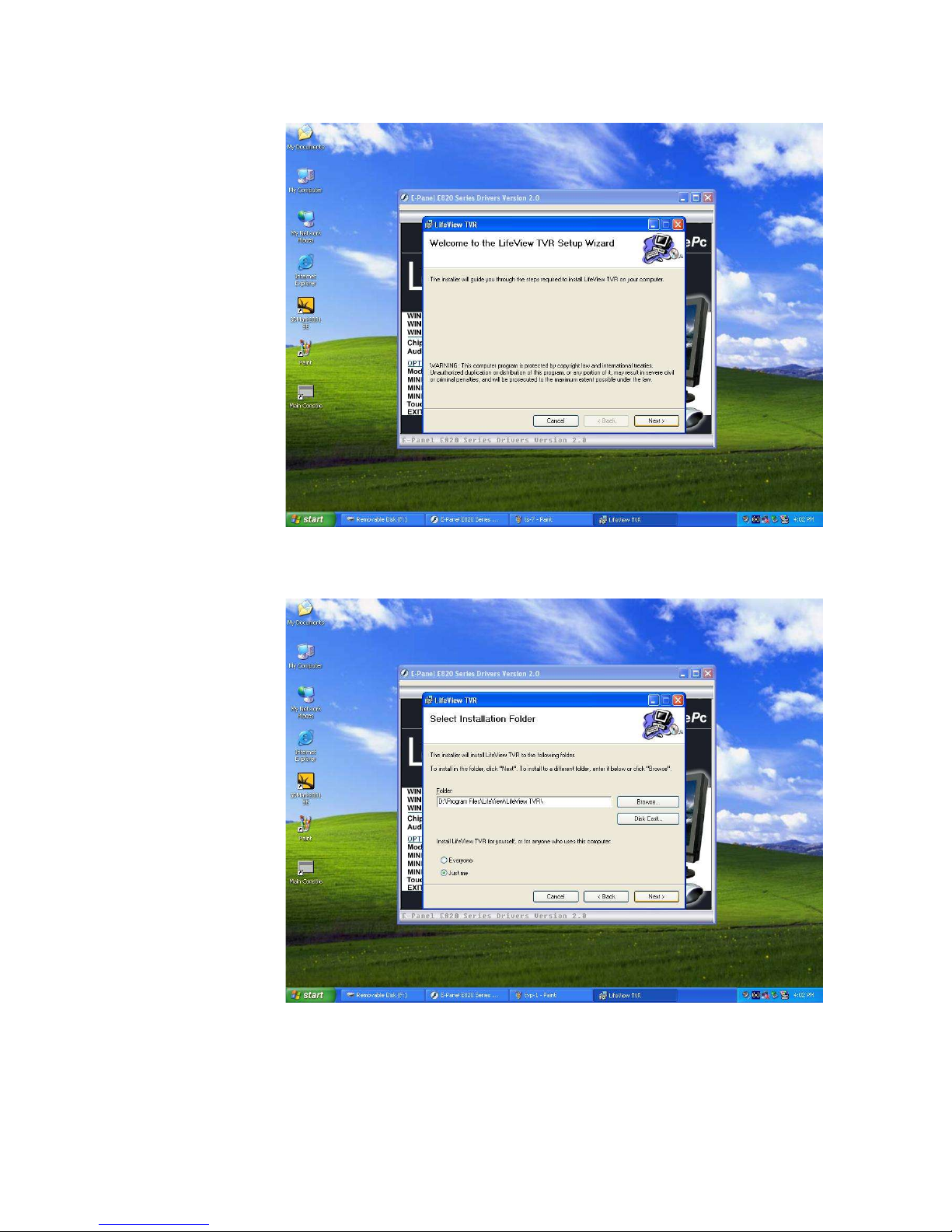
5.3.4.2
The program will guide you to complete the installation.
5.3.4.3
Follow the instruction to continue install until finish.
Page 24

5.3.5
5.3.5.1
TouchScreen Driver
To perform the Touch Screen Driver. Please click on “TouchScreen
Drivers”. Then a new setup screen come up. Choose the correct version of
Windows you installed. For this example, we click on “Install WinXP”.
Page 25

5.3.5.2
Follow the instructions to continue the installation.
Page 26

5.3.5.3
Choose the “Continue Anyway” when a pop-up window come up (shown
as below).
5.3.5.4
The installation completed. Don’t forget to calibrate the Touch Screen as
next step.
Page 27

5.3.5.5
After the installation completed. You need to calibrate the Touch Screen
before you use. Please double click “Main Console” icon on the desktop to
setup.
Click on “Create” in “MainConsole” Menu.
Page 28

5.3.5.6
Wait for a few seconds, the Main Console will show you the ID of Touch
Screen Controller. Please click on “Yes” to continue.
Page 29

5.3.5.7
The Touch Screen Controller added to Main Console after click on “Yes”.
Page 30

5.3.5.8
The installation completed. Now, you can setup the touch screen by
choosing the functions in Main Console.
5.3.5.9
Chapter 5: Removing and Replacing Parts
5.4
E-panel E820 LCD Computer is a fully equipped desktop. It integrates the LCD display
and all the other computer parts into the LCD case. Besides, most of the interfaces are
on the back of the computer base that makes the outline neat and fluid.
There are three components can be remove or replace by yourself. To remove or replace
those options in your E-820. You will need a Phillips Head Screwdriver.
Before you do the replacement. Please disconnect the DC power connector. Check the
parts and the configuration of your E-820 carefully. For more details, please refer to the
Installation Guide we provided.
Chapter 6: Take care of your E-820
6.
The installation completed.
This Chapter provides information to help you in the day-today use of your E-820.
Basics
6.1
Here are some basic points about keeping your computer functioning properly
.
Keep your E-820 in a clean, dry environment. Make sure it rests on a flat, sturdy
surface.
Do not cover any of the vents in the computer. These vents allow air flow to keep
your E-820 from overheating.
Keep food and drinks away from all parts of your E-820. Food particles and spills
might make the keyboard and mouse sticky and unusable.
Always disconnect the power cord by grasping the plug, not the cord.
Cleaning your E-Panel
6.2
Page 31

It is a good practice to clean your E-820 periodically to protect the surfaces and ensure
trouble-free operation. Be sure to turn off the E-820 before the cleaning.
Use only mild cleaning solutions and damp cloth to clean the painted surfaces of the
computer, LCD screen and keyboard.
Moving your E-820
6.3
Take the following precautions before moving your computer.
6.3.1
6.3.2
6.3.3
6.3.4
6.3.5
Back up all files and data from the hard disk.
Operating systems can vary in the way they perform backup procedures. See your
operating system documentation for information about software backup.
Remove all media, such as compact discs from the drives.
Shut down your operating system and turn off the computer and all attached
devices.
Unplug the power cord from electrical outlets, all attached cables and devices such
as USB devices, network cable, modem cable, audio devices etc. .
If you saved the original shipping cartons and packing materials, use them to pack
the units. If you are using different cartons, cushion the units to avoid damage.
7. Chapter 7: Troubleshooting
Computer problems can be caused by hardware, software or user error. You can use the
diagnostic aids discussed in this chapter to help you solve such problems yourself or gather
helpful information you can pass on to a service technician.
You can check the hardware by following the procedures in this chapter. If the hardware
checks out and you have not made a user error. You might have a software problem. If you
suspect that you have a software problem. See the operating system documentation and/or the
documentation supplied with the software.
Your computer performs the power-on self-test every time the PC is turned on. POST (Power
Page 32

On Self Test) tests the memory of the PC and reports the total memory installed. It also checks
the processor type and speed, the hard disk type and the CD-ROM type. Normally, POST runs
very quickly and do not see the results if no error in the self test. Otherwise, you will see the
error message of the device.
You can use the troubleshooting table below to find solutions to problems that have definite
symptoms.
Problem Description Solutions
General Power LED not light on
Power LED light on but
blank screen
Flashing cursor
Can not loading OS
continuously
Memory The amount of memory
displayed is incorrect
Ensure the power adapter’s AC and DC
connectors are securely connected to proper
connectors on the E-820
Contact your local technical support
If you have just added new software or a new
device. Try to remove it.
Be sure installed the correct type of DDR
memory and securely inserted in the socket.
In additional, this system features an
integrated video system in which some
memory is used by the video controller.
Windows will only report the memory
available for its use.
Page 33

Display Colour, Brightness or
Press the “Auto Adjust” button at the front
Contrast is incorrect
CD-ROM The indicator not lights
on when reading
The indicator lights but
can not read
Keyboard and
Mouse
All or some keys on the
keyboard do not work
panel.
You are not trying to run your monitor at a
higher refresh rate in Windows. See your
operating system documentation for
information about monitor refresh rate.
Pay attention any error on POST.
Check with the hardware configuration in
your operating system.
Be sure the CD seated correctly.
Check any damage, scratch or dust at the
back side of CD.
The keyboard cable is securely connected to
keyboard connector.
Clean up any dust, food or rubbish under the
Intermittent
Modem
Mouse do not work
Problem occurs only
occasionally
No response
key top.
The mouse cable is securely connected to
mouse connector.
Try to use the optical mouse in different
surface.
Be sure the fan grill is not blocked and is
working. The computer might overheat if
airflow is blocked or not working.
The modem cable is securely connected to
modem connector and your telephone socket.
Test the modem in Device Manager.
Page 34

USB Do not recognize
Try to unplug and plug in again or use other
Network
Microphone,
Earphone,
Internal
Speakers and
External
Speakers
devices
Do not connect
Not active
USB connectors.
Be sure the device driver installed.
In additional, Windows 98 use to install
drivers for USB
The network cable is securely connected to
network hub or switch properly. In additional,
pay attention on the indicator of hub or
switch light on or not.
Be sure the LAN driver installed.
Be sure the cables are securely connected and
in the correct connector.
Ensure the setting is correct in your
multimedia control software.
The power for external speakers switched on
when needed.
Technical Reference:
8.
Model E-panel 820 Series
Processor
Processor (CPU) Intel Pentium 4 / Celeron Process, Socket 478
Processor speed Up to 3.06GHz
Front side bus (FSB) 400 / 533MHz
Page 35

Main Board Chipset
Chipset Intel 845GL/V
System memory
Memory (RAM) std/max
RAM slots total
Module specifications
Memory speed
RAM type
Display
Screen type description
Simultaneous external display
Viewable image size (diagonal)
up to 1GB
1 DIMM
PC2700
333 / 400 MHz
DDR SDRAM
TFT
Yes
15 inches
Support colors
Maximum Resolution
Contrast Ratio
Typical white Luminance
Response Time
Hard drive
262,144 colours
1024x768
400:1 (Typ.)
250 nit
16ms (Typ.)
Page 36

Interface type Standard 3.5 inch Ultra-ATA 100/133
Storage support up to 250GB
Graphics
Description
Video RAM type
Max colors
Graphics type
Optical device
Optical device
Optical device speed
Communications
Intel Extreme Graphics 2
DVMT 2.0 allows up to 64MB of system memory
sharing
16777216 colours
2D/3D
Slim type CD-ROM, DVD, DVD COMBO or DVD+-
RW
48X Max
Ethernet description
Ethernet interface type
Wake on LAN capable
Fax/modem description
Fax/modem speed
Audio
Realtek 8100 10/100M
Ethernet-Integrated
Yes
56K V.93 designed modem
56Kbps data/14.4Kbps fax
Page 37

Description AC-97
Audio Output Internal: 2 x Internal 2W speaker
External: 5.1 speakers
Standard features
Keyboard
Mouse
Weight & dimensions
Weight
Height
Width
Depth
Expansion options
Expansion slot and type
E-Panel PS/2 107-key Keyboard
E-Panel PS/2 Optical Wheel Mouse
5.35kg
379.5 mm
353 mm
154 mm
1 x Mini PCI
Plug and play support
Serial Port Type
Parallel Port Type
Yes
2 Serial
1 Parallel
Page 38

Port connectors
6 x USB 2.0 ports
1 x RJ-11 Phone Connector
1 x RJ-45 Network Connector
1 x RS-232 serial port
2 x PS/2 Ports (Keyboard and Mouse)
1 x Mic In
1 x Earphone
1 x External Speakers
1 x TV antenna (Optional)
Power Adapter
Power Consumption 150W plus with ENERGY STAR the energy economizes
the standard
A/C Input Auto-switch 100-240V
DC Output 19VDC 7.9A
Optional
Touch Screen
Infrared port
Appendix
Notices
 Loading...