

Environmental Water Systems TT 1054 User Manual

EWS, Inc. / Environmental Water Systems
Care and Use Manual
Metered Sof tener Series
Information Provided for the Proper Set-Up, Installation and
St art-Up of the following Softeners:
Cabinet “all-in-one” Style:
RT 935 RT 1035
T win T ank (resin tank with separate brine t ank) Style:
TT 1054 TT 1354-11/2
4.3-1
ALL PRODUCT PROUDLY MANUFACTURED AND ASSEMBLED IN THE USA
To the Installer: Please Read and Leave this Owner’s Manual with the Unit or the Consumer
To the Consumer: Retain this Care & Use Manual for Product Registration and Future Reference
www.EWSWATER.com

4.3-2
EWS, Inc. / Environmental Water Systems
IMPORTANT GENERAL INFORMATION AND PRE-INSTALLATION CHECKLIST
FOR ALL EWS, INC./ENVIRONMENTAL WATER SYSTEMS
POINT OF ENTRY PRODUCT
Inspect and Verify: That all components are included with the unit and were not damaged in shipping. If there is obvious
damage to any equipment, it must be noted on the carrier’s Bill of Lading. Open and inspect the contents of all closed crates,
boxes or cartons, and inspect for concealed damage. The manufacturer is not liable for any damage during transit, as stated
and published in the conditions of sale, the receiving packing slip and accepted invoice. The manufacturer has made every
effort to ensure goods should be received in good condition and will support all legitimate claims against any carrier on behalf
of the receiving party . Please see reverse side of all receiving packing slips and yellow labels affixed to boxes for your rights.
Caution: Do not attempt to install any system using defective or damaged components. Do not install any system
that has been misapplied based assumed water conditions. Do not install any system that has been misapplied based on
usage, line service and/or the conditions and standards of operation stated below .
Warning: When drilling or cutting, use protective eyewear to prevent possible eye injury due to flying objects. When
using an open flame and/or hot materials, take the necessary precautions for you and the environment to prevent burns,
burning and/or fires.
CONDITIONS AND STANDARDS OF OPERATION
Water Conditions and Issues: Water must be potable and must be micro-biologically correct. Water must be of a known
quality or tested completely and independently to determine its quality , either municipally-treated or non-regulated, individual
or community , well water. Please see in this manual: Qualifications and Applications, St andard Industry T erms and the Limited
Warranty . Information provided for proper specifications are included in our published product manuals, and available through
customer service and on our website. A simple emphasis on, and test for , water hardness is inadequate. W ater issues with
iron and/or manganese require their removal by a separate filter unit installed ahead of any other unit.
W ater Pressure and Flow Rate: A minimum of 30 PSI (40 PSI for Iron units) and 8 GPM (12 GPM for 1354 Iron unit s)
is required for a backwash or regeneration valve to operate effectively . Water pressure not to exceed or to surge in excess of
a maximum of 75 PSI for the system. Unsure of pressure or it’s ability to surge? A pressure reducing valve (PRV) becomes an
insurance policy and is highly recommended for this and many other products that limit high pressure in your home. Excessive
pressure will void product warranty .
Water Temperature Range: Feed water temperature not to exceed 110°F or be allowed to go below 40°F. Protect unit
from exceeding high temperatures and never allow unit, its’ drain line and any water to freeze.
Electrical: An uninterrupted alternating current (A/C) supply is required for the operation of the control timer. Please make
sure your voltage supply is compatible with your unit before installation. Low 24 voltage step down transformer 120v , 50/60Hz
Existing Plumbing: Condition of existing plumbing and water heaters should be free from lime and iron buildup. Piping that
is built up heavily and clogged with lime and/or iron should be replaced. Old galvinized or combinations of plumbing materials
and their installation can cause separate water issues and conditions not related to water systems.
Location of Equipment: Units can be installed, almost anywhere. Inside or out side. V alves may be water resistant, not
water proof. Protect any system from the elements. Position equipment upright in its’ designated location, setting on a flat
surface. Level equipment as required. Equipment out of plumb can exhibit poor flow characteristics which will affect the
performance of the system.
Plumbing and Installation: Connect raw water supply to bypass inlet connection. Connect treated water bypass outlet
to home service line. Pipe sizes should be equal to or one size larger than the valve connection (3/4” line with 8 gpm to
standard 1” valving is acceptable). NO Torch, NO Heat - solder all piping as sub-assemblies before installing. Internal valve
damage can result from solder and/or torched heat
By-Pass V alves: All 1” noryl plastic valving are supplied with a 1” high flow dual-port bypass valve and male-threaded yoke
which are required for usage on these systems. On larger brass valves (1”HF , 1 1/2”, 2” and larger) the installation of a plumbed
bypass with 3 shut-off valves and unions is required, as specified per unit, in this service manual. The need for a proper bypass
is required by warranty and is necessary to isolate the system for maintenance and service.
Drain Connection: Drain line should be sized to handle maximum drain line flow rates for the system as designated on the
control valve. Minimum required drain line size at the valve (1/2” for all 1” valves, 3/4” for all 1 1/2” valves and larger). Recommended one pipe size larger for runs of 10 feet or more. A void overhead pipe runs, as undue backpressure can affect operation
of backwash/regeneration. See backwash (tank filtration systems) and regeneration (softeners) differences, capabilities and
restrictions - in drain connection procedures in those service manuals for those specific units.
ALL SPECIFICS TO EACH SYSTEMS’ SET-UP, INST ALL AND START -UP IS AV AILABLE IN THE SERVICE MANUAL.
WARNING: IMPROPER INSTALLATION AND/OR APPLICATION WILL
RESULT IN THE VOIDING OF ANY PRODUCT WARRANTY.
All plumbing should be done in accordance with all local plumbing codes.
www.EWSWATER.com

EWS, Inc. / Environmental Water Systems
4.3-3
INSTALLATION SUMMARY - SOFTENERS
Step 1: Locate the following:
Main Water Supply Line, Soft W ater Loop or Inlet to W ater Heater(s) (depending on application
or restrictions)
Drain Access, Electrical Outlet and Clearances.
Step 2: Check the incoming Water Pressure. Install a pressure regulator (PRV) if the water pressure
exceeds or can surge above 75 PSI.
Step 3: Place the tank where you want to install the unit, making sure the tank is level and on a firm base,
noting the clearances necessary to complete the installation.
Step 3A:
Warning: Do not exceed connecting distance determined by the length of 3/8” OD poly tube provided.
Step 3B:
Step 4: Install at barbed connection on brine tank side, min. 5/8” OD tubing (not supplied) to a suitable
Warning: This is a gravity fed tank drain, in any event that could cause an overflow of the brine t ank.
Step 5: T ighten the Valve on the T ank.
Caution: Since handling and moving the unit may loosen the valve head - Hand T ighten the V alve Head in a
Clockwise Direction. Make sure tank cover , if applicable does not interfere or cut into the connection.
Step 6: Identify Water Supply.
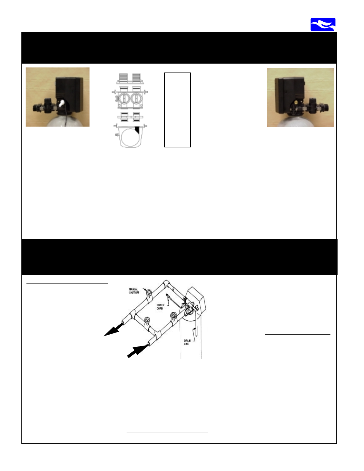
TT Units or “Twin Tank” style, place separate brine tank 6” from softener resin tank.
Connect the safety brine assembly found in the brine tank to the 3/8” plastic compression fitting,
then pass the tubing through the hole provided in the brine tank and connect to brass compres sion fitting on side of valve.
Cabinet Units “all-in-one” style softeners have the brine tank incorporated within the cabinet
along with the resin tank. The connection between the valve and the safety brine assembly has
been factory assembled.
drain.
Connect raw water supply to bypass inlet connection.
Connect treated water bypass outlet to home service line.
Units: RT935, RT1035 and TT1054 come with dual port bypass valve and male yoke
TT1354-1 1/2” needs the byp ass plumbed by the inst aller (see additional details)
Warning: Plumb the unit with the bypass and the male yoke included, or for larger brass valves, a byp ass
must be plumbed with 3 shut-off valves and unions. Do not cross-connect or plumb backwards.
UNTIL START-UP PROCEDURES - KEEP ALL VALVES TO/FROM SYSTEM CLOSED
Step 7: Connect a backwash drain line (1/2” or 3/4”) based on application and an air gap.
Warning: The performance of sof teners are dependent on the proper flow rates for regeneration discharge
FOLLOW START UP PROCEDURES BEFORE
LEAVING THE JOB
www.EWSWATER.com
4.3-4
EWS, Inc. / Environmental Water Systems
Set-Up and Installation for All 1” Valves:
RT 935, RT 1035, TT 1054
top view:
outlet
side:
to the
home
filtered
left
Outlet (filtered) Side:
left side view of valve and drain
port with included drain adaptor,
bypass and male yoke
back:
side:
supply
from
main
right
front:
inlet
Yoke
1” MNPT
Dual
Port
Bypass
O-Ring
Connect
Valve
Head
Must use dual-port, full
flow, noryl bypass with
1” MNPT yoke.
•Shuts off water to/from
the unit
•No additional plumbing
for media replacement or
maintenance
•Less costly plumbing
installation, easier startups, non-corrosive
Inlet (supply) Side:
right side view of valve and
brine line with included
bypass and male yoke
USING THE CONNECTED BYPASS VALVE AND 1” MALE NPT YOKE.
PLUMB INLET (supply) AND OUTLET (filtered) INTO THE UNIT.
•Follow the directional arrows molded onto the valve body and bypass. See pictures below for; top/front/back
and left/right views to prevent plumbing the unit backwards. Teflon tape is the only sealant to used on any of our
fittings. WARNING: No pipe dope.
•NO Heat, No Torch; Leave at least 12” between the male yoke and any solder joints. Failure to do this could
cause interior damage. Consider flexible stainless (1”FNPT x 1”FNPT (3/4” if your application) and at least 18”
in length) connected to copper male adapters, or some other applicable connection - no heat, saves time, neat
install, if applicable/code to your application.
WARNING: ONCE PLUMBED,
PROCEDURES.
DO NOT TURN ON WATER, UNTIL YOU BEGIN START-UP
Set-Up and Installation for 11/2” Valves:
TT 1354-11/2
Materials Needed for Installation:
11/2” pipe length to be
determined
3 - 11/2” Ball Valves
2 - 11/2” Unions
See Drain Requirements
DO NOT TURN ON W A TER,
OPEN ANY VALVES OR
PLUG IN THE ELECTRICAL
UNTIL YOU GO TO THE
START-UP PROCEDURES
Outlet (filtered)
Side
Back Side: Front Side:
Bypass
Valve
Inlet (supply) Side
Electric
Union
Union
11/2” 2850 Valve
Valve Cover: Black
NEMA 1 Rated
for resistence to
dust and moisture.
Drain
Hinged: left
Opens: from right
Controls: inside
PLUMB INLET (supply) AND OUTLET (filtered) INTO UNIT AND PLUMB BYPASS VALVE BETWEEN.
•Follow the directional arrows molded onto the valve body . See picture below for correct set-up.
•Use unions (a quick disconnect feature) at the inlet and outlet pipe, as pictured, to allow future servicing of
system without cutting and replumbing
•Use Ball V alves (preferred - easy to turn on/of f) at inlet/outlet pipes and bypass, as pictured for proper installation.
•NO Heat, No Torch; Leave at least 12” between the valve body and any solder joints. Solder joints prior to
connecting to valve body . Failure to do this could cause interior damage. Teflon tape is the only sealant to used
on any of our fittings.
WARNING: ONCE PLUMBED,
DO NOT TURN ON WATER, UNTIL YOU BEGIN START-UP
PROCEDURES.
Drain:
1” MNPT
Connected (included) to:
Brass Flow Control
Housing with 10 GPM
Flow Restrictor
1” FNPT x 3/4” FNPT
Materials Needed for Drain:
3/4” copper x male adapter
3/4” union
3/4” (min) drain line
length to be determined
www.EWSWATER.com
EWS, Inc. / Environmental Water Systems
4.3-5
Start-Up Procedure for All Units
The tank unit(s) have now been plumbed in with the inlet, outlet and drain
connections made in accordance with the manufacturer’s recommendations
and meets applicable plumbing codes.
Now, it is time to fill it with water, plug the unit in, and properly start it up by
following the start-up procedures below.
These units are similar to water heaters and other point of entry product. They
must be plumbed correctly and filled slowly while relieving pressure. These
units are also similar to other sink filtration product.
before beginning usage.
Making the connections, turning on the water and walking away is an
improper installation. Period.
Failure to start up unit properly may cause service issues, unhappy
consumers, and will void the warranty.
They must be flushed
STEP 1: FILL THE TANK WITH WATER - SLOWLY!
Units:
RT935, RT1035, TT1054
See Left Column
You Must Use:
Bypass and Male-Threaded Y oke Included
Units:
TT1354-1 1/2
See Right Column
You Must Plumb:
Inlet/Outlet and Bypass per Schematic
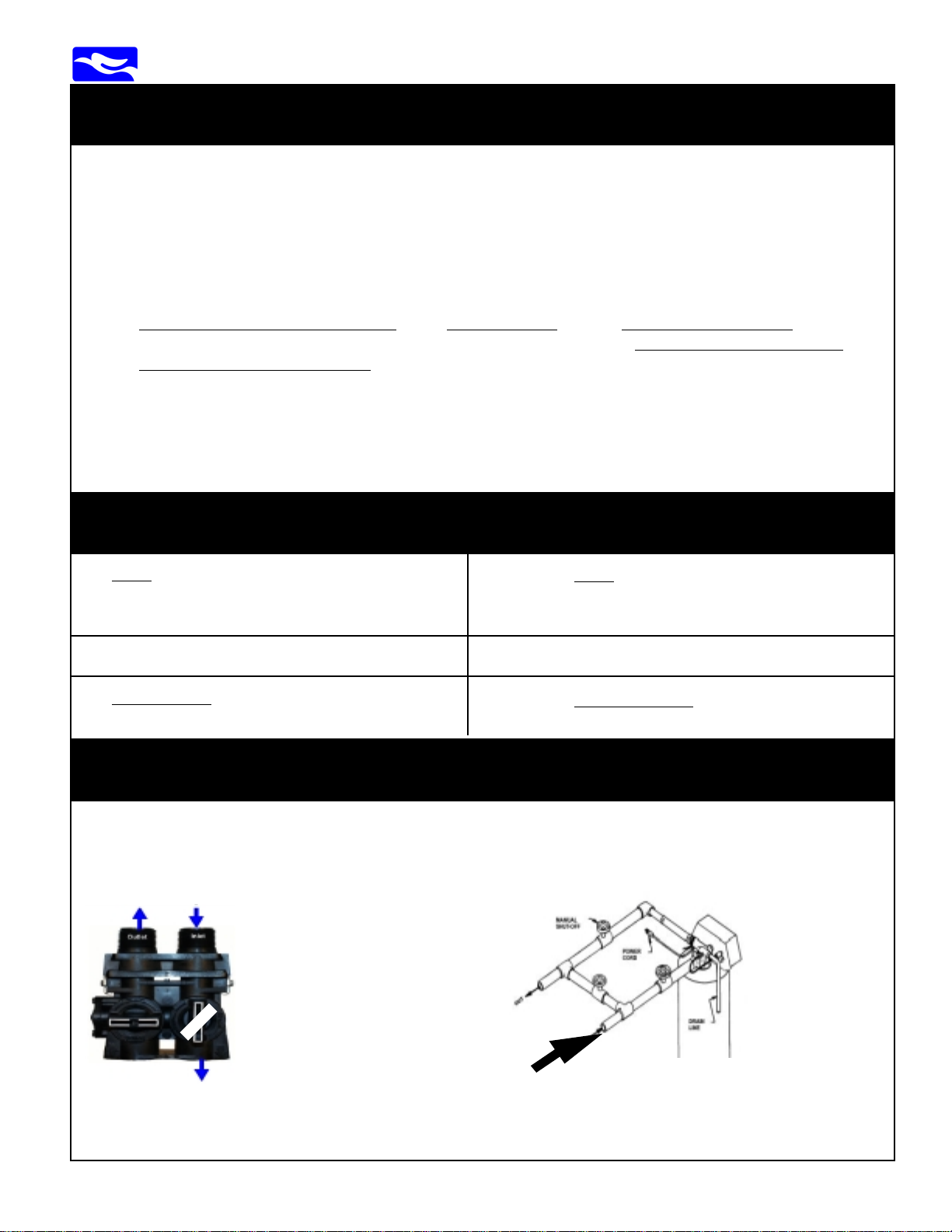
STEP 1-A: PARTIALLY OPEN INLET SIDE ONLY
Following a slow fill procedure will make the backwash and flushing steps easier and more effective.
P ARTIALL Y OPEN - 1/4 TURN (as
illustrated) on inlet supply side only
to fill tank slowly. Keep outlet side
closed
Inlet
Side:
P ARTIALLY OPEN -1/4 TURN with (preferred) Ball Valve or Slowly
and Partially Open Gate Valve on inlet supply side only to fill tank
slowly . Keep outlet side and bypass valves closed.
Open 1/4
turn only
to slowly
fill
Inlet Side Partially Open
Once the tank has been slowly filled, go to the next page. Follow the remaining simple procedures.
www.EWSWATER.com
4.3-6
EWS, Inc. / Environmental Water Systems
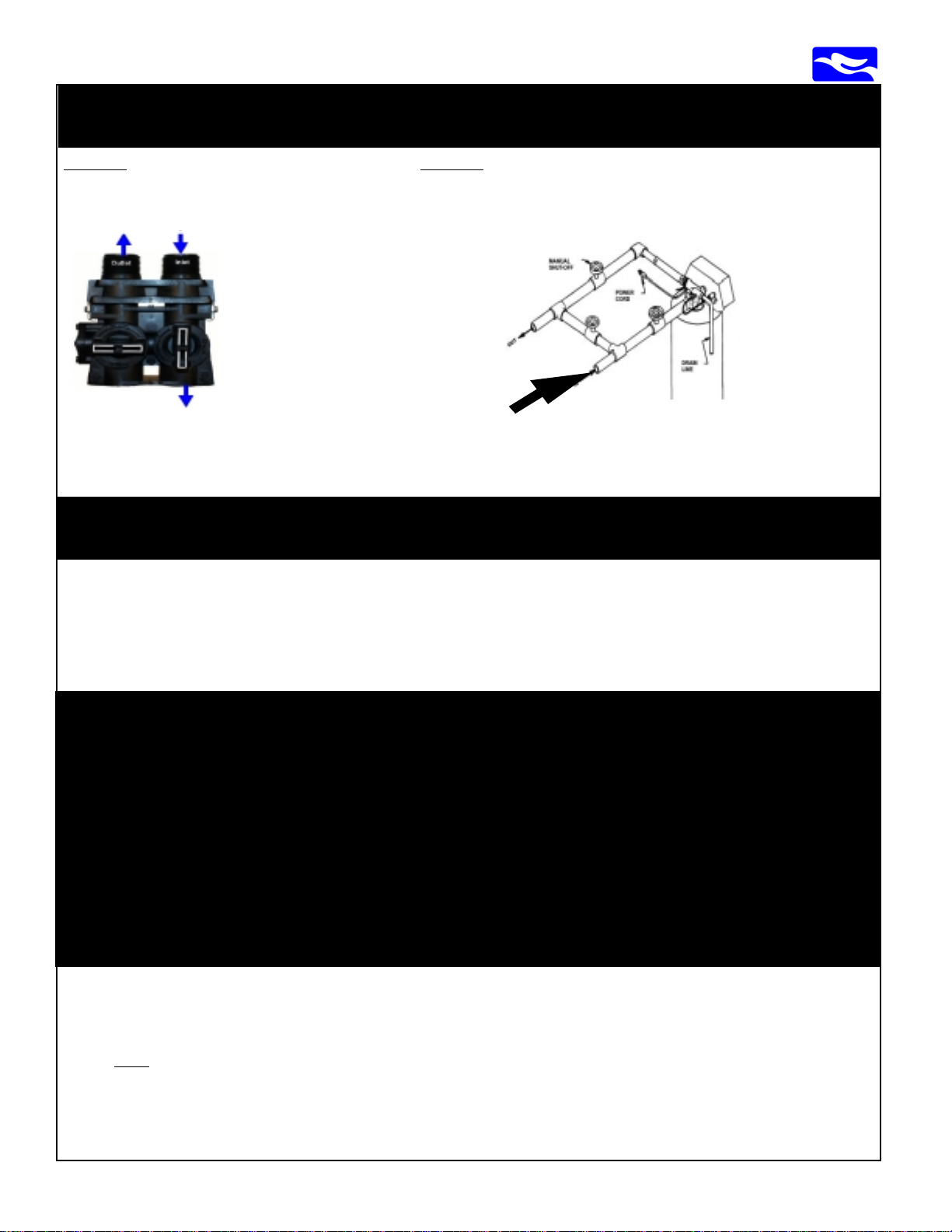
STEP 1-B: TANK IS FILLED, OPEN INLET COMPLETELY
SLOWLY OPEN - (as illustrated)
on inlet supply side only .
Keep outlet side closed.
Inlet
Side:
Open
Position
once filled
Tank is completely filled when sound of water stops or
at a slow pace of 1-2 GPM it will take 5-10 minutes. Keep outlet side closed until later.
SLOWLY OPEN -Completely open (preferred) Ball Valve or Gate
V alve on inlet supply side only .
Keep outlet side and bypass valves closed.
Inlet Side Open
STEP 2: PLUG IN THE ELECTRICAL
Plug the 24 volt transformer into any unswitched electrical outlet or an acceptable extension to that outlet. Be sure that if
plugged into a GFI outlet that the outlet has been reset. Please inform the consumer of the need for an unswitched outlet
which can not be turned off and that GFI outlets need to be occassionally checked for operation. Please follow all applicable
local codes. If using an extension, make sure of a complete and secure connection. No spliced connections. Do not break
into wires with fasteners or staples. Make sure transformer has a snug and secure connection to outlet (larger units must use
set screws to secure transformer to outlet). Electrical is used to bring power to the digital valve, in order to keep the time and
operate the automatic backwash program. Cost of this operation is similar to the cost of a radio alarm clock.
STEP 3:
BEGIN THE REGENERATION CYCLE STEPS AS
FOLLOWS FOR START-UP
THESE STEPS ARE CRITICAL FOR THESE
HIGHLY EFFICIENT METERED VALVES
PLEASE FOLLOW THE STEP BY STEP
INSTRUCTIONS
Address Advancement Note:
Push and Hold Extra Cycle Button for approximately 5 seconds to advance the valve into Regeneration
Cycles. As each Regeneration Cycle is Entered a Red Dot will Illuminate on the lef t of the Regeneration
Cycle Title printed on the face panel.
To advance to the next Regeneration Cycle before it times out, Push the Extra Cycle Button once (Do Not
Hold) once the Number on the left of the Address Display stop s flashing.
www.EWSWATER.com
 Loading...