

Page 1
EWS, Inc. / Environmental Water Systems
Care and Use Manual
Reverse Osmosis Systems
Information Provided for the Proper Set-Up, Installation and
Start-Up of the following Filtration Systems
Three-Stage Reverse Osmosis Units:
RU300C18, RU300C18w/UV
Four-Stage Reverse Osmosis Units:
RU400T35, RU400T35w/UV
Five-Stage Reverse Osmosis Units:
RU500T35, RU500T35w/UV ,
RU500T35w/BP , RU500T35w/UVw/BP
4.2-1
ALL PRODUCT PROUDLY MANUFACTURED AND ASSEMBLED IN THE USA
To the Consumer:
Retain this Care & Use Manual for Maintenance and Information
You Must Register this Product - It is a Requirement for Warranty
www.EWSWATER.com office: 702-256-8182 (m-f; 8:30-4:30, pst) fax: 702-256-3744 [email protected]
Page 2

4.2-2
EWS, Inc. / Environmental Water Systems
A Special Message to Our Customers,
EWS, Inc. and Environmental Water Systems would like to thank you for your consideration in selecting from our
comprehensive list of residential filtration and conditioning product.
We recommend that you take the time to read the information that pertains to your product as you begin to use it.
The information in this manual is designed to assist your installer to set-up, install and start-up your system properly.
In addition, the information contained in this manual is designed to provide the consumer, the most comprehensive
information on this series of product.
Please contact us if you have any questions, comments or additions to the information provided.
Sincerely,
Customer Service at EWS, Inc.
EWS, Inc. and Environmental Water Systems
9101 W. Sahara A ve., Suite 105-J8
Las Vegas, NV. 891 1 7
Office: 702-256-8182 Available Monday through Friday , 8:30 - 4:30 Pacific S tandard Time
Fax: 702-256-3744 Dedicated and A vailable 24/7
E-Mail: [email protected]
Web Site: www .ewswater .com
Installation of the Filtration System - Please Read the Enclosed Information
Please take the time to familiarize yourself with the unit you are about to install. The Table of Content s will point to
specific instructions for the simple step-by-step instructions for;
Installation of a Dispenser/Faucet
Placement or Locating the Water System
Inlet Supply Water Connection
Connection of Tubing from Supply and to Dispenser/Faucet
System St art-Up and Operation Procedures
You may need the following for proper installation:
• Teflon tape • Work Gloves • Safely Glasses • Knife or scissors
• Adjustable Wrench • Pliers • Screwdriver; straight & phillips • Drill & drill bits
WARNING: V erify that all components are included with the unit and were not lost, misplaced, or damaged in shipping
or handling. Any damage in shipping needs to be reported to the shipping company.
WARNING: Do not attempt to install this system using defective or damaged components. Check and inspect, inlet and
outlet fittings and any other connections on this system that might have been damaged during shipping and handling. Check
all these components again upon installation and start-up for any hidden issues. All plumbing should be done in accordance
with all local plumbing codes. Water Pressure: minimum 40psi, maximum 65p si. Water Temperature Range (cold supply
only): not to exceed 95°F or below 40°F. Electrical (if applicable): an uninterrupted a/c supply, (if applicable): make sure
voltage supply is compatible with your unit prior to install
WARRANTY: Warranty Registration of this product is required to have a warranty. A proper inst allation and start-up will
save you time, money and hassles, and is also required for warranty purposes. Any issue as a result of improper application,
set-up, installation and/or start-up will void any warranty .
www.EWSWATER.com office: 702-256-8182 (m-f; 8:30-4:30, pst) fax: 702-256-3744 [email protected]
Page 3
EWS, Inc. / Environmental Water Systems
Table of Contents
INST ALLATION SUMMARY AND INDEX
OF YOUR REVERSE OSMOSIS SYSTEM
Dispenser/Faucet Q & A 4
Placement or Locating the Dispenser/Faucet 5
Installation of the Supplied Dispenser/Faucet
Dispenser/Faucet with Air Gap 6
Dispenser/Faucet without Air Gap 7
Inlet Supply Water Connection
Basic Supplied Connection 8
Preferred Connection for All Applications 9
Placement or Locating the System 10
Placement or Locating the Storage Tank 11
Drain Installation and Connection 12
4.2-3
Connection of Tubing for Reverse Osmosis Systems 13-14
System Start-Up and Operation Procedures 15-16
HOW TO MAINTAIN YOUR SYSTEM
Replacement of UV Lamp (if applicable) 17
Replacement of Filter Cartridges 18
Replacement of Membranes 19
Cleaning of Empty Housings, RSR Control Valve, Booster Pump (if applicable) 20
GENERAL INFORMATION
Water Fitration Systems Included in this Care and Use Manual 22-23
FILTER REPLACEMENTS AND ORDERING
Filter, Membrane and UV Lamp Replacement s 24
Ordering Filters, Membranes, UV Lamp Replacements, and Parts 25
Maintenance Guide 26
Trouble Shooting Guide 27-32
Schematics 33-35
Warranty 36-37
Terms and Conditions of Sale 38
www.EWSWATER.com office: 702-256-8182 (m-f; 8:30-4:30, pst) fax: 702-256-3744 [email protected]
Page 4

4.2-4
EWS, Inc. / Environmental Water Systems
Dispenser/Faucet Q & A - Reverse Osmosis
Spout pulls out from faucet body that’s why it swivels. Spout has 2 o-rings at base and is inserted completely
into bottom of body to prevent leaking. Handle and tip can also be removed
Q: I do not want to drill any extra holes or use a separate dispenser/faucet - what can I do?
A: Nothing. Reverse osmosis systems are limited to a separate dispenser.
WARNING: These systems manufacture a limited amount of water and therefore the connection to the
cold side of your sink faucet is an unavailable option. In addition, the water produced by a
reverse osmosis system is aggressive and would have adverse leaching effects on any
other metals (ie: brass, copper) other than stainless steel.
Note: Drinking water filtration systems are pass through systems and will allow this option. There
will be a diminishment in your flow rate to the cold side of the faucet (kitchen faucet has a
flow rate of up to 2.3 gallons per minute and the filtered water is delivered up to 1 gallon per
minute). To get filtered water you must be sure you have the faucet to the cold side only.
This application or option is not applicable for reverse osmosis systems.
Q: I would like to use another dispenser/faucet?
A: Based on many styles and finishes, a consumer may have another dispenser they would like to use.
No problem, all these items have universal or industry standard fittings, or if not, can be easily adapted to fit.
Always check with manufacturer for proper specifications.
Note: EWS, Inc. includes a standard chrome, long-reach, lead-free faucet with white tip, handle and
optional air gap adaptor . Be aware - an air gap may be code and required with a dispenser/
faucet installation.
Options: EWS provides the following options to match other items at an additional charge;
Change your white tip and handle to black
Change your white air gap adaptor to black
Change your faucet to the following finshes; white faucet (with white tip, handle and air gap),
satin nickel, polished nickel, polished brass, or oil rubbed bronze (all with black tip, handle and
air gap). Inquire with your local EWS, Inc. distributor, cont act an authorized internet distributor
or visit us on the web (see page 4.2-25 for more details).
Q: Can we connect the filtered water up to other devices?
A: Yes, simply connect by a “T” connection, the filtered water line to any instant hot, chiller, ice-maker,
refrigerator, etc. Regarding flow rate, be mindful of too many (3 or more) connections. Also, any length of total
tubing in excess of 20 feet combined to tank, faucet, and all items may create issues with delivery rates**.
See our Point of Entry , Whole Home Appliances to filter all the fixtures within the home.
WARNING: Reverse osmosis may have warranty or restrictions with other devices, consult with other
manufacturer’s product information.
Note: **Tubing in excess of 20 feet is calculated by adding the length of tube from unit to tank
(yellow tubing) and the faucet outlet on unit to dispenser or other device (blue tubing). EWS,
Inc. supplies 5 feet of each type of tubing.
Q: Do I need to use the air gap adaptor?
A: Y es, if local code requires that an air gap be used. Since the unit is both connected to a pot able water
supply and a drain, some code requires an air gap to prevent cross-contamination, similar to all
EWS point of entry systems, a dishwaher and/or washer machines. Care has to be taken with this
unit to make all the proper connections. Follow all local plumbing codes.
www.EWSWATER.com office: 702-256-8182 (m-f; 8:30-4:30, pst) fax: 702-256-3744 [email protected]
Page 5
EWS, Inc. / Environmental Water Systems
4.2-5
Placement or Locating Dispenser/Faucet - Reverse Osmosis
Step by step instructions to mount and secure the supplied dispenser/faucet
Professional Installation is Strongly Recommended
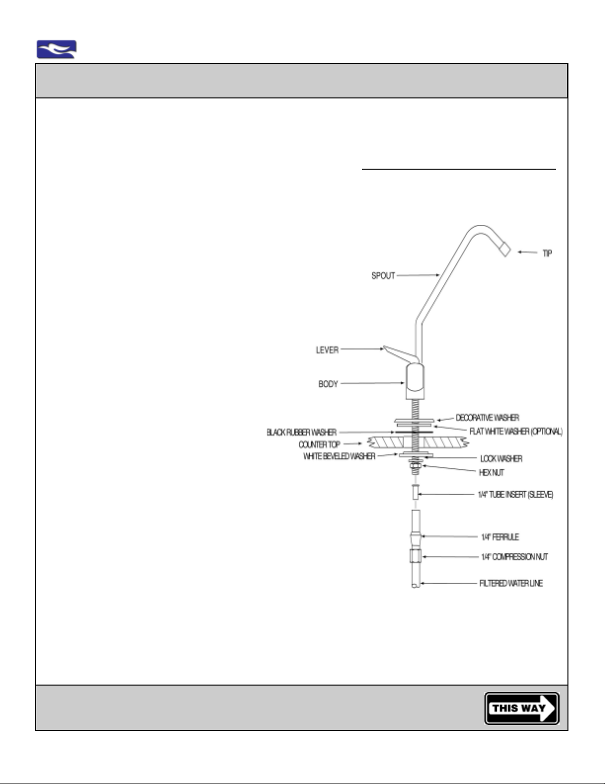
Step 1: Locate Faucet Parts Bag
Parts Included: faucet body with handle, faucet spout with tip, decorative washer, black rubber
washer, white beveled washer, lock washer, hex nut, 1/4” tube insert sleeve,
1/4” plastic compression ferrule, 1/4” compression nut
Included flat white washer (for use under decorative washer depending on hole/application)
Optional Parts: air gap adaptor (white) for use with RO air gap applications
Preferred - Select a standard sink location to mount the faucet.
It is recommended that the faucet be placed in a hole provided on most sinks similar to the ones used for a
sprayer, soap dispenser and/or dishwasher air gap. If the hole or sp ace is unavailable, an alternative location
will be required: NON-AIR GAP: MINIMUM HOLE REQUIRED 1/2”, MAXIMUM 1 3/8”
AIR GAP: MINIMUM HOLE REQUIRED 1 1/4”, MAXIMUM 1 3/8”
Option A: On the sink. This option is to drill a new hole into the sink rim itself, if space allows.
Option B: On the countertop next to a sink. This option is to position the faucet spout in the
correct location to drain into the sink. This requires a clearance around the faucet
both above and below the countertop. Use the supplied dispenser as a template or
see the enclosed dispenser schematic and dispenser dimensions.
Prepare to drill the hole using the dispenser as a template.
• Sinks can be made of, but not limited to, stainless steel, copper, porcelain/steel, enamel/cast iron,
man-made surfaces, stone, concrete, and/or materials known or unknown at this time.
• Countertops can be made of, but not limited to, or be a combination of, natural stone, enamel,
porcelain, concrete, wood, metals and/or man-made materials known or unknown at this time.
CAUTION: Please consult with the sink or countertop manufacture, supplier, fabricator, or
installer for proper drilling techniques and methods.
EXTREME CARE MUST BE T AKEN IN DRILLING THE HOLE FOR ANY SURF ACE. THE SURFACE MA TERIALS OF SINKS AND COUNTERTOPS CAN CHIP OR CRACK. THE MANUFACTURER ASSUMES NO
RESPONSIBILITY FOR ANY DAMAGE RESUL TING FROM THIS INST ALLA TION.
WARNING: USE SAFETY GLASSES OR OTHER EYE PROTECTION WHEN GRINDING OR
DRILLING TO PREVENT POSSIBLE EYE INJURY DUE T O FL YING PARTICLES.
Follow Steps 2 through 12
Installation of the Supplied Dispenser/Faucet
www.EWSWATER.com office: 702-256-8182 (m-f; 8:30-4:30, pst) fax: 702-256-3744 [email protected]
Page 6
4.2-6
EWS, Inc. / Environmental Water Systems
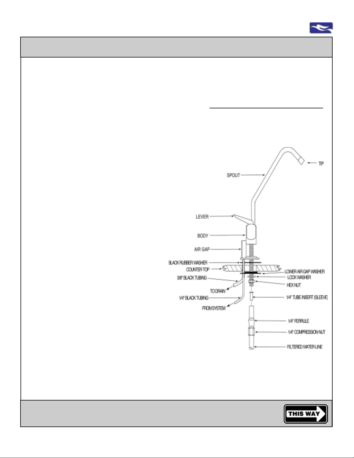
Installation of the Supplied Dispenser/Faucet with Air Gap
Step by step instructions to mount and secure the supplied dispenser/faucet
If using another faucet, please review the instructions included with that product**
***Other Air Gap connections can be found with
Drain Installation and Connection and System Interconnection instructions
Above the Surface
Step 2:
Place air gap to bottom of faucet body***
(optional: place flat white washer under decorative washer)
Step 3:
Place black rubber washer below air gap
(or below optional flat white washer)
Step 4:
Place faucet stem through hole and center
Below the Surface
Step 5:
Insert white beveled washer, bevel side up to
fit snugly into a (1 3/8”) pre-drilled hole or flat side
up depending on the application
Step 6:
Place lock washer on this white beveled washer
Step 7:
Spin hex nut onto faucet stem and
tighten hex nut and washers into place
Step 8:
Slide 1/4” compression nut (threads up)
onto 1/4” filtered line
Step 9:
Slide 1/4” plastic compression ferrule, long side
down onto filtered water tube. Ferrule will seat into
compression nut
Step 10:
Insert 1/4” tube insert sleeve into 1/4” filtered water line
Step 11:
Insert 1/4” blue (filtered water) tube into faucet stem. Leave
other end available for system interconnection
Step 12:
Thread 1/4” compression nut onto faucet stem and tighten
Enclosed Dispenser/Faucet Dimensions***
Height: from deck to top of dispenser 8”
from deck to tip of dispenser 6 1/4”
Reach: from center of dispenser to tip 6”
Hole: minimum required with air gap 1 1/4”
maximum 1 3/8”
CAUTION: Do not overtigthen fittings
Note: Spout pulls out from faucet body and has 2 o-rings at base. Insert completely into bottom of faucet body to prevent
leaking. Spount swivels to direct water. Handle and tip can be removed. Handle can be locked up in open position.
** Other faucets check with specifications. ***All dimensions are approximate.
Go to the Inlet Supply Water Connection
www.EWSWATER.com office: 702-256-8182 (m-f; 8:30-4:30, pst) fax: 702-256-3744 [email protected]
Page 7
EWS, Inc. / Environmental Water Systems
4.2-7
Installation of the Supplied Dispenser/Faucet without Air Gap
Step by step instructions to mount and secure the supplied dispenser/faucet
If using another faucet, please review the instructions included with that product**
Above the Surface
Step 2:
Place decorative washer to bottom of faucet body
(optional: place flat white washer under decorative washer)
Step 3:
Place black rubber washer below decorative washer
(or below optional flat white washer)
Step 4:
Place faucet stem through hole and center
Below the Surface
Step 5:
Insert white beveled washer, bevel side up to
fit snugly into a (1 3/8”) pre-drilled hole or flat side
up depending on the application
Step 6:
Place lock washer on this white beveled washer
Step 7:
Spin hex nut onto faucet stem and
tighten hex nut and washers into place
Step 8:
Slide 1/4” compression nut (threads up)
onto 1/4” filtered line
Step 9:
Slide 1/4” plastic compression ferrule, long side
down onto filtered water tube. Ferrule will seat into
compression nut
Step 10:
Insert 1/4” tube insert sleeve into 1/4” filtered water line
Step 11:
Insert 1/4” blue (filtered water) tube into faucet stem. Leave
other end available for system interconnection
Step 12:
Thread 1/4” compression nut onto faucet stem and tighten
Enclosed Dispenser/Faucet Dimensions***
Height: from deck to top of dispenser 8”
from deck to tip of dispenser 6 1/4”
Reach: from center of dispenser to tip 6”
Hole: minimum required 1/2”
maximum 1 3/8”
CAUTION: Do not overtigthen fittings
Note: Spout pulls out from faucet body and has 2 o-rings at base. Insert completely into bottom of faucet body to prevent
leaking. Spount swivels to direct water. Handle and tip can be removed. Handle can be locked up in open position.
** Other faucets check with specifications. ***All dimensions are approximate.
Go to the Inlet Supply Water Connection
www.EWSWATER.com office: 702-256-8182 (m-f; 8:30-4:30, pst) fax: 702-256-3744 [email protected]
Page 8
4.2-8
EWS, Inc. / Environmental Water Systems
Basic Inlet Supply Water Connection **
Professional Installation Using a Preferred Connection is Strongly Recommended
**This unit is supplied with a saddle tapping valve and should be considered a basic connection for copper , steel or brass
3/8” to 1/2” O.D. pipe prior to the angle stop shut-off of the cold water line to the kitchen faucet. This should be considered
a “do-it-yourself” connection which is not applicable in many situations and may not meet local codes.
A qualified plumber should choose to make the inlet supply water connection by a more preferred method.
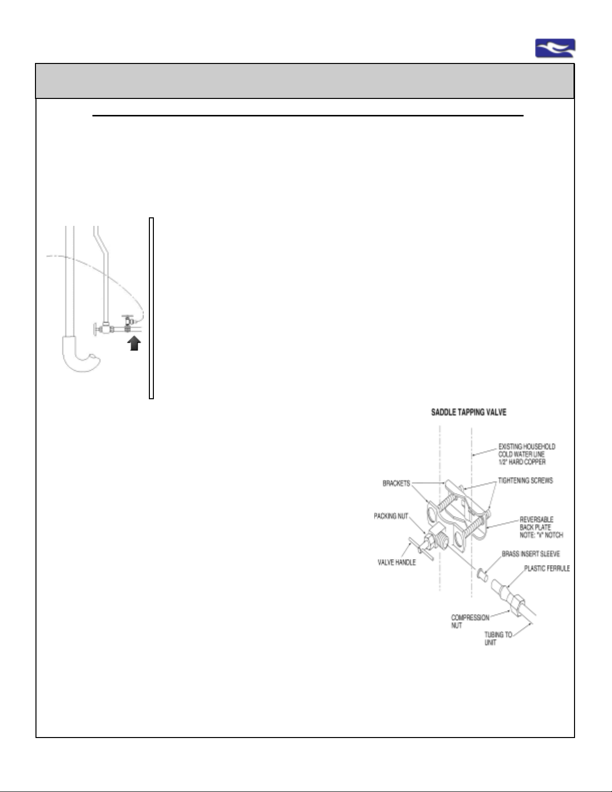
Instructions from the bag containing the supplied saddle tapping valve, if applicable
Step 1: From parts bag locate: saddle tapping valve and 4’ of 1/4” tubing, color coded: red or orange (supply line to unit).
wall
angle
stop
cold
supply
to
kitchen
faucet
saddle
tapping
valve
pipe for
install
and
clearance
from wall
supply
tube
to
filtration
unit
drain
and
trap
Step 4: Loosely assemble saddle tapping valve on pipe
A: For all 3/8 O.D. pipe, use side of bracket with side projections
toward or against pipe to prevent distortion of tubing.
B: For all 1/2 O.D. pipe, use “V” side of bracket with that notch
toward or against pipe.
Step 5: T ighten screws evenly . Make sure brackets are parallel,
then tighten firmly until the valve is not moving on the pipe.
CAUTION: Do not over tighten fittings.
Step 6: Connect the 1/4” plastic tubing to the saddle tapping
valve by following these instructions:
A: Slide 1/4” compression nut over plastic tubing with threads toward the
saddle tapping valve.
B: Slide 1/4” plastic ferrule over plastic tubing with long tapered side
toward saddle tapping valve.
C: Place 1/4” brass insert sleeve into the end of the 1/4” orange/red
plastic tubing.
D: Insert orange/red tubing into saddle tapping valve. Leave other end
available for system interconnection
E: Tighten compression nut onto saddle tapping valve.
Step 7: Be sure the packing nut is tight, then turn the handle of the saddle tapping valve clockwise
until it is firmly seated. NOTE: For Copper Pipe - the pipe is now pierced.
HINT: Back the end of the piercing lance out, turning the handle counter-clockwise. Then re-insert by turning the handle
of the saddle tapping valve clockwise until it is again firmly seated. This will clear any possible debris that can
block piercing lance and water flow.
Step 8: Turn the handle counter-clockwise to open the valve for water supply . Keep main line shut of f and proceed with
the remainder of the installation and start-up.
Step 2: Locate cold water line that feeds your existing faucet. Determine if there is enough
space to install the saddle tapping valve on the hard line between the wall and the angle
stop.
CAUTION: USE ONL Y COLD WATER LINE. NOT INTENDED FOR SUPPLY BY HOT
WATER.
Step 3: Shut off the main water supply to the house and open the faucet to relieve water
pressure in the hard pipe. NOTE: Shutting the angle stop only , still leaves water in that pipe.
Shut the main supply .
CAUTION: Do not turn valve handle before or while installing the “saddle tapping valve”.
Make sure the piercing lance does not protrude beyond the rubber gasket. Failure to do this
may result in damage to the piercing needle.
NOTE: For Copper Pipe - go directly to #4.
For Steel or Brass Pipe - follow A, B, C below, then go to #4
A: Drill a 3/16” hole in pipe. Use a hand drill to avoid shock hazard.
B: Turn handle to expose lance beyond the rubber gasket no more than 3/16”.
C: Place body of valve over hole so the lance fits into the hole
CAUTION:
Do not over
tighten fittings.
www.EWSWATER.com office: 702-256-8182 (m-f; 8:30-4:30, pst) fax: 702-256-3744 [email protected]
Page 9
EWS, Inc. / Environmental Water Systems
Preferred Inlet Supply Water Connection - All Applications
Professional Installation Using a Preferred Connection is Strongly Recommended
A qualified plumber should choose to connect the inlet supply water supply by a more preferred connection. ***
The Preferred Inlet Supply Water Connection is Applicable in All Applications and Codes
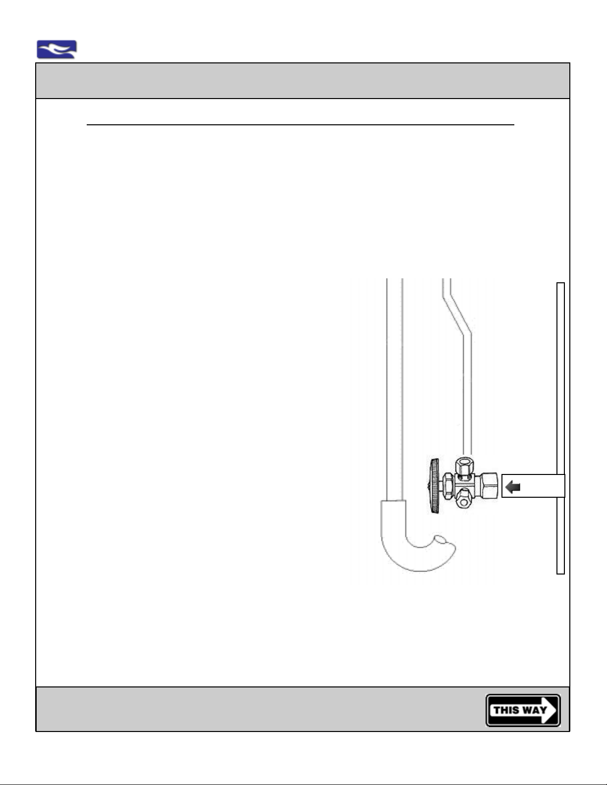
Replace the Angle Stop with a Proper 3-Way Fitting:
There are a number of options to properly install any one of these drinking water filtration systems.
Identify the cold water supply line and then you will need to know;
• Size or O.D. diameter of pipe or tubing
• Pipe material (hard or sof t copper, steel, brass, stainless, PVC, plastic, etc...)
• The existing angle stop or fitting will assist in determining the proper 3-way angle stop or fitting needed for
your specific application
4.2-9
A more preferred method to connect the inlet supply line is to shut off
the water main and replace the entire angle stop. This will have a connection from the house main water line, a connection to the cold water
side to the kitchen sink faucet and a much better connection for the
inlet supply to the filtration unit. This will provide one fitting with a shut
off to the kitchen faucet and a shut off to the filtration system. The
replacement of the angle stop is a better plumbing connection and any
number of fittings can be used for the correct application under any
circumstances.
Examples of common connections and fittings available:
• OPTIONS:
1/2” IPS x 3/8” compression x 1/4” compression
3-way angle stop
• OPTIONS:
1/2” compression x 3/8” compression x 1/4” compression
3-way angle stop
Note:
Be sure one outlet is 1/4” compression
for the water filter 1/4” inlet/supply tubing
drain
and
trap
Example:
new 3-way
angle stop or
fitting
shut
off
cold water
supply pipe
to kitchen
faucet
kitchen faucet supply
connection
main water
1/4” filtration
unit supply
connection
supply pipe
wall
water flow
Proper installation is dependent on your specific application and the concept of proper installation is universal.
Locate the supply , shut off your main water supply , install the proper connections
and follow the remaining instructions in this manual.
***EWS, Inc. can not anticipate all the different locations, applications and materials used by your builder and/
or plumbing contractor regarding your household or sink piping, therefore we offer a generic and common fitting
with proper instructions. A qualified plumber , plumbing supply location, or hardware store will have no problem
with alternative parts and advice necessary to install your unit.
Go to the Placement or Locating the System
www.EWSWATER.com office: 702-256-8182 (m-f; 8:30-4:30, pst) fax: 702-256-3744 [email protected]
Page 10
4.2-10
EWS, Inc. / Environmental Water Systems
Placement or Locating the Reverse Osmosis System
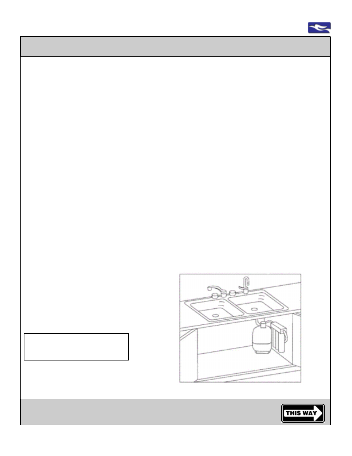
Simply place the water system on a level floor, cabinet bottom or horizontal surface.
Always assume for enough space for the system and the storage tank, and tubing to remove, move
and/or adjust for filter and membrane replacement and maintenance.
If mounting the system to a wall, cabinet side or other vertical surface,
Please see the following;
Step 1: All filter cartridges and membranes for system are preinstalled. If the unit is installed in a
permanent hanging position, a minimum clearance of 2” will be required to allow filter
replacement.
Step 2: Mark pilot holes using the bracket as a template.
Step 3: Using a drill bit or punch, drill a hole or punch as a starter hole to catch the mounting screws.
WARNING: AL TERNA TIVE F ASTENING METHOD MAY BE REQUIRED FOR PLASTER BOARD,
P ARTICLE BOARD OR SIMILAR MA TERIAL INST ALLA TION. USE SAFETY GLASSES
OR OTHER EYE PROTECTION TOPREVENT POSSIBLE EYE INJURY DUE TO
FL YING P ARTICLES.
Step 4: Set mounting screws (provided) with screw driver. Leave a 1/4” gap between the screw
head and mounting surface to allow the bracket to slide on easily .
Step 5: Slide the bracket over the screws and hang the unit. Make sure unit is level.
Now make the connections of tubing to/from the system.
WARNING: UPON INST ALLA TION AN R.O. SYSTEM MA Y HA VE TO BE “BURPED” OF ANY AIR IN
THE LINES. UPON COMPLETION OF THE “SYSTEM ST AR T -UP AND OPERATION
PROCEDURES”, REVIEW THIS WARNING AND DIRECTIONS ON PAGE 4.2-16.
Note: The interconnection between the inlet, outlet, drain and tank lines can cause air in the unit at the
RSR control valve. Air in lines, and at this valve, will not allow R.O. to function properly.
Helpful Hint:
Find the enclosed Spanner Wrench
Kitchen Faucet
Dispenser/Faucet
of filtered water
that came with the unit and place it
on top of the bracket.
When finished, roll up this Service
Guide and place on top with wrench.
T ake a note of the Model # and
WQA Serial # for the required
warranty registration of this unit.
This Service Guide and the wrench
Stored Filtered
before going to
Dispenser/Faucet
Note:
Water flows
from Tank
through
Postfilter(s)
for use
Storage Tank on floor
Unit Mounted to Wall (option shown)
or Placed on level floor
Inlet from Cold
Inlet/Supply
Connection
(angle stop
not shown)
will come in very handy when it’s
time for filter replacement.
strictly for illustration purposes only
Go to the Placement or Locating the Storage Tank
www.EWSWATER.com office: 702-256-8182 (m-f; 8:30-4:30, pst) fax: 702-256-3744 [email protected]
Page 11
EWS, Inc. / Environmental Water Systems
4.2-11
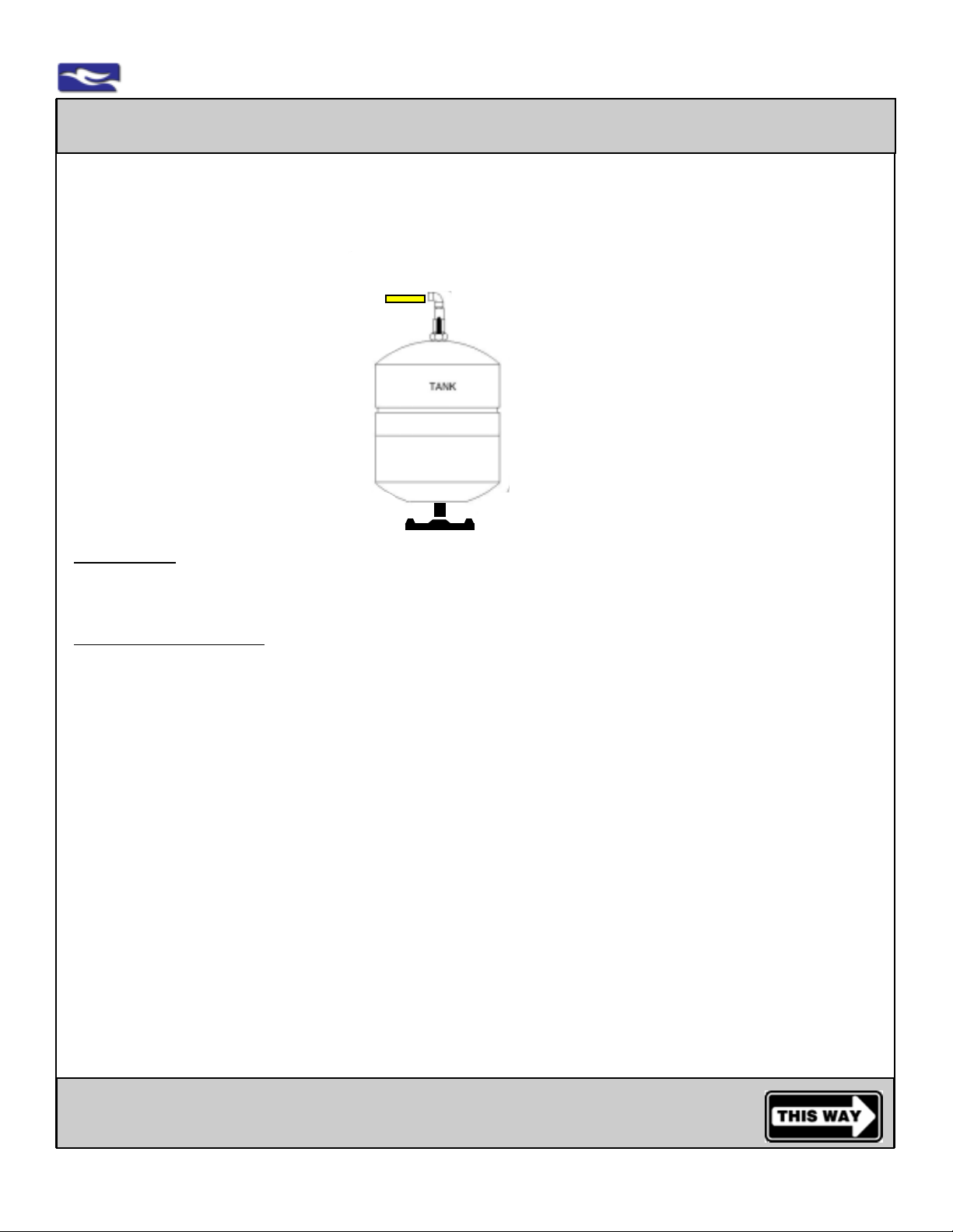
Placement or Locating the Storage Tank
Open the box containing the storage tank and plastic base.
Place storage tank on the plastic base near the system and allow for room for connections.
Locate the Tank Valve in the parts box
Tank Valve
1/4” yellow tubing
into
quick connect fitting
valve handle to open or close tank
1/4” male threads at tank top
Air Pressure Valve
at tank bottom
Storage Tank:
The storage tank holds up to 3.2 gallons of product water . A bladder within the t ank keeps water under pressure and away from bare metal. The tank has an air pre-charge of 5-7 psi (without water) from the factory.
Storage Tank Preparation: Locate the following:
plastic tank stand, tank valve, 1/4” male threads at top of tank, and the air pressure valve at bottom of tank
T ank stand
strictly for illustration purposes only
Step 1: Air pressure valve seats into tank stand when tank is in upright position. Place tank on stand.
Note: Tank may be placed on its side, if necessary. Use tank st and to prevent rolling.
Step 2: Using Teflon tape (not included) wrap 1/4” male threads on storage tank using clockwise
motion for at least three revolutions.
Step 3: Install tank valve on storage tank. Do this by hand tightening valve clockwise onto male
threads of the storage tank. There is no need to overtigthen
KEEP TANK VALVE CLOSED.
DO NOT OPEN TO ANY WATER UNTIL INSTRUCTED TO DO SO.
Closed Valve 90º angle to the yellow tubing and connection
Open V alve In line/parallel with yellow tubing and connection
WARNING ABOUT TANK PRESSURE:
USE ACCURATE (0-20) GAUGE FOR LOWER READINGS TO MEASURE. IF NEEDED TO ADJUST, EMPTY
TANK, USE A SIMPLE BICYCLE OR SPORT BALL PUMP ONLY. DO NOT OVER-INFLATE TANK
PRESSURE.The tank should be 5-7 psi without water for proper operation. Pressure variances due to higher
elevations may occur. Under or over-inflation will prevent proper operation of system.
Go to Drain Installation and Connection
www.EWSWATER.com office: 702-256-8182 (m-f; 8:30-4:30, pst) fax: 702-256-3744 [email protected]
Page 12
4.2-12
EWS, Inc. / Environmental Water Systems
Drain Installation and Connection
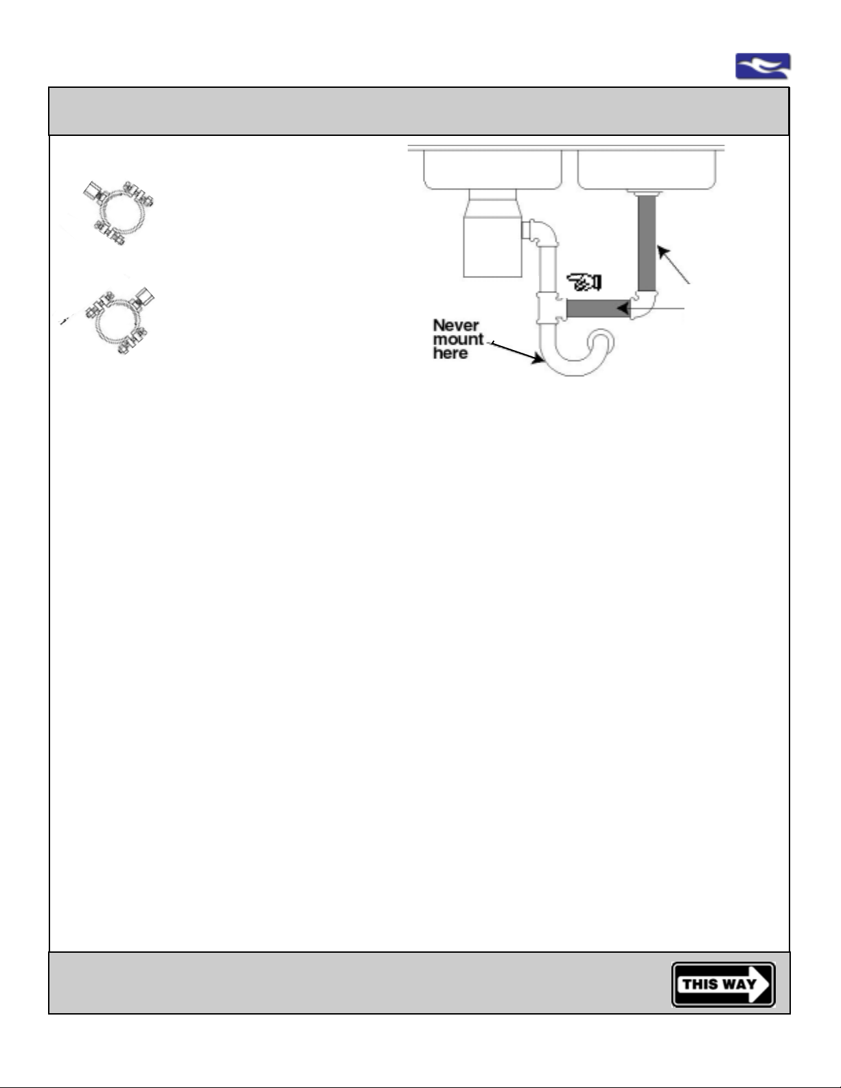
WARNING:
Never mount off the garbage
disposal drain pipes.
When installing drain saddle on a
Illustration
A
Step 1: From the parts bag locate:
horizontal pipe - install connection
at the 10 o’clock or 2 o’clock
position (as illustrated to the left)
This allows for the proper flow of
RO rejection water and will help to
prevent any cross-contamination
Drain saddle assembly and the 1/4” x quick connect fitting that is needed for the application
For use with a non-air gap installation: use (smaller) 1/4” quick connect fitting x 1/4” mpt
For use with an air gap installation: use (larger) 3/8” quick connect fitting x 1/4” mpt
sink #1 sink #2
Mount
drain saddle
here when
disposal
using only
one (1) sink
trap
strictly for illustration purposes only
Mount
drain saddle
at either
location
(shown in dark)
when using
two (2) sinks
Step 2: Place the drain saddle but do not tighten.
Placement of drain saddle should be located on the vertical tail piece of the plumbing system
at least 2” above the horizontal outlet or trap assembly .
NOTE: On the vertical pipe: The higher the placement on this pipe, the greater the chance of
increased noise in your waste line. Drain connection should be pointing out or towards you
as you look into the cabinet.
On the horizontal pipe as an alternate location: See illustration A, the drain saddle should be
at a 10 o’clock or 2 o’clock position
Step 3: Once the drain saddle is placed, use a 1/4” drill bit, and drill a hole slightly above the drain
saddle. Do not drill through the other side of the pipe.
Make sure the one hole is complete with clean edges and clear of debris.
WARNING: IF DRILLING MET AL PIPE, PROTECT YOURSELF FROM SERIOUS INJURY OR F A T AL
SHOCK, USE A HAND DRILL OR A CORDLESS DRILL T O MAKE THE HOLE. IF YOU USE
AN ELECTRIC DRILL, OUTLET MUST BE GROUNDED. USE SAFETY GLASSES OR OTHER
EYE PROTECTION WHEN GRINDING TO PREVENT POSSIBLE EYE INJUR Y DUE T O FL Y ING P ARTICLES.
Step 4: Loosen drain saddle and slide over the 1/4” hole. Make sure the hole in the drain pipe is
aligned with the hole in the drain saddle. Tighten drain saddle using a screwdriver, alternating
sides for even tightening.
Step 5: Using Teflon tape (not included) wrap 1/4” male threads on 1/4” x quick connect fitting
(selected for air gap or non-air gap application) using clockwise motion for at least three
revolutions. Hand tighten fitting clockwise into drain saddle.There is no need to overtigthen.
Go to the Connections of Tubing
www.EWSWATER.com office: 702-256-8182 (m-f; 8:30-4:30, pst) fax: 702-256-3744 [email protected]
Page 13
EWS, Inc. / Environmental Water Systems
4.2-13
Connection of Tubing for Reverse Osmosis Systems
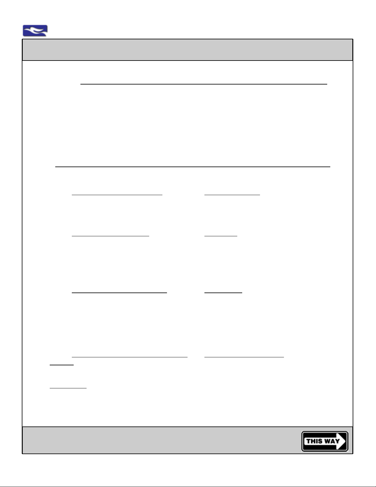
Step 1: Before Making the Connections - Remove Colored Vinyl Plugs Correctly
This system may have come with sample plugs. Please remove before installation.
WARNING: NEVER A TTEMPT TO REMOVE TUBING OR SAMPLE PLUGS BY JUST PULLING.
Follow simple instructions illustrated below to remove properly.
INSPECT: Inspect the fitting for any damage from shipping, handling and/or delivery . STOP, if collet
is damaged in any way; call, fax or e-mail customer service for a replacement fitting.
Step 2: Making the Connections from Inlet/Supply to Unit,
Faucet/Dispenser to Unit, Unit to T ank, and Unit to Drain
FOLLOW INSTRUCTIONS AND ILLUSTRATIONS FOR PROPER TUBING CONNECTIONS
DO NOT TURN ON ANY WATER TO UNIT UNTIL INSTRUCTED TO DO SO.
Step 2a: Inlet/Supply Connection to Unit: Orange/Red tubing
Connect the installed orange/red tubing from the installed Inlet/Supply Connection to the location
of the unit labeled “FEED”. This is the raw supply water into the system.
• For all 3-& 4-Stage Units, “FEED” is into the “Pre-Filter” housing on the bracket
• For all 5-Stage Units, “FEED” is into the “Sediment” housing on the bracket
Step 2b:
Step 2c:
Step 2d:
Air Gap: Connect the black 1/4” tubing from the location on the unit labeled “DRAIN” to the 1/4”
Non Air Gap: Connect the black 1/4” tubing from location on the unit labeled “DRAIN” to the 1/4”
• For all Units, “DRAIN” is located behind the membrane housing at the back/top of the bracket at the
RSR control valve (this valve has 5 other installed connections). The “DRAIN” fitting may have an
inserted black sample tube
Faucet Connection to Unit: Blue tubing
Connect the installed blue tubing from the installed dispenser/faucet to the location on the unit
labeled “FAUCET”. This is the filtered water from the system.
• For all 3-Stage Units, “FAUCET” comes from the “Postfilter” housing on the bracket
• For all 4-Stage Units, “FAUCET” comes from single quick connect fitting on the In-Line
“Postfilter” on top of the unit
• For all 5-Stage Units, “FAUCET” comes from the “Postfilter” housing on the bracket
Unit Connection to Storage Tank: Yellow tubing
Connect the yellow tubing from the location on the unit labeled “TANK” to the installed Tank
Valve on Storage Tank. The fitting on the unit will always be a 3-way, swivel “T” quick connect
fitting and may have an inserted sample yellow tube (remove sample).
• For all 3-Stage Units, “TANK” is located at 3-way, swivel “T” quick connect fitting at the back
of the bracket behind “Postfilter” housing
• For all 4-& 5-Stage Units, “TANK” is located at 3-way, swivel “T” quick connect fitting on the
In-Line “Postfilter” on top of the unit
Unit Connection to Drain Connection(s): Black tubing (1/4” and 3/8”)
barb on the air gap adaptor. Then, connect the black 3/8” tube from the 3/8” barb on
the air gap adaptor to the 3/8” quick connect fitting installed on the drain saddle.
quick connect fitting installed on the drain saddle.
See the Connection of T ubing Illustrated
www.EWSWATER.com office: 702-256-8182 (m-f; 8:30-4:30, pst) fax: 702-256-3744 [email protected]
Page 14
4.2-14
EWS, Inc. / Environmental Water Systems
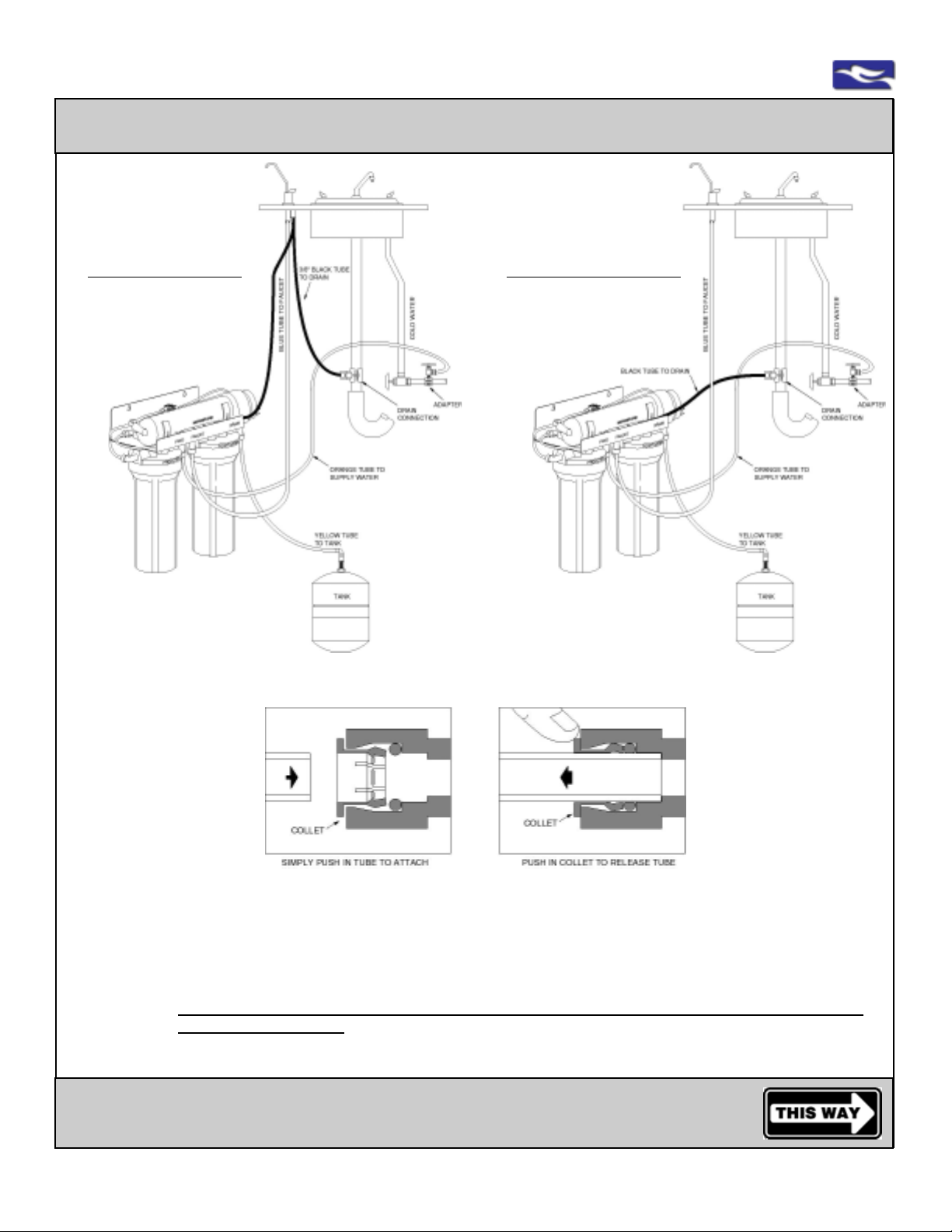
Connection of Tubing Illustrated
Air Gap use:
1/4”MPT x 3/8” quick connect
fitting connected to drain saddle
Air Gap Tubing Connections:
1/4” black tubing from unit to
1/4” barb at air gap adaptor
3/8” black tubing from 3/8” barb
at air gap adaptor to
1/4”MPT x 3/8” quick connect fitting
at drain saddle
Air Gap
Installation and the
5 connections
Note: 4-& 5-Stage RO Units and those with UV and pump options may have slightly different connection configurations.
Non-Air Gap use:
1/4”MPT x 1/4” quick connect
fitting connected to drain saddle
Non-Air Gap Tubing Connection:
1/4” black tubing from unit to
1/4”MPT x 1/4” quick connect fitting
at drain saddle
Non- Air Gap
Installation and the
4 connections
strictly for illustration purposes only: RU300C18 shown
Follow Connection of Tubing Instructions, labeling and/or sample tubing.
Never Pull Tube Out T o
Remove
Push Collet In To
Release
T o Insert, Press Tubing In
Firmly and Completely
To Test Integrity of Fitting,
Give a Gentle “Tug” To
Insure Proper Connection
See All
Cautions, Warnings and
Inspections
CAUTION: Always leave the tubing provided to allow lifting the unit for filter replacement and maintenance. Make sure
tubing has gentle curves. Roll and secure as needed. Do not bend or kink tubing. We do not recommend
shortening the tubing, however, If needed, at end, cut tube straight and do not flatten. A void any tubing
contact to hot water lines.
WARNING: NEVER A TTEMPT TO REMOVE TUBING BY JUST PULLING.
Follow simple instructions illustrated above to remove properly .
INSPECT: Upon installation, inspect the connection and give the tubing a gentle “tug” to insure proper connection
and integrity of the fitting.
Inspect the fitting for any damage from shipping, handling, delivery , and/or installation.
STOP, if collet is damaged in any way; call, fax or e-mail customer service for a replacement fitting.
Go to the System St art-Up and Operation Procedures
www.EWSWATER.com office: 702-256-8182 (m-f; 8:30-4:30, pst) fax: 702-256-3744 [email protected]
Page 15
EWS, Inc. / Environmental Water Systems
4.2-15
System St art-Up and Operation Procedures
Reverse Osmosis Systems have specific issues with air in system, proper pressure in tank,
the proper draining of reject water, and proper connection between various components.
Follow these procedures for new installations and all filter/membrane replacements.
A proper start-up insures the system is without issues.
If anything is discovered, this is the time to discover it and correct any problems or
questions that arise. Lack of a proper start-up will void the warranty.
Only For Units with Electrical Connection: Units with UV Option and/or Booster Pump Option
Step 1A: Connect UV lamp cord and plug in transformer unit to typical 110v electric outlet.
Step 1B: Connect Booster Pump cords and plug in transformer unit to typical 110v electric outlet.
NOTE: Electrical outlet must be dedicated and unswitched. Be aware of any GFI outlets and
the need to reset. Surge supression highly recommended.
For All Units:
Step 2: Close inlet water supply to thesystem.
Turn off water supply to other devices that may be connected to this unit.
Step 3: Close storage tank valve. Storage tank valve should be closed. Tank valve handle is
perpendicular or at a 90º angle to the yellow tubing connected into the tank valve.
Step 4: Pull up and lock dispenser/faucet handle in open position (if using another type of
dispenser - put into open position).
Step 5: Turn on any main water supply which was shut off earlier (usually for new install).
Open inlet water supply to the system.
NOTE: Initially you may observe a sputtering. It may take up to 10-15 minutes for water to begin
to drip from dispenser/faucet.
Step 6: Once a steady drip is available (drips about a gallon of water per 1-11/2 hours),
Close the dispenser/faucet
Step 7: Open storage tank valve, so that tank valve handle is parallel or inline with the yellow
tubing connected into the tank valve.
Step 8: Allow system to fill the tank twice and drain both tanks of water produced before
actual use**. This will wash carbon fines, membrane preservatives, and air*** from the
system. This process may take in excess of 10 hours.
NOTE: This correct procedure of “fill then empty, fill then empty, and final fill” may be a full day
or an overnight procedure. This is the proper way this type of system is started up.
Continue with the proper start-up of the reverse osmosis system
System St art-Up and Operation Procedures - Continued
www.EWSWATER.com office: 702-256-8182 (m-f; 8:30-4:30, pst) fax: 702-256-3744 [email protected]
Page 16
4.2-16
EWS, Inc. / Environmental Water Systems
System Start-Up and Operation Procedures - Continued
Continue with the proper start-up of the reverse osmosis system
Step 9: Allow system to fill (this may take up 7 hours) and use as normal. If applicable, only
open water supply to other devices connected to this unit after storage tank is filled.
Step 10: Inspect for leaks at all connections, fittings and/or housings. If a problem exists,
please shut off water supply to the system and consider the following solutions;
• Plumbing connections at the inlet/supply connection, saddle tapping valve, or angle stop.
Please review all plumbing procedures and correct.
• Plumbing connections to dispenser/faucet and any other fixtures or cross-connections.
Please review and correct.
• Inspect for leaks at all unit connections such as connections between housings, the
membrane &/or cartridge housings. Report any issues for assistence or needed part(s).
• Inspect for leaks at all tubing connections and the labeled “Feed” and “Faucet” connections
between the supplied tubing and the quick connect fittings. To insure proper connection,
give a light “tug” (not a hard pull) on tubing to check the grip on all fittings.
**CAUTION: Do not drink water from system until start-up procedures have been completed and system has
been flushed properly. Improper start-up may result in poor performance of the system. Proper
procedure will rinse and purge system. Do not make water available to any ice-makers,
rerigerators or any other devices until the system is completely flushed.
***WARNING: UPON INST ALLATION OR FIL TER/MEMBRANE REPLACEMENT AN R.O. SYSTEM MA Y HA VE T O
BE “BURPED” OF ANY AIR IN THE LINES.
YOU MA Y HA VE T O FOLLOW THIS PROCEDURE TO FINALIZE THE INST ALLATION:
CLOSE THE TANK VALVE (See page 4.2-11), CLOSE (if applicable) WATER SUPPLY TO OTHER DEVICES
CONNECTED TO THIS UNIT, OPEN AND LOCK DISPENSER (observe sputtering from dispenser or a slow drip),
THEN ROT ATE THE UNIT 90 DEGREES CLOCKWISE AND HOLD IN VERTICAL POSITION, AFTER A MINUTE
RETURN UNIT BACK TO HORIZINTAL POSITION, THEN ROT A TE THE UNIT 90 DEGREES COUNTERCLOCKWISE AND HOLD IN THAT VERTICAL POSITION. AFTER 1 MINUTE, RETURN UNIT BACK TO HORIZONTAL
POSITION. WATER SHOULD DRIP AT A STEADY FLOW (about 1-11/2 gallons per hour) WITHOUT SPUTTERING OR ANY GURGING SOUND. REPEA T AS NEEDED. THEN CLOSE DISPENSER, OPEN T ANK V AL VE, OPEN
(if applicable) WATER SUPPLY TO OTHER DEVICES.
NOTE: Cloudy Water - If you draw your water into a glass and it appears to be cloudy, it’s only air and
nothing bad. Let the glass sit and watch the air rise and dissipate. The filter cartridges used
are full bed depth. The carbon (GAC) cartridges have a great deal of surface area. It may take
24-48 hours for this to correct itself after you have filled and emptied the tank 2 times.
If any damage was identified in shipping or handling. You’ll need to make a claim with the shipper, as indicated on our
Packing Materials, our Packing Slip and the published General Terms and Standard Conditions of Sale.
If you have identified a problem, please contact our offices. The Best Way; go to www.ewswater.com, click button “Contact
Us” and click link to “Customer Service and Help”, fill out the form and help will be on the way. Let us know if we can offer
advice on a plumbing issue that may not be related to the actual unit, or a question or issue that may be unit related. If in
need of a part under warranty we can readily send it. Parts (original only) needed out of warranty can be obtained through
your contractor, local distribution or at www.waterontheweb.com.
WARNING: Maximum pressure is 65 PSI. Pressure unregulated can surge or exceed the maximum rating on this and
many items in the home. High pressure creates a water hammer or banging pipes. It’s also the reason to use stainless
hoses for washer machine connections and not the rubber. A pressure reducing valve (PRV) at your main water service line
(if not code) is greatly recommended by many manufacturers’ of many different household items, plumbing products and
appliances and must be checked annually. A point of use (sink location) pressure limiting valve is also available.
www.EWSWATER.com office: 702-256-8182 (m-f; 8:30-4:30, pst) fax: 702-256-3744 [email protected]
Page 17
EWS, Inc. / Environmental Water Systems
Register this Product - It is a Requirement for Warranty
Familiarize yourself with the system,
its’ replacement filters and maintenance.
To Register, take note of the Model # and WQA Serial # found on the unit’s
bracket,
Understand your system’s capabilities, put the enclosed Spanner Wrench
and this Service Guide on top of the unit bracket,
See your options in water treatment, for you , your family and your home
by EWS, Inc.
Register Your System
our confidential data base will remind you to replace your filters, use our
enclosed form which you can fax or mail to our offices, or register on-line
at ww.ewswater.com, click the “PRODUCT REGISTRATION” button, then
the link for “Online Interactive Registration”
4.2-17
Replacement of UV Lamp (if applicable)
UV Lamp should be changed annually based on tested results to maintain UV effectiveness.
NOTE: Electrical outlet must be dedicated and unswitched. Be aware of any GFI outlets and the need to reset. Surge
supression highly recommended. Not responsible for bulb that may expire prior to annual service.
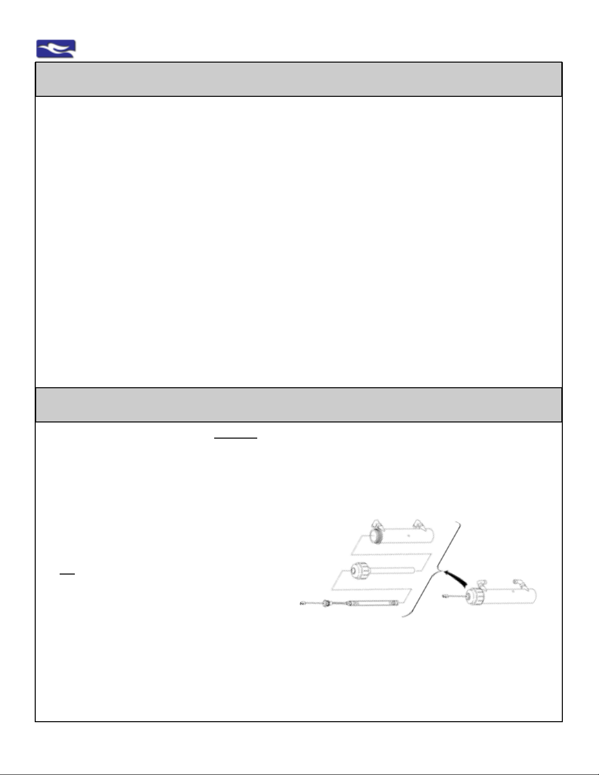
Step 1:
Unplug the transformer. Then disconnect the UV lamp cord.
NOTE: All R.O. Units with UV Option:
UV module is set on top of bracket (easy access)
Step 2:
Pull firmly on the UV lamp tail only to remove the lamp.
Do Not remove cap at top of UV Module
(If needed, snap the UV module from the bracket clips to
gain access for lamp removal).
Step 3:
Insert and firmly press new UV lamp into the top of the cap.
(If applicable, snap the UV module back into the bracket clips).
Step 4:
Reconnect UV lamp cord. Plug in unit transformer.
WARNING: DO NOT DISCONNECT UV MODULE FROM THE F ACTOR Y CONNECTIONS AND DO NOT OPEN
UV CAP FROM UV MODULE FOR TYPICAL UV LAMP REPLACEMENT.
4
2
3
strictly for illustration purposes only
1
1 - Fully Assembled UV Module
2 - UV Module Housing
3 - UV Cap with Quartz Glass Sleeve
4 - UV Lamp with Lamp Cord
www.EWSWATER.com office: 702-256-8182 (m-f; 8:30-4:30, pst) fax: 702-256-3744 [email protected]
Page 18
4.2-18
EWS, Inc. / Environmental Water Systems
Replacement of Filter Cartridges - All RO Units
It is recommended that all filters be changed at least annually or more frequently based on usage and
local water conditions. The quantity and quality of the water processed effects the life of the filters.
Step 1:
Open dispenser/faucet. Lock handle in the up and open position and allow water to flow.
Water will eventually only drip then almost come to a stop.
Now go to Step 2. Keep dispenser/faucet open until instructed to close.
Step 2:
When water has come to a stop or very slow drip, Close inlet water supply to the system.
Step 3:
Using your spanner wrench, turn housing (which contains the filter cartridge)
counterclockwise to loosen. Remove housing.
Step 4:
Remove filter and dispose.
NOTE:
See optional disinfection procedure of empty unit on page 4.1-20 before replacing any filters,
membranes, or UV lamp (if applicable)
Step 5:
Insert new filter(s), replace and tighten housing by turning clockwise.
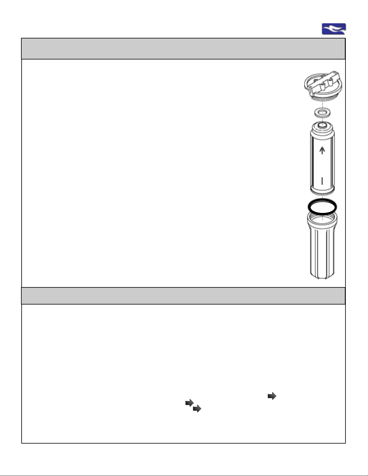
CAUTION:
The GAC Postfilters (UDF10HP on all RO Units, OCB on 5-S t age RO only) has a gasket
that must be at the top of the filter to be replaced correctly . All other filters do not have a
top or bottom and can be inserted either way .
CAUTION:
Inspect O-Ring for housing base. Make sure it is clean, free of any debris and not
damaged or kinked. Make sure it is correctly seated into the channel inside the housing
before replacement.
Step 6:
ONCE NEW FIL TERS/MEMBRANE HAVE BEEN REPLACED - CHECK AND FOLLOW ALL
APPROPRIA TE STEPS FOR “SYSTEM START -UP AND OPERA TION PROCEDURES”
CAUTION:
WA TER WILL BE PRESENT WHEN FIL TERS ARE CHANGED.
A p an, towel, etc. should be placed under the housings to catch any water .
strictly for illustration purposes only
Upper
Housing
to Bracket
GAC
Filters
“UDF10HP”
& “OCB”
Gasket
Must
Face Up
all other
cartridges
can go in
either
direction
Housing
O-Ring
Housing to
be removed
Replacement of In-Line Postfilter - 4&5 Stage Units Only
NOTE: In-Line filters are labelled as a “Postfilter” on top of all 4-& 5-St age Units. The filter is a self-contained cartridge.
Replacements do not come with fittings. Follow instructions for the removal and replacement of these cartridges.
Step 1: Identify the end of the filter cartridge with the swivel “T” connection with two (2) tubes.
Y ellow tube is always straight in. White tube is always at the bottom of the “T”.
Step 2: Disconnect the white tube and the yellow tube. Disconnect fitting from the filter cartridge
by turning counter-clockwise. Keep for re-connection.
Step 3: Identify the end of the filter cartridge with the connection with one (1) tubing fitting:
Step 4: Disconnect the blue (4-Stage Units) tube or white (5-S tage Unit s) tube. Disconnect fitting
from thefilter cartridge by turning counter-clockwise. Keep for re-connection.
Step 5: Using T eflon t ape (not included) wrap threads on the quick connect fittings in a clockwise
motion for at least three revolutions. Re-connect the quick connect fittings on the new filter
cartridge by hand tightening fitting clockwise into the filter cartridge. DO NOT OVERTIGHTEN
CAUTION:
In-Line cartridges have a proper water flow direction - Note the word “FLOW” and the Arrow on top of the cartridge.
4-Stage: Unit s: IN from the swivel “T” (white & yellow tube) T O the single connection with blue tube.
5-Stage: Unit s: IN from the single connection with white tube T O the swivel “T” (white & yellow tube) connection.
Step 6: Re-connect all the tubing into the correct fittings and locations.
White and yellow tubes at “T” connection. Single blue (4-Stage) or white (5-Stage) tube at other connection.
WARNING: FOLLOW THE CORRECT PROCEDURES FOR THE REMOV AL AND INSERTION OF TUBING
Step 7: FOLLOW ALL APPROPRIA TE STEPS FOR “SYSTEM ST ART -UP AND OPERA TION PROCEDURES”
www.EWSWATER.com office: 702-256-8182 (m-f; 8:30-4:30, pst) fax: 702-256-3744 [email protected]
Page 19
EWS, Inc. / Environmental Water Systems
4.2-19
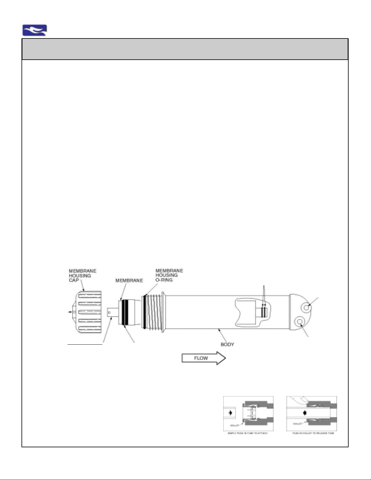
Replacement of Membranes - All RO Units
Step 1: Open dispenser/faucet. Lock handle in the up and open position and allow water to flow. Water will eventually
only drip then almost come to a stop. Now go to Step 2. Keep dispenser/faucet open until instructed to close.
Step 2: When water has come to a stop or very slow drip, Close inlet water supply to the system.
Step 3: Disconnect the water feed tube from the top of the membrane housing or the membrane housing cap (see the
end of the membrane housing with one fitting). See diagram below.
CAUTION: FOLLOW PROPER TUBING CONNECTION INFORMA TION (Found on Pages 4.1-13&14)
Step 4: Open membrane housing by turning membrane housing cap counterclockwise. Remove the old membrane.
NOTE - DIFFERENT STYLES FOR THE REMOV AL OF MEMBRANES:
Membranes come standard with a Nipple with T wo (2) O-Rings which inserts and seats into the back of the
membrane housing (see diagram below). Membranes come in two styles for the removal of the membrane from
the housing. Style #1 (pictured in diagram below), may require pliers to remove the membrane. S tyle #2 is
a threaded insert. Using a common screw, thread in clockwise and pull screw to remove membrane.
NOTE: See optional disinfection procedure of empty unit before replacing any filters, membranes, and/or UV lamp.
Step 5: Place a light coat of food-grade silicone grease or petroleum jelly (not included) on the Two (2) O-Rings and
Black Seal before replacement of the membrane.
Step 6: Insert the new membrane with the Two (2) O-Ring end in and allow to seat (see diagram below).
Step 7: Screw membrane housing cap back on.
Step 8: Re-insert feed water tube into the top of the membrane housing or the membrane housing cap (see diagram).
CAUTION: FOLLOW PROPER TUBING CONNECTION INFORMA TION (Found on Pages 4.2-13&14)
Step 9: ONCE NEW FILTERS/MEMBRANE HA VE BEEN REPLACED - CHECK AND FOLLOW ALL APPROPRIATE
STEPS FOR “SYSTEM ST ART-UP AND OPERA TION PROCEDURES”
CAUTION: WATER WILL BE PRESENT WHEN FIL TERS ARE CHANGED.
A pan, towel, etc. should be placed under the housings to catch any water .
LOCATION OF
WA TER FEED TUBE
AND CONNECTION
PRODUCT TUBE
PICTURED, STYLE #1
PULL TO REMOVE
(NOT PICTURED, STYLE #2
NO NIPPLE, SEE NOTE)
BLACK SEAL OR
BRINE SEAL
ENSURE PROPER
SEAL OR SEA T WITH
MEMBRANE HOUSING
NOTE:
It is recommended that membranes, if possible be tested annually for TDS and changed as needed, based on usage and
local water conditions. All filter housings with filters labelled
“Prefilter”, “Sediment” &/or “Carbon” must be replaced once a
year, or as needed, to protect membrane. The quantity and
quality of the water processed affects the life of all filters and
membranes.
CUT-A-WAY IN
HOUSING TO VIEW
MEMBRANE INSERT
NIPPLE WITH
(2) TWO 0-RINGS
PRODUCT WA TER
WHITE FITTING WITH
WHITE TUBING
REJECT WA TER
GRAY FITTING WITH
BLACK TUBING
illustrated quick connect fitting
and proper tubing connection
www.EWSWATER.com office: 702-256-8182 (m-f; 8:30-4:30, pst) fax: 702-256-3744 [email protected]
Page 20
4.2-20
EWS, Inc. / Environmental Water Systems
R.O. - Cleaning of Empty Housings
NOTE:
All containers, surfaces and items exposed to water can accumulate a clear or discolored film which may also be
slippery or slimey to the touch. This is a bio-film that is non-pathenogenic and usually of no harm.
This film is most commonly a nuisance and is readily wiped off. It is this reason we suggest a simple
cleaning procedure prior to returning new filters and membranes to the reverse osmosis system.
This procedure may be performed at any time when changing filters and membranes,
or after extended periods of inactivity of the system.
Step 1:
A: Empty All Available Filter Housings** by Following S teps 1 through 4: R.O. - Replacement of Filter Cartridges.
(Open faucet, Close inlet water supply , Empty all housings of their filters)
B: Empty Membrane Housing by Following S teps 3 and 4: R.O. - Replacement of Membranes.
(Step s 1 and 2 have been already done, see above “A”, Empty housing of the membrane)
**NOTE: All 4 and 5-S tage Units have In-Line PostFilters. These self-contained filters are not included in this procedure.
Step 2: Using disinfecting wipes, mild cleaning solution, and/or warm water and soap - simply wipe around the
housings and any exposed areas. Remove any film and/or discoloration. Repeat, if needed. Rinse thoroughly .
Step 3: Follow all procedures for the replacement of the filters and the membrane.
CHECK AND FOLLOW ALL APPROPRIA TE STEPS FOR “SYSTEM ST ART -UP AND OPERATION PROCEDURES”
RSR-100 and RSR-150 Control Valves
Installed on every R.O. Unit produced by EWS, Inc. This one control valve takes the place of up to 3 devices commonly
1) The control valve monitors the water entering the storage tank and when the storage
tank is full, the valve turns off the water processing of the system. Less Waste.
2) The control valve regulates the correct amount of reject water flushed to the membrane.
3) The control valve has a positive sealing check valve. The check valve accurately monitors
internal pressure and protects the system from pressure surges and reverse flows which
could damage the membrane.
Note: It is important to completely empty the storage tank monthly to provide a complete tank of fresh water to
prevent TDS “creep” which prevents the proper pressure on this control valve and within storage tank.
CT A Membranes
3-Stage Unit s only
needed in a reverse osmosis system and can be easily replaced if needed.
TFC Membranes
4- & 5-St age Units
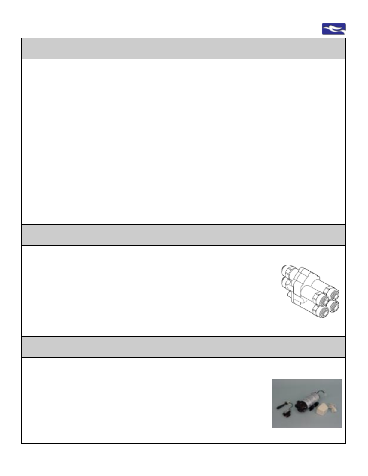
Correct Application of Booster Pumps (Five-Stage Units Only)
The pump is replaceable as needed and is always installed after the first stage (“Sediment”) and provides the proper
and required and constant pressure (minimum 40 PSI) through the membrane.
Booster pumps are critical to the effective performance of reverse osmosis membranes and
are recommended in applications where feedwater pressure is less than 40 PSI.Feedwater
high in Total Dissolved Solids (TDS) may need a boost, in order to perform within rejection
parameters.
Standard Components: Always connect in the following order:
1) Transformer 2) TSO-Tank Shut-Off Switch 3) Pump
T ank Shut-Of f Switch: Mounted in-line with the hydro-pnuematic pump as close to the tank
as possible, this switch will automatically turn the booster pump off when the tank is full.
www.EWSWATER.com office: 702-256-8182 (m-f; 8:30-4:30, pst) fax: 702-256-3744 [email protected]
Pump comes fully assembled
as option with RU500T35 units
Page 21

EWS, Inc. / Environmental Water Systems
NOTES
What unit(s) do I have? What filters do I need to order?
Reminder to Register your Purchase
ww.ewswater.com, click the “PRODUCT REGISTRATION” button,
then the link for “Online Interactive Registration”
4.2-21
Helpful Hint:
Find the enclosed Sp anner W rench that came with the unit and place it on top of the bracket.
When finished, roll up this Service Guide and place on top with wrench.
This Service Guide and the wrench will come in very handy when it’s time for filter replacement.
www.EWSWATER.com office: 702-256-8182 (m-f; 8:30-4:30, pst) fax: 702-256-3744 [email protected]
Page 22
4.2-22
EWS, Inc. / Environmental Water Systems
Water Fitration Systems Included in this Care and Use Manual
For Proper Installation, Information and Maintenance - Identify your Filtration System
check the unit
check replacements for easy future reference
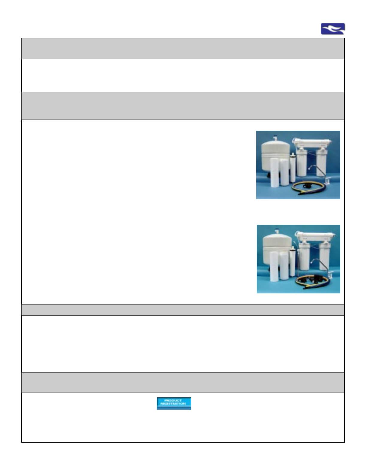
Reverse Osmosis Undercounter Filtration Units
Three Stage Common Municipal Series
Model No: RU300C18
Three stage undercounter reverse osmosis system contains a 5-micron pre-sediment filter which removes suspended matter, dirt, rust and sediment to improve
performance of other filters. The GAC postfilter removes chlorine and other volatile
organic compounds to improve taste, clarity and odor . The CT A membrane removes
inorganics, minerals, and total dissolved solids, lead and cysts (giardia and
cryptosporidium) and produces up to 18 gallons per day . Unit includes a 3.2 gallon
storage tank.
Meets or complies with NSF St andards 42 and 58.
Filter Replacement Codes: 1, 6, 1 1
Model No: RU300C18 w/UV
Three stage undercounter reverse osmosis system contains a 5-micron pre-sediment filter which removes suspended matter, dirt, rust and sediment to improve
performance of other filters. The GAC postfilter removes chlorine and other volatile
organic compounds to improve taste, clarity and odor . The CT A membrane removes
inorganics, minerals, and total dissolved solids, lead and cysts (giardia and
cryptosporidium) and produces up to 18 gallons per day . Unit includes a 3.2 gallon
storage tank. The additional UV module protects against bacterial, viral, E-coli and
other microorganisms and is tested 99% effective.
Meets or complies with NSF St andards 42, 58 and 55.
Filter Replacement Codes: 1, 6, 1 1, 16
All completely assembled reverse osmosis systems include the following standard features:
White 10" housing with filtration cartridges, spanner wrench to open housings for easy filter replacement, easy to use membrane
housing, chrome, lead-free faucet with white trim (with air gap adaptor) for dispensing water, self-piercing saddle valve for water
line connection with shut-off valve (see service guide for your correct application), all necessary tubing (color coded) to make
proper connections, simple to use mounting bracket, UV lamp and setup (UV unit only),pump (booster pump units only), drain
saddle and bladder tank, complete service guide with installation and use instructions.
All units are upgraded to produce more water and waste less. All units include a 3.2 gallon storage tank and we
incorporate our RSR control valve which monitors flow and operates as a check valve/backflow prevention and an automatic shutoff to protect the system.
Register this Product - It is a Requirement for Warranty
Visit www.ewswater.com, Click “PRODUCT REGISTRATION” Button
and Click the “Online Interactive Registration” link
EWS, Inc. will keep this information confidential and will offer you reminders to replace your filters and offer
you updates on water issues and concerns
www.EWSWATER.com office: 702-256-8182 (m-f; 8:30-4:30, pst) fax: 702-256-3744 [email protected]
Page 23
EWS, Inc. / Environmental Water Systems
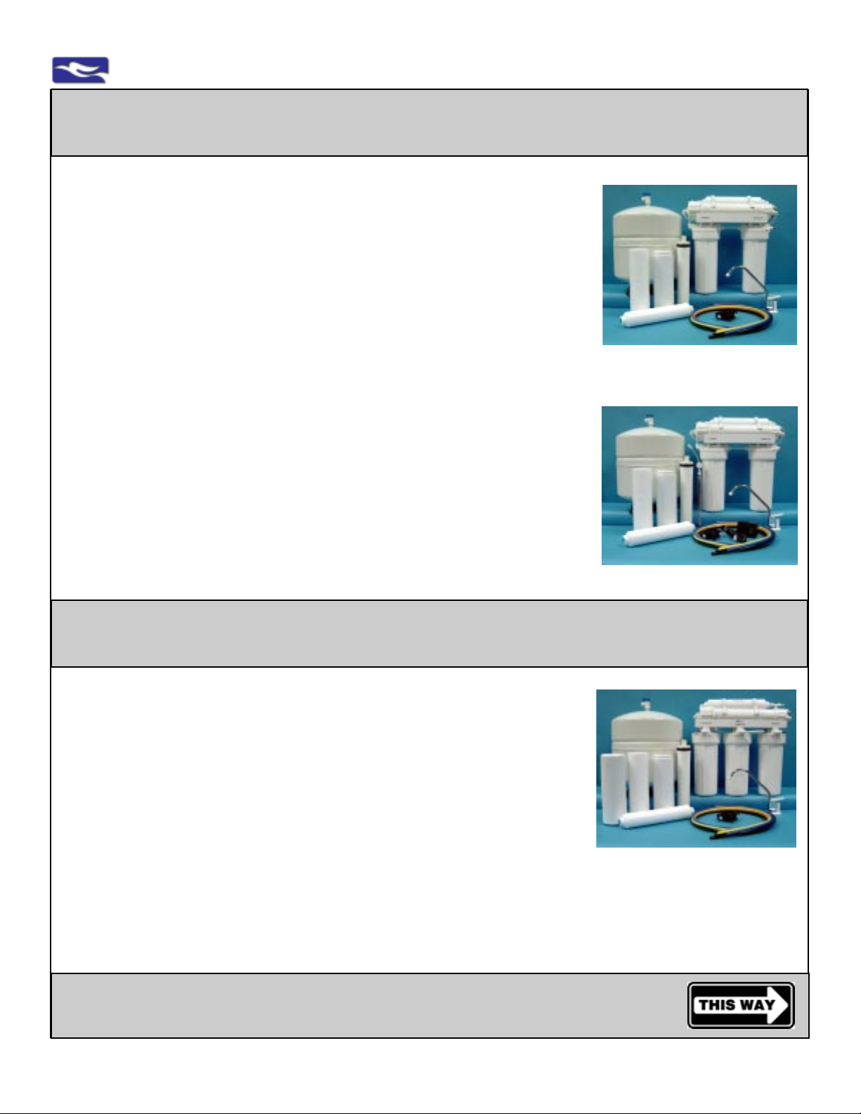
Reverse Osmosis Undercounter Filtration Units
Four Stage Well Water Series
Model No: RU400T35
Four stage undercounter reverse osmosis system contains a 5-micron pre-sediment
filter which removes suspended matter, dirt, rust and sediment to improve performance
of other filters. The GAC postfilter and GAC in-line filter remove chlorine and other
volatile organic compounds to improve taste, clarity and odor. The Thin Film Composite (TFC) membrane removes inorganics, minerals, and total dissolved solids, lead and
cysts (giardia and cryptosporidium) and produces up to 35 gallons per day. Unit includes a 3.2 gallon storage tank.
Meets or complies with NSF Standards 42 and 58.
Filter Replacement Codes: 1, 6, 12, 21
Model No: RU400T35 w/UV
Four stage undercounter reverse osmosis system contains a 5-micron pre-sediment
filter which removes suspended matter, dirt, rust and sediment to improve performance
of other filters. The GAC postfilter and GAC in-line filter remove chlorine and other
volatile organic compounds to improve taste, clarity and odor. The Thin Film Composite (TFC) membrane removes inorganics, minerals, and total dissolved solids, lead and
cysts (giardia and cryptosporidium) and produces up to 35 gallons per day. Unit includes a 3.2 gallon storage tank. The additional UV module protects against bacterial,
viral, E-coli and other microorganisms and is tested 99% effective.
Meets or complies with NSF St andards 42, 58 and 55.
Filter Replacement Codes: 1, 6, 12, 21, 16
4.2-23
Reverse Osmosis Undercounter Filtration Units
Five Stage for Heavy Sediment and/or Particulate Well Water Series
Model Nos:
Five stage series for unusually heavy sediment or particulate, potable (non-chlorinated)
well water. Three stages to protect and filter prior to TFC membrane with post filter for
polish. A vailable with or without either UV module or booster pump.
Meets or complies with NSF Standards 42, 58 and 55 with UV option.
Filter Replacement Codes: 1, 6, 12, 21, 22, Optional 16
***A booster pump is used with a reverse osmosis system to provide the proper rejection rates. The unique design features
of the pump provide superior performance characteristics to deliver a near constant “boost” pressure to the R.O. membrane
required in low inlet water pressure applications or extreme conditions that effect pressure over the membrane and R.O.
performance.
RU500T35
RU500T35w/UV
RU500T35w/BP***
RU500T35w/BPw/UV
Filter Replacements and How to Order
www.EWSWATER.com office: 702-256-8182 (m-f; 8:30-4:30, pst) fax: 702-256-3744 [email protected]
Page 24
4.2-24
EWS, Inc. / Environmental Water Systems
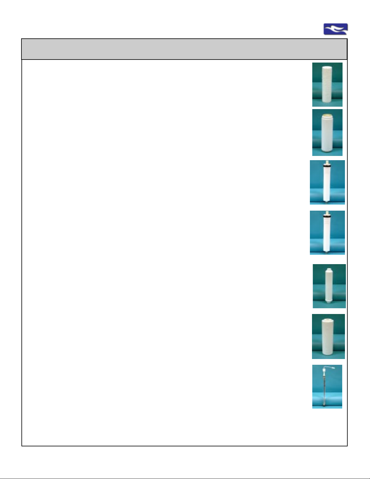
Filter, Membrane and UV Lamp Replacements
Easy Reference: Filter Code No: 1 Replace: UP TO A YEAR*
Model No: 93023 Pre-Sediment Filter (5-micron)
5-Micron Prefilter (93023) is a pure polypropylene full-bed depth filter with exceptional dirt holding capability .
The removal of any dirt, silt, rust or suspended matter protects the remaining cartridges and extends the
performance of other filters and membranes. Meets FDA requirements for food and beverage contact.
In Use: All Reverse Osmosis Units (all housings on the right side of unit at the “Feed” water)
Easy Reference: Filter Code No: 6 Replace: UP TO A YEAR*
Model No: UDF10HP Granular Activated Carbon (GAC) Postfilter
UDF10HP is designed for effective reduction of taste, clarity and odor problems such as Chlorine and
VOC's. Cartridges are designed to allow water to pass through entire carbon bed to allow maximum
adsorption. Meets or complies with NSF S tandard 42.
In Use: All Reverse Osmosis Unit s (“Postfilter” on 3- & 5-St age Units, “Carbon” on 4-S tage Units)
Easy Reference: Filter Code No: 11 Replace: UP TO 18 Months*
Model No: CT A-RO CTA Membranes - Reverse Osmosis Systems
CT A membrane (CT A-18) removes Total Dissolved Solids to improve the taste and quality of water. T ap water
is forced by pressure through a semi-permiable membrane while dissolved solids and particulates are left
behind. The CT A membrane is chlorine tolerant and is used (on all 3-S t age Units) correctly on municip ally
treated water or treated well water. Meet s or complies with NSF St andard 58.
In Use With: RU300CI8, RU300C18w/UV
Easy Reference: Filter Code No: 12 Replace: UP TO 18 Months*
Model No: TFC-RO TFC Membranes - Reverse Osmosis Systems
TFC membrane (TFC-35) removes T ot al Dissolved Solids to improve the taste and quality of water. T ap water
is forced by pressure through a semi-permiable membrane while dissolved solids and particulates are left
behind. The TFC membrane, even though it provides more water per day, is chlorine intolerant and used
correctly only on potable, non-chlorinated water . Meets or complies with NSF S tandard 58.
In Use With: RU400T35, RU400T35w/UV , RU500T35 series
Easy Reference: Filter Code No: 21 Replace: UP TO A YEAR*
Model No: IL210C 2” x 10” In-Line Carbon Filter
Designed specifically to eliminate objectionable tastes and odors from the water supply. This postfilter will
reduce most other contaminates that may find their way past the RO membrane to polish the taste of the
water. Used in all four and five st age reverse osmosis systems. Meets or complies with NSF S tandard 42.
In Use With: RU400T35, RU400T35w/UV , RU500T35 series
Easy Reference: Filter Code No: 22 Replace: UP TO A YEAR*
Model No: OCB Granular Activated Carbon (GAC) Filter (OCB)
Designed as a high density GAC filter used as a “Prefilter” to protect the membrane in all 5-Stage Series
Units for difficult well water applications. Meets or complies with NSF S tandard 42.
In Use With: “PREFIL TER” on All 5-Stage Series
Easy Reference: Filter Code No: 16 Replace: ANNUALLY*
Model No: UST -200 RL (lamp only) UV Lamp - UV Bacteria-Kill Units
UV Unit (UST-200) cont ains a 6 Watt UV lamp that effectively kills bacteria (>99%). A 316 Bonded S tainless
Steel Interior enhances kill power by reflecting UV light and eliminates degradation of polypropylene housing.
Due to advanced design, water is spun through the module to eliminate shadowing and shading which
additionally maximizes kill power. UV Module meet s or complies with NSF S tandard 55.
In Use: All Reverse Osmosis Units with UV Option (w/UV)
*Replacement of all filters and membranes are based on local water conditions and usage.
UV lamp replacement annually (or, as needed within the year)
For all removal capacities, test results and compliances. Visit www .ewswater .com
www.EWSWATER.com office: 702-256-8182 (m-f; 8:30-4:30, pst) fax: 702-256-3744 [email protected]
Page 25
EWS, Inc. / Environmental Water Systems
4.2-25
Ordering Filters, UV Lamp Replacements, and Parts
There are several ways to obtain and order filter replacements for your unit.
Contact;
... your builder, plumbing contractor and/or your inst aller that provided the product...,
... the kitchen & bath showroom, distributor, and/or ret ailer where you purchased the product...,
... or use the internet in the following manner...,
Go to our Corporate Site @
top right side of every page. Click on your S tate and scroll towards a distributor. You can call someone
close to you (hopefully someone will be responsive), let them know what you have, and they can place
your order. As a manufacturer , EWS, Inc. does not sell direct to consumers, only into distribution.
The most convenient way to purchase the correct filters for your unit may be to visit an
authorized web distributor such as www .waterontheweb.com
Follow these easy instructions to obtain the correct filters for your system;
1......... Click on “Products” button,
2......... On right side of that page, find “Filter Replacements” and click here,
3......... Find “Filters by Sink Product” and click,
4......... Identify the unit you own and click on the model #, (for example RU300C18)
5......... Click on the “Place Order” button to order your complete set of filters for your
particular unit. Now just follow the secure store instructions to complete the
purchase and you’re done.
Waterontheweb is very similar to the EWS Corporate Site in order to provide the consumer with the
most complete information and an e-commerce solution to the consumer’s needs. This site is designed to be simple and prevents any confusion as to what items are needed for any particular unit.
This distributor will place their order with EWS, Inc. (similar to any other distributor) and will ship your
order directly to the address you designated in the store.
www .ewswater.com and note the “Showroom Locator” button towards the
To order needed parts from the same authorized internet distributor;
1......... Click on “Products” button,
2......... On right side of that page, find “Parts” and click here,
3......... Find your part(s) by scrolling the clearly described items,
4......... Click on the “Order” button to order a part (return to this page if you need more
items) for your particular unit. Once complete, just follow the secure store instructions
to complete the purchase and you’re done. Call or e-mail us if you need any help.
Thank you and we hope we have been of assistance in this matter .
EWS, Inc. and Environmental Water Systems – Customer Service
www.EWSWATER.com office: 702-256-8182 (m-f; 8:30-4:30, pst) fax: 702-256-3744 [email protected]
Page 26
4.2-26
EWS, Inc. / Environmental Water Systems
Maintenance Guide - Reverse Osmosis Systems
INITIAL INST ALLA TION
Follow the proper procedures for the set-up, installation and start-up of all systems. Problems (short and long-term) occur
when the systems are installed incorrectly . If any questions arise after installation, consult the trouble shooting guide for
assistance.
NOTE; ONCE INST ALLED CORRECTLY, THE MORE CONSISTENTL Y THIS PRODUCT IS USED THE BETTER.
REPLACEMENT OF FIL TERS, MEMBRANES, AND UV LAMPS (if applicable)
Follow the proper procedures for the shut-down of system, and the removal and replacement of the filters, membranes and/
or uv lamp (if applicable). Once a replacement procedure has been completed, the proper start-up of all systems is again
as important as it was when the system was first installed. If any questions arise after replacement procdures, consult the
trouble shooting guide for assistance.
Note: If the system was fine and only started having issues after the replacement of filters, membrane, and/or uv lamp,
than some procedure was not properly followed when re-starting the system.
MAINTENANCE
Reverse osmosis systems can be a sensitive product not applicable to other drinking water filtration systems because of
these various issues;
• Interconnection of system to a storage tank to store production water
• Interconnection of system to a drain line for draining rejection water
• Need for proper line pressure over the membrane for proper water quality and overall function
• Limits to the quantity of available water due to production rates over a day (divide by 24 provides
the RO production capacity over an hour) If you empty a tank it can take hours to refill before usage
• Interconnection to other devices, length of tubing for filtered water to travel and the potential for
warranty issues with other items due to the aggressive nature of RO water
MONTHL Y
Empty S torage Tank
This is a little trick you won’t get from someone trying to sell you a service/maintenance agreement.
Empty water from and close any other devices connected to RO unit. Open and lock your dispenser in place in order to
empty storage tank completely of water . If you have a dispenser that does not lock open than hold open until tank has
been emptied. Wait until you see the water come to a very slow trickle or drip. Close dispenser and allow RO to manufacture a completely new and fresh tank of water. Do this overnight to allow RO to produce enough water before you rise the
following day . Once tank is refilled than open other devices connected to RO. This procedure keeps the proper pressure on
the tank bladder and on the RSR control valve and allows better water flow , quality and quantity .
Check System
Visually check dispenser connections, system connections and drain. Be aware of any excessive household water
pressure or changes in your incoming water quality as well as changes in the production water.
YEARLY
Replacement of filters, filter cartridges, in-line filter cartridges, and uv lamp (if applicable).
Note: Replace, as needed, due to local water conditions and usage but do not exceed one year.
Membrane can be replaced as a convenience with all other filters on an annual basis (Purchased as a set for your
specific RO system). However, membrane may last between 18 months up to 3 years, based on local water conditions
and usage.
STORAGE OF UNIT OR PROLONGED PERIODS OF INACTIVITY, if applicable
Empty tank completely , shut off water supply to unit, remove filters and membrane and store in a cool dry location or
refrigerator.
Upon return, begin a disinfection procedure prior to any filter/membrane replacement, replace filters and membrane,
and begin start-up procedure as if it were a new unit.
Regarding a disparity of issues with other competitive RO product. EWS, Inc. does not skimp on quality to produce a
cheap product. EWS, Inc. provides the best in product with the most complete information.
www.EWSWATER.com office: 702-256-8182 (m-f; 8:30-4:30, pst) fax: 702-256-3744 [email protected]
Page 27
T rouble Shooting Guide - Reverse Osmosis Systems
Problems
with Start-Up &/or
Filter Replacements
No water after installing the
system
EWS, Inc. / Environmental Water Systems
Possible Causes Solution
Improper start-up of the unit upon
installation or filter replacement
Start with the start-up procedures and follow them as
if the unit was just installed
4.2-27
No water after replacing
filters, in-line filters, &/or
membranes
It takes hours after a proper install
to have a full tank for use
The interconnection between the inlet, outlet, drain and tank lines can
cause air in the unit at the RSR control valve. Air in lines, and at this
valve, will not allow R.O. to function
properly.
Tank valve is closed
Tank pressure is off,
Tank pressure too low or too high
Make sure start-up was performed correctly and wait
for tank to fill. Follow instructions for proper start-up
Air in Lines “Burping Procedure”
Close the tank valve,
Close (if applicable) water supply to other devices that
may be connected to this unit,
Open and lock dispenser (observe sputtering from dispenser or a slow drip).
Rotate the entire unit 90° degrees clockwise and hold in
vertical position, after a minute return unit back to horizontal position ,
Then rotate the entire unit 90° degrees counterclockwise and hold in that vertical position, after one minute
return unit back to horizontal position,
Water should drip at a steady flow (about 1-11/2 gallons
per hour) without sputtering or any gurgling sound.
REPEAT AS NEEDED.
Then close the dispenser, open tank valve, only open (if
applicable) water supply to other connected devices once
andonly once the tank has filled completely.
Open valve, in line or parallel with yellow tubing, close
other devices and begin proper start-up procedure.
The tank air pressure should be 5-7 psi without water in
tank for proper operation. Pressure variances due to
higher elevations may occur. Under or over-inflation will
prevent proper operation of system. Check with accurate (0-20) gauge Empty tank and adjust (if needed) using a bicycle or sports ball pump. Begin proper start-up
procedure
Connections of tubing incorrect
Drain line and/or drain hole restricted
or clogged
Saddle tapping valve piercing not
complete, if applicable
Leak at fittings and tubing
Leak at dispenser or air gap
Leak at housings
Electrical (if applicable)
Water flow and quantity
issues
Water quality issues
Drain issues
www.EWSWATER.com office: 702-256-8182 (m-f; 8:30-4:30, pst) fax: 702-256-3744 [email protected]
Various Possible Causes
******************************
Please review this comprehensive
troubleshooting guide
to determine the cause
Inspect and follow all connections of all tubing
Follow proper instructions for Air Gap installation and
connections
Check hole for proper draining and proper drain saddle
installation
Check for proper drain location
Follow instructions to re-do piercing or use the
preferred method to make this connection
Various Solutions to Specific Issues
*****************************************
Please consult this comprehensive
troubleshooting guide
to determine the solution to various RO issues
Page 28
4.2-28
EWS, Inc. / Environmental Water Systems
T rouble Shooting Guide - Reverse Osmosis Systems
Problem - Leaks
Connections & Tubing
Any or All Leaks
Leaks at any of the
FOUR (4) INSTALLED
Tubing Connections:
See colors below:
Red - Incoming Supply
Blue - to Dispenser
Yellow - to Tank
Black - to Drain
Leak at FACTORY INSTALLED
fittings (only white tubing)
Possible Causes Solution
Excessive pressure or pressure
surges above 65 PSI
Various causes to inspect
See the Following;
•If cut, is the tubing cut with a
straight end to grab squarely?
•Is the tubing inserted completely
into fitting?
•Broken collect or fitting
•Is there a problem with the collet
and the quick-connect fitting?
•Tubing incorrectly removed
•Damaged in shipping,handling,
and/or delivery
Same as above
Pressure reducing valve (PRV) at main water supply
to maintain pressure at or below 65 PSI or the addition of a Pressure Limiting Valve (item# FMP-60) on
the inlet tube prior to the point of use unit
•Follow instructions for Connection of Tubing.
Access the filter unit, remove tubing by depressing
the collet and pulling tubing out. Using a utility razor
knife,
squarely cut 1/2" off tubing from the end. Make
sure end of tubing is not flattened Reinsert the tubing
into the fitting as far as possible. Check for leaks.
•Tug on tubing (do not pull hard) to check fitting and
the integrity of the connection
•Upon inspection, prior to install or a result of proper
start-up and inspection and fitting is damaged,
Replace simple part (call for proper fitting part)
Same as above
Leak at plastic compression
fitting at UV Module
(option, if applicanle)
Leak at Inlet Water Supply
Connection
Damaged in shipping,handling,
and/or delivery
Various causes to inspect.
Saddle tapping valve may not be
applicable or installed correctly
Replace simple part (item# fc-uv-jaco)
•Check connections and/or correct.
•Follow the inlet supply water instructions in this
manual and/or install the preferred inlet connection
Leaks - Faucet Possible Causes Solution
Leak at the supplied
dispenser/faucet spout
Leak at the supplied
dispenser/faucet base by
handle (brass “T”)
Leak at the connection to
supplied dispenser/faucet
Leak at another Mfg’s faucet
and/or connection to another
device
Water running out of Air Gap
adaptor of faucet
Spout needs to be re-inserted
O-ring issue at inserted brass
piece or “T” that holds and operates handle
Compression fitting and other
connections need to be properly
made
All connections need to be
properly made
Black 1/4” & 3/8” tubing
misinstalled or backwards
Drain saddle not allowing water to
drain into trap properly
•Spout pulls out from faucet body that’s why it swivels.
Spout has 2 o-rings at base and is inserted
completely into bottom of body to prevent leaking.
•Replace the supplied faucet dispenser
(item# depends on any finish option)
•Check connections at various locations and
re-connect, re-insert, tighten and/or correct.
•Consult with Mfg of other product and/or installer to
check connections at various locations and reconnect, re-insert, tighten and/or correct.
Follow proper instructions for Air Gap installation and
connections
Check hole for proper draining and proper drain saddle
installation
Check for proper drain location
www.EWSWATER.com office: 702-256-8182 (m-f; 8:30-4:30, pst) fax: 702-256-3744 [email protected]
Page 29
EWS, Inc. / Environmental Water Systems
T rouble Shooting Guide - Reverse Osmosis Systems
Leaks - Housings Possible Causes Solution
4.2-29
Leak at cartridge housing,
Leak at membrane housing,
or UV housing (if applicable)
Misaligned, damaged or
missing o-ring
At Cap: Misaligned, damaged or
missing o-ring
Cracked housing due to excessive
water pressure issues, misaligned
filter cartridge in housing and/or
overtightening
•Locate and align O-ring into groove inside cartridge
housing,
•Same for o-ring in membrane or uv housing caps
•Replace simple o-ring part for correct housing
•Replace housing part (item # h-filter, h-membrane, or
h-uv) and correct issue that caused the problem (no
plumbing needed)
Water Flow Issues Possible Causes Solution
No water
Not enough water
Water supply is off
Saddle tapping valve piercing not
complete or clogged, if applicable
Low water pressure
Incorrect Tubing Connections
Storage tank depleted
Other devices connected to
system demanding too much
water, too many other devices
•Turn main water supply on
•Saddle tapping valve not open, if applicable
•Turn water on at inlet connection, other if applicable
•Follow instructions to re-do piercing or use the
preferred method to make this connection
•Unit may not operate properly at less than 35 PSI
feed line pressure (max: 65 PSI)
•Follow instructions to connect tubes to proper fittings
•Empty tank needs to fill over several hours
•Close other connected devices and allow tank to
completely fill.
•Maximum limit to storage tank and 2 other devices
Water flow is restricted
Low flow from unit
Lengthy plumbing run, vertical
plumbing, unit in a remote location
Storage tank pressure is wrong
Storage tank valve not opened
“TDS” Creep
See RO Maintenance
Kinked or bent tubing
Saddle tapping valve, if applicable
may be restricting flow or misapplied on type of pipe being used
(only applicable on hard pipe of
copper, brass or steel)
Clogged prefilter cartridge and/or
other cartridges
•Total length of combined tubing to tank, faucet, and
other devices not to exceed 20 feet. Vertical piping
not applicable. Remote unit location is discouraged.
•Tank needs 5-7psi without water. Too much or too
little and tank will not fill and dispense water properly.
Check tank pressure with (0-20) gauge. Empty tank
than use bicycle or sport ball pump to adjust
•Empty tank completely and allow system to produce
a new tank of water, empty and repeat
Make longer loop with tubing to remove kink or bend
Back the end of the piercing lance out, turning the
handle counter-clockwise. Then re-insert by turning
the handle of the saddle tapping valve clockwise until
it is again firmly seated. This will clear any possible
debris that can block piercing lance and water flow.
If there is flow rate through unit without filters then
there is a need to replace sediment and/or other
filters based on water conditions and usage
www.EWSWATER.com office: 702-256-8182 (m-f; 8:30-4:30, pst) fax: 702-256-3744 [email protected]
Page 30
4.2-30
EWS, Inc. / Environmental Water Systems
T rouble Shooting Guide - Reverse Osmosis Systems
Problem - Water Quality Possible Causes Solution
Water Cloudy
Salty Taste or Whitish
Ice Cubes
TDS Test less than
75% Rejection
Air in system
System start-up
Filter or membrane replacement
New installation, changing filters,
disinfecting the system
Open/close and open of water supply to
home or in home
Membrane seals
Hot or High feed water temperature
High feedwater TDS
RO Membrane replace
High feedwater temperature
Post filter elements
Air in the system is a normal occurrence with initial
start-up of the RO system. This milky or cloudy
look will disappear during normal use within 1-2
weeks. Condition can reoccur after any filter
change-out
Empty and fill tank 3 times to reduce air and fines
from system and/or filter replacement start-up
Membrane seals are breached, re-seat or replace
membrane
Water supplied to unit must be below 95°F
Feedwater TDS levels above 500 ppm can result in
lower quantity and quality product water. 1 psi loss
per every 100 ppm above 500 ppm.
Treat the same as low feedwater pressure. Increase water line pressure or may need booster
pump for system
Membrane replacement should occur when rejection rate has dropped below 70%
Feedwater temperatures above 95°F can produce
problems, cool water or find another supply
New post filter elements can release small air
bubbles and small fines which show as additional
TDS in the product water. Follow proper start-up
instructions
Low Quality Water
Taste, Odor
(also see next page)
Unpleasant taste and/
or odor
Metallic flavor
Discoloration
Rotten egg smell from
water
www.EWSWATER.com office: 702-256-8182 (m-f; 8:30-4:30, pst) fax: 702-256-3744 [email protected]
Pre- and Postfilters
Pre-Treatment needed
Filter/Membrane/UV housing issues
Storage tank water issue
Need to replace filters
System needs disinfecting
System was idle, stored or misused
for a long period of time.
System under unfavorable conditions or
changing water conditions
Hydrogen sulfide, iron, manganese is in
the household water supply, presence of
iron/sulfur bacteria
System misapplied
Pre- and Post filters require replacement
Feedwater pretreatment may be necessary for
water supplies with high levels of iron, hydrogen
sulfide, water hardness, etc. which may be exceeding system tolerance parameters
Disinfect and inspect housings
Empty tank, sanitize, empty, flush and refill
Replace filters and follow start up procedures
Follow disinfection procedure
Flush system by running water, replace filters and/
or disinfect
Determine what changed in your water supply and
Flush, Replace and/or Disinfect, or change type of
water treatment system based on local water
conditions. Call your municipality or have your well
tested.
Hydrogen sulfide, iron and manganese must be
removed from household water supply before filter
system.
Visit our web site for other systems.
Page 31
EWS, Inc. / Environmental Water Systems
T rouble Shooting Guide - Reverse Osmosis Systems
Problem - Water Quality Possible Causes Solution
High Total Dissolved
Solids (TDS) in the
Product Water
Low Quality Water
Taste, Odor
and/or
Tank fills too fast
TDS “Creep” Tank has never been At night before bedtime, open dispenser, close other
completely emptied devices, then empty all the water from the tank. Allow
water toproduce overnight. Open other devices after
tank is completely filled. Do this quarterly or as
needed.
Clogged prefilter(s) Replace filter(s)
Low water pressure Feed water pressure must be above 40 psi
Check incoming supply water at inlet
RO membrane is new New membrane has a preservative. Follow correct
start-up procedure and empty tank 2 times before
usage
RO membrane issues Remove and check membrane. Inspect 2 O-rings
Membrane o-rings, brine seal at insertion end,
check brine seal for proper seating into membrane
housing
RO membrane is expended If membrane life is unusually short, find and correct
the problem. Replace membrane.
Product water and drain water Correct tubing and plumbing connections
tubing or connections are crossed
4.2-31
Low Quality Water
Taste, Odor
and/or
Tank fills too fast
No drain flow Clear or replace drain restrictor. Drain line is
clogged or restricted
Clear or replace air gap line or faucet
The RSR valve is not closing “TDS Creep” (see above) empty tank completely
and produce a new tank of water. Do this at least
4 or more times a year. Make sure pressure in
tank is between 5- 7 lbs.
Repair or replace RSR valve components
New in-line activated carbon post Flush with several full tanks of product water
filter or activated carbon cartridge
not rinsed completely
The feed water TDS has increased An increase in feed water TDS will give a
corresponding increase in product water TDS
Chlorine in feed water to membrane CTA membrane on 3 Stage unit is tolerant to
chlorine levels up to 2 ppm
TFC membrane on 4 & 5 Stage units are not
chlorine tolerant
Change or add precarbon filter to remove chlorine
Restricted brine flow Blocked brine line will foul membrane, decreasing
production and rejection rate. Check the drain line
for obstructions or restrictions blocking the flow
into the drain pipe and air gap (if applicable).
Low feedwater pressure over membrane Feedwater below 60 psi will produce lower quantity
and quality than the membrane specifications.
High TDS - total dissolved solids Feedwater less than 35 psi should consider using
reducing feedwater pressure over a low pressure boost pump. Booster pump requiremembrane ment, inquire with web site or our offices
High feedwater pressure Feedwater above 65 psi should be regulated to
a maximum of 65 psi into the system
www.EWSWATER.com office: 702-256-8182 (m-f; 8:30-4:30, pst) fax: 702-256-3744 [email protected]
Page 32
4.2-32
EWS, Inc. / Environmental Water Systems
T rouble Shooting Guide - Reverse Osmosis Systems
Drain - Issues Possible Causes Solution
No drain water
Leaking drain assembly
Leak from air gap opening in
faucet or Water running out of
Air Gap adaptor of faucet
Excessive drain noise or
gurgling coming from faucet
More than usual or excessive
drain noise or gurgling due to
rapid water flow on older
systems
Clogged brine restricter
Misalignment of hole in drain
saddle.
Black 1/4” & 3/8” tubing
misinstalled or backwards
Drain saddle not allowing water
to drain into trap properly
Drain assembly installed on bad
or non-preferred part of your sink
drain
Hole or drain tube is blocked or
obstructed with debris
Excessive slack in drain tubing
High feedwater pressure
Air trappped in system echos the
sound of water flow
Membrane breached seals, worn
Same issues with Low Water
Quality Troubleshooting
Replace brine restricter
Realign drain saddle, check for open drain hole
Follow proper instructions for Air Gap installation and
connections
Check hole for proper draining and proper drain
saddle installation
Check for proper drain location
Check hole for proper draining and proper drain
saddle installation
Check for proper drain location
Remove debris or restriction
Cut off excess drain tubing
Incoming pressure should not exceed 65 psi
Follow the warning in the middle of page 4.2-16 and
follow the “Burping” Procedure to remove air in the
lines
Re-align membrane or replace worn membrane
Follow troubleshooting for low water quality and fast
filling tank, this creates greater drain water flow.
High or greater water usage
Tank needs to fill more often due to greater usage
Electrical (if applicable) Possible Causes Solution
UV not working
Booster pump not working
Lamp damaged, lamp cord has not
been connected,
Transformer is not plugged in or
connected to wrong type of outlet
Lamp has burned out
Transformer not working
Pump cord not been connected
Transformer is not plugged in or
connected to wrong type of outlet
Transformer not working
Pump not working
•Connect lamp cord and/or Plug in transformer.
•Make sure unit plugged into an unswtiched electrical
outlet. Check GFI reset. Surge suppression is highly
recommended
•Replace UV Lamp
•Replace UV Transformer
•Connect pump cord and/or Plug in transformer.
•Make sure unit plugged into an unswtiched electrical
outlet. Check GFI reset. Surge suppression is highly
recommended
•Replace Transformer
•Replace Pump
www.EWSWATER.com office: 702-256-8182 (m-f; 8:30-4:30, pst) fax: 702-256-3744 [email protected]
Page 33
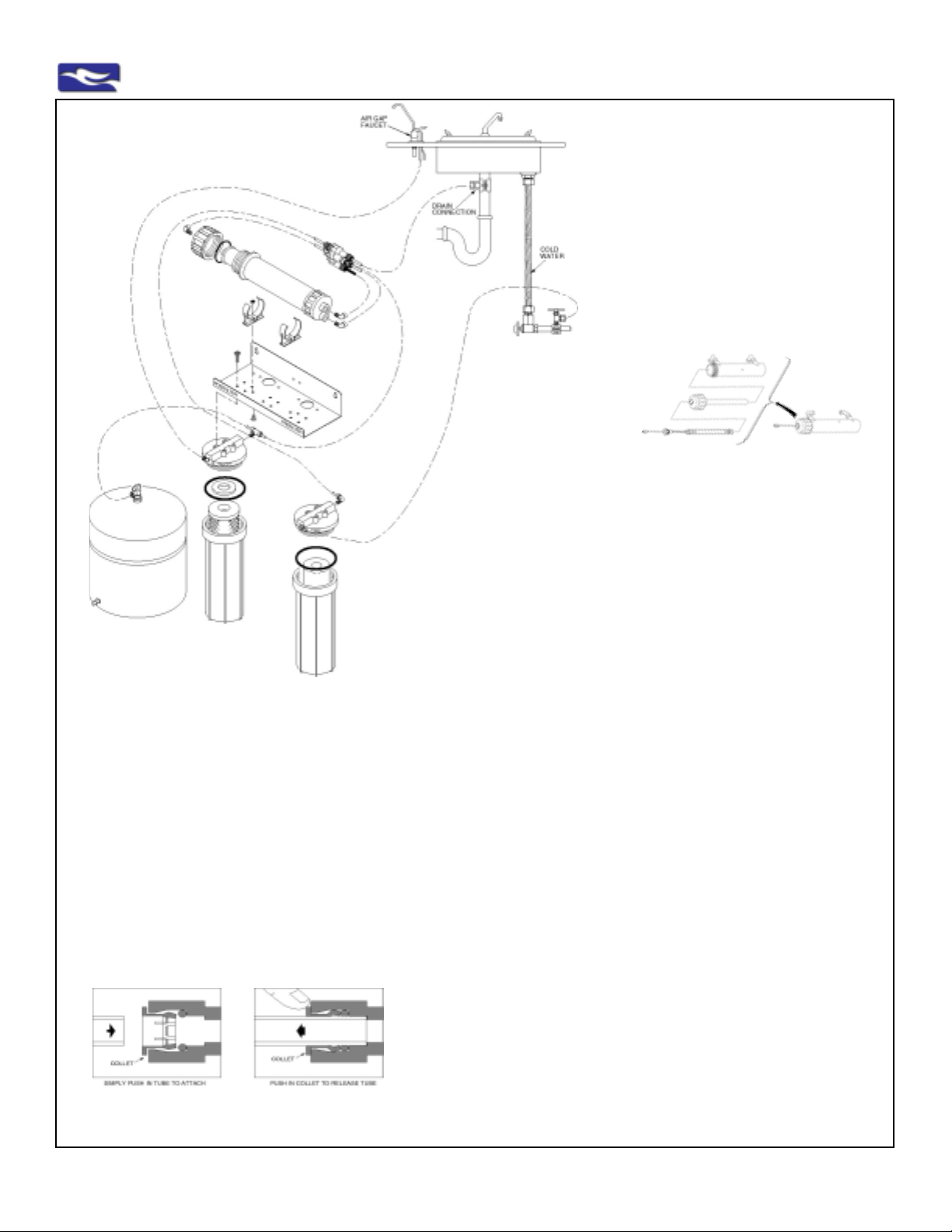
EWS, Inc. / Environmental Water Systems
4.2-33
See faucet
information
on Pgs. 4-7
18
5, 6
12
8
10
9
4
3
23
21
15
2
29
14
1
8
13
13
9
7
28
24
28
3
Path of Water Flow through System
from inlet water supply
1 through Prefilter (93023) then
2 through Membrane (CTA-RO) then
2a through UV Module (if applicable)
into S torage Tank until needed
When water is needed
water flows from Storage Tank
3 through Postfilter (UDF10HP) then
through dispenser or into another
device (if applicable)
illustrated quick connect fitting
and proper tubing connection
20
16
22
11
19
Basic Supplied
Connection
See Preferred Inlet
Supply Water
Connection Pg. 9
Ref. No.
Option
1
2
3
4
5
6
7
8
9
10
11
12
13
14
15
16
18
19
20
21
22
23
24
25
28
29
17
26
27
---
91
92
93
94
95
--31
Part No.
h-membrane
ro-tank 03.2
h-filter
93023
fc-rsr-wh
fc-rsr-gy
fc-ro-svl-t
CI480821W
CI480822W
ro-brkt-3
ro-clamp kit
PI480821S
h-m-clip
CTA-RO
ro-tank valve
fd-ch-wh
ro-rsr-cta
STV-2
t-blk-drain
t-blue
t-orange
t-yellow
UDF10HP
PI010822S
h-f-o-ring
020-MVH-0
Not Shown
fd-ag-wh
PI011222S
t-blk-gap
WRENCH
See Above
H-UV
n/a
n/a
UST-200 RL
fc-uv-jaco
Not Shown
POU-UV-E68
PPC212W
Three-Stage
Reverse Osmosis
Schematic, Parts, Installation:
Non-Air Gap Pictured
for illustration purposes only
For Air Gap Schematic
See Pg. 6
Optional: UV Disinfection Module
shown below
92
93
94
31 Double Clips not shown
Description
M/H; STRAIGHT PORT
RO102W 3.2 GALLON T ANK 141S152
#10 SL WHITE/WHITE WO/PR 158125
PX05-9 7/8" 5M SED CARTRIDGE
JG 1/4" X 1/8" M COMM - White on RSR
JG 1/4" X 1/8" M COMM - Grey on RSR
JG 1/4" SWIVEL BRANCH T
JG 1/4" X 1/8" FIXED ELBOW; WHITE
JG 1/4" X 1/4" FIXED ELBOW; WHITE
.090 ALUM BRACKET; PWDER COA T,HS-03A-W
DRAIN CONNECTOR; 1/4" FPT PDC602F
JG 1/4" X 1/8" FIXED ELB; GRAY
WHITE 2" FAST CLIP PPC202W
CTA MEMBRANE
1/4" FQC X 1/4" FPT EL-V AL VE PPSV -500822W
LONG REACH FAUCET ; WH/WH QMP-102W
90 GPD RSR FLOW CONTROL, RSR100-90
SELF PIERCING SADDLE VAL VE
1/4" PE TUBING; 60"; BK-P , DRAIN
1/4" PE TUBING; 60"; BL-P , OUTPUT
1/4" PE TUBING; 60"; OR-P , INPUT
1/4" PE TUBING; 60"; YL-P , T ANK
10" GAC CARTRIDGE
1/4" X 1/4" MALE CONNECTOR
HOUSING O-RING , FH4000
O-RING KIT
See Dispenser/Faucet w/Air Gap, Pg. 6
AIR GAP FAUCET ADAPTER
3/8" X 1/4" MALE CONECTOR-Air Gap Kit
3/8" PE TUBING BLACK - Air Gap Kit
SPANNER WRENCH FOR FIL TER HOUSINGS
UV Disinfection Module Shown Separately
FULLY ASSEMBLED MODULE ON T OP OF UNIT
UV MODULE HOUSING
UV CAP , O-RING AND GLASS SLEEVE
UV LAMP AND LAMP CORD
JACO 1/4"COMPRESSION X 3/8" FIXED ELBOW
UV ELECTRIC 24 V TRANSFORMER
DOUBLE CLIP - WHITE
95 95
91
www.EWSWATER.com office: 702-256-8182 (m-f; 8:30-4:30, pst) fax: 702-256-3744 [email protected]
Page 34
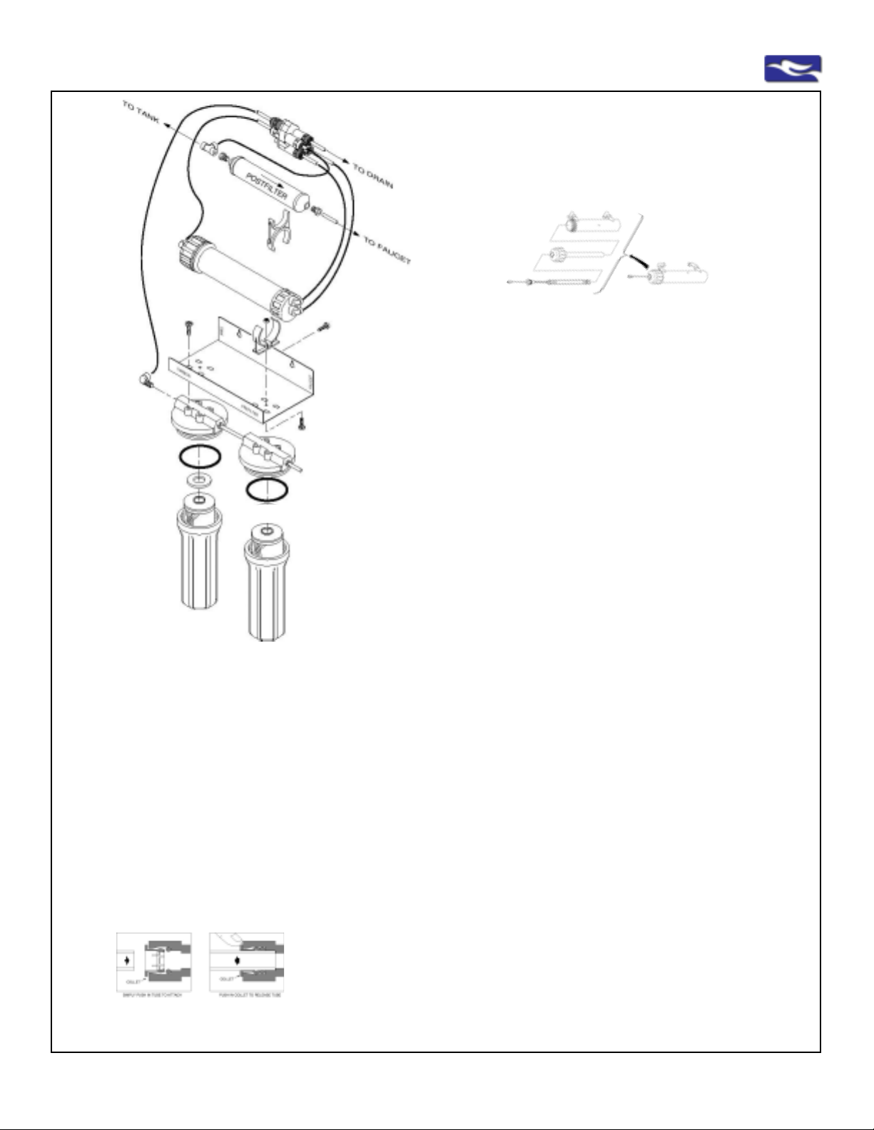
4.2-34
EWS, Inc. / Environmental Water Systems
23
18
5, 6
7
30
8
29
inside
inside
9
31
1
14
13
10
28
25
12
8
9
20
22
24
28
4
3
3
Path of Water Flow through System
from inlet water supply
1 through Prefilter (93023) then
2 through Carbon cartridge (UDF10HP) then
3 through Membrane (TFC-RO) then
3a through UV Module (if applicable)
into S torage Tank until needed
When water is needed
water flows from Storage Tank
4 through Postfilter (in-line, IL210C) then
through dispenser or into another
device (if applicable)
illustrated quick connect fitting
and proper tubing connection
21
Ref. No.
Option
Four-Stage
Reverse Osmosis
Schematic, Parts: for illustration purposes only
Optional: UV Disinfection Moduleshown below
92
1
3
4
5
6
7
8
9
10
12
13
14
18
20
21
22
23
24
25
28
29
30
2
15
11
19
16
17
26
27
---
91
92
93
94
95
--31
93
94
31 Double Clips not shown with this illustration
Part No.
h-membrane
h-filter
93023
fc-rsr-wh
fc-rsr-gy
fc-ro-svl-t
CI480821W
CI480822W
ro-brkt-4
PI480821S
h-m-clip
TFC-RO
ro-rsr-tfc
t-blk-drain
t-blue
t-orange
t-yellow
UDF10HP
PI010822S
h-f-o-ring
020-MVH-0
IL-210-C
Not Shown
ro-tank 03.2
ro-tank valve
Not Shown
ro-clamp kit
Not Shown
STV-2
Not Shown
fd-ch-wh
fd-ag-wh
PI011222S
t-blk-gap
WRENCH
See Above
H-UV
n/a
n/a
UST-200 RL
fc-uv-jaco
Not Shown
POU-UV-E68
PPC212W
Description
M/H; STRAIGHT PORT
#10 SL WHITE/WHITE WO/PR
PX05-9 7/8" 5M SED CARTRIDGE
JG 1/4" X 1/8" M COMM - White on RSR
JG 1/4" X 1/8" CONN - Grey on RSR
JG 1/4" SWIVEL BRANCH T
JG 1/4" X 1/8" FIXED ELBOW; WHITE
JG 1/4" X 1/4" FIXED ELBOW; WHITE
.090 ALUM BRACKET ; POWDER COA T
JG 1/4" X 1/8" FIXED ELB
WHITE 2" FAST CLIP, PPC202W
TFC MEMBRANE
150 GPD RSR FLOW CONTROL, RSR100-150
1/4" PE TUBING; 60"; BK-P , DRAIN
1/4" PE TUBING; 60"; BL-P , OUTPUT
1/4" PE TUBING; 60"; OR-P , INPUT
1/4" PE TUBING; 60"; YL-P , T ANK
10" GAC CARTRIDGE
1/4" X 1/4" MALE CONNECTOR
HOUSING O-RING , FH4000
O-RING KIT
10" T40 CARBON INLINE; 1/4" FNPT
See Storage Tank, Pg. 11
RO102W 3.2 GALLON T ANK 141S152
1/4" FQC X 1/4" FPT EL-V AL VE PPSV5000822W
See Drain, Pg 12
DRAIN CONNECTOR; 1/4" FPT PDC602F
See Inlet Water Connections, Pgs 8-9
SELF PIERCING SADDLE VAL VE
See Dispenser/Faucet, Pgs. 4-7
LONG REACH FAUCET ; WH/WH QMP-102W
AIR GAP FAUCET ADAPTER
3/8" X 1/4" MALE CONECTOR-Air Gap Kit
3/8" PE TUBING BLACK - Air Gap Kit
SPANNER WRENCH FOR FIL TER HOUSINGS
UV Disinfection Module Shown Separately
FULLY ASSEMBLED MODULE ON T OP OF UNIT
UV MODULE HOUSING
UV CAP , O-RING AND GLASS SLEEVE
UV LAMP AND LAMP CORD
JACO 1/4"COMPRESSION X 3/8" FIXED ELBOW
UV ELECTRIC 24 V TRANSFORMER
DOUBLE CLIP - WHITE
95 95
91
www.EWSWATER.com office: 702-256-8182 (m-f; 8:30-4:30, pst) fax: 702-256-3744 [email protected]
Page 35
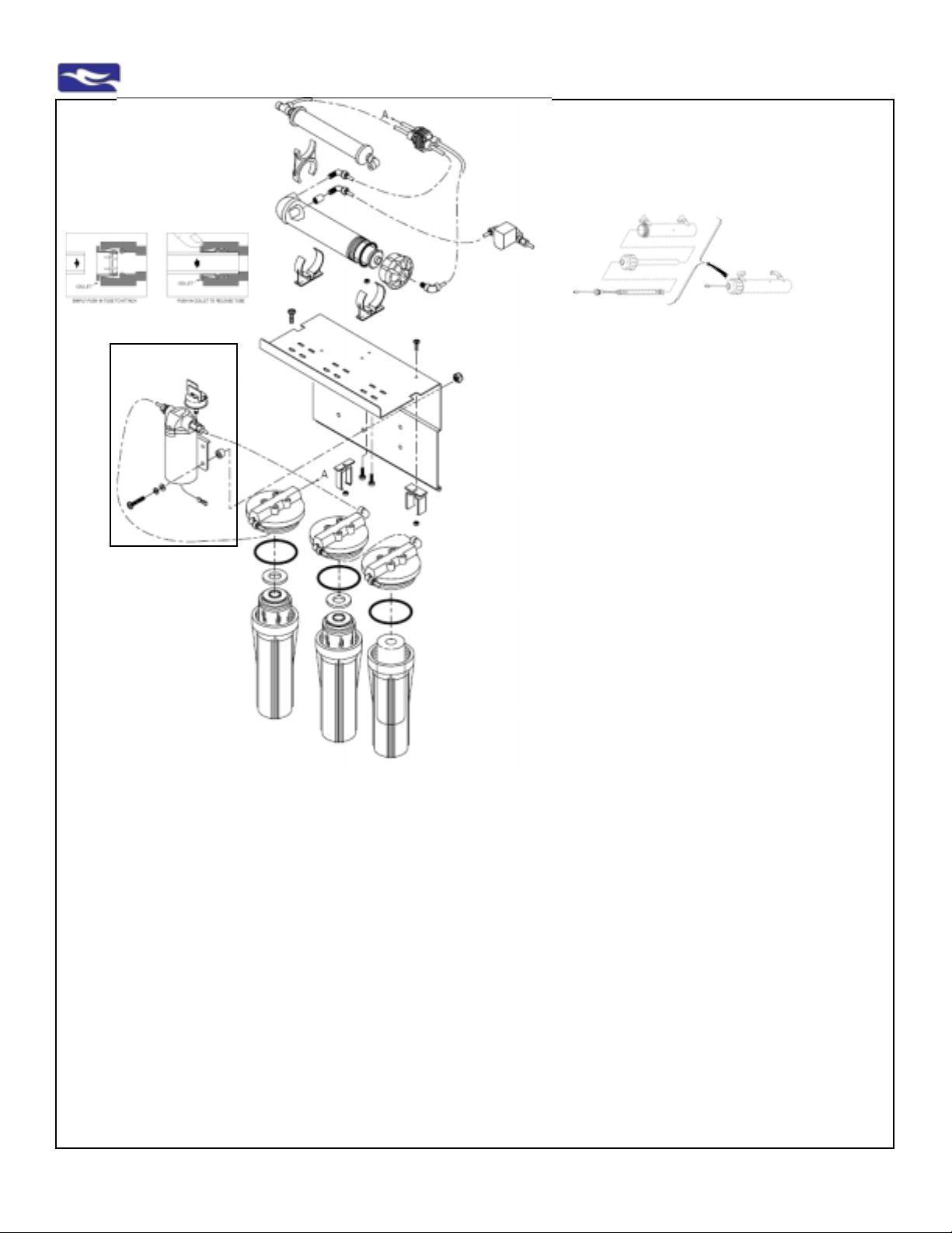
EWS, Inc. / Environmental Water Systems
4.2-35
illustrated quick
connect fitting
and proper tubing
connection
Optional:
Booster Pump
9
28
24
7
30
31
18
5, 6
9
Five-Stage Reverse Osmosis
Schematic, Parts: Shown with Booster Pump Option
for illustration purposes only
12
8
1
14
29
13
13
8
Optional: UV Disinfection Moduleshown below
92
93
94
95 95
91
31 Double Clips not shown with this UV illustration
10
9
9
9
9
28
9
32
28
4
3
3
3
Ref. No.
1
3
4
5
6
7
8
9
10
10a
12
13
14
18
24
25
28
29
30
31
32
20
21
22
23
Part No.
h-membrane
h-filter
93023
fc-rsr-wh
fc-rsr-gy
fc-ro-svl-t
CI480821W
CI480822W
ro-brkt-5
ro-brkt-5-bp
PI480821S
h-m-clip
TFC-RO
ro-rsr-tfc
UDF10HP
PI010822S
h-f-o-ring
020-MVH-0
IL-210-C
PPC212W
OCB
Not Shown
t-blk-drain
t-blue
t-orange
t-yellow
Description
M/H; STRAIGHT PORT
#10 SL WHITE/WHITE WO/PR
PX05-9 7/8" 5M SED CARTRIDGE
JG 1/4" X 1/8" M COMM - White on RSR
JG 1/4" X 1/8" CONN - Grey on RSR
JG 1/4" SWIVEL BRANCH T
JG 1/4" X 1/8" FIXED ELBOW; WHITE
JG 1/4" X 1/4" FIXED ELBOW; WHITE
.090 ALUM BRACKET; POWDER COAT
Substitute bracket with Booster Pump option
JG 1/4" X 1/8" FIXED ELB
WHITE 2" FAST CLIP PPC202W
TFC MEMBRANE
150 GPD RSR FLOW CONTROL RSR100-150
10" GAC CARTRIDGE
1/4" X 1/4" MALE CONNECTOR
HOUSING O-RING FH4000
O-RING KIT
10" T40 CARBON INLINE; 1/4" FNPT
DOUBLE CLIP - WHITE
HIGH-DENSITY GAC PREFIL TER
See Tubing Connections, Pg. 13-14
1/4" PE TUBING; 60"; BK-P , DRAIN
1/4" PE TUBING; 60"; BL-P, OUTPUT
1/4" PE TUBING; 60"; OR-P , INPUT
1/4" PE TUBING; 60"; YL-P , T ANK
Path of Water Flow through System
from inlet water supply
1 through Sediment (93023)
1a through Booster Pump (if applicable)
2 through Prefilter (OCB) then
3 through Membrane (TFC-RO) then
3a through UV Module (if applicable)
into Storage Tank until needed
When water is needed
water flows from Storage Tank
4 through Postfilter (in-line, IL210C) then
5 through 2nd Postfilter (UDF10HP) then
through dispenser or into another
device (if applicable)
2
15
11
19
16
17
26
27
---
Option
91
92
93
94
95
--31
Not Shown
ro-tank 03.2
ro-tank valve
Not Shown
ro-clamp kit
Not Shown
STV-2
Not Shown
fd-ch-wh
fd-ag-wh
PI011222S
t-blk-gap
WRENCH
See Above
H-UV
n/a
n/a
UST-200 RL
fc-uv-jaco
Not Shown
POU-UV-E68
PPC212W
See Storage Tank, Pg. 11
RO102W 3.2 GALLON T ANK 141S152
1/4" FQC X 1/4" FPT EL-V AL VE PPSV500822W
See Drain, Pg 12
DRAIN CONNECTOR; 1/4" FPT PDC602F
See Inlet Water Connections, Pgs 8-9
SELF PIERCING SADDLE VAL VE
See Dispenser/Faucet, Pgs. 4-7
LONG REACH FAUCET ; WH/WH QMP-102W
AIR GAP FAUCET ADAPTER
3/8" X 1/4" MALE CONECTOR-Air Gap Kit
3/8" PE TUBING BLACK - Air Gap Kit
SPANNER WRENCH FOR FIL TER HOUSINGS
UV Disinfection Module Shown Separately
FULLY ASSEMBLED MODULE ON T OP OF UNIT
UV MODULE HOUSING
UV CAP , O-RING AND GLASS SLEEVE
UV LAMP AND LAMP CORD
JACO 1/4"COMPRESSION X 3/8" FIXED ELBOW
UV ELECTRIC 24 V TRANSFORMER
DOUBLE CLIP - WHITE
www.EWSWATER.com office: 702-256-8182 (m-f; 8:30-4:30, pst) fax: 702-256-3744 [email protected]
Page 36

4.2-36
EWS, Inc. / Environmental Water Systems
Limited Warranty
Notification:
This warranty is referenced by EWS, Inc. in all literature, addressed in General T erms and S tandard Conditions of Sale,
and is published in its entirety in all EWS, Inc. product manuals, websites, and in all service guides supplied with all
product.
Limited Warranty:
EWS, Inc., a Nevada corporation, hereby warrants all products to the original consumer purchaser to be free from
defects in material and workmanship as stated in the following paragraphs:
• All residential point of use: countertop filtration, in-line filtration, undercounter drinking water filtration, shower filtration,
residential reverse osmosis, and point of entry pre-sediment units or systems for one year from date of purchase.
• All residential point of entry: pH decreasing and softener (resin and ion-exchange) systems, Environmental (EWS)
Water Systems, pyrolox units, CWL whole-home (filtration media) systems, pH increasing reagent (sacrificial media)
units for 10 years on the tank and riser , 10 years on the ICN conditioner(s) (if applicable) and 3 years on the valve head
from date of purchase.
• All commercial systems: Dependent on specification and application, please consult with EWS, Inc. upon specifica-
tion.
• All filtration medias, resins, cartridges, uv lamps, and/or membranes are not covered by any warranty. Filter media,
resin, cartridge, uv lamp, and/or membrane replacement or maintenance schedule will vary and must be replaced, as
necessary , as determined by usage and local water conditions.
Product performance may vary based on local water conditions, proper product specification and application, proper
plumbing application, setup, installation, startup, maintenance and/or usage. To ensure proper operation, follow all
setup, installation, start-up and maintenance procedures as detailed in all service guides.
Not intended for use where water is microbiologically unsafe or with water of unknown quality without adequate disinfection before or after unit(s). The contaminants or other substances removed or reduced by these and any other water
filtration or treatment devices are not necessarily in your water. T o confirm the presence of any primary and secondary
contaminants, have your water supply completely analyzed by an independent and approved facility or if applicable,
contact your local water utility for information. Aesthetic, non-health related, or constituent s without set federal st andards may be part of water testing but are insufficient to determine proper application of any water filtration or treatment
device.
EWS, Inc. will replace, free of charge, during the warranty period, any part which proves defective in material and/or
workmanship under proper product and plumbing specification and application, normal and proper installation, use,
service and proper care as published in detail in all service guides included with product. Labor charges are excluded
from any warranty service or repair and are not the responsibility of EWS, Inc. Shipping charges may apply to delivered
replacement parts or materials. Charges may also apply for the cost of any replacement media, resin, cartridges, uv
lamp and/or membrane from any warranty service or repair. Information can be obt ained at any time through a local
dealer, distributor , representative or direct from EWS, Inc. and/or on-line at; www .ewswater.com or www .ewswater .com/
techandspec.html. Replacement parts can be obtained from your local dealer , distributor or contractor .
This warranty is the exclusive warranty granted by EWS, Inc. and is in lieu of all other warranties of merchantability and
fitness for a particular purpose and is further limited to defective parts replacement only . Labor charges and/or damage
incurred in setup, installation, and startup, or repair , or replacement, as well as, incidental and consequential damages
connected there with, are excluded, and are not the responsibility of, and will not be paid by EWS, Inc.
This warranty is void for any damages due to improper product and/or plumbing specification and/or application, misuse,
abuse, neglect, accident, acts of nature, action of any military or civil authorities, improper handling and transportation,
or improper setup, installation, and/or startup, or any violation of instructions furnished by EWS, Inc., or any replacement parts other than genuine parts or replacements supplied by EWS, Inc.
This warranty is not a warranty of merchantability , fitness, taste, aesthetics, and/or performance that may be subject to
improper product and/or plumbing specification and/or application, misuse, abuse, neglect, accident, acts of nature,
action of any military or civil authorities, improper handling and transportation, or improper setup, installation, and/or
startup, or any violation of instructions furnished by EWS, Inc.
This warranty is not a warranty of merchantability , fitness, taste, aesthetics, and/or performance that may be personal
and of subjective opinion and that does not relate to the performance of any system.
www.EWSWATER.com office: 702-256-8182 (m-f; 8:30-4:30, pst) fax: 702-256-3744 [email protected]
Page 37

EWS, Inc. / Environmental Water Systems
4.2-37
Limited Warranty - Original Purchaser ’s Responsibility
Keep a record of the purchase receipt and/or installation receipt. Purchaser is required fill out warranty registration form(s)
on applicable product(s) and register all product by either on-line @ www.ewswater .com, telephone, postal delivery , fax, email (either [email protected] or information provided to customerservice@ewswater .com). Failure to do so voids
the warranty . EWS, Inc. does not sell, show or make available any information on any consumer in our database. This
database is to ensure, if needed, proper warranty service, and good customer service for years to come. Please see our
privacy policy published in our website at www.ewswater .com.
Know Y our W ater:
• If on a municipal system, large or small, it is your right as a consumer to have access to the most recent test results and
to expect adherence to federal guidelines, as well as any state or local requirements. Any problems should be reported to
the appropriate agencies. Please acquire those municipal test results to become an informed consumer .
• If on an individual well, have your water completely and independently tested. Local code may require a simple test for
coliform bacteria to approve a well, however you may be unaware of potential problems for you and/or your home. A local
water salesman is looking to close a sale and is going to test for hardness minerals and a few simple and obvious issues,
which may or may not be contamination problems. Their solution is almost always the same and yet may provide no
resolution to any true problems. Obtain our “Guide for the Private Well Owner” on our website; www .ewswater .com (under
Service Guides). Review our section on well water testing and applications in our complete catalog with your local
distributor , dealer, or our representative or visit our website.
• WARNING:
Some restrictions apply to the use of softeners. Contact your local municipal water district or Gov't Agency. Brine
discharge is already restricted on, or may be a problem for, septic applications and waste water treatment facilities. Since
some states have already restricted softeners to metered valves to prevent excessive brine discharge, EWS, Inc. only
provides metered valving in its line of softeners.
Restrictions may also apply to hot-side only , salt-exchange tanks or services, or an outright ban. Local water dealers and
other organizations do not inform consumers of these issues and believe these rules are unenforcable. The consumer is
ultimately responsible.
Softeners may also provide warranty issues with pools and spas, certain other products and finishes. Softened water
should not be used for drinking, cooking, pets or plants and is usually bypassed or “looped away” from the cold side of the
kitchen sink. Reverse osmosis, which also has its drawbacks and issues with other products and materials, may be used
to remove the salt from the water that the softener put in at the kitchen sink, yet may be misapplied for the actual local
water conditions.
Any problems of water quality , or the fitness of any EWS, Inc. product that is associated with any mechanical, construction, application, installation, and/or environmental issue(s) (ie: flow rates, line pressure, piping materials, broken supply
lines, changing water conditions; well or municipal water quality , et. al.), known or unknown, of the home or facility will not
be considered by EWS, Inc. until such issue(s) have been resolved.
Responsibility for the proper product and/or plumbing specification, application and/or installation of any device manufactured by EWS, Inc. lies with the consumer, their builder contractor, plumbing sub-contractor and any other installer of
choice. Items do not specify and/or install themselves. EWS, Inc. has provided many sources to acquire information on
the proper application of systems and their installation prior to any purchase. EWS, Inc. manufactures a complete product
line of point of use water filtration systems and point of entry filtration, softening and/or conditioning systems and/or
appliances. EWS, Inc. and the distributors of EWS, Inc. will stand behind the warranties of materials and workmanship.
However, EWS, Inc. and the distributors of EWS, Inc. and the Environment al Water Systems Product Line do not bear any
responsibility for improper applications of product and/or improper installation. It is for this reason that EWS, Inc. provides
complete information on all product for your understanding, specification, application and selection, and proper plumbing
application and installation.
T o obtain warranty service support, cont act your local dealer or contractor from whom you obtained the product or contact
EWS, Inc., Customer Service, via phone, fax, or email.
www.EWSWATER.com office: 702-256-8182 (m-f; 8:30-4:30, pst) fax: 702-256-3744 [email protected]
Page 38
4.2-38
EWS, Inc. / Environmental Water Systems
PRICING POLICY
EWS, Inc. has a current, published, and widely distributed, Pricing Guide that contains suggested list prices for certain water filtration
and conditioning products ("Products") sold by EWS, Inc. ("Seller"). Seller assumes no obligation to sell to anyone any of the
Products listed herein, known or unknown, at any price.
This current Pricing Guide has been prepared for the convenience of Seller's distributors and their customers. The list prices
shown are guides only and do not purport to represent actual prices in any particular market and are not intended to interfere with the
right and responsibility of Seller's distributors to establish their own resale prices.
All current prices herein set forth supersede all prior lists and are subject to change without notice. Seller may also, from time
to time, change, modify, alter, improve and/or discontinue without notice the sale of any of the Products listed herein.
All seller's orders are accepted and delivered based upon the Terms and Conditions found on this Pricing Policy page, found in
this Pricing Guide, available in all Seller’s Product Manuals and reprinted on the reverse side of all invoices submitted and monthly
statements sent. Please read them carefully. They provide information that is important to Seller's distributors and their customers.
GENERAL TERMS AND STANDARD CONDITIONS OF SALE
Invoices are expressly limited to and made conditional upon the terms and conditions contained herein. Objection by Buyer to any
of the terms contained herein shall be deemed to have been waived (if not previously waived) if written notice of the objection is not
received by EWS, Inc. ("EI") within ten calendar days of the date of the first invoice or before part of the described goods are accepted
by Buyer, whichever occurs first. Any additional or different terms proposed by Buyer are rejected unless assented to in writing by EI.
1. PRICES: All prices are in U.S. dollars. Prices are subject to change without notice. Orders will be invoiced at prices
prevailing at time of shipment. All prices are F.O.B. our warehouse, Southern California and exclusive of any shipping, delivery,
packaging or handling charges that may apply.
2. TERMS OF PAYMENT: The terms of payment on approved accounts only shall be net thirty days in U.S. dollars from the date
of invoice to date of receipt of payment in our offices for all invoiced products whether partial or complete delivery of the product under
order. All past due accounts are subject to a charge of 11/2% per month (18% per annum) for each month or fraction of a month on
the unpaid balance.
3. TAXES: Prices do not include sales, use, excise or similar taxes. The amount of any present or future sales, use, excise
or other tax applicable to the sale or use of EI's products or equipment shall be paid by the Buyer unless the Buyer shall have provided
EI with a tax exemption certificate acceptable to taxing authorities.
4. ACCEPTANCE: All purchase orders are subject to acceptance by EI at its corporate offices in Las Vegas, Nevada and are
subject to these Standard Conditions of Sale, unless otherwise expressly provided.
5. SHIPMENTS: Delivery to carrier shall constitute delivery to customer. EI's responsibility terminates upon delivery in good
order to carrier. All goods are shipped at the customer's risk. Any claim for loss or damage in transit should be made promptly by
customer against carrier. These and other shipment terms are written clearly on the reverse side of all packing slips that accompany
all accepted shipments. All costs of freight, transportation, handling, in-route storage, certification and other documentation are to be
paid by Buyer. Any other terms will be issued to Buyer, in writing, with approved credit and an established EI/Buyer relationship.
6. DELAYS; FORCE MAJEURE: EI shall not be liable for delays in delivery of the goods or failure to deliver the goods caused,
in whole or in part, by inability to obtain transportation, equipment, or material, insurrection, fires, floods, storms, embargoes, action
of any military or civil authorities, whether legal or de facto, strikes, labor difficulties, lockouts, acts of God, or other similar or different
circumstances beyond the control of EI.
7. CANCELLATION: The Buyer may not cancel all or part of an order without verifiable notification to, and acceptance by EI.
8. RETURN OF MATERIALS: No Product may be returned to EI without written approval by a Company Officer. A restocking
charge of 25% will be assessed (45% if unit had been used) NO EXCEPTIONS. Product must be returned freight pre-paid, boxed
and in resale condition. EI will never take responsibility, under warranty or return, for improperly installed and/or misrepresented
units.
9. SELLER'S SECURITY INTEREST: EI shall retain a security interest in the goods sold hereunder until Buyer has paid in full
for such goods provided by EI in connection therewith and has performed all of Buyer's obligations under this contract.
10. COLLECTION: Buyer shall reimburse EI for all costs of collection, including reasonable attorney's fees, incurred by EI to
collect any monies owing under this contract. A $45.00 service charge will be invoiced on all returned checks.
11. WAIVER AND MODIFICATION: No waiver or modification of any of these Standard Conditions of Sale shall be effective
unless such waiver or modification is in writing and signed by an officer of the Company in Las Vegas, Nevada. In event any part of
these conditions be waived, or be held to be invalid by any competent court, the remainder shall continue in force and shall be
interpreted as if such waived or invalid part were not contained herein.
Published and Printed in the U.S.A.
EWS Inc./Environmental Water Systems
9101 W. Sahara Ave., Suite # 105-J8, Las Vegas, Nevada 89117
ph 702-256-8182, fx 702-256-3744 [email protected]
(formerly, Esbinco, Inc.) 9/94, rev: 9/02
ww w.ewswater.com
EWS, Inc. 06/83, 09/99, 01/03 memo_conditions_sale_EWS.p65
www.EWSWATER.com office: 702-256-8182 (m-f; 8:30-4:30, pst) fax: 702-256-3744 [email protected]
Page 39
EWS, Inc. / Environmental Water Systems
4.2-39
A Quick Reference of Systems and Combinations for Various Applications
EWS - The Leader in Whole Home Water Filtration
EWS Series - The Environmental Water System
Whole Home Water Filtration and Physical Conditioning
Filters all the water to the whole home and offers the consumer an alternative to harsh salt softening. EWS
conditioning causes a physical change in how naturally found calcium and magnesium minerals react in the
water and on surfaces. EWS keeps these minerals in the water for a pure, fresh taste while helping solve
those problems associated with hard water. The result: less spotting, easier clean up, and prevents scale
build-up in pipes and water heaters without the damaging effects of salts. No slippery feeling. No brine
discharge. The best combination of whole home filtration and the alternative to salts and softening. Required
or chosen upgrade options: Sink units for specific removal needs or concerns.
CWL Series - Whole Home Water Filtration Appliance
Great for filtration to the whole home of chlorinated water supplies, for drinking, cooking, showering, and bathing (great for
hair and skin) - all uses. Also used for non-chlorinated applications to safeguard water from VOC’s due to ground water
contamination. Use EWS Series to filter and physically condition water, if water hardness is an issue. Required or chosen
upgrade options: Point of use, drinking water system, or reverse osmosis for limited sink applications based on water
conditions or additional water concerns for drinking use.
EWS - The Complete Choice for Sink Filtration
Drinking Water Filtration Systems
Sink filtration product for oral intake, drinking, cooking, ice-making, etc., to protect consumer against known or
unknown water issues or concerns. FUGAC250 (“better”) for carbon block filtration of chlorine and VOC’s, lead,
and cysts. UU250 (“best”) for the additional safeguard from bacterial, viral, e-coli and microorganisms. No storage
tanks, no limited supply, and no wasted water associated with reverse osmosis systems.
Reverse Osmosis Systems
Sink filtration product for oral intake, drinking, cooking, ice-making, etc., to protect consumer against known or
unknown water issues or concerns. RU300 series for chlorinated municipal water. RU400 series for potable nonchlorinated, well or municipal supplies. RU500 series optional for harsh well water. Add UV module for the additional safeguard from bacterial, viral, e-coli and microorganisms. Be aware that RO has specific issues and
drawbacks (ie: wasted water, limited production, storage tank space, very aggressive water), and has specific
applications, making these systems widely misapplied. Select the product that’s right for you.
EWS - The Resource for Well Water Solutions
High Oxidation, Purity Media Systems
For the removal of iron, manganese and hydrogen sulfide. Installed at the point of entry, this is a removal of these problems, not
the trade-offs of ion-exchange. Automatic backwash with no brine discharge, no chemicals to add, and years between any
maintenance (media replacement) make these systems a must with wells having these pre-treatment issues.
Plus: pH Increasing Reagent or pH Decreasing Resin Systems, Pre-Sediment Filtration .......
Softeners
If water hardness is an issue, water softeners will soften the water through ion-exchange. This process substitutes
naturally found calcium and magnesium (hardness) minerals for sodium or potassium chloride (salts) and
filter the water. Water will spot less, wipe off easier, and prevent lime scale in pipes and water heaters. However,
restrictions on softeners due to brine discharge into your septic tank, salts, and wasted water are growing. Softeners
may also void warranties on other household products (ie: pools, spas, special finishes, etc.) Once softened, many
people do not like the slippery feeling of the water and reverse osmosis becomes necessary to remove the salt from
drinking water that the softener put in. If a softener is chosen, application on the hot side only is recommended. Ironically ,
we make some of the most efficient metered softeners in the industry. Consider on hardness above 20 grains and use
on excessive hardness above 30 grains. Use EWS Series as an alternative to filter and physically condition water below
30 grains.
Let us @ EWS, Inc. help you specify the correct product(s) for your application.
Know and understand your “city” water or have well water tested completely to specify the correct point of entry
system(s). Choose a filtration upgrade, at the sink, for consumption based on tested results, and/or additional needs or
concerns. A complete solution may use one or more products to satisfy an application.
www.EWSWATER.com office: 702-256-8182 (m-f; 8:30-4:30, pst) fax: 702-256-3744 [email protected]
does not
Page 40
4.2-40
Available on the Internet through Authorized Retail Web Distributors and
Available through Authorized Building Wholesale Supply Locations, Kitchen & Bath Showrooms
and Appliance Dealers, and their Building and Plumbing Contractors throughout the United S tates.
EWS, Inc. / Environmental Water Systems
The complete EWS, Inc./Environmental W ater System
product line from sink to whole-home, available through:
Business-to-Business E-Commerce Distributors.
EWS, INC.
Environmental Water Systems
A Complete Line of Water Filtration Product from Sink to Whole-Home
9101 W. Sahara Avenue #105-J8
Las Vegas, Nevada 89117
Telephone: 702-256-8182 Fax: 702-256-3744
E-Mail: [email protected]
Visit us on the web at: www.ewswater.com
This service guide and all materials herein is the property and copyright of EWS, Inc. 05/03: 051803
Providing information to help consumers.
All Product Proudly Manufactured and Assembled in the USA
www.EWSWATER.com office: 702-256-8182 (m-f; 8:30-4:30, pst) fax: 702-256-3744 [email protected]
 Loading...