

Environmental Water Systems RO4-UV User Manual
Since 1987
PRODUCT AND INSTALLATION MANUAL
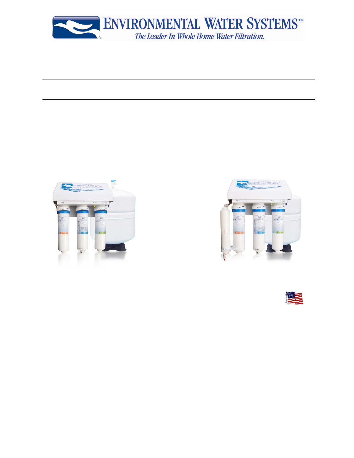
ESSENTIAL Reverse Osmosis Systems
Model Numbers:
1
RO3, RO3-UV
ALL FILTRATION PRODUCT PROUDLY MADE & ASSEMBLED IN THE USA
EWS, Inc./Environmental Water Systems
ofce. 702.256.8182
Monday - Friday, 8:30 am - 4:30 pm Pacic Standard Time
fax. 702.256.3744
www.ewswater.com
e-mail. customerservice@ewswater.com
Retain this Product & Installation Manual for Maintenance and Information
Please Register this Product - It is a Requirement for Warranty
www.ewswater.com O: 702.256.8182; M-F 8:30am-4:30pm PST E: customerservice@ewswater.com
RO4, RO4-UV
Revised 11/11

2
A Special Message to Our Customers,
EWS, Inc. and Environmental Water Systems would like to thank you for your consideration in selecting from our comprehensive list
of residential ltration and conditioning product. We recommend that you take the time to read the information that pertains to your
product as you begin to use it.
The information in this manual is designed to assist your installer to set-up, install and start-up your system properly. In addition,
the information contained in this manual is designed to provide the consumer, the most comprehensive information on this series of
product. Please contact us if you have any questions, comments or additions to the information provided.
Sincerely,
Customer Service at EWS, Inc.
Installation of the Filtration System - Please Read the Enclosed Information
Please take the time to familiarize yourself with the unit you are about to install. Locate the box with the lter top (head assembly) and
if applicable, the UV unit and the box with all the lter cartridges, tubing, angle stop valve and if applicable UV transformer.
You may need the following for proper installation:
• Teon tape • Work Gloves • Safely Glasses • Knife or scissors • Adjustable Wrench • Pliers • Screwdriver; straight & phillips • Drill & drill bits
WARNING: Verify that all components are included with the unit and were not lost, misplaced, or damaged in shipping or handling.
Any damage in shipping needs to be reported to the shipping company.
WARNING: Do not attempt to install this system using defective or damaged components. Check and inspect, inlet and outlet ttings
and any other connections on this system that might have been damaged during shipping and handling. Check all these components
again upon installation and start-up for any hidden issues. All plumbing should be done in accordance with all local plumbing codes. Water
Pressure: minimum 40psi, maximum 75psi. Water Temperature Range (cold supply only): not to exceed 100°F or below 40°F. Electrical
(if applicable): an uninterrupted a/c supply, (if applicable): make sure voltage supply is compatible with your unit prior to install
WARRANTY: Warranty Registration of this product is required to have a warranty. A proper installation and start-up will save you time,
money and hassles, and is also required for warranty purposes. Any issue as a result of improper application, set-up, installation and/or
start-up will void any warranty.
Table of Contents
Q&A for Reverse Osmosis water dispensers 3
Placement of the Supplied Dispenser 4
Installation of Dispenser with Air Gap 5
Installation of Dispenser without Air Gap 6
Supplied Professional Connection - Connection to sink cold side supply line 7
Placement or Locating the Essential RO System 8
Placement of the Storage tank 9
Drain Installation 10
Connections of Tubing from Supply, Dispenser, Storage Tank & Drain 11
System Start-up and Operation Procedures 12
Replacement of Filter Cartridges, Membrane & Replacement of UV Lamp (if applicable) 14
Correct Filters and How to Order Replacements 15
Maintenance Guide to the Essential RO System 16
Troubleshooting 17
Warranty 20
How to Select EWS Whole Home Water Filtration 21
RO3 and RO4 Product Tearsheets 22
Contact Information and Customer Service back cover
www.ewswater.com O: 702.256.8182; M-F 8:30am-4:30pm PST E: customerservice@ewswater.com

Dispenser/Faucet Q & A - Reverse Osmosis
Things to know:
1 - Spout pulls out from faucet body that’s why it swivels.
2 - Spout has 2 o-rings at base and is inserted completely into bottom of body to prevent leaking.
3 - Handle and tip can also be removed
Q: I do not want to drill any extra holes or use a separate dispenser/faucet - what can I do?
A: Nothing. Reverse osmosis systems are limited to a separate dispenser.
WARNING:
These systems manufacture a limited amount of water and therefore the connection to the cold side of your sink
faucet is an unavailable option. In addition, the water produced by a reverse osmosis system is aggressive and would
have adverse leaching effects on any other metals (ie: brass, copper) other than stainless steel.
Note:
This application or option is not applicable for reverse osmosis systems. Drinking water ltration systems are pass
through systems and will allow this option. There will be a diminishment in your ow rate to the cold side of the faucet
(kitchen faucet has a ow rate of up to 2.3 gallons per minute and the ltered water is delivered up to 1 gallon per
minute). To get ltered water you must be sure you have the faucet to the cold side only.
Q: I would like to use another dispenser/faucet?
A: Based on many styles and nishes, a consumer may have another dispenser they would like to use. No
problem, all these items have universal or industry standard ttings, or if not, can be easily adapted to t. Always
check with manufacturer for proper specications.
3
Note:
EWS, Inc. includes a standard chrome, long-reach, lead-free faucet with white tip, handle and optional air gap adaptor
(reverse osmosis systems only). Be aware - an air gap may be code and required with a dispenser/faucet installation.
Options: EWS provides the following options to match other items at an additional charge;
Change your white tip and handle to black
Change your white air gap adaptor to black
Change your faucet to the following nshes; satin nickel, polished nickel, polished brass, or oil
rubbed bronze (all with black tip, handle and air gap). Inquire with your local EWS, Inc. distributor,
contact an authorized internet distributor or visit us on the web
Q: Canweconnectthelteredwateruptootherdevices?
A: Yes, simply connect by a “T” connection, the ltered water line to any instant hot, chiller, ice-maker, refrigerator, etc. Regarding ow rate, be mindful of too many (3 or more) connections. Any length of total tubing in excess of
20 feet combined to tank, faucet, and all items will create issues with delivery rates**. See our Point of Entry, Whole
Home Appliances to lter all the xtures within the home.
WARNING:
Reverse osmosis may have warranty or restrictions with other devices, consult with other manufacturer’s product
information. Any length of total tubing in excess of 20 feet combined to tank, faucet, and all items will create issues
with delivery rates**.
Note:
**Tubing in excess of 20 feet is calculated by adding the length of yellow tubing from unit to tank and the blue tubing
from the “FAUCET” on unit to dispenser and/or another device(s). EWS, Inc. supplies 5 feet of each type of tubing.
Q: Do I need to use the air gap adaptor?
A: Yes, if local code requires that an air gap be used. Since the unit is both connected to a potable water
supply and a drain, some code requires an air gap to prevent cross-contamination, similar to all EWS point of entry
systems, a dishwaher and/or washer machines. Care has to be taken with this unit to make all the proper connections. Follow all local plumbing codes.
www.ewswater.com O: 702.256.8182; M-F 8:30am-4:30pm PST E: customerservice@ewswater.com

4
Placement or Locating Dispenser/Faucet - Reverse Osmosis
Step by step instructions to mount and secure the supplied dispenser/faucet
Professional Installation is Strongly Recommended
Step 1: Locate Faucet Parts Bag
Parts Included: faucet body with handle, faucet spout with tip, decorative washer, black rubber
washer, white beveled washer, lock washer, hex nut, 1/4” tube insert sleeve,
1/4” plastic compression ferrule, 1/4” compression nut
Optional Parts: at white washer (for use under decorative washer depending on hole/application)
air gap adaptor (white) for use with reverse osmosis air gap applications
Preferred - Select a standard sink location to mount the faucet.
It is recommended that the faucet be placed in a hole provided on most sinks similar to the holes used for a sprayer,
soap dispenser and/or dishwasher air gap. If the hole or space is unavailable, an alternative location will be required:
NON-AIR GAP: MINIMUM HOLE REQUIRED 1/2”, MAXIMUM 1 3/8”
AIR GAP: MINIMUM HOLE REQUIRED 1 1/4”, MAXIMUM 1 3/8”
Option A: On the sink. This option is to drill a new hole into the sink rim itself, if space allows.
Option B: On the countertop next to a sink. This option is to position the faucet spout in the correct location to
drain into the sink. This requires a clearance around the faucet both above and below the counter top. Use the supplied dispenser as a template or see the enclosed dispenser schematic and dis-
penser dimensions.
Prepare to drill the hole using the dispenser as a template.
• Sinks can be made of, but not limited to, stainless steel, copper, porcelain/steel, enamel/cast iron, man-made surfaces,
stone, concrete, and/or materials known or unknown at this time.
• Countertops can be made of, but not limited to, or be a combination of, natural stone, enamel, porcelain, concrete,
wood, metals and/or man-made materials known or unknown at this time.
CAUTION:
Please consult with the sink or countertop manufacture, supplier, fabricator, or installer for proper drilling techniques and methods.
EXTREME CARE MUST BE TAKEN IN DRILLING THE HOLE FOR ANY SURFACE. THE SURFACE MATERIALS OF
SINKS AND COUNTERTOPS CAN CHIP OR CRACK. THE MANUFACTURER ASSUMES NO RESPONSIBILITY FOR
ANY DAMAGE RESULTING FROM THIS INSTALLATION.
WARNING:
USE SAFETY GLASSES OR OTHER EYE PROTECTION WHEN GRINDING OR DRILLING TO PREVENT POSSIBLE
EYE INJURY DUE TO FLYING PARTICLES.
www.ewswater.com O: 702.256.8182; M-F 8:30am-4:30pm PST E: customerservice@ewswater.com
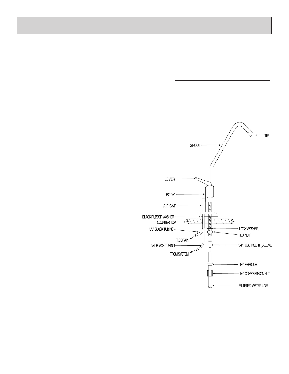
Installation of the Supplied Dispenser/Faucet with Air Gap
Step by step instructions to mount and secure the supplied dispenser/faucet
If using another faucet, please review the instructions included with that product**
***Other Air Gap connections can be found with
Drain Installation and Connection and System Interconnection instructions
5
Above the Surface
Step 2:
Place air gap to bottom of faucet body***
(optional: place at white washer under decorative washer)
Step 3:
Place black rubber washer below air gap
(or below optional at white washer)
Step 4:
Place faucet stem through hole and center
Below the Surface
Step 5:
Insert white beveled washer, bevel side up to
t snugly into a (1 3/8”) pre-drilled hole or at
side up depending on the application
Step 6:
Place lock washer on this white beveled washer
Step 7:
Spin hex nut onto faucet stem and
tighten hex nut and washers into place
Step 8:
Slide 1/4” compression nut (threads up)
onto 1/4” ltered line
Step 9:
Slide 1/4” plastic compression ferrule, long side
down onto ltered water tube. Ferrule will seat into
compression nut
Step 10:
Insert 1/4” tube insert sleeve into 1/4” ltered water line
Step 11:
Insert 1/4” blue (ltered water) tube into faucet stem. Leave
other end available for system interconnection
Step 12:
Thread 1/4” compression nut onto faucet stem and tighten
Enclosed Dispenser/Faucet Dimensions***
Height: from deck to top of dispenser 8”
from deck to tip of dispenser 6 1/4”
Reach: from center of dispenser to tip 6”
Hole: minimum required with air gap 1 1/4”
maximum 1 3/8”
CAUTION:Donotovertigthenttings
Note: Spout pulls out from faucet body and has 2 o-rings at base. Insert completely into bottom of faucet body to prevent
leaking. Spount swivels to direct water. Handle and tip can be removed. Handle can be locked up in open position.
** Other faucets check with specications. ***All dimensions are approximate.
www.ewswater.com O: 702.256.8182; M-F 8:30am-4:30pm PST E: customerservice@ewswater.com
6
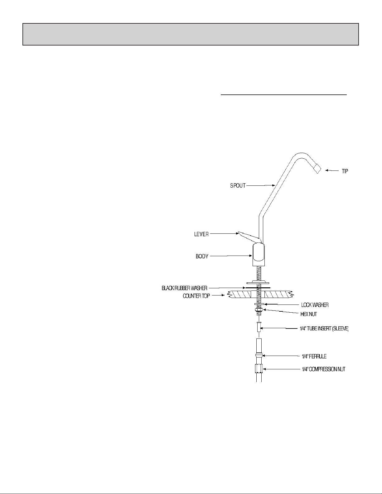
Installation of the Supplied Dispenser/Faucet without Air Gap
Step by step instructions to mount and secure the supplied dispenser/faucet
If using another faucet, please review the instructions included with that product**
Above the Surface
Step 2:
Place decorative washer to bottom of faucet body
(optional: place at white washer under decorative washer)
Step 3:
Place black rubber washer below decorative washer
(or below optional at white washer)
Step 4:
Place faucet stem through hole and center
Below the Surface
Step 5:
Insert white beveled washer, bevel side up to
t snugly into a (1 3/8”) pre-drilled hole or at
side up depending on the application
Step 6:
Place lock washer on this white beveled washer
Step 7:
Spin hex nut onto faucet stem and
tighten hex nut and washers into place
Enclosed Dispenser/Faucet Dimensions***
Height: from deck to top of dispenser 8”
from deck to tip of dispenser 6 1/4”
Reach: from center of dispenser to tip 6”
Hole: minimum required 1/2”
maximum 1 3/8”
Step 8:
Slide 1/4” compression nut (threads up)
onto 1/4” ltered line
Step 9:
Slide 1/4” plastic compression ferrule, long side
down onto ltered water tube. Ferrule will seat into
compression nut
Step 10:
Insert 1/4” tube insert sleeve into 1/4” ltered water line
Step 11:
Insert 1/4” blue (ltered water) tube into faucet stem. Leave
other end available for system interconnection
Step 12:
Thread 1/4” compression nut onto faucet stem and tighten
CAUTION:Donotovertigthenttings
Note: Spout pulls out from faucet body and has 2 o-rings at base. Insert completely into bottom of faucet body to prevent
leaking. Spount swivels to direct water. Handle and tip can be removed. Handle can be locked up in open position.
** Other faucets check with specications. ***All dimensions are approximate.
www.ewswater.com O: 702.256.8182; M-F 8:30am-4:30pm PST E: customerservice@ewswater.com
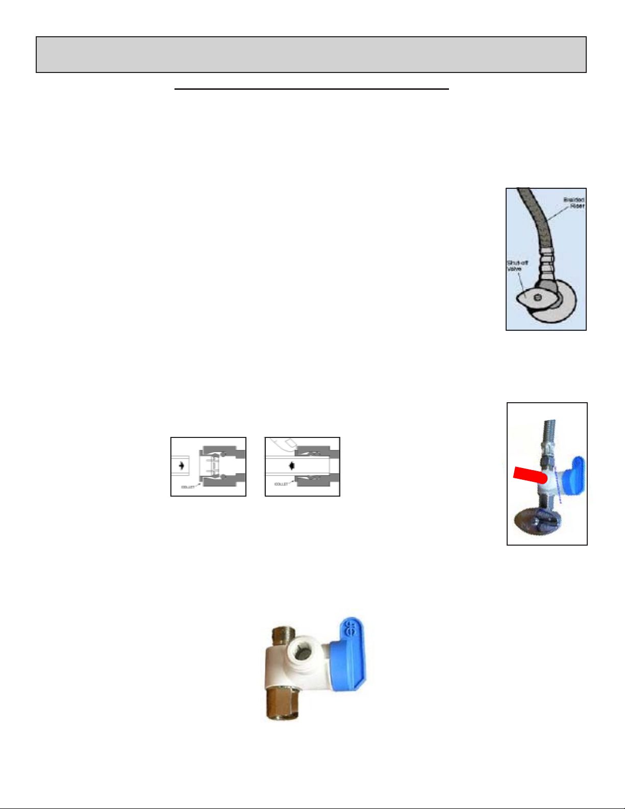
Supplied Professional Connection
Professional Installation is Strongly Recommended
The supplied tting is a John Guest Angle Stop Valve
which connects between the supply valve and riser to the main water supply line*.
Instructions from the bag containing the supplied connection
From parts bag locate: Angle Stop Valve
5 feet of red or orange 1/4” tubing (the proper tubing from the water supply to the system)
Step 1
BEST METHOD: Shut off the main water supply to the house and open the kitchen faucet to
relieve water pressure in the hard pipe. Once water stops owing from the kitchen faucet, shut off
the water supply at brass or chrome supply valve. This is the shut off valve for the cold water side
of the faucet under the sink (see illustration)
NOTE: Shutting the angle stop only, still leaves water in that pipe.
Step 2
Disconnect riser from brass or chrome supply valve.
This is the cold water line that feeds your existing kitchen faucet.
Step 3
Ensure that the sealing gasket is fully seated into the angle stop valve female thread.
Step 4
Install angle stop valve on supply valve.
Step 5
Connect the riser to the angle stop valve.
Step 6
Fully insert tubing into the quick connect tting on the side of the angle stop valve.
Pictured:
Example of shut off
valve and riser up to
the cold side of the
kitchen faucet typically
found under the sink
riser to cold side of the
kitchen faucet
7
To Insert: Make sure tubing has
an even edge than press tubing in
rmly and completely
Never Pull Tube Out To Remove
Push Collet In To Release
Cautions, Warnings and Inspections
To Test Fitting:
Give a Gentle “Tug” To Insure
Proper Connection
See All
CAUTION: USE ONLY COLD WATER LINE. NOT INTENDED FOR SUPPLY BY HOT WATER.
After complete installation of the system, open main water supply to the house and open all valves
and check for any leaks.
If needed, please refer to the John Guest Speedt Installation Guide and Technical Check List
for all other information or visit their website @ www.johnguest.com
Angle Stop Valve (ASVPP1LF)
NSF 51 Compliant
LEAD FREE - Meets AB1953
shut off to
water
tubing to
system
Pictured:
Example of shut off
valve and riser up to
the cold side of the
kitchen faucet with the
properly installed angle
stop valve
system
*Even though this connection can be used in over 90% of household applications, EWS, Inc. can not anticipate all the different locations, applications and
materials used by your builder and/or plumbing contractor or any pre-existing situations regarding your household or sink piping and cannot be responsible
for additional parts that may be necessary. Proper connection should meet all local codes. If necessary contact a qualied licensed plumber for another
part or method to properly install this system.
www.ewswater.com O: 702.256.8182; M-F 8:30am-4:30pm PST E: customerservice@ewswater.com
8
Placement or Locating the Reverse Osmosis System
Simply place the water system on a level oor, cabinet bottom or horizontal surface.
Always assume for enough space for the system and the storage tank, and tubing to remove, move and/or adjust
for lter and membrane replacement and maintenance.
If mounting the system to a wall, cabinet side or other vertical surface, a minimum clearance of 4” will be required to allow for lter replacement. Please see the following procedures:
Step 1
All lter cartridges and membrane for the system are included. For Model #s RO3-UV & RO4-UV only, UV Lamp and
Housing are pre-installed.
Locate lter cartridges and single membrane (Blue label with drain connection at bottom):
Starting from the left or “FEED” side, Stage 1 insert the Orange pre-lter, next (the middle) Stage 2 insert the Blue RO
membrane (note drain connection at bottom) and lastly Stage 3 insert Green post-lter.
NOTE: Water ows from Left (Labeled: FEED) to Right (Labeled FAUCET).
In order by color: from Left to Right: Orange, Blue, Green
Applicable for Model #’s RO4 & RO4-UV, 4-Stage units only:
Inline 5 micron pre-sediment lter is clipped onto the Orange pre-lter cartridge inserted into Stage 1.
WARNING: PLACING FILTERS AND MEMBRANE IN THE WRONG ORDER WILL ADVERSELY EFFECT THE
OPERATION OF THE RO SYSTEM
NOTE: Inserting the all cartridges:
At the blue top of each cartridge nd the side with two (2) notches. Line the notches up and insert cartridge into the lter
head assembly. Once cartridge is fully inserted into the head turn clockwise and completely lock into position.
Step 2 Once lter system has been fully assembled, mark pilot holes using the bracket as a template.
Step 3 Using a drill bit or punch, drill a hole or punch as a starter hole to catch the mounting screws.
WARNING: ALTERNATIVE FASTENING METHOD MAY BE REQUIRED FOR PLASTER BOARD, PARTICLE BOARD
OR SIMILAR MATERIAL INSTALLATION. USE SAFETY GLASSES OR OTHER EYE PROTECTION TO PREVENT
POSSIBLE EYE INJURY DUE TO FLYING PARTICLES.
Step 4 Set mounting screws (provided) with screw driver. Leave a 1/4” gap between the screw head and mounting
surface to allow the bracket to slide on easily.
Step 5 Slide the bracket over the screws and hang the unit. Make sure unit is level.
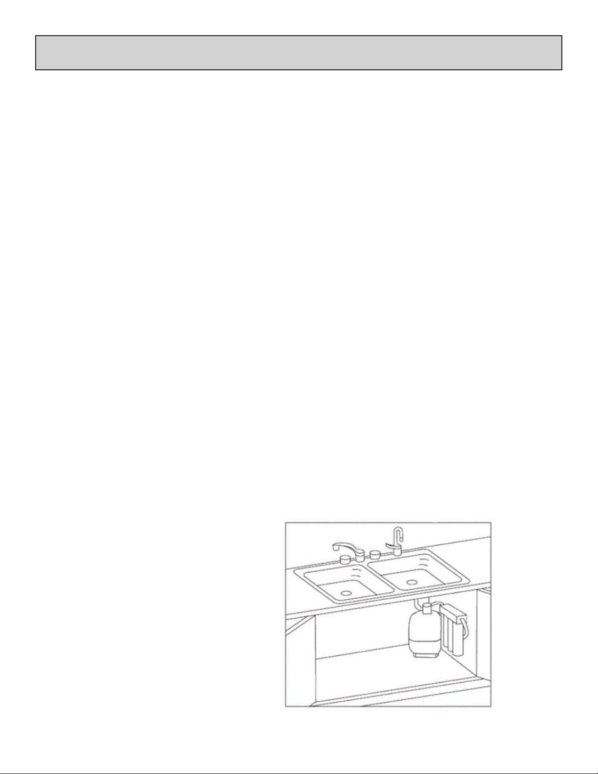
Helpful Hint:
Take a note of the Model # for the
Kitchen Faucet
Dispenser/Faucet of
ltered water
required warranty registration of this
unit. This Service Guide will come in
very handy when it’s time for lter replacement and restarting your reverse
osmosis system.
Please Note:
Storage Tank on oor
Water flows from Left (Labeled:
FEED) to Right (Labeled FAUCET)
Unit Mounted to Wall (option shown) or
Placed on level oor
In order by color from Left to Right:
Orange, Blue, Green
strictly for illustration purposes only
www.ewswater.com O: 702.256.8182; M-F 8:30am-4:30pm PST E: customerservice@ewswater.com
Inlet from
Cold
Inlet/Supply
Connection
(angle stop
not shown)
 Loading...