

Environmental Water Systems EWS 1354-2-P User Manual
EWS, Inc. / Environmental Water Systems
Care and Use Manual
T ank Series Appliances
Information Provided for the Proper Set-Up, Installation and
Start-Up of the following Appliances:
EWS Series of Whole Home Filtration and Physical Conditioning:
EWS-1054, EWS-1354, EWS-1354-HF, EWS1354-11/2”
CWL Series of Whole Home Filtration:
CWL-1035 L TD, CWL-1054, CWL-1354, CWL-1354-HF, CWL-1354-11/2”
Iron Removal Series:
EWS-1054-P, EWS-1354-1 1/2”-P
4.4-1
ALL PRODUCT PROUDLY MANUFACTURED AND ASSEMBLED IN THE USA
To the Installer: Please Read and Leave this Owner’s Manual with the Unit or the Consumer
To the Consumer: Retain this Care & Use Manual for Product Registration and Future Reference
www.EWSWATER.com

4.4-2
EWS, Inc. / Environmental Water Systems
IF YOU ONLY READ ONE PAGE IN THIS MANUAL - THIS IS IT !!!
INSTALLATION SUMMARY - 12 STEPS
Step 1:
Locate the following: Main Water Supply Line, Drain Access, Electrical Outlet and Clearances.
Step 2:
Check the incoming Water Pressure. Install a pressure regulator (PR V) if the water pressure exceeds or can surge above 75 PSI.
Step 3:
Place the tank where you want to install the unit, making sure the tank is level and on a firm base,
noting the clearances necessary to complete the installation. Can go anywhere, see details.
Step 4:
Since handling and moving the unit may loosen the valve head - make sure to Check and Tighten
V alve Head on the T ank. Hand Tighten the V alve Head in a Clockwise Direction. Make sure tank
cover , if applicable does not interfere or cut into the connection.
Step 5:
Identify Water Main Supply and plumb inlet (supply) and outlet (filtered) into the unit following the
directional arrows molded onto the valve body . Plumb the unit with the bypass and the male yoke
included, or for larger valved units, a bypass must be plumbed. Do not cross-connect or plumb
backwards. See detailed installation schematics and the helpful information in this manual.
Step 6:
Connect a backwash drain line (1/2” or 3/4”) based on application and an air gap.
Step 7:
Partially Open Inlet V alve Only . Fill Tank Slowly . Once tank is filled, completely open inlet valve.
Keep outlet valve closed. (Larger valved units, keep plumbed bypass valve closed).
Step 8:
Plug the unit into an electrical outlet. Be sure the outlet is dedicated and unswitched.
An outlet that cannot be turned “on” or “off.”
Step 9:
Set the time of day on the valve display .
Step 10:
Backwash and Flush the system properly until the drain water runs clear.
Step 11:
Open Outlet V alve slowly (Larger valved units, keep plumbed bypass valve closed).
Step 12:
Run hot/cold water throughout the home (at every tap) to flush pipes and water heaters to
prepare unit for usage. Y ou are done.
www.EWSWATER.com

EWS, Inc. / Environmental Water Systems
4.4-3
GENERAL INFORMATION AND PRE-INSTALLATION CHECKLIST
Verify: All components are included with the unit and were not damaged in shipping.
Caution: Do not attempt to install any system using defective or damaged components. Do not install any
system that has been misapplied.
Warning: When drilling or cutting, use protective eyewear to prevent possible eye injury due to flying objects.
When using an open flame and/or hot materials, take the necessary precautions for you and the
environment to prevent burns, burning and/or fires.
Water Pressure and Flow Rate:
A minimum of 35 PSI (40 PSI for Iron units) and 8 GPM (12 GPM for 1354 Iron units) is required for backwash
valve to operate effectively. Water pressure not to exceed or to surge in excess of a maximum of 75 PSI for
the system. Unsure of pressure or it’s ability to surge? A pressure reducing valve (PRV) becomes an insurance policy and is recommended for this and many other products that limit high pressure in your home.
Water Temperature Range:
Feed water temperature not to exceed 110°F or be allowed to go below 40°F. Protect unit from exceeding
high temperatures and never allow unit, its’ drain line and any water to freeze.
Electrical:
An uninterrupted alternating current (A/C) supply is required. Please make sure your voltage supply is compatible with your unit before installation.
Existing Plumbing:
Condition of existing plumbing should be free from lime and iron buildup. Piping that is built up heavily and
clogged with lime and/or iron should be replaced. Problem with iron? Our separate iron filter unit should be
installed ahead of any other unit. Old galvinized or combinations of plumbing materials can cause water
issues and conditions.
Location of Tank, Drain and Electrical:
Units can be installed, almost anywhere. Inside or outside. However, use your common sense. Valves may
be water resistant, not water proof. Protect any system from the elements. Review issues on water flow
rates and pressure, and environmental and water temperature ranges. The tank should have access to the
supply water, provide filtered water to the home, be located close to a clean working drain, have an electrical
outlet available, and be connected according to all local plumbing codes.
By-Pass Valves:
Always provide for the installation of a bypass valve, if unit (with larger valves) is not equipped with one.
Drain Connection:
Nominal drain line and drain size on 1054/1354 (non-iron) units should be a minimum of 1/2”. Backwash flow
rates of 7 GPM (1354 units) with drain line exceeding 20’ in length require 3/4” line and drain. Larger valves
require 3/4” line and drain. Install, non-restrictive, check valve in drain line, if drain water is expected to flow
over 5’ above the height of the drain port. Never restrict the backwash drain water flow .Teflon tape is the only
sealant to be used on the drain fitting.
All plumbing should be done in accordance with all local plumbing codes.
Unsure of the specifics?
All the information that you may need is in this product manual and available on the web.
Identify the unit you are installing and follow the detailed, Set-Up, Installation and S tart-Up of that unit.
WARNING: IMPROPER INSTALLA TION WILL RESULT IN THE VOIDING OF ANY WARRANTY .
www.EWSWATER.com
4.4-4
EWS, Inc. / Environmental Water Systems
Set-Up and Installation:
CWL-1035 LTD, CWL-1054, CWL-1354; EWS-1054, EWS-1354
DIMENSIONS OF UNITS TO BE INSTALLED:
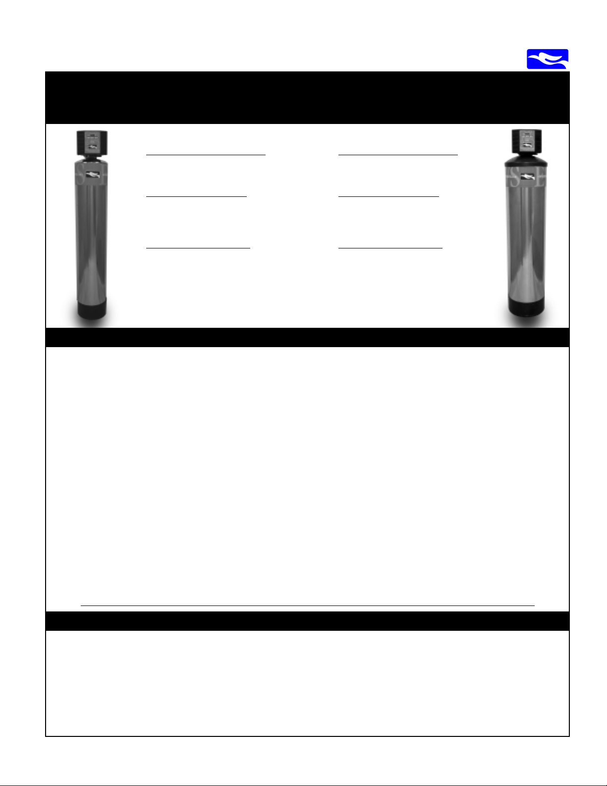
CWL-1054: or EWS-1054:
Service Line Size: 3/4” - 1”
Flow Rate: up to 15 gpm
Drain Line Size: min: 1/2”
Installed Dimensions:
Height: 62 1/2”; Width: 10”
Dry Weight: est: 105 lbs.
Inlet/Outlet Height: 56 1/4”
Drain Port Height: 57 1/2”
Plumbing Clearances:
Minimum of 18” from front of
unit to back wall for plumbing
Drain Flow: up to 4 gpm
Discharge:up to 18-26 gallons
Bypass and male threaded
1” MNPT yoke (included)
must be installed with valve
1 - PREPARE FOR INST ALLA TION:
Check the Following: Main Water Supply Line, Drain Access, Electrical Outlet, and Clearances to comlepte the install.
Location of Tank: Units can be installed, almost anywhere. Inside or outside. However, use your common sense. Valves may be
water resistant, not water proof. Protect any system from the elements. Review issues on water flow rates and pressure, and envi ronmental and water temperature ranges. The tank should have access to the supply water, provide filtered water to the home, be
located close to a clean working drain, have an electrical outlet available, and be connected according to all local plumbing codes.
Water Temperature Range: Feed water temperature not to exceed 110°F or be allowed to go below 40°F. Protect unit from
exceeding high temperatures and direct sunlight, and never allow unit, the drain line and any water to freeze.
Electrical: An uninterrupted alternating current (A/C) supply is required. The system is ideally located within 4-6 feet of a 110 volt
outlet to allow the unit to be plugged in. A 24 volt motor and transformer is available for longer electrical runs (use 10 -2 regular
lamp gauge wire). The 24 volt transformer must be located inside.
Existing Plumbing: Condition of existing plumbing should be free from lime and iron buildup. Piping that is built up heavily and
clogged with lime and/or iron should be replaced. Problem with iron? Our separate iron filter unit should be installed ahead of
any other unit. Old galvinized or combinations of plumbing materials can cause water issues and conditions.
Drain Connection: Nominal drain line and drain size should be a minimum of 1/2”. **Backwash flow rates of 7 GPM (1354 units) with
drain line exceeding 20’ in length require 3/4” line and drain. Install, non-restrictive, check valve in drain line, if drain water is expected
to flow over 5’ above the height of the drain port. Never restrict the backwash drain water flow .Teflon tape is the only sealant to be used
on the drain fitting.
Check Incoming Water Pressure and Flow Rates: A minimum of 35 PSI and 8 GPM is required for backwash valve to operate
effectively . W ater pressure not to exceed or to surge in excess of a maximum of 75 PSI for the system. Unsure of pressure or it’s ability
to surge? A pressure reducing valve (PRV), or limiting pressure to 75 PSI is recommended for this and many other kitchen and bath
products in your home. Automatic valve is rated for 100 PSI and the t ank is rated for 150 PSI, however the overall system w ith various
connections has limitations to excessive pressure. Water pressure measuring 75 PSI during the day may surge to over 100 PSI at
night when the automatic backwash occurs.
Install (often required by code) a pressure regulator (PRV) if the water pressure exceeds or can surge above 75 PSI.
CWL-1354: or EWS-1354:
Service Line Size: 3/4” - 1”
Flow Rate: up to 15 gpm
Drain Line Size: min: 1/2”**
Installed Dimensions:
Height: 63”; Width: 13”
Dry Weight: est: 135 lbs.
Inlet/Outlet Height: 56 3/4”
Drain Port Height: 58”
Plumbing Clearances:
Minimum of 18” from front of
unit to back wall for plumbing
Drain Flow: up to 7 gpm
Discharge:up to 22-38 gallons
Bypass and male threaded
1” MNPT yoke (included)
must be installed with valve
2 - UNBOX UNIT : CHECK T ANK AND V AL VE AND LOCA TE BYP ASS AND MALE YOKE:
1) PLACE THE T ANK WHERE YOU WANT T O INST ALL THE UNIT .
•Make sure the tank is level and on a firm base. Black bases on tanks are glued-on and self-leveling. If necessary, lift tank - tap
base to floor - on the bottom side, in order to level unit. Take note of the clearances necessary to complete the installation.
2) CHECK AND TIGHTEN V AL VE HEAD ON THE T ANK.
•Hand Tighten the Valve Head in a Clockwise Direction. Make sure the stainless tank cover or plastic dome (1354 units) does
not interfere or cut into the connections. Stainless covers are non-functional, if “dinged” in handling, turn to good side.
3) CONNECT BYP ASS VA LVE AND MALE YOKE TO V AL VE HEAD.
•Make sure bypass valves are facing up. Keep bypass valve level (horizontal). Do not put, upward or downward, pressure on
bypass valve, this will not allow nipples and o-rings to seat squarely and completely.
www.EWSWATER.com
EWS, Inc. / Environmental Water Systems
3 - PLUMBING LINE CONNECTIONS:
1) IDENTIFY THE MAIN W ATER SUPPL Y.
•Do Not Assume. You may have to perform “the old bucket test” to determine where the water is coming from.
•Make sure the whole facility is on the line. Some cold water lines (kitchen, island, wet bar sinks, refrigerators, ice-makers)
may have been plumbed separately, if previously plumbed for softened (salts) water. You may have to recapture those
lines by replumbing that manifold. Or, capture the main water supply before the bypassed or “looped” away lines, usually
found at, or after, the main water shut off. However, some plumbing designs prevent this ideal installation. A sink (point of
use) filtration unit can be used for that missed location.
•Hose bibs are unnecessary to capture unless required by consumer. Irrigation (which should tee-off prior to the home’s
main water supply) uses a lot of water and this connection should be discouraged. It puts an unnecessary burden on the
unit and the media.
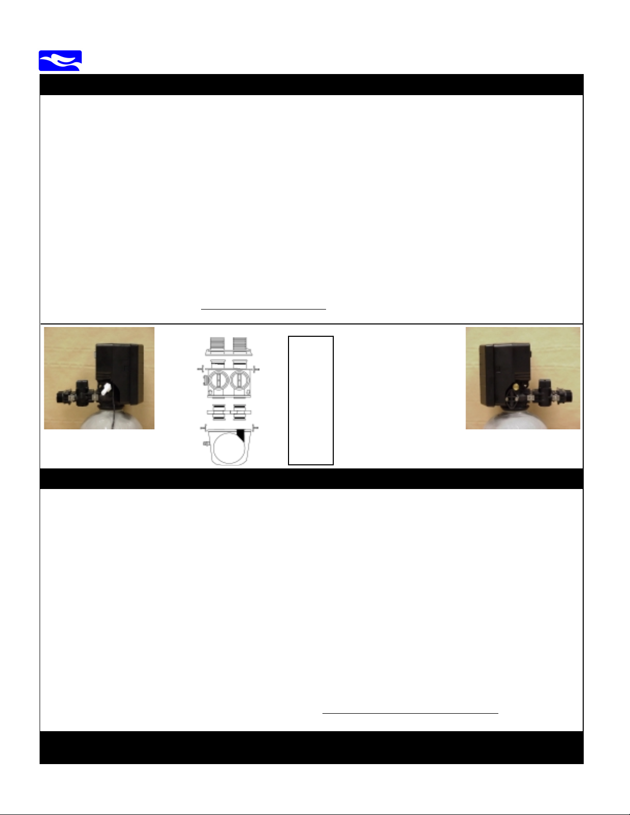
2) USING THE CONNECTED BYP ASS VAL VE AND 1” MALE NPT YOKE.
3) PLUMB INLET (supply) AND OUTLET (filtered) INTO THE UNIT.
•Follow the directional arrows molded onto the valve body and bypass. See pictures below for; top/front/back and left/right views
to prevent plumbing the unit backwards. Teflon tape is the only sealant to used on any of our fittings.
•NO Heat, No Torch; Leave at least 12” between the male yoke and any solder joints. Failure to do this could cause interior
damage. Consider flexible stainless (1”FNPT x 1”FNPT (3/4” if your application) and at least 18” in length) connected to copper
male adapters, or some other applicable connection - no heat, saves time, neat install, if applicable/code to your application.
4) WARNING: ONCE PLUMBED, DO NOT TURN ON W ATER, UNTIL YOU BEGIN START -UP PROCEDURES.
Note: If, recirculating pump on water heater, unplug pump before turning off water supply. Prevents damage to the pump motor.
top view:
outlet
side:
to the
home
filtered
left
Outlet (filtered) Side:
left side view of valve and drain
port with included drain adaptor,
bypass and male yoke
back:
side:
supply
from
main
right
front:
inlet
Yoke
1” MNPT
Dual
Port
Bypass
O-Ring
Connect
Valve
Head
Must use dual-port, full
flow, noryl bypass with
1” MNPT yoke.
•Shuts off water to/from
the unit
•No additional plumbing
for media replacement or
maintenance
•Less costly plumbing
installation, easier startups, non-corrosive
Inlet (supply) Side:
right side view of valve with
included bypass and male
yoke
4.4-5
4 - DRAIN CONNECTIONS:
1) LOCA TE DRAIN PORT ON THE LEFT (OUTLET) SIDE OF THE VAL VE HEAD.
•Inserted into drain port is a flow control housing. The flow control housing (male o-ringed insert x 1/2”FNPT) is a plastic disc,
held in by a retainer clip. The flow control housing has a flow washer which determines the flow rate in gpm from drain line.
2) DO NOT OVERTIGTHEN CONNECTIONS. IMPORT ANT TO READ THE FOLLOWING:
•Nominal drain line and drain size should be a minimum of 1/2”. **Backwash flow rates of 7 GPM (1354 units) with drain line
exceeding 20’ in length require 3/4” line and drain. Install, non-restrictive, check valve in drain line, if drain water is expected
to flow over 5’ above the height of the drain port. Never restrict the backwash drain water flow.
•Care must be taken when screwing in any connection to the flow control housing, not to crush piece and distort the flow
washer, crucial to the effective backwashing of the system. A drain adapter or hose barb has been supplied and is only
loosely connected. You may use this or any other applicable adaptor or connector depending on your drain line.
•Flexible tubing, poly tubing or any hose must be clamped (do not overtighten) and do not allow any tubing to kink.
•Hard piping of drain line: NO Heat, NO Torch, leave at least 12” between drain port and any solder joints - remember to
use a union (a quick disconnect feature) for future servicing applications. Therefore, the system will require no replumbing.
•Teflon tape is the only sealant to be used on any drain fitting.
3) LOCA TE A SUIT ABLE PLACE TO DRAIN.
•A suitable place to drain the backwash water must be available. Usually, into a drain or trap, or outside that has sufficient
percolation. You can be flexible or creative. Do not connect the backwash line to an air conditioning drain line. Do not fre eze.
•Air gap must be used, if connecting to a drain line or sewer trap, to prevent possible back siphoning into the tank.
•Backwash is a mechanical way of turning over the filtration media. The discharge is only water and not a brine. The water
discharge can go anywhere, may be used, or recycled, and does not have the legal restrictions or issues of brine discharge.
5 - GO TO SYSTEM START-UP PROCEDURES
www.EWSWATER.com
4.4-6
EWS, Inc. / Environmental Water Systems
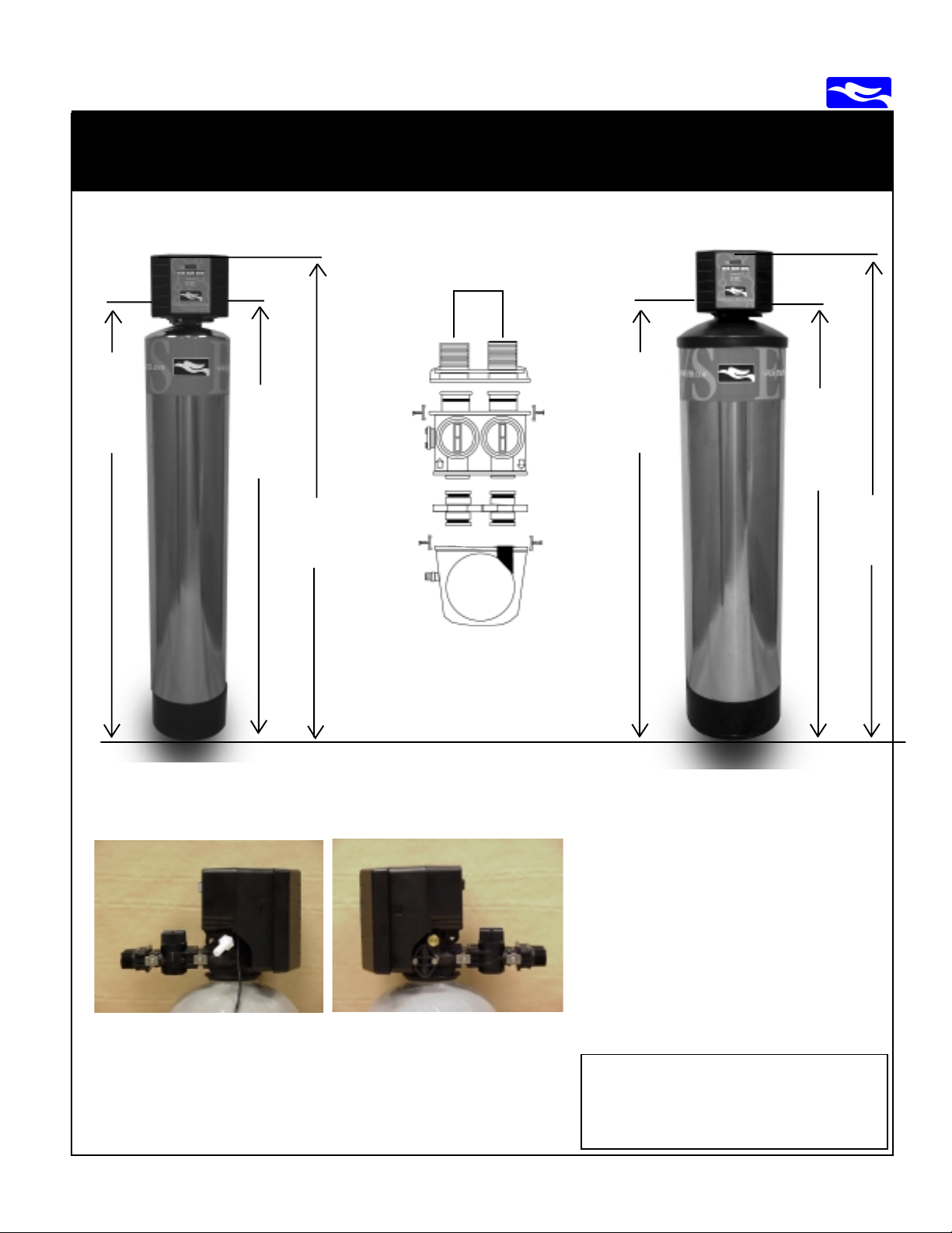
Set-Up and Installation Schematic:
CWL-1054, CWL-1354; EWS-1054, EWS-1354
DIMENSIONS OF UNITS TO BE INSTALLED:
CWL/EWS-1054
drain
line
57 1/2”
on center
water
inlet/outlet
56 1/4”
on center
overall
height
62 1/2”
outlet
side:
to the
home
filtered
left
back:
2”cc
front:
top view:
inlet
side:
supply
from
main
right
drain
line
58”
on center
CWL/EWS-1354
water
inlet/outlet
56 3/4”
on center
overall
height
63”
EWS-1354 comes with adaptor that allows for installation of valve on 13x54 tank and adds 1/2”
Due to tank and base variances overall dimensions +/- 1”
Must use the supplied
dual-port, full flow, noryl bypass
with 1” MNPT yoke.
•Shuts off water to/from the unit
•No additional plumbing for media
replacement or maintenance
•Less costly plumbing installation,
Outlet (filtered) Side:
left side view of valve
with included bypass,
drain adaptor, and
1” MNPT yoke
Inlet (supply) Side:
right side view of valve
with included bypass
and 1” MNPT yoke
www.EWSWATER.com
easier start-ups, non-corrosive
CWL-1035 LTD Not Pictured
Installed height approx 44”
valving, setup, install, and startup
exactly the same as these units.
 Loading...