

Page 1

EnGenius® X-TRA RANGE
®
ERB300H/ERB150H
Wireless-N HD Media Bridge & Range Extender
User Guide V1.0
Page 2

TABLE OF CONTENTS
0-I
TABLE OF CONTENTS
Product Overview
Product Overview 1-1
Hardware Features . . . . . . . . . . . . . . . . . . . . . . . . . . . . . . . . . . . . . . . . . . . . . . . . . . .1-1
Software Features . . . . . . . . . . . . . . . . . . . . . . . . . . . . . . . . . . . . . . . . . . . . . . . . . . . .1-2
Technical Specification . . . . . . . . . . . . . . . . . . . . . . . . . . . . . . . . . . . . . . . . . . . . . . . . . . . . . . . . . . . . . . . . .1-2
Physical Interface . . . . . . . . . . . . . . . . . . . . . . . . . . . . . . . . . . . . . . . . . . . . . . . . . . .1-2
Wireless Specification . . . . . . . . . . . . . . . . . . . . . . . . . . . . . . . . . . . . . . . . . . . . . . . .1-2
Hardware Specification . . . . . . . . . . . . . . . . . . . . . . . . . . . . . . . . . . . . . . . . . . . . . . .1-2
Package Contents 1-4
Product Layout 1-5
Installation
System Requirements 2-1
Wall Mounting 2-2
Page 3

TABLE OF CONTENTS
0-II
EnGenius Quick Start
Installing the Software 3-1
Setup Notes . . . . . . . . . . . . . . . . . . . . . . . . . . . . . . . . . . . . . . . . . . . . . . . . . . . . . . . .3-1
Installation . . . . . . . . . . . . . . . . . . . . . . . . . . . . . . . . . . . . . . . . . . . . . . . . . . . . . . . . .3-2
Connecting the Cables 3-3
Installation Setup Wizard
Setting Up the ERB300H/ERB150H 4-1
Using the ERB300H/ERB150H as a Range Extender . . . . . . . . . . . . . . . . . . . . . . . . . . . . .4-1
Using the ERB300H/ERB150H as a Media Entertainment Bridge . . . . . . . . . . . . . . . . . . . . . . . . . . . . . . . .4-4
Getting Started . . . . . . . . . . . . . . . . . . . . . . . . . . . . . . . . . . . . . . . . . . . . . . . . . . . .4-4
Setting Up the Media Bridge . . . . . . . . . . . . . . . . . . . . . . . . . . . . . . . . . . . . . . . . . . .4-4
Web Configuration
Logging In 5-1
Web Menus Overview 5-2
Universal Repeater Mode Menus . . . . . . . . . . . . . . . . . . . . . . . . . . . . . . . . . . . . . . . . . .5-2
Page 4

TABLE OF CONTENTS
0-III
System . . . . . . . . . . . . . . . . . . . . . . . . . . . . . . . . . . . . . . . . . . . . . . . . . . . . . . . . . .5-2
Wireless . . . . . . . . . . . . . . . . . . . . . . . . . . . . . . . . . . . . . . . . . . . . . . . . . . . . . . . . .5-3
Network . . . . . . . . . . . . . . . . . . . . . . . . . . . . . . . . . . . . . . . . . . . . . . . . . . . . . . . . .5-3
Management . . . . . . . . . . . . . . . . . . . . . . . . . . . . . . . . . . . . . . . . . . . . . . . . . . . . . .5-4
Tools. . . . . . . . . . . . . . . . . . . . . . . . . . . . . . . . . . . . . . . . . . . . . . . . . . . . . . . . . . . .5-4
Wizard . . . . . . . . . . . . . . . . . . . . . . . . . . . . . . . . . . . . . . . . . . . . . . . . . . . . . . . . . .5-5
Logout . . . . . . . . . . . . . . . . . . . . . . . . . . . . . . . . . . . . . . . . . . . . . . . . . . . . . . . . . .5-5
Client Bridge Mode Menus . . . . . . . . . . . . . . . . . . . . . . . . . . . . . . . . . . . . . . . . . . . . . .5-6
System . . . . . . . . . . . . . . . . . . . . . . . . . . . . . . . . . . . . . . . . . . . . . . . . . . . . . . . . . .5-6
Wireless . . . . . . . . . . . . . . . . . . . . . . . . . . . . . . . . . . . . . . . . . . . . . . . . . . . . . . . . .5-6
Network . . . . . . . . . . . . . . . . . . . . . . . . . . . . . . . . . . . . . . . . . . . . . . . . . . . . . . . . .5-7
Management . . . . . . . . . . . . . . . . . . . . . . . . . . . . . . . . . . . . . . . . . . . . . . . . . . . . . .5-7
Tools. . . . . . . . . . . . . . . . . . . . . . . . . . . . . . . . . . . . . . . . . . . . . . . . . . . . . . . . . . . .5-8
Logout . . . . . . . . . . . . . . . . . . . . . . . . . . . . . . . . . . . . . . . . . . . . . . . . . . . . . . . . . .5-8
Client Router Mode Menus . . . . . . . . . . . . . . . . . . . . . . . . . . . . . . . . . . . . . . . . . . . . . .5-9
System . . . . . . . . . . . . . . . . . . . . . . . . . . . . . . . . . . . . . . . . . . . . . . . . . . . . . . . . . .5-9
Wireless . . . . . . . . . . . . . . . . . . . . . . . . . . . . . . . . . . . . . . . . . . . . . . . . . . . . . . . . 5-10
Network . . . . . . . . . . . . . . . . . . . . . . . . . . . . . . . . . . . . . . . . . . . . . . . . . . . . . . . . 5-10
Firewall . . . . . . . . . . . . . . . . . . . . . . . . . . . . . . . . . . . . . . . . . . . . . . . . . . . . . . . . . .5-11
Advanced . . . . . . . . . . . . . . . . . . . . . . . . . . . . . . . . . . . . . . . . . . . . . . . . . . . . . . . . .5-12
Page 5

TABLE OF CONTENTS
0-IV
Management . . . . . . . . . . . . . . . . . . . . . . . . . . . . . . . . . . . . . . . . . . . . . . . . . . . . .5-13
Tools. . . . . . . . . . . . . . . . . . . . . . . . . . . . . . . . . . . . . . . . . . . . . . . . . . . . . . . . . . .5-13
Wizard . . . . . . . . . . . . . . . . . . . . . . . . . . . . . . . . . . . . . . . . . . . . . . . . . . . . . . . . .5-14
Logout . . . . . . . . . . . . . . . . . . . . . . . . . . . . . . . . . . . . . . . . . . . . . . . . . . . . . . . . .5-14
Basic Network Settings
System Setup 6-1
Operation Mode 6-1
Viewing System Status 6-3
System . . . . . . . . . . . . . . . . . . . . . . . . . . . . . . . . . . . . . . . . . . . . . . . . . . . . . . . . . . .6-3
WAN Settings . . . . . . . . . . . . . . . . . . . . . . . . . . . . . . . . . . . . . . . . . . . . . . . . . . . . . . .6-4
WLAN Station Information . . . . . . . . . . . . . . . . . . . . . . . . . . . . . . . . . . . . . . . . . . . . . .6-5
WLAN Repeater Information . . . . . . . . . . . . . . . . . . . . . . . . . . . . . . . . . . . . . . . . . . . . .6-6
WLAN Settings . . . . . . . . . . . . . . . . . . . . . . . . . . . . . . . . . . . . . . . . . . . . . . . . . . . . . .6-6
Repeater SSID . . . . . . . . . . . . . . . . . . . . . . . . . . . . . . . . . . . . . . . . . . . . . . . . . . . . . .6-7
Configuring Dynamic Host Configuration Protocol 6-8
DHCP Client Table . . . . . . . . . . . . . . . . . . . . . . . . . . . . . . . . . . . . . . . . . . . . . . . . . . . .6-8
Enable Static DHCP IP . . . . . . . . . . . . . . . . . . . . . . . . . . . . . . . . . . . . . . . . . . . . . . . . .6-9
Current Static DHCP Table . . . . . . . . . . . . . . . . . . . . . . . . . . . . . . . . . . . . . . . . . . . . . .6-9
Page 6

TABLE OF CONTENTS
0-V
Configuring Scheduled Services 6-10
Schedule Services Table. . . . . . . . . . . . . . . . . . . . . . . . . . . . . . . . . . . . . . . . . . . . . . . 6-10
Add/Edit a Service. . . . . . . . . . . . . . . . . . . . . . . . . . . . . . . . . . . . . . . . . . . . . . . . . . .6-11
Configuring Event Logging 6-12
Log Message List. . . . . . . . . . . . . . . . . . . . . . . . . . . . . . . . . . . . . . . . . . . . . . . . . . . . 6-12
Monitoring Bandwidth Usage 6-13
Configuring the System Language 6-14
Wireless LAN Setup 6-15
Viewing WLAN Status 6-15
WLAN Station Information . . . . . . . . . . . . . . . . . . . . . . . . . . . . . . . . . . . . . . . . . . . . . 6-15
WLAN Repeater Information . . . . . . . . . . . . . . . . . . . . . . . . . . . . . . . . . . . . . . . . . . . . 6-16
WLAN Settings . . . . . . . . . . . . . . . . . . . . . . . . . . . . . . . . . . . . . . . . . . . . . . . . . . . . .6-16
Repeater SSID . . . . . . . . . . . . . . . . . . . . . . . . . . . . . . . . . . . . . . . . . . . . . . . . . . . . .6-17
Basic Settings 6-18
Advanced Settings 6-20
Security 6-22
Encryption Type . . . . . . . . . . . . . . . . . . . . . . . . . . . . . . . . . . . . . . . . . . . . . . . . . . . .6-23
Wired Equivalent Privacy (WEP) . . . . . . . . . . . . . . . . . . . . . . . . . . . . . . . . . . . . . . . .6-23
Wi-Fi Protected Access (WPA) Pre-Shared Key . . . . . . . . . . . . . . . . . . . . . . . . . . . . . . 6-24
Page 7

TABLE OF CONTENTS
0-VI
Filter 6-25
Enable Wireless Access Control . . . . . . . . . . . . . . . . . . . . . . . . . . . . . . . . . . . . . . . . . .6-25
MAC Address Filtering Table . . . . . . . . . . . . . . . . . . . . . . . . . . . . . . . . . . . . . . . . . . . .6-26
Wi-Fi Protected Setup 6-27
AP Profile 6-28
AP Profile Table. . . . . . . . . . . . . . . . . . . . . . . . . . . . . . . . . . . . . . . . . . . . . . . . . . . . . 6-28
Add an AP Profile. . . . . . . . . . . . . . . . . . . . . . . . . . . . . . . . . . . . . . . . . . . . . . . . . . . .6-29
Wired Equivalent Privacy (WEP) . . . . . . . . . . . . . . . . . . . . . . . . . . . . . . . . . . . . . . . .6-29
Wi-Fi Protected Access (WPA) Pre-Shared Key . . . . . . . . . . . . . . . . . . . . . . . . . . . . . . 6-30
Wi-Fi Protected Access (WPA) Pre-Shared Key . . . . . . . . . . . . . . . . . . . . . . . . . . . . . . 6-31
Wi-Fi Protected Access (WPA) RADIUS . . . . . . . . . . . . . . . . . . . . . . . . . . . . . . . . . . .6-32
Client List 6-33
WLAN Client Table. . . . . . . . . . . . . . . . . . . . . . . . . . . . . . . . . . . . . . . . . . . . . . . . . . . 6-33
Network Setup 6-34
Network Status 6-34
LAN Status Settings. . . . . . . . . . . . . . . . . . . . . . . . . . . . . . . . . . . . . . . . . . . . . . . . . . 6-34
WAN Status Settings . . . . . . . . . . . . . . . . . . . . . . . . . . . . . . . . . . . . . . . . . . . . . . . . .6-36
LAN Settings 6-37
DHCP Server. . . . . . . . . . . . . . . . . . . . . . . . . . . . . . . . . . . . . . . . . . . . . . . . . . . . . . .6-38
Page 8

TABLE OF CONTENTS
0-VII
WAN Settings 6-39
Static IP . . . . . . . . . . . . . . . . . . . . . . . . . . . . . . . . . . . . . . . . . . . . . . . . . . . . . . . . . . 6-39
Dynamic IP. . . . . . . . . . . . . . . . . . . . . . . . . . . . . . . . . . . . . . . . . . . . . . . . . . . . . . . . 6-40
Point-to-Point Protocol over Ethernet (PPPoE). . . . . . . . . . . . . . . . . . . . . . . . . . . . . . . . 6-41
Point-to-Point Tunnelling Protocol (PPTP) . . . . . . . . . . . . . . . . . . . . . . . . . . . . . . . . . . .6-42
WAN Interface Settings . . . . . . . . . . . . . . . . . . . . . . . . . . . . . . . . . . . . . . . . . . . . . .6-42
Firewall Setup 6-44
Enabling the Firewall 6-44
Demilitarized Zone Setup 6-45
Denial of Service Attacks Setup 6-46
WAN Settings . . . . . . . . . . . . . . . . . . . . . . . . . . . . . . . . . . . . . . . . . . . . . . . . . . . . . .6-46
MAC Filter Setup 6-47
Internet Protocol (IP) Filter Setup 6-48
Uniform Resource Locator (URL) Filter Setup 6-50
Advanced Network Settings 6-51
NAT Setup 6-51
Port Mapping Setup 6-52
Port Forwarding Setup 6-54
Port Triggering Setup 6-56
Page 9

TABLE OF CONTENTS
0-VIII
Application Layer Gateway Setup 6-58
Universal Plug and Play Setup 6-59
Quality of Service Setup 6-60
Priority Queue. . . . . . . . . . . . . . . . . . . . . . . . . . . . . . . . . . . . . . . . . . . . . . . . . . . . . . 6-61
Bandwidth Allocation . . . . . . . . . . . . . . . . . . . . . . . . . . . . . . . . . . . . . . . . . . . . . . . . . 6-62
Static Routing Setup 6-64
Dynamic Routing Setup 6-66
Routing Table Setup 6-67
Management Setup 6-68
Administrator Account Setup 6-68
Remote Management. . . . . . . . . . . . . . . . . . . . . . . . . . . . . . . . . . . . . . . . . . . . . . . . . 6-69
SNMP Setup 6-70
Firmware 6-71
Upgrading Firmware . . . . . . . . . . . . . . . . . . . . . . . . . . . . . . . . . . . . . . . . . . . . . . . . . 6-71
Configuration Settings 6-72
Backing Up Settings . . . . . . . . . . . . . . . . . . . . . . . . . . . . . . . . . . . . . . . . . . . . . . . . .6-72
Reset 6-73
Resetting the Device . . . . . . . . . . . . . . . . . . . . . . . . . . . . . . . . . . . . . . . . . . . . . . . . . 6-73
Tools Setup 6-74
Page 10

TABLE OF CONTENTS
0-IX
System Time Setting 6-74
Synchronize with an NTP Server . . . . . . . . . . . . . . . . . . . . . . . . . . . . . . . . . . . . . . . . .6-74
Synchronize with a PC . . . . . . . . . . . . . . . . . . . . . . . . . . . . . . . . . . . . . . . . . . . . . . . .6-75
Dynamic Domain Name Service (DDNS) Setup 6-76
Diagnosis 6-77
Diagnosing a Network Connection Problem. . . . . . . . . . . . . . . . . . . . . . . . . . . . . . . . . . 6-77
Wizard Mode 6-78
Logout 6-79
Dynamic IP Address (DHCP) . . . . . . . . . . . . . . . . . . . . . . . . . . . . . . . . . . . . . . . . . . . . 6-83
Static IP . . . . . . . . . . . . . . . . . . . . . . . . . . . . . . . . . . . . . . . . . . . . . . . . . . . . . . . . . . 6-83
Point-to-Point Protocol over Ethernet (PPPoE). . . . . . . . . . . . . . . . . . . . . . . . . . . . . . . . 6-84
Layer 2 Tunneling Protocol (L2TP) . . . . . . . . . . . . . . . . . . . . . . . . . . . . . . . . . . . . . . . .6-84
Page 11

CONVENTIONS
0-X
Conventions
The following conventions are used to give the user additional
information about specific procedures or content. It is important
to pay attention to these conventions as they provide information to prevent damage to equipment or personal injury.
General Conventions
The following general conventions are used in this document.
N/A:
Indicates that a component or a procedure is not applicable to this model.
Prerequisite:
Indicates a requirement that must be addressed before
proceeding with the current function or procedure.
Content Conventions
The following acronyms are used to represent the different
modes of the ERB300H/ERB150H. If a feature or function is not
supported in all modes, the supported modes are identified in a
notification.
CAUTION!
CAUTIONS APPEAR BEFORE THE TEXT IT REFERENCES. CAU-
TIONS APPEAR IN CAPITAL LETTERS TO EMPHASIZE THAT THE
MESSAGE CONTAINS VITAL HEALTH AND SAFETY INFORMATION.
WARNING!
Warning information appears before the text it references
to emphasize that the content may prevent damage to the
device or equipment.
Important:
Indicates information that is important to know for the
proper completion of a procedure, choice of an option, or
completing a task.
!
!
Note:
Indicates additional information that is relevant to the current process or procedure.
Example:
Indicates information used to demonstrate or explain an
associated concept.
Page 12

CONVENTIONS
0-XI
Mode Definitions
Typographical Conventions
The following typographical conventions are used in this document:
Italics
Indicates book titles, directory names, file names, path names,
and program/process names.
Constant width
Indicates computer output shown on a computer screen, including menus, prompts, responses to input, and error messages.
Constant width bold
Indicates commands lines as entered on the computer. Variables contained within user input are shown in angle
brackets (< >).
Bold
Indicates keyboard keys that are pressed by the user.
Note:
This section applies to Client Router mode,
Note:
This section applies to Client Bridge mode,
Note:
This section applies to Universal Repeater mode,
Page 13

COPYRIGHT
0-XII
Copyright
This user guide and its content is copyright of © EnGenius Networks, 2011. All rights reserved.
Any redistribution or reproduction in part or in whole in any form
is prohibited.
Do not distribute, transmit, store in any form of electronic
retrieval system or commercially exploit the content without the
expressed written permission of EnGenius Networks.
Page 14

Product Overview
Chapter 1
Page 15

PRODUCT OVERVIEW PRODUCT OVERVIEW
1-1
1.1 Product Overview
EnGenius ERB300H/ERB150H integrates your home media
streaming wirelessly
The ERB300H/ERB150H comes with four Fast Ethernet LAN
ports. The ERB300H/ERB150H provides extended wireless
coverage through one (ERB150H) or two (ERB300H) detachable 2dBi antennas. The WPS push button design makes it
easy to setup the router without any complicated configuration
settings. The incorporation of three operating modes into the
router’s design means the ERB300H/ERB150H can be operated within different networking environments and applications.
X-TRA RANGE family routers are special tailored for multimedia and high performance applications
EnGenius ERB300H/ERB150H is one of the member of X-TRA
RANGE family series. The max. RF power is up to 26dBm for
the reason to enhance the signal and extend range to avoid
dead spots for home multi-media and light-business user.
ERB150H equips 1 x SMA connector designed while the
ERB300H equips 2 x SMA connectors designed. User could
change the high gain antenna by different demand.
3 x Operation Modes (Repeater / CB / CR)
ERB300H/ERB150H supports 3 Operation modes. In the
default Repeater mode, ERB300H/ERB150H is not only a HD
Media bridge gateway to bridge your home media with excellent
quality but also the Wireless Repeater. The Client Bridge mode
makes the ERB300H/ERB150H as a home wireless multimedia center. The 4 ports Ethernet designed can make more IP
related device to enjoy the smoothly wireless connection. The
Client Router mode can be connected with the WISP service
and share the Internet with family members.
Passive PoE Supported (ERB150H)
User might not find power socket from some special environment. This problem can be solved by the ERB150AN passive
PoE port. ERB150AN power can be supplied by 12V/1A PoE
Injector through RJ-45 cable.
Wireless LED Signal Indicator (ERB300H)
To easily identify where the best place for the ERB300H
through the Wireless Signal LED Indicator. GREEN means
GOOD. ORANGE means Normal. RED means POOR.
Hardware Features
IEEE802.11b/g/n, 300Mbps Wireless Speed (ERB300H)
IEEE802.11b/g/n, 150Mbps Wireless Speed (ERB150H)
X-TRA Range Technology Equipped
Page 16

PRODUCT OVERVIEW SOFTWARE FEATURES
1-2
4 x Fast Ethernet Ports Designed
Easy Connection via WPS Button
3 x Operation Modes (Client Bridge /Client Router/
Repeater)
Wireless Signal LED Indicator
QoS Wireless Multimedia (WMM) (ERB300H)
Passive PoE Supported (ERB150H)
Software Features
System Log
Wireless Client List
Wireless Signal Indicator
Operation Mode: Client Bridge/Client Router/Repeater
Channel Setting: Auto/Manual/Scan
Output Power Control
QoS (WMM) Wireless Multimedia WPS
Technical Specification
Physical Interface
4x 10/100Mbps LAN Ports
WPS/Reset Button
Power Switch
1x 2dBi SMA Antenna Connector (ERB150H)
2x 2dBi SMA Antenna Connector (ERB300H)
Wireless Specification
ERB150H: IEEE 802.11 B/G/N, 150MBps Wireless Speed
ERB300H: IEEE 802.11 B/G/N, 300MBps Wireless Speed
Tx Output Power: 26±2dBm
Rx Sensibility: -90dBm
Hardware Specification
Dimension: 165mm x 120mm x 18mm (L x W x H)
Power Adapter: 12V, 1A
Passive PoE: 12V, 1A (ETH-4) (ERB150H)
Encryption: WEP/WPA/WPA2/TKIP/AES
Page 17

PRODUCT OVERVIEW TECHNICAL SPECIFICATION
1-3
Hidden SSID
MAC Address Filtering
PPTP/IPSec/L2TP Pass-through
Remote Control/Firmware Upgrade
Backup/Restore Setting
DHCP Server (Client Router mode)
NAT/NAPT (Client Router mode)
Port Forwarding/Mapping/Virtual Server (Client Router
mode)
Port Triggering (Client Router mode)
WAN Type: PPPoE/PPTP/L2TP (Client Router mode)
Page 18

PRODUCT OVERVIEW PACKAGE CONTENTS
1-4
1.1 Package Contents
ITEM QUANTITY
ERB300H/ERB150H Wireless N Range Extender 1
2dBi Antennas 2
Quick Installation Guide 1
12V/1A Power Adaptor 1
Ethernet Cable 1
User CD (with user manual) 1
Technical Support Card 1
Page 19
PRODUCT OVERVIEW PRODUCT LAYOUT
1-5
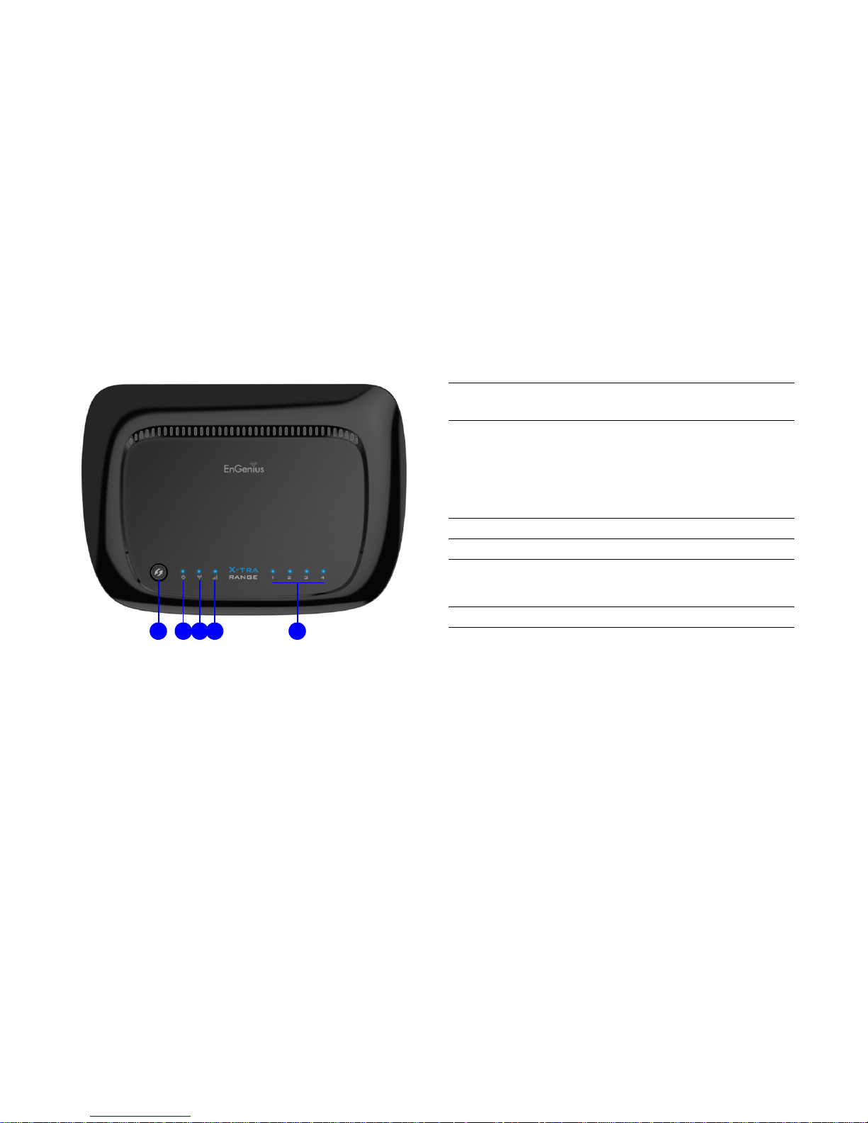
1.1 Product Layout
A
B C D
E
FRONT PANE L
COMPONENTS
DESCRIPTION
A WPS/Reset Button
Wi-Fi Protected Setup button.
To activate WPS, press button for 1~5
seconds.
To reboot the router, press button for 6~10
seconds.
To reset to factory settings, press button for >
11 seconds.
B Power LED Power status LED.
C WLAN LED Wireless LAN (WLAN) status LED.
D
Signal Indicator
LED
Green - Signal is good.
Orange - Signal is normal.
Red - Signal is weak.
E LAN (1 – 4) LEDs LAN port status LED(s).
Page 20
PRODUCT OVERVIEW PRODUCT LAYOUT
1-6
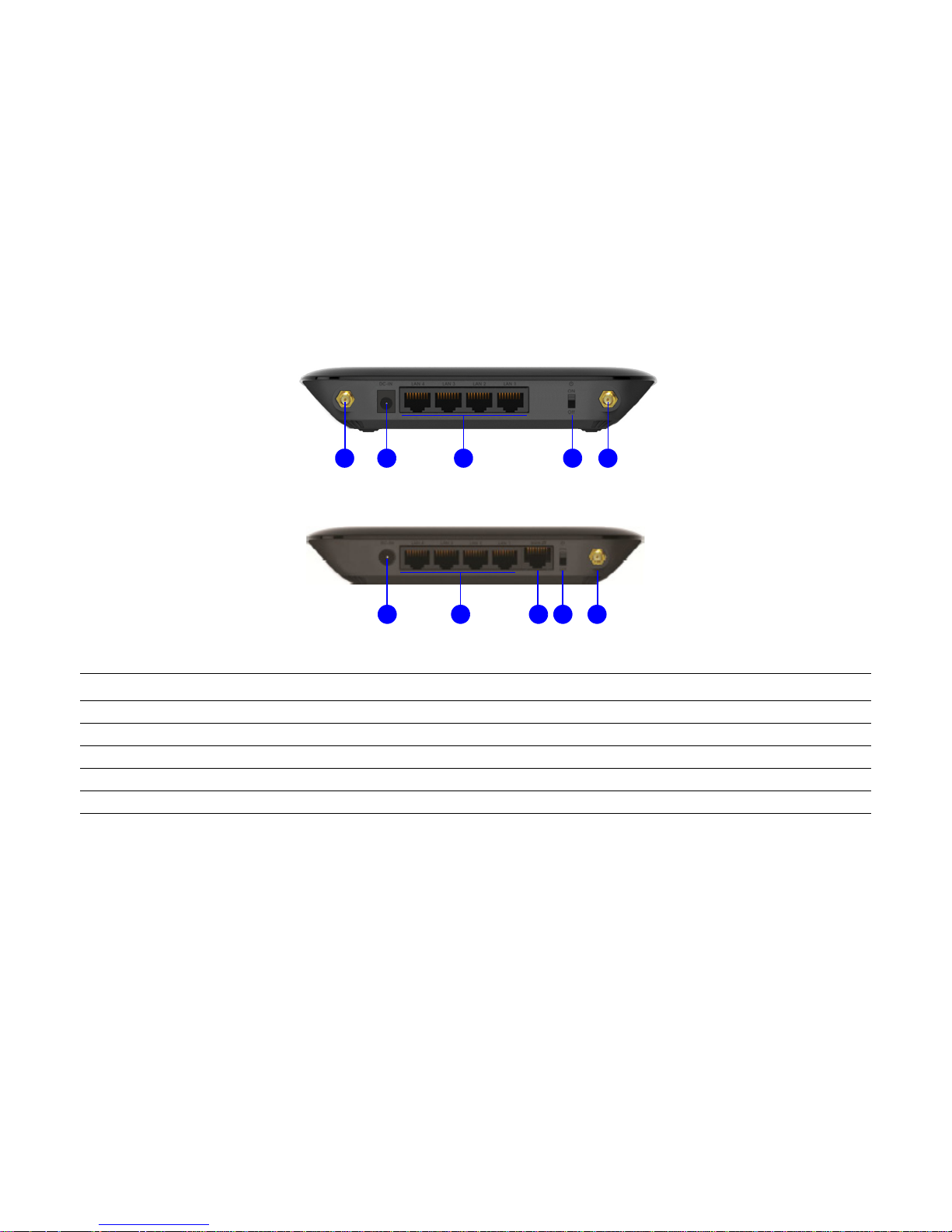
Figure 1-1: ERB300H
Figure 1-2: ERB150H
BACK PANEL COMPONENTS DESCRIPTION
A External Antenna Connectors External interface for the antennas.
B DC Power Jack Connects the router to a DC power adapter source.
C LAN Ports (1 – 4) Connects up to four computers (4) to a local area network (LAN) using Ethernet cable.
D Power Switch Turns the router on or off.
E Passive PoE Port Supplies power to the device through an RJ-45 cable. (ERB150H only)
A
B C D
A
E
B C D
A
Page 21

Installation
Chapter 2
Page 22

INSTALLATION SYSTEM REQUIREMENTS
2-1
2.1 System Requirements
To install the ERB300H/ERB150H, you need the following:
Computer (Windows, Linux, OSX Operating System)
CD-ROM *
Web Browser (Internet Explorer, FireFox, Chrome, Safari)
Network Interface Card with an open RJ-45 Ethernet Port
Wi-Fi Card or USB Wi-Fi Dongle (802.11 B/G/N) **
An existing router or access point (AP) with SSID broad-
cast
CAT5 Ethernet Cables
Note:
* Windows Only: Using ERB300H/ERB150H Setup CD
** Optional
Page 23

INSTALLATION WALL MOUNTING
2-2
2.1 Wall Mounting
Mounting the ERB300H/ERB150H on a wall optimizes the wireless access range.
To mount the device on the wall do the following:
1. Measure the distance from the middle of each mounting
screw hole.
2. Mark the locations of the screw holes on the wall.
3. Drill a hole for each marked location and insert a screw in
each.
4. Install and secure the mounts onto the ERB300H/
ERB150H.
5. Install the ERB300H/ERB150H on the wall.
Note:
Choose a location that is within reach of an electrical
outlet for the AC adapter and the DSL or Cable modem.
Note:
Make sure to leave enough of the screw head above the
wall surface to secure the router.
Page 24

EnGenius Quick Start
Chapter 3
Page 25

ENGENIUS QUICK START INSTALLING THE SOFTWARE
3-1
3.1 Installing the Software
Setup Notes
When considering the placement of the ERB300H/ERB150H
remember the following:
It must be close to an electrical outlet.
Upon first setup, it must be close to the computer that is
used to set up and configure the router.
For optimal wireless access place the router in the center
of the room, at a high altitude and with an unobstructed
view of the other wireless devices.
Other electronic devices can interfere with the wireless
frequency of the router and reduce the wireless access
range.
Note:
Before getting started, please power off the cable or
DSL modem.
Page 26
ENGENIUS QUICK START INSTALLATION
3-2
Installation
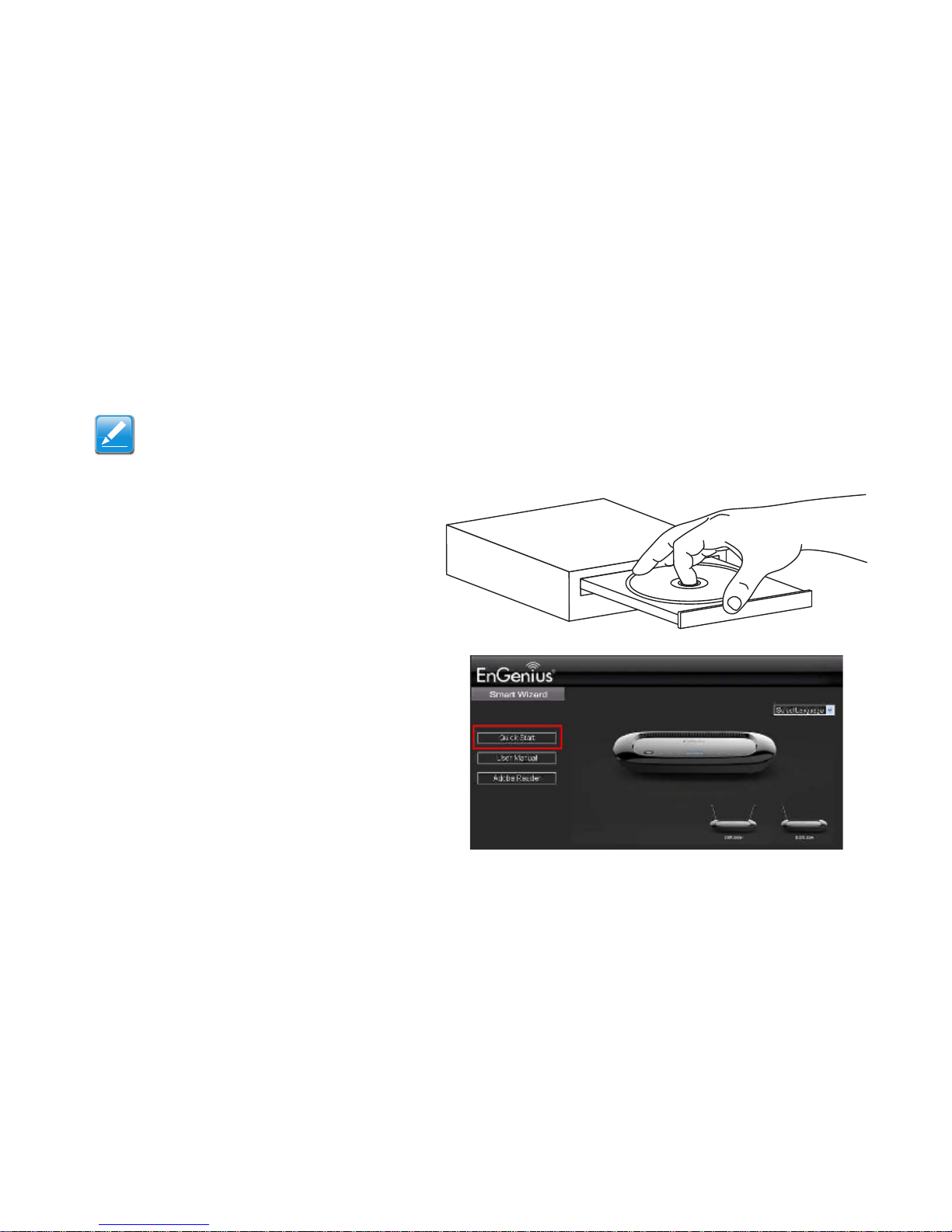
Note:
If the instructions do not automatically start, open a file manager and browse the root folder of the CD-ROM. Look for the file
named index.html and open it.
1. Insert the ERB300H/ERB150H installation CD into the
CD-ROM drive.
2. Click Quick Start. The wizard will guide you through
setting up your ERB300H/ERB150H.
Page 27
ENGENIUS QUICK START CONNECTING THE CABLES
3-3
3.1 Connecting the Cables
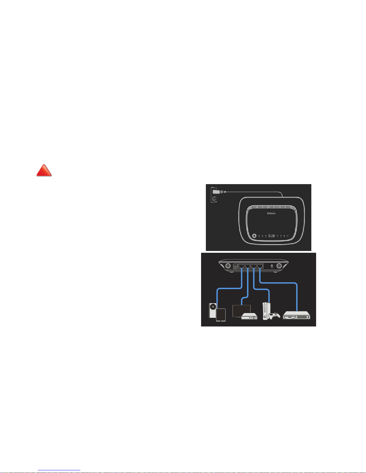
CAUTION!
UNPLUG ALL PERIPHERALS AND THE ADAPTER BEFORE STARTING WITH THIS PROCEDURE.
1. Connect the adapter cable to an electrical outlet.
Note:
The Power LED lights up to show the device is active.
2. If the ERB300H/ERB150H is acting as a client bridge, connect media entertainment devices, a maximum of four, to the
LAN ports. Plug one end of an Ethernet cable into the LAN
port on the back panel of the device. Plug the other end of
the cable into the Ethernet port of the computer.
Note:
Make sure the network cables and power adapter are firmly connected.
!
Page 28

Installation Setup Wizard
Chapter 4
Page 29
INSTALLATION SETUP WIZARD SETTING UP THE ERB300H/ERB150H
4-1
4.1 Setting Up the ERB300H/ERB150H
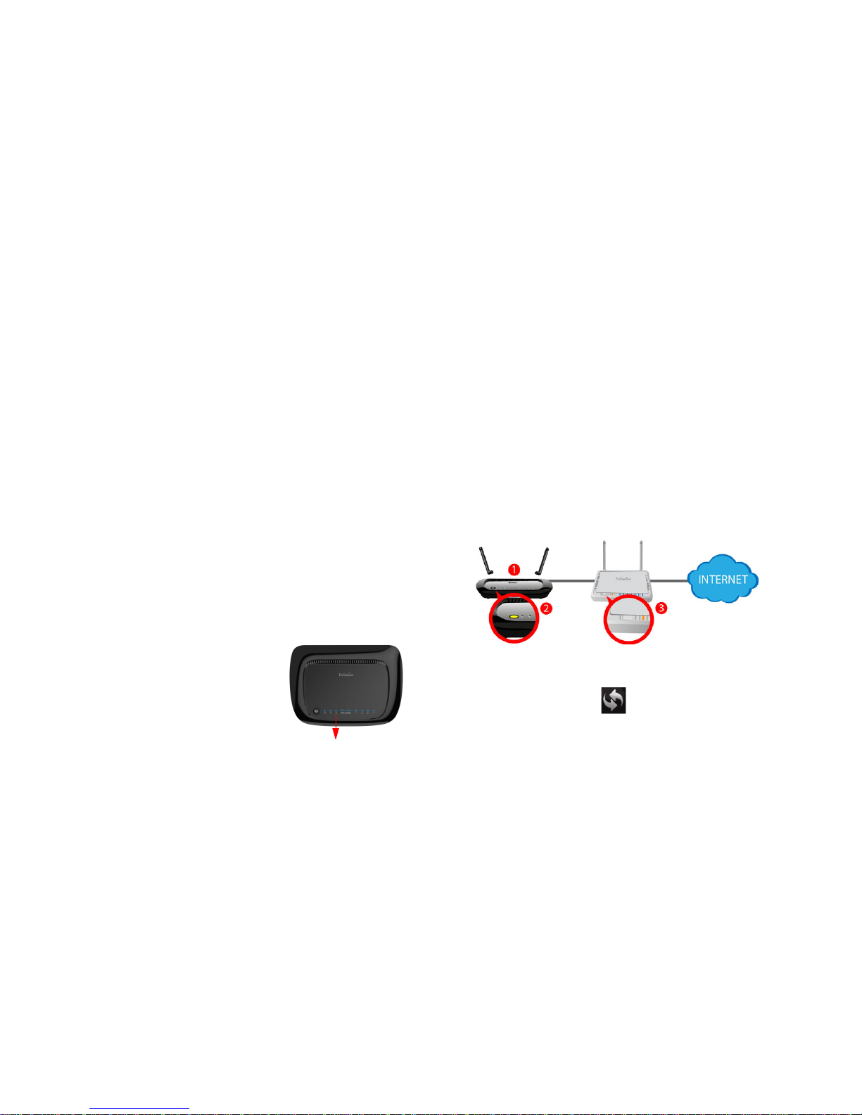
The EnGenius ERB300H/ERB150H is both a Range Extender
and a Media Entertainment Bridge. As a Range Extender, the
ERB300H/ERB150H extends the reach of a wireless network to
areas with poor signal reception. As a Media Entertainment
Bridge, the ERB300H/ERB150H wirelessly connects home
entertainment devices so they may share content.
Using the ERB300H/ERB150H as
a Range Extender
Note:
Place the device in an area that is free of obstructions
and other electronic equipment that may interfere with the
Wi-Fi connection. Use the ERB300H/ERB150H Signal
Indicator to find an optimal location.
Connect the ERB300H/ERB150H to an existing wireless network either by WPS configuration or by Smart Wizard configuration.
Note:
Use the ERB300H/ERB150H Signal Indicator to find an
optimal location.
WPS Configuration
1. Attach the ERB300H/ERB150H‘s Wi-Fi antenna and
power on the device.
2. Press the WPS button on the ERB300H/ERB150H
and hold for until the Power Status LED starts to blink.
3. Within two minutes of activating the WPS button on the
ERB300H/ERB150H, press the WPS button on your
router or access point.
Green- Signal is good.
Orange- Signal is normal.
Red- Signal is weak.
Signal Indicator
Page 30
INSTALLATION SETUP WIZARD USING THE ERB300H/ERB150H AS A RANGE EXTENDER
4-2
The ERB300H/ERB150H Signal Strength LED lights up and the
range extender connects to the wireless network.
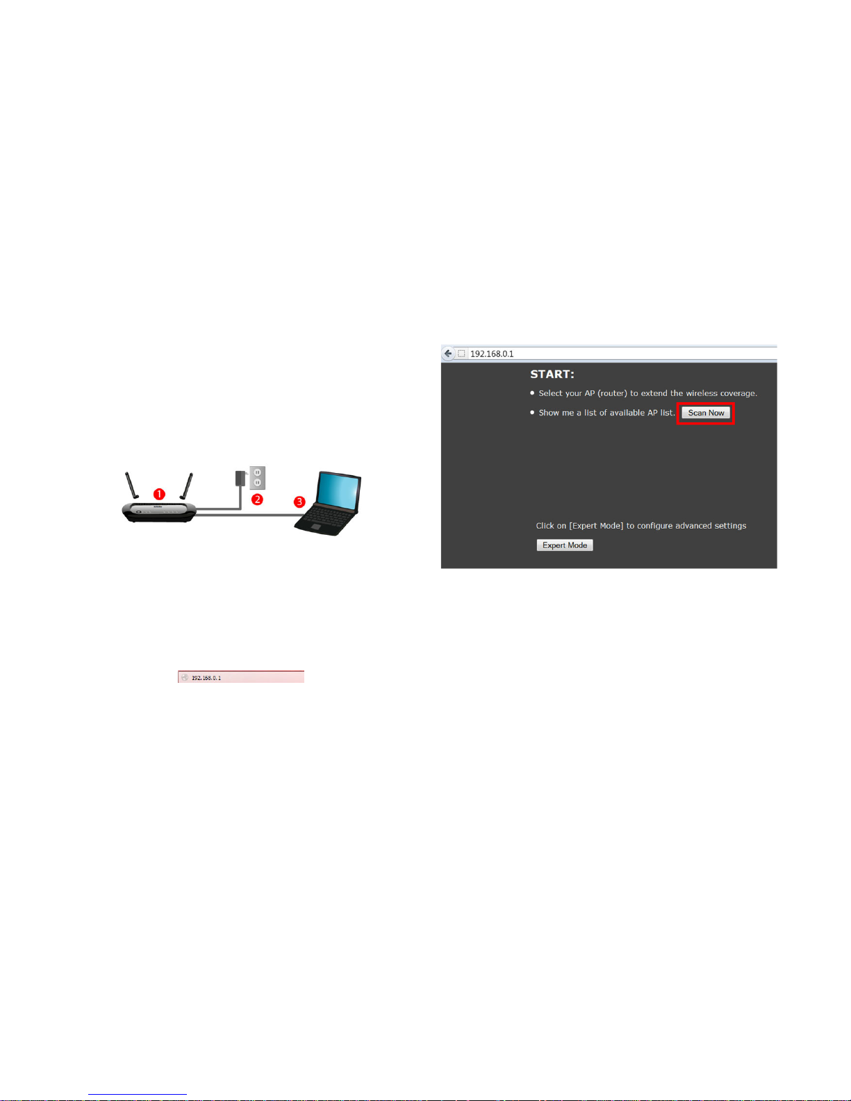
Smart Wizard Configuration
For routers without WPS support, use Smart Wizard to complete the setup.
4. Attach the ERB300H/ERB150H‘s Wi-Fi antenna and
power on the device.
5. Connect a computer to the ERB300H/ERB150H with an
Ethernet cable.
6. Open a web browser and enter the default IP,
192.168.0.1, in the address bar.
7. Click Scan Now to find the target router.
8. Select the target router and click Connect.
Page 31

INSTALLATION SETUP WIZARD USING THE ERB300H/ERB150H AS A RANGE EXTENDER
4-3
Note:
If the target router is not in the list, move the ERB300H/
ERB150H closer to the router and click the Refresh button.
9. Select the target router’s Encryption and Authenti-
cation Type.
10.Enter the Pre-shared Key and click Connect.
Note:
The default SSID, encryption and authentication type of
the ERB300H/ERB150H is initially the same as that of the
target router. The values can be changed by entering a
new value in Repeater (SSID) and selecting a new
value in Encryption and Authentication Type.
To complete the ERB300H/ERB150H installation, remove the
Ethernet cable and place the range extender back in the previously selected location.
The ERB300H/ERB150H immediately starts transmitting and
receiving the wireless signal and is now ready to connect to
your wireless media devices.
Page 32

INSTALLATION SETUP WIZARD USING THE ERB300H/ERB150H AS A MEDIA ENTERTAINMENT BRIDGE
4-4
Note:
When the ERB300H/ERB150H connects via Wi-Fi to a
remote router under bridge or repeater mode, the
device’s IP address changes to the router’s DHCP subnet
address. However, it is not possible to access the device
using the subnet IP address nor can a static IP address
be assigned in the traditional manner.
A work-around is available by following one of these two
procedures:
Enter the model name of the device in a web browser’s
address bar. For example, enter http://erb300h/ to connect to the ERB300H or http://erb150h/ to connect to
the ERB150H.
The default management IP address of the device is
192.168.1.250. To connect to the device over a LAN,
the LAN’s subnet IP address must be 192.168.1.xxx.
Otherwise directly connect a PC to the device.
Manually configure a PC’s IP address to 192.168.1.xxx
and enter 192.168.1.250 in a web browser’s address
bar.
Using the ERB300H/ERB150H as
a Media Entertainment Bridge
Getting Started
Create a wireless media entertainment network using the
ERB300 as a Media Entertainment Bridge (Client Bridge mode)
by following the instructions in the next section.
Setting Up the Media Bridge
Connect the ERB300H/ERB150H to an existing wireless network either by WPS configuration or by Smart Wizard configuration.
Note:
It is recommended to use WPS configuration if the router
supports it.
WPS Configuration
Note:
See WPS Configuration on page 4-1 for details.
Page 33

INSTALLATION SETUP WIZARD USING THE ERB300H/ERB150H AS A MEDIA ENTERTAINMENT BRIDGE
4-5
Smart Wizard Configuration
1. Attach the ERB300H/ERB150H‘s Wi-Fi antenna and
power on the device.
2. Connect your computer to the ERB300H/ERB150H with
an Ethernet cable
3. Open a web browser and enter the default IP,
192.168.0.1, in the address bar.
4. Select Expert Mode to display the Login Page.
5. Enter the default Password: admin and click Login.
Page 34

INSTALLATION SETUP WIZARD USING THE ERB300H/ERB150H AS A MEDIA ENTERTAINMENT BRIDGE
4-6
6. Click System>>Operation Mode to display the Opera-
tion Mode screen.
7. Click Client Bridge in the drop-down menu and click
Apply to save the settings.
Note:
The first time the device is changed to client bridge (CB)
mode, it is assigned an IP address by its DHCP server
(there is no need to set a static IP address).
8. Click Wireless>>Basic to display the Site Survey button. Click the button to view a list of wireless signals.
9. Select your target router and click Add to AP Profile.
10.If the target router uses encryption, enter the password in
Pre-shared Key and click Save.
If the profile was saved successfully, the following screen is displayed.
Click Close to return to the web management page. Select the
target router and click Connect.
Page 35

INSTALLATION SETUP WIZARD USING THE ERB300H/ERB150H AS A MEDIA ENTERTAINMENT BRIDGE
4-7
Note:
The first time the device connects to a router in CB mode
it becomes a DHCP client and automatically configures its
subnet to that of the host network.
To complete the procedure, select media entertainment
devices, a maximum of four, and connect each device to a LAN
port on the ERB300H/ERB150H.
The ERB300H/ERB150H is successfully setup as a client
bridge to the router and is ready to stream media entertainment
applications.
Note:
When the ERB300H/ERB150H connects via Wi-Fi to a
remote router under bridge or repeater mode, the
device’s IP address changes to the router’s DHCP subnet
address. However, it is not possible to access the device
using the subnet IP address nor can a static IP address
be assigned in the traditional manner.
A work-around is available by following one of these two
procedures:
Enter the model name of the device in a web browser’s
address bar. For example, enter http://erb300h/ to connect to the ERB300H or http://erb150h/ to connect to
the ERB150H.
The default management IP address of the device is
192.168.1.250. To connect to the device over a LAN,
the LAN’s subnet IP address must be 192.168.1.xxx.
Otherwise directly connect a PC to the device.
Manually configure a PC’s IP address to 192.168.1.xxx
and enter 192.168.1.250 in a web browser’s address
bar.
Page 36

Web Configuration
Chapter 5
Page 37

WEB CONFIGURATION LOGGING IN
5-1
5.1 Logging In
Note:
If the login screen does not display, enter the default router IP address of 192.168.0.1.
Note:
The default user name is admin and the default password is
admin.
1. At the login screen enter a user name and a password.
2. Click Login to continue.
Page 38

WEB CONFIGURATION WEB MENUS OVERVIEW
5-2
5.1 Web Menus Overview
Universal Repeater Mode Menus
System
View and edit settings that affect system functionality.
Operation Mode Configure the device to be a universal repeater or a client bridge.
Status Display the summary of the current system status.
Schedule schedule services to start and stop at specific times or intervals.
Event Log View recorded system operations and network activity events.
Monitor View the current network traffic bandwidth usage.
Multiple Language Configure the application menu and GUI language.
Page 39

WEB CONFIGURATION UNIVERSAL REPEATER MODE MENUS
5-3
Wireless
Network
View and edit settings for wireless network connectivity.
Status View the current wireless connection status and related information.
Basic Configure the minimum settings required to setup a wireless network connection.
Advanced Configure the advanced network settings.
Security Configure the wireless network security settings.
Filter Configure a list of clients that are allowed to wirelessly connect to the network.
WPS Automate the connection between the a wireless device and the router using an 8-digit PIN.
Client List View the 2.4G wireless devices currently connected to the network.
View and edit settings that affect network connectivity.
Status Display the summary of the Internet status and type of connection.
LAN Configure local area network (LAN) specific and Internet protocol (IP) settings.
Page 40

WEB CONFIGURATION UNIVERSAL REPEATER MODE MENUS
5-4
Management
Tools
View and configure settings for managing the device.
Admin Change the password used to access this device.
SNMP Monitor network-attached devices for conditions that warrant administrative attention.
Firmware Upgrade the firmware of this device.
Configure Save and load system settings from a file on a hard disk drive (HDD).
Reset Reset system settings to factory defaults.
View and configure system and network tools settings.
Time Setting Configure the system time with NTP servers.
Diagnosis Diagnose the current network status.
Page 41

WEB CONFIGURATION UNIVERSAL REPEATER MODE MENUS
5-5
Wizard
Logout
Start the wizard to configure the connection between the device and the router.
Logout of the device application.
Page 42

WEB CONFIGURATION CLIENT BRIDGE MODE MENUS
5-6
Client Bridge Mode Menus
System
Wireless
View and edit settings that affect system functionality.
Operation Mode Configure the device to be a universal repeater or a client bridge.
Status Display the summary of the current system status.
Schedule schedule services to start and stop at specific times or intervals.
Event Log View recorded system operations and network activity events.
Monitor View the current network traffic bandwidth usage.
Multiple Language Configure the application menu and GUI language.
View and edit settings for wireless network connectivity.
Status View the current wireless connection status and related information.
Basic Configure the minimum settings required to setup a wireless network connection.
Advanced Configure the advanced network settings.
WPS Automate the connection between the a wireless device and the router using an 8-digit PIN.
AP Profile Setup wireless security based on profiles.
Page 43

WEB CONFIGURATION CLIENT BRIDGE MODE MENUS
5-7
Network
Management
View and edit settings that affect network connectivity.
Status Display the summary of the Internet status and type of connection.
LAN Configure local area network (LAN) specific and Internet protocol (IP) settings.
View and configure settings for managing the device.
Admin Change the password used to access this device.
SNMP Monitor network-attached devices for conditions that warrant administrative attention.
Firmware Upgrade the firmware of this device.
Configure Save and load system settings from a file on a hard disk drive (HDD).
Reset Reset system settings to factory defaults.
Page 44

WEB CONFIGURATION CLIENT BRIDGE MODE MENUS
5-8
Tools
Logout
View and configure system and network tools settings.
Time Setting Configure the system time with NTP servers.
Diagnosis Diagnose the current network status.
Logout of the device application.
Page 45

WEB CONFIGURATION CLIENT ROUTER MODE MENUS
5-9
Client Router Mode Menus
System
View and edit settings that affect system functionality.
Operation Mode Configure the device to be a universal repeater or a client bridge.
Status Display the summary of the current system status.
DHCP Add DHCP clients and display in a table.
Schedule Schedule services to start and stop at specific times or intervals.
Event Log View recorded system operations and network activity events.
Monitor View the current network traffic bandwidth usage.
Multiple Language Configure the application menu and GUI language.
Page 46

WEB CONFIGURATION CLIENT ROUTER MODE MENUS
5-10
Wireless
Network
View and edit settings for wireless network connectivity.
Status View the current wireless connection status and related information.
Basic Configure the minimum settings required to setup a wireless network connection.
Advanced Configure the advanced network settings.
WPS Automate the connection between the a wireless device and the router using an 8-digit PIN.
AP Profile Setup wireless security based on profiles.
View and edit settings that affect network connectivity.
Status Display the summary of the Internet status and type of connection.
LAN Configure local area network (LAN) specific and Internet protocol (IP) settings.
WAN Configure wide area network (WAN) specific and Internet protocol (IP) settings.
Page 47

WEB CONFIGURATION FIREWALL
5-11
Firewall
View and configure settings for firewall rule sets.
Enable Enable or disable the network firewall.
DMZ Redirect packets from the WAN port IP address to a particular IP address on the LAN.
DoS Enable or disable blocking of denial of service (DoS) attacks.
MAC Filter Configure MAC filters to deny or allow LAN computers from accessing the Internet.
IP Filter Configure IP filters to deny or allow LAN computers from accessing the Internet.
URL Filter Block access to certain Web sites for a particular PC by entering either a full URL address
or just a keyword of the Web site.
Page 48

WEB CONFIGURATION ADVANCED
5-12
Advanced
View and configure advanced system and network settings.
NAT Enable or disable Network Address Translation (NAT).
Port Mapping Re-direct a range of service port numbers to a specified LAN IP address.
Port Forwarding Configure server applications to send and receive data from specific ports on the
network.
Port Triggering Configure applications that require multiple connections and different inbound and
outbound connections.
ALG Configure the application layer gateway (ALG).
UPnP Enable or disable Universal Plug and Play (UPnP) functionality.
QoS Configure the network quality of service (QoS) setting by prioritizing the uplink and downlink
bandwidth.
Static Routing Configure static routing.
Dynamic Routing Configure dynamic routing.
Routing Table Display the routing table.
Page 49

WEB CONFIGURATION ADVANCED
5-13
Management
Tools
View and configure settings for managing the device.
Admin Change the password used to access this device.
SNMP Monitor network-attached devices for conditions that warrant administrative attention.
Firmware Upgrade the firmware of this device.
Configure Save and load system settings from a file on a hard disk drive (HDD).
Reset Reset system settings to factory defaults.
View and configure system and network tools settings.
Time Setting Configure the system time with NTP servers.
DDNS Configure dynamic domain name service (DDNS) settings.
Diagnosis Diagnose the current network status.
Page 50

WEB CONFIGURATION ADVANCED
5-14
Wizard
Logout
Start the wizard to configure the connection between the device and the router.
Logout of the device application.
Page 51

Basic Network Settings
Chapter 6
Page 52

BASIC NETWORK SETTINGS SYSTEM SETUP
6-1
6.0 System Setup
The following sections explain the features and functionality of the ERB300H/ERB150H in universal repeater mode (URM), client
bridge mode (CBM) and client router mode (CRM).
6.0.1 Operation Mode
Set the primary function of the device to act as a universal repeater, client bridge or a client router. The function that is selected
affects which items are available in the main menu.
Note:
If a feature or function does not apply to all modes, a note indicates which modes are applicable. Otherwise, it is assumed the feature
or function applies to all modes.
Operation Mode Select Universal Repeater to extend the router/AP signal
coverage or Client Bridge to function as a bridge for other network devices.
Router Function Select Enable to configure the device as a router or Disable to
function as a client bridge. This feature is only available in client bridge mode.
Figure 6-1: Universal Repeater Mode
(URM)
Page 53

BASIC NETWORK SETTINGS OPERATION MODE
6-2
Figure 6-2: Client Bridge Mode (CBM)
Figure 6-3: Client Router Mode (CRM)
Click Apply to save the settings or Cancel to discard changes.
Page 54

BASIC NETWORK SETTINGS VIEWING SYSTEM STATUS
6-3
6.0.2 Viewing System Status
View the summary of the current system status including system (hardware/software version, date/time), wired network (LAN) and
wireless network (WLAN) information.
System
Operation Mode The router’s operating mode, Universal Repeater, Client
Bridge or Client Router.
System Time The current system date and time.
Hardware Version The hardware version number of the ERB300H/ERB150H.
Serial Number The serial number of the ERB300H/ERB150H. The serial number
is required for customer service or support.
Firmware Version The firmware version number of the ERB300H/ERB150H.
Note:
To update the firmware visit www.engeniusnetworks.com.
Page 55

BASIC NETWORK SETTINGS WAN SETTINGS
6-4
WAN Settings
Note:
This section applies to Client Router mode,
Attain Connection Status Displays the connection status of the device to the
WLAN.
Channel The communications channel used by all stations, or computing devices,
on the network.
ESSID The ID value of a set of one or more interconnected basic service sets
(BSSs).
Security The security setting status (Default: Disabled).
BSSID The unique ID of the BSS using the above channel value on this device.
The ID is the MAC address of the BSSs access point.
Page 56

BASIC NETWORK SETTINGS WLAN STATION INFORMATION
6-5
WLAN Station Information
Note:
This section applies to Client Router mode and Client Bridge mode.
Connection Status Displays the connection status of the device to the WLAN.
Channel The communications channel used by all stations, or computing devices,
on the network.
ESSID The ID value of a set of one or more interconnected basic service sets
(BSSs).
Security The security setting status (Default: Disabled).
BSSID The unique ID of the BSS using the above channel value on this device.
The ID is the MAC address of the BSSs access point.
Page 57

BASIC NETWORK SETTINGS WLAN REPEATER INFORMATION
6-6
WLAN Repeater Information
WLAN Settings
Note:
This section applies to Universal Repeater mode.
Connection Status Displays the connection status of the device to the WLAN.
Channel The communications channel used by all stations, or computing devices,
on the network.
ESSID The ID value of a set of one or more interconnected basic service sets
(BSSs).
Security The security setting status (Default: Disabled).
BSSID The unique ID of the BSS using the above channel value on this device.
The ID is the MAC address of the BSSs access point.
Note:
This section applies to Universal Repeater mode.
Channel The communications channel used by all stations, or computing devices,
on the network.
Page 58

BASIC NETWORK SETTINGS REPEATER SSID
6-7
Repeater SSID
Note:
This section applies to Universal Repeater mode.
ESSID The ID value of a set of one or more interconnected basic service sets
(BSSs).
Security The security setting status (Default: Disabled).
BSSID The unique ID of the BSS using the above channel value on this device.
The ID is the MAC address of the BSSs access point.
Page 59

CHAPTER TITLE CONFIGURING DYNAMIC HOST CONFIGURATION PROTOCOL
6-8
6.0.3 Configuring Dynamic Host Configuration
Protocol
View and configure dynamic host configuration protocol (DHCP) addresses.
DHCP Client Table
Displays the connected DHCP clients whose IP addresses are assigned by the DHCP server on the LAN.
Note:
This section applies to Client Router mode,
WARNING!
Do not modify the settings in this section without a thorough understanding of the parameters.
IP Address Displays the IP address of the static DHCP client device in the table.
MAC Address Displays the MAC address of the static DHCP client device in the
table.
Expiration Time The date and time when the current DHCP address is no longer
valid.
Click Refresh to update the table.
!
Page 60

CHAPTER TITLE ENABLE STATIC DHCP IP
6-9
Enable Static DHCP IP
Current Static DHCP Table
Active static DHCP addresses are listed along with the associated MAC addresses.
Enable Static DHCP IP Click to enable static DHCP IP functionality.
IP Address Enter the IP address of the device to add as a static DHCP client.
MAC Address Enter the MAC address of the device to add as a static DHCP
client.
Click Add to add the device to the static DHCP client table or Reset to return the
table to its previous state.
NO. Displays the ID of the static DHCP client device in the table.
IP Address Displays the IP address of the static DHCP client device in the table.
MAC Address Displays the MAC address of the static DHCP client device in the
table.
Select Click to select static DHCP client devices to be deleted.
Click Delete Selected to remove a selected address. Click Delete All to
remove all addresses from the table. Click Reset to return the table to its previous
state.
Click Apply to save the settings or Cancel to discard changes.
Page 61

BASIC NETWORK SETTINGS CONFIGURING SCHEDULED SERVICES
6-10
6.0.4 Configuring Scheduled Services
Use the Schedule function to start and stop the device services that operate on a routine basis.
Schedule Services Table
The Schedule function relies on the GMT time setting acquired from a network time protocol (NTP) server. See System Time Setting
for details on how to connect the ERB300H/ERB150H to an NTP server.
Enabled Schedule Table Click checkbox to enable schedule services.
Scheduled Services Table Displays a list of scheduled services for
the ERB300H/ERB150H. The properties of each service displayed are:
NO. Displays the ID number of the service in the table.
Description Displays the description of the service.
Service Displays the type of service, either Wireless Active or
Restart.
Schedule Displays the schedule information of when the service is
active or inactive.
Select Select one or more services to edit or delete.
Click Add to add a new service to the table, Edit to edit an existing service, Delete Selected to delete the selected services or Delete
All to delete all services.
Click Apply to save the settings or Cancel to discard changes.
Page 62

BASIC NETWORK SETTINGS ADD/EDIT A SERVICE
6-11
Add/Edit a Service
Create or edit a schedule service type and date/time parameters for a specific service.
Schedule Description Enter the description of the schedule service.
Service Select the type of schedule service, either Wireless
Active or Restart.
Days Select the days of the week to enable the schedule service.
Time of Day Set the start and stop times that the service is active.
Click Apply to save the settings or Cancel to discard changes.
Page 63

BASIC NETWORK SETTINGS CONFIGURING EVENT LOGGING
6-12
6.0.5 Configuring Event Logging
The logging service records and displays important system information and activity on the network. The events are stored in a memory buffer with older data overwritten by newer when the buffer is full.
Log Message List
Shows the current system operations and network activity.
Click Save to save the message list to a text file, Cancel to discard
changes or Refresh to clear the current message list from the memory
buffer.
Page 64

BASIC NETWORK SETTINGS MONITORING BANDWIDTH USAGE
6-13
6.0.6 Monitoring Bandwidth Usage
View bandwidth usage for LAN and WLAN traffic.
Displays the daily bandwidth usage for the LAN and WLAN networks.
Note:
Click Details to view daily, weekly and monthly data.
Page 65

BASIC NETWORK SETTINGS CONFIGURING THE SYSTEM LANGUAGE
6-14
6.0.7 Configuring the System Language
The system supports multiple languages for using the graphical user interface (GUI).
Select the system language to use from the dropdown list.
Page 66

BASIC NETWORK SETTINGS WIRELESS LAN SETUP
6-15
6.1 Wireless LAN Setup
6.1.1 Viewing WLAN Status
View the connection status, extended service set identifier (ESSID), security and basic service set identifiers (BSSID) settings.
WLAN Station Information
Note:
This section applies to Client Router mode and Client Bridge mode.
Connection Status Displays the connection status of the device to the WLAN.
ESSID The ID value of a set of one or more interconnected basic service sets
(BSSs).
Security The security setting status (Default: Disabled).
BSSID The unique ID of the BSS using the channel value on this device. The ID is
the MAC address of the BSSs access point.
Page 67

BASIC NETWORK SETTINGS WLAN REPEATER INFORMATION
6-16
WLAN Repeater Information
WLAN Settings
Note:
This section applies to Universal Repeater mode.
Connection Status Displays the connection status of the device to the WLAN.
ESSID The ID value of a set of one or more interconnected basic service sets
(BSSs).
Security The security setting status (Default: Disabled).
BSSID The unique ID of the BSS using the channel value on this device. The ID is
the MAC address of the BSSs access point.
Note:
This section applies to Universal Repeater mode.
Channel The communications channel used by all stations, or computing devices,
on the network.
Page 68

BASIC NETWORK SETTINGS REPEATER SSID
6-17
Repeater SSID
Note:
This section applies to Universal Repeater mode.
ESSID The ID value of a set of one or more interconnected basic service sets
(BSSs).
Security The security setting status (Default: Disabled).
BSSID The unique ID of the BSS using the above channel value on this device.
The ID is the MAC address of the BSSs access point.
Page 69

BASIC NETWORK SETTINGS BASIC SETTINGS
6-18
6.1.2 Basic Settings
Define the device mode, signal band and connect to multiple ESSIDs.
Note:
This section applies to Client Router mode and Client Bridge mode.
Radio Enable or disable the wireless radio. If the wireless radio is disabled,
wireless access points are not available.
Mode Select the wireless operating mode for the ERB300H/ERB150H.
Band Select the wireless band protocol. The following options are available:
2.4GHz (B)
2.4GHz (N)
2.4GHz (B+G)
2.4GHz (G)
2.4GHz (B+G+N)
Click Site Survey to scan the area for wireless routers that the ERB300H/
ERB150H can connect to. See step 8 of Using the ERB300H/ERB150H as a Media
Entertainment Bridge for detailed instructions on adding an access point profile.
W
Page 70

BASIC NETWORK SETTINGS BASIC SETTINGS
6-19
Note:
This section applies to Universal Repeater mode.
Radio Enable or disable the wireless radio. If the wireless radio is disabled,
wireless access points are not available.
Mode Select the wireless operating mode for the ERB300H/ERB150H.
Band Select the wireless band protocol. The following options are available:
2.4GHz (B)
2.4GHz (N)
2.4GHz (B+G)
2.4GHz (G)
2.4GHz (B+G+N)
Repeater SSID Enter the repeater SSID for the ERB300H/ERB150H.
Channel Select the communications channel used by all stations, or computing
devices, on the network.
Click Site Survey to scan the area for wireless routers that the ERB300H/
ERB150H can connect to. See step 8 of Using the ERB300H/ERB150H as a Media
Entertainment Bridge for detailed instructions on adding an access point profile.
W
Page 71

BASIC NETWORK SETTINGS ADVANCED SETTINGS
6-20
6.1.3 Advanced Settings
Define the advanced settings available on the ERB300H/ERB150H.
WARNING!
Incorrectly changing these settings may cause the device to stop functioning. Do not modify the settings in this section without a
thorough understanding of the parameters.
Note:
This section applies to Client Bridge mode and CLient Router mode.
Fragment Threshold Enter the maximum size of a packet during data
transmission. A value too low could lead to low performance.
RTS Threshold Enter the RTS threshold. If the packet size is smaller than the
RTS threshold, the ERB300H/ERB150H does not use RTS/CTS to send the data
packet.
Tx Power Select the wireless signal strength level. Valid values are between 25%
and 100%.
Click Apply to save the settings or Cancel to discard changes.
Note:
This section applies to Client Bridge mode and CLient Router mode.
!
Page 72

BASIC NETWORK SETTINGS ADVANCED SETTINGS
6-21
Fragment Threshold Enter the maximum size of a packet during data
transmission. A value too low could lead to low performance.
RTS Threshold Enter the RTS threshold. If the packet size is smaller than the
RTS threshold, the ERB300H/ERB150H does not use RTS/CTS to send the data
packet.
Beacon Interval Enter the beacon interval. This is the amount of time that the
ERB300H/ERB150H sets to synchronize the network.
Delivery Traffic Indication Message (DTIM) Period Enter the DTIM period. The
DTIM is a countdown period informing clients of the next point of broadcast and
multicast of messages over the network. Valid values are between 1 and 255.
N Data Rate Select the N data rate. This is the rate in which the ERB300H/
ERB150H will transmit data packets to wireless N compatible devices.
Channel Bandwidth Select the channel bandwidth. The factory default is Auto
20/40MHz. The default setting provides the best performance by auto selecting
channel bandwidth.
Preamble Type Select the preamble type. Long Preamble provides better LAN
compatibility and Short Preamble provides better wireless performance.
CTS Protection Select the type of CTS protection. Using CTS Protection can
lower the data collisions between Wireless B and Wireless G devices and lower
data throughput.
Tx Power Select the wireless signal strength level. Valid values are between 25%
and 100%.
Click Apply to save the settings or Cancel to discard changes.
Page 73

BASIC NETWORK SETTINGS SECURITY
6-22
6.1.4 Security
Enable security options on the wireless network to prevent intrusions to systems on the wireless network.
Note:
This section applies to Universal Repeater mode.
ESSID Selection Select the wireless network group to change the wireless security
settings for.
Broadcast SSID Enable or disable broadcast SSID. Choose whether or not the
wireless group is visible to other members.
Wi-Fi Multimedia (WMM) Enable or disable quality of server (QoS) to optimize the
streaming for bandwidth sensitive data such as HDTV video streaming, online
gaming, VoIP, videoconferencing, and etc.
Encryption Select the encrypt type for the router.
Page 74

BASIC NETWORK SETTINGS ENCRYPTION TYPE
6-23
Encryption Type
Wired Equivalent Privacy (WEP)
Authentication Type Select the type of authentication.
Open System Wireless stations can associate with the ERB300H/ERB150H
without WEP encryption
Shared Key Devices must provide the corresponding WEP key(s) when con-
necting to the ERB300H/ERB150H.
Auto
Key Length Select between 64-bit and 128-encryption.
Key Type Select the type of characters used for the WEP Key: ASCII (5
characters) or Hexadecimal (10 characters).
Default Key
Encryption Key [#] Enter the encryption key(s) used to encrypt the data packets
during data transmission.
Click Apply to save the settings or Cancel to discard changes.
Page 75

BASIC NETWORK SETTINGS ENCRYPTION TYPE
6-24
Wi-Fi Protected Access (WPA) Pre-Shared Key
WPA Type Select the type of WPA.
WPA Temporal Key Integrity Protocol (TKIP) Generates a 128-bit key for
each packet.
WPA2 Advanced Encryption Standard (AES) Government standard
packet encryption which is stronger than TKIP.
WPA2 Mixed Mixed mode allows device to try WPA2 first, and if that fails
selects WPA type.
Pre-Shared Key Type Select the type of pre-shared key as Passphrase
(ASCII) or Hexadecimal.
Pre-Shared Key Enter the pre-shared Key value.
Click Apply to save the settings or Cancel to discard changes.
Page 76

BASIC NETWORK SETTINGS FILTER
6-25
6.1.5 Filter
When Enable Wireless Access Control is selected, only wireless clients with MAC addresses listed in the table are allowed
to connect to the wireless network.
Enable Wireless Access Control
Note:
This section applies to Universal Repeater mode.
WARNING!
Incorrectly changing these settings may cause the device to stop functioning. Do not modify the settings in this section without a
thorough understanding of the parameters.
Description Enter a description of the device allowed to connect to the network.
MAC Address Enter the MAC address of the wireless device.
!
Page 77

BASIC NETWORK SETTINGS MAC ADDRESS FILTERING TABLE
6-26
MAC Address Filtering Table
No. The sequence number of the device.
Description The description of the device.
MAC Address The MAC address of the device.
Select Indicates the device(s) that can have actions performed on them.
Click Delete Selected to remove selected devices from the list, Delete All to
remove all devices form the list or Reset the discard changes.
Click Apply to save the settings or Cancel to discard changes.
Page 78

BASIC NETWORK SETTINGS WI-FI PROTECTED SETUP
6-27
6.1.6 Wi-Fi Protected Setup
Wi-Fi protected setup (WPS) is an easy way to allow wireless clients to connect to the ERB300H/ERB150H. Automate the connection between the device and the ERB300H/ERB150H using a button or a PIN.
WPS Enable or disable WPS.
WPS via Push Button Click Start to Process to activate WPS.
Page 79

BASIC NETWORK SETTINGS AP PROFILE
6-28
6.1.7 AP Profile
AP Profile Table
Note:
This section applies to Client Bridge mode and Client Router mode.
NO. Displays the ID value of the profile.
SSID Displays the SSID value of the profile.
MAC Displays the MAC address of the profile.
Authentication Displays the authentication type of the profile.
Encryption Displays the encryption type of the profile.
Select Select one or more services to edit or delete.
Click Add to add a new AP profile to the table, Edit to edit an existing profile,
Move Up to move a profile up a position in the table, Move Down to move a
profile down a position, Delete Selected to delete the selected profiles,
Delete All to delete all the profiles or Connect to a selected AP.
Page 80

BASIC NETWORK SETTINGS ADD AN AP PROFILE
6-29
Add an AP Profile
Wired Equivalent Privacy (WEP)
SSID Enter the SSID information of the profile.
Encryption Select the encryption type of the profile.
Click Add to add a new AP profile to the table, Edit to edit an existing profile,
Move Up to move a profile up a position in the table, Move Down to move a
profile down a position, Delete Selected to delete the selected profiles,
Delete All to delete all the profiles or Connect to a selected AP.
Authentication Type Select the type of authentication.
Open System Wireless stations can associate with the ERB300H/ERB150H
without WEP encryption
Shared Key Devices must provide the corresponding WEP key(s) when con-
necting to the ERB300H/ERB150H.
Key Length Select between 64-bit and 128-encryption.
Key Type Select the type of characters used for the WEP Key: ASCII (5
characters) or Hexadecimal (10 characters).
Default Key
Encryption Key [#] Enter the encryption key(s) used to encrypt the data packets
during data transmission.
Click Apply to save the settings or Cancel to discard changes.
Page 81

BASIC NETWORK SETTINGS ADD AN AP PROFILE
6-30
Wi-Fi Protected Access (WPA) Pre-Shared Key
Note:
This section applies to Client Bridge mode.
WPA Type Select the type of WPA.
WPA Temporal Key Integrity Protocol (TKIP) Generates a 128-bit key for
each packet.
WPA2 Advanced Encryption Standard (AES) Government standard
packet encryption which is stronger than TKIP.
WPA2 Mixed Mixed mode allows device to try WPA2 first, and if that fails
selects WPA type.
Pre-Shared Key Type Select the type of pre-shared key as Passphrase
(ASCII) or Hexadecimal.
Pre-Shared Key Enter the pre-shared Key value.
Click Apply to save the settings or Cancel to discard changes.
Page 82

BASIC NETWORK SETTINGS ADD AN AP PROFILE
6-31
Wi-Fi Protected Access (WPA) Pre-Shared Key
Note:
This section applies to Client Router mode.
Authentication Type Select the type of authentication.
WPA Temporal Key Integrity Protocol (TKIP) Generates a 128-bit key for
each packet.
WPA2 Advanced Encryption Standard (AES) Government standard
packet encryption which is stronger than TKIP.
Pre-Shared Key Enter the pre-shared Key value.
Click Apply to save the settings or Cancel to discard changes.
Page 83

BASIC NETWORK SETTINGS ADD AN AP PROFILE
6-32
Wi-Fi Protected Access (WPA) RADIUS
Use a RADIUS server to authenticate wireless stations and provide a session key to encrypt data during communications.
Note:
This section applies to Client Bridge mode and Client Router mode.
Authentication Type Select the type of Wireless Protected Access
(WPA).
WEP Generates a 64 or 128-bit key for each packet.
WPA Temporal Key Integrity Protocol (TKIP) Generates a 128-
bit key for each packet.
WPA2 Advanced Encryption Standard (AES) Protects unauthor-
ized access by verifying network users (encryption is stronger than
TKIP).
EAP Method Select the method type used to manage the EAP message
format.
Authentication Identity Enter the authentication identity for the profile.
Authentication Password Enter the authentication password for the
profile.
Click Apply to save the settings or Cancel to discard changes.
Page 84

BASIC NETWORK SETTINGS CLIENT LIST
6-33
6.1.8 Client List
View the wireless devices currently connected to the ERB300H/ERB150H.
WLAN Client Table
Note:
This section applies to Universal Repeater mode.
Interface Displays the type of network connected to the device.
MAC Address Displays the MAC address of device connected to
network.
Rx Displays the number of data packets received by the device.
Tx Displays the number of data packets transmitted by the device.
Signal Displays the signal strength of the device connected to the
network.
Connected Time Displays the amount of time the connected device
has been active on the network.
Idle Time Displays the amount of time the connected device has not
been active on the network.
Click Refresh to refill the list with currently connected devices.
Page 85

BASIC NETWORK SETTINGS NETWORK SETUP
6-34
6.2 Network Setup
6.2.1 Network Status
The Status screen shows a summary of the current network connection information.
LAN Status Settings
Note:
This section applies to Client Bridge mode and Universal Repeater mode.
IP Address Displays the LAN IP address of the ERB300H/ERB150H.
Subnet Mask Displays the LAN subnet mask of the ERB300H/ERB150H.
Default Gateway Displays the default gateway IP address of the ERB300H/
ERB150H.
MAC Address Displays the MAC address of the ERB300H/ERB150H.
Primary DNS Displays the primary DNS address of the ERB300H/ERB150H.
Secondary DNS: Displays the secondary DNS address of the ERB300H/
ERB150H.
Note:
The MAC address is located on the label on the back side of the ERB300H/ERB150H.
Page 86

BASIC NETWORK SETTINGS LAN STATUS SETTINGS
6-35
Note:
This section applies to Client Router mode.
IP Address Displays the LAN IP address of the ERB300H/ERB150H.
Subnet Mask Displays the LAN subnet mask of the ERB300H/ERB150H.
DHCP Server Displays whether the DHCP server functionality is enabled or
disabled.
MAC Address Displays the MAC address of the ERB300H/ERB150H.
Note:
The MAC address is located on the label on the back side of the ERB300H/ERB150H.
Page 87

BASIC NETWORK SETTINGS WAN STATUS SETTINGS
6-36
WAN Status Settings
The WAN Settings, or Internet Status, page shows a summary of the current Internet connection information. This section is also
shown on the System Status page.
Note:
This section applies to Client Router mode.
Attain IP Protocol Display the IP Protocol type used for the ERB300H/ERB150H
(Dynamic IP Address or Static IP Address).
IP Address The router’s WAN IP address.
Subnet Mask The router’s WAN subnet mask.
Default Gateway The ISP’s gateway IP address.
MAC Address The router’s WAN MAC address. The router’s MAC address is
located on the label on the back side of the router.
Primary DNS The primary DNS address of an ISP provider.
Secondary DNS: The secondary DNS address of an ISP provider.
Page 88

BASIC NETWORK SETTINGS LAN SETTINGS
6-37
6.2.2 LAN Settings
Configure the LAN settings for the ERB300H/ERB150H using a static or dynamic IP address.
Bridge Type Configure the bridge type using either a static IP or dynamic IP.
IP Address Enter the LAN IP address of the ERB300H/ERB150H.
Subnet Mask Enter the subnet mask of the ERB300H/ERB150H.
Default Gateway Enter the default gateway of the ERB300H/ERB150H.
DNS Type Select the type of DNS for the ERB300H/ERB150H.
Primary DNS Enter the primary DNS address of the ERB300H/ERB150H.
Secondary DNS Enter the secondary DNS address of the ERB300H/
ERB150H.
802.1d Spanning Tree Enable or disable using the spanning tree protocol
with the ERB300H/ERB150H.
Click Apply to save the settings or Cancel to discard changes.
Page 89

BASIC NETWORK SETTINGS DHCP SERVER
6-38
DHCP Server
The DHCP server assigns IP addresses to the devices on the LAN.
Note:
This section applies to Client Router mode.
DHCP Server Enable or disable the DHCP server (Default: Enabled).
Lease Time Configure the amount of time each allocated IP address can by
used by a client.
Start IP Enter the first IP address in the range of addresses assigned by the
router.
End IP Enter the last IP address in the range of addresses assigned by the
router.
Domain Name: Enter the domain name of the router.
First DNS Address Enter the IP address of the first DNS server.
Second DNS Address Enter the IP address of the second DNS server.
Click Apply to save the settings or Cancel to discard changes.
Page 90

BASIC NETWORK SETTINGS WAN SETTINGS
6-39
6.2.3 WAN Settings
Configure the WAN settings for the ERB300H/ERB150H using a static or dynamic IP address, PPPoE.
Static IP
Setting a static IP address allows an administrator to set a specific IP address for the router and guarantees that it can not be
assigned a different address.
Note:
This section applies to Client Router mode.
IP Address Enter the router’s WAN IP address.
Subnet Mask Enter the router’s WAN subnet mask.
Default Gateway Enter the WAN gateway address.
Primary DNS Enter the primary DNS server address.
Secondary DNS Enter the secondary DNS server address.
Interface Displays the network interface type.
MTU The maximum transmission unit (MTU) specifies the largest packet size
permitted for an internet transmission. The factory default MTU size for static
IP is 1500. The MTU size can be set between 512 and 1500.
Click Apply to save the settings or Cancel to discard changes.
Page 91

BASIC NETWORK SETTINGS DYNAMIC IP
6-40
Dynamic IP
Dynamic IP addressing assigns a different IP address each time a device connects to an ISP service provider. The service is most
commonly used by ISP cable providers.
Host name Assign a name for the internet connection type. This field can be blank.
MAC Address Enter the MAC address of the devices’ network interface card (NIC)
and click Clone MAC. Click Set Default to set the MAC address to the default
value.
Interface Displays the network interface type.
Note:
Some ISP providers require registering the MAC address of the network interface card (NIC) connected directly to the cable or DSL modem. Clone MAC
masks the router's MAC address with the MAC address of the device’s NIC.
Click Apply to save the settings or Cancel to discard changes.
Page 92

BASIC NETWORK SETTINGS POINT-TO-POINT PROTOCOL OVER ETHERNET (PPPOE)
6-41
Point-to-Point Protocol over Ethernet (PPPoE)
Point-to-Point Protocol over Ethernet (PPPoE) is used mainly by ISPs that provide DSL modems to connect to the Internet.
Username Enter the username assigned by an ISP.
Password Enter the password assigned by an ISP.
Service Name Enter the service name of an ISP (optional).
MTU Enter the maximum transmission unit (MTU). The MTU specifies the largest
packet size permitted for an internet transmission (PPPoE default: 1492). The MTU
size can be set between 512 and 1492.
Typ e Configure the connection type between the router and the ISP. Choose
between Keep Connection, Automatic Connection or Manual
Connection.
Idle Timeout Configure the maximum idle time (1 to 1,000 minutes) allowed for an
inactive connection.
Click Apply to save the settings or Cancel to discard changes.
Page 93

BASIC NETWORK SETTINGS POINT-TO-POINT TUNNELLING PROTOCOL (PPTP)
6-42
Point-to-Point Tunnelling Protocol (PPTP)
The point-to-point tunnelling protocol (PPTP) is used in association with virtual private networks (VPNs). There a two parts to a PPTP
connection: the WAN interface settings and the PPTP settings.
WAN Interface Settings
WAN Interface Type Select Dynamic IP Address to assign an IP address
provided by an ISP.
Dynamic IP Address
Host name Assign a name for the internet connection type. This field can be
blank.
MAC Address Enter the MAC address of the devices’ network interface card
(NIC) and click Clone MAC. Click Set Default to set the MAC address to the
default value.
Note:
Some ISP providers require registering the MAC address of the network
interface card (NIC) connected directly to the cable or DSL modem. Clone
MAC masks the router's MAC address with the MAC address of the device’s
NIC.
Page 94

BASIC NETWORK SETTINGS POINT-TO-POINT TUNNELLING PROTOCOL (PPTP)
6-43
Static IP Address
My IP Address Enter the router’s WAN IP address.
My Subnet Mask Enter the router’s WAN subnet IP address.
Gateway IP Address Enter the router’s WAN gateway IP address.
PPTP Settings
Login Enter the username assigned by your ISP.
Password: Enter the password assigned by your ISP.
Service IP Address: Enter the PPTP server IP address provided by your ISP.
Connection ID: Enter the connection ID provided by your ISP (optional).
MTU Enter the maximum transmission unit (MTU). The MTU specifies the largest
packet size (Default: 1462) permitted for an internet transmission. The MTU size
can be set between 512 and 1492.
Typ e Configure the connection type between the router and the ISP. Choose
between Keep Connection, Automatic Connection or Manual
Connection.
Idle Timeout Configure the maximum amount of time, in minutes, allowed for
inactive Internet connection. The Internet connection will be dropped when the
maximum idle time is reached. Valid values are between one and one thousand.
Click Apply to save the settings or Cancel to discard changes.
Page 95

BASIC NETWORK SETTINGS FIREWALL SETUP
6-44
6.3 Firewall Setup
6.3.1 Enabling the Firewall
The ERB300H/ERB150H firewall automatically detects and blocks Denial of Service (DoS) attacks. URL blocking, packet filtering and
stateful packet inspection (SPI) are also supported. The details of the attack and the timestamp are recorded in the security log.
Note:
This section applies to Client Router mode.
Firewall Enable or disable the firewall of the ERB300H/ERB150H.
Click Apply to save the settings or Cancel to discard changes.
Page 96

BASIC NETWORK SETTINGS DEMILITARIZED ZONE SETUP
6-45
6.3.2 Demilitarized Zone Setup
Configuring a device on the LAN as a demilitarized zone (DMZ) host allows unrestricted two-way Internet access for Internet applications, such as online video games, to run from behind the NAT firewall. The DMZ function allows the router to redirect all packets
going to the WAN port IP address to a particular IP address on the LAN. The difference between the virtual server and the DMZ function is that a virtual server redirects a particular service or Internet application, such as FTP, to a particular LAN client or server,
whereas a DMZ redirects all packets, regardless of the service, going to the WAN IP address to a particular LAN client or server.
A DMZ host allows a computer to have all its connections and ports completely open during data transmission.
Note:
This section applies to Client Router mode.
WARNING!
The PC defined as a DMZ host is not protected by the firewall and is vulnerable to malicious network attacks. Do not store or
manage sensitive information on the DMZ host.
Enable DMZ Click Enable DMZ to activate DMZ functionality.
Local IP Address Enter an IP address of a device on the LAN.
Click Apply to save the settings or Cancel to discard changes.
!
Page 97

CHAPTER TITLE DENIAL OF SERVICE ATTACKS SETUP
6-46
6.3.3 Denial of Service Attacks Setup
The Firewall can detect and block DoS attacks. DoS (Denial of Service) attacks can flood your Internet Connection with invalid packets and connection requests, using so much bandwidth and so many resources that Internet access becomes unavailable.
WAN Settings
Note:
This section applies to Client Router mode.
Block DoS Enable or disable blocking DoS attacks.
Click Apply to save the settings or Cancel to discard changes.
Page 98

CHAPTER TITLE MAC FILTER SETUP
6-47
6.3.4 MAC Filter Setup
MAC Filters are used to deny or allow LAN computers from accessing the Internet.
Note:
This section applies to Client Router mode.
Enable MAC Filtering Enable or disable MAC filtering.
Deny/Allow all clients with MAC address listed below to access the network
Description Enter a description for a LAN MAC address.
LAN MAC Address Enter the LAN MAC address.
Click Add to add a device to the MAC Filtering Table or Reset to abort the process.
View and select devices in the MAC Filtering Table.
NO. Displays the ID value of the profile.
Description Displays the description of the profile.
LAN MAC Address Displays the LAN MAC address of the profile.
Select Select one or more services to edit or delete.
Click Delete Selected or Delete All to remove devices from the table. Click
Reset to abort.
Click Apply to save the settings or Cancel to discard changes.
Page 99

CHAPTER TITLE INTERNET PROTOCOL (IP) FILTER SETUP
6-48
6.3.5 Internet Protocol (IP) Filter Setup
IP Filters are used to deny or allow LAN computers from accessing the Internet.
Note:
This section applies to Client Router mode.
Enable IP Filtering Enable or disable IP filtering.
Deny/Allow all clients with IP address listed below to access the network
Allow all clients with IP address listed below to access the network
Description Enter a description for a LAN IP address.
Protocol Select TCP, UDP or Both.
Local IP Address Enter the local IP address range.
Port Range Enter the local port range.
Click Add to add a device to the IP Filtering Table or Reset to abort the process.
Page 100

CHAPTER TITLE INTERNET PROTOCOL (IP) FILTER SETUP
6-49
View and select devices in the IP Filtering Table.
NO. Displays the ID value of the IP filter.
Description Displays the description of the IP filter.
Local IP Address Displays the local IP address of the IP filter.
Protocol Displays the protocol of the IP filter.
Port Range Displays the port range of the IP filter.
Select Select one or more filters to edit or delete.
Click Delete Selected or Delete All to remove filters from the table. Click
Reset to abort.
Click Apply to save the settings or Cancel to discard changes.
 Loading...