

Page 1

EnGenius®Work & Play Series
®
Wireless-N Gigabit Router
User Guide
V1.0
Page 2

TABLE OF CONTENTS
I
TABLE OF CONTENTS
Product Overview
Product Overview 1-1
Package Contents 1-2
Product Layout 1-3
LEDs . . . . . . . . . . . . . . . . . . . . . . . . . . . . . . . . . . . . . . . . . . . . . . . . . . . . . . . . . . . . .1-3
Back Panel Components . . . . . . . . . . . . . . . . . . . . . . . . . . . . . . . . . . . . . . . . . . . . . . . .1-4
Installation
System Requirements 2-1
Wall Mounting 2-2
EnGenius Quick Start
Installing the Software 3-1
Setup Notes . . . . . . . . . . . . . . . . . . . . . . . . . . . . . . . . . . . . . . . . . . . . . . . . . . . . . . . .3-1
Page 3

TABLE OF CONTENTS
II
Installation . . . . . . . . . . . . . . . . . . . . . . . . . . . . . . . . . . . . . . . . . . . . . . . . . . . . . . . . .3-1
Connecting Network Cables 3-3
Web Configuration
Logging In 4-1
Viewing the Dash Board 4-2
Services . . . . . . . . . . . . . . . . . . . . . . . . . . . . . . . . . . . . . . . . . . . . . . . . . . . . . . . . . . .4-3
Home . . . . . . . . . . . . . . . . . . . . . . . . . . . . . . . . . . . . . . . . . . . . . . . . . . . . . . . . . . .4-3
Setup Wizard . . . . . . . . . . . . . . . . . . . . . . . . . . . . . . . . . . . . . . . . . . . . . . . . . . . . . .4-3
Network Settings . . . . . . . . . . . . . . . . . . . . . . . . . . . . . . . . . . . . . . . . . . . . . . . . . . .4-3
Language . . . . . . . . . . . . . . . . . . . . . . . . . . . . . . . . . . . . . . . . . . . . . . . . . . . . . . . .4-3
Logout . . . . . . . . . . . . . . . . . . . . . . . . . . . . . . . . . . . . . . . . . . . . . . . . . . . . . . . . . .4-3
Web Menus Overview 4-4
System . . . . . . . . . . . . . . . . . . . . . . . . . . . . . . . . . . . . . . . . . . . . . . . . . . . . . . . . . . .4-4
Internet . . . . . . . . . . . . . . . . . . . . . . . . . . . . . . . . . . . . . . . . . . . . . . . . . . . . . . . . . . .4-5
Wireless . . . . . . . . . . . . . . . . . . . . . . . . . . . . . . . . . . . . . . . . . . . . . . . . . . . . . . . . . . .4-6
Guest Network . . . . . . . . . . . . . . . . . . . . . . . . . . . . . . . . . . . . . . . . . . . . . . . . . . . . . .4-7
IPv6 . . . . . . . . . . . . . . . . . . . . . . . . . . . . . . . . . . . . . . . . . . . . . . . . . . . . . . . . . . . . .4-8
Firewall . . . . . . . . . . . . . . . . . . . . . . . . . . . . . . . . . . . . . . . . . . . . . . . . . . . . . . . . . . .4-9
Page 4

TABLE OF CONTENTS
III
Advanced . . . . . . . . . . . . . . . . . . . . . . . . . . . . . . . . . . . . . . . . . . . . . . . . . . . . . . . . . 4-10
Tools . . . . . . . . . . . . . . . . . . . . . . . . . . . . . . . . . . . . . . . . . . . . . . . . . . . . . . . . . . . . 4-11
Installation Setup Wizard
Detecting the Internet Connection 5-1
Basic Network Settings
System Setup 6-1
Viewing System Status 6-1
System . . . . . . . . . . . . . . . . . . . . . . . . . . . . . . . . . . . . . . . . . . . . . . . . . . . . . . . . . . .6-1
WAN Settings . . . . . . . . . . . . . . . . . . . . . . . . . . . . . . . . . . . . . . . . . . . . . . . . . . . . . . .6-2
LAN Settings. . . . . . . . . . . . . . . . . . . . . . . . . . . . . . . . . . . . . . . . . . . . . . . . . . . . . . . .6-3
Wireless . . . . . . . . . . . . . . . . . . . . . . . . . . . . . . . . . . . . . . . . . . . . . . . . . . . . . . . . . . .6-3
Guest Network . . . . . . . . . . . . . . . . . . . . . . . . . . . . . . . . . . . . . . . . . . . . . . . . . . . . . .6-4
Configuring Operation Mode 6-5
Router Mode . . . . . . . . . . . . . . . . . . . . . . . . . . . . . . . . . . . . . . . . . . . . . . . . . . . . . . . .6-5
Repeater Mode . . . . . . . . . . . . . . . . . . . . . . . . . . . . . . . . . . . . . . . . . . . . . . . . . . . . . .6-5
Configuring LAN 6-6
LAN IP . . . . . . . . . . . . . . . . . . . . . . . . . . . . . . . . . . . . . . . . . . . . . . . . . . . . . . . . . . . .6-6
Page 5

TABLE OF CONTENTS
IV
DHCP Server. . . . . . . . . . . . . . . . . . . . . . . . . . . . . . . . . . . . . . . . . . . . . . . . . . . . . . . .6-7
DNS Server . . . . . . . . . . . . . . . . . . . . . . . . . . . . . . . . . . . . . . . . . . . . . . . . . . . . . . . .6-8
Configuring DHCP 6-9
DHCP Client Table . . . . . . . . . . . . . . . . . . . . . . . . . . . . . . . . . . . . . . . . . . . . . . . . . . . .6-9
Enable Static DHCP IP . . . . . . . . . . . . . . . . . . . . . . . . . . . . . . . . . . . . . . . . . . . . . . . . .6-9
Current Static DHCP Table . . . . . . . . . . . . . . . . . . . . . . . . . . . . . . . . . . . . . . . . . . . . . 6-10
Configuring Logging 6-11
Log Message List. . . . . . . . . . . . . . . . . . . . . . . . . . . . . . . . . . . . . . . . . . . . . . . . . . . .6-11
Monitoring Bandwidth Usage 6-12
Configuring Languages 6-13
Configuring WAN Settings 6-14
View WAN Status 6-14
WAN Settings . . . . . . . . . . . . . . . . . . . . . . . . . . . . . . . . . . . . . . . . . . . . . . . . . . . . . .6-14
Configuring Dynamic IP 6-15
Dynamic IP. . . . . . . . . . . . . . . . . . . . . . . . . . . . . . . . . . . . . . . . . . . . . . . . . . . . . . . . 6-15
DNS Servers . . . . . . . . . . . . . . . . . . . . . . . . . . . . . . . . . . . . . . . . . . . . . . . . . . . . .6-16
Configuring Static IP 6-17
Static IP. . . . . . . . . . . . . . . . . . . . . . . . . . . . . . . . . . . . . . . . . . . . . . . . . . . . . . . . . .6-17
Configuring PPPoE 6-18
Page 6

TABLE OF CONTENTS
V
Configuring PPTP 6-20
WAN Interface Settings . . . . . . . . . . . . . . . . . . . . . . . . . . . . . . . . . . . . . . . . . . . . . . .6-20
Dynamic IP Address . . . . . . . . . . . . . . . . . . . . . . . . . . . . . . . . . . . . . . . . . . . . . . . .6-20
PPTP Settings . . . . . . . . . . . . . . . . . . . . . . . . . . . . . . . . . . . . . . . . . . . . . . . . . . . . . .6-21
Configuring L2TP 6-22
WAN Interface Settings . . . . . . . . . . . . . . . . . . . . . . . . . . . . . . . . . . . . . . . . . . . . . . .6-22
Dynamic IP Address . . . . . . . . . . . . . . . . . . . . . . . . . . . . . . . . . . . . . . . . . . . . . . . .6-22
L2TP Settings . . . . . . . . . . . . . . . . . . . . . . . . . . . . . . . . . . . . . . . . . . . . . . . . . . . . . .6-23
Configuring DS-Lite 6-24
Wireless LAN Setup 6-25
Configuring Basic Settings 6-25
Access Point Mode . . . . . . . . . . . . . . . . . . . . . . . . . . . . . . . . . . . . . . . . . . . . . . . . . 6-26
Wireless Distribution System Mode . . . . . . . . . . . . . . . . . . . . . . . . . . . . . . . . . . . . . .6-27
Configuring Advanced Settings 6-30
Configuring Security 6-32
Encryption Type . . . . . . . . . . . . . . . . . . . . . . . . . . . . . . . . . . . . . . . . . . . . . . . . . . . .6-33
Wired Equivalent Privacy (WEP) . . . . . . . . . . . . . . . . . . . . . . . . . . . . . . . . . . . . . . . .6-33
Encryption: Wi-Fi Protected Access (WPA) Pre-Shared Key. . . . . . . . . . . . . . . . . . . . . . . 6-34
Encryption: WPA RADIUS . . . . . . . . . . . . . . . . . . . . . . . . . . . . . . . . . . . . . . . . . . . . . . 6-35
Page 7

TABLE OF CONTENTS
VI
Configuring Filter 6-36
Enable Wireless Access Control . . . . . . . . . . . . . . . . . . . . . . . . . . . . . . . . . . . . . . . . . . 6-36
MAC Address Filtering Table . . . . . . . . . . . . . . . . . . . . . . . . . . . . . . . . . . . . . . . . . . . .6-37
Configuring Wi-Fi Protected Setup 6-38
Configuring Client List 6-39
Guest Network 6-40
Enabling Guest Network 6-40
Configuring Guest IP Address 6-41
Viewing Guest Client List 6-42
IPv6 6-43
View IPv6 Status 6-43
Static IPv6 6-44
Configure Autoconfiguration 6-45
Configure PPPoE 6-46
Configuring 6to4 6-48
Configure 6RD 6-49
Configure Link-Local 6-51
Firewall Setup 6-52
Page 8

TABLE OF CONTENTS
VII
Configure Basic Settings 6-52
Configuring Advanced Settings 6-53
Configuring Demilitarized Zone 6-54
Configuring Denial of Service 6-55
WAN Settings . . . . . . . . . . . . . . . . . . . . . . . . . . . . . . . . . . . . . . . . . . . . . . . . . . . . . .6-55
Configure MAC Filter 6-56
Configure IP Filter 6-57
URL Filtering 6-58
Advanced Network Settings 6-59
NAT Setup 6-59
Port Mapping Setup 6-60
Port Forwarding Setup 6-62
Port Triggering Setup 6-64
Application Layer Gateway Setup 6-66
Universal Plug and Play Setup 6-67
Internet Group Multicast Protocol Setup 6-68
Quality of Service Setup 6-69
Priority Queue. . . . . . . . . . . . . . . . . . . . . . . . . . . . . . . . . . . . . . . . . . . . . . . . . . . . . . 6-70
Page 9

TABLE OF CONTENTS
VIII
Bandwidth Allocation . . . . . . . . . . . . . . . . . . . . . . . . . . . . . . . . . . . . . . . . . . . . . . . . . 6-71
Routing Setup 6-72
Wake on LAN Setup 6-74
Tools Setup 6-75
Configuring the Administrator Account 6-75
Configuring the Router’s Time 6-76
Configuring DDNS 6-77
Diagnosing a Network Connection 6-78
Upgrading Firmware 6-79
Backing Up Settings 6-80
Rebooting the Device 6-81
Appendix A
Federal Communication Commission Interference Statement 6-82
Appendix B
Industry Canada Statement 6-84
Page 10

TABLE OF CONTENTS
IX
Appendix C
Link Layers 6-85
Dynamic IP Address (DHCP) . . . . . . . . . . . . . . . . . . . . . . . . . . . . . . . . . . . . . . . . . . . . 6-85
Static IP. . . . . . . . . . . . . . . . . . . . . . . . . . . . . . . . . . . . . . . . . . . . . . . . . . . . . . . . . .6-85
Point-to-Point Protocol over Ethernet (PPPoE). . . . . . . . . . . . . . . . . . . . . . . . . . . . . . . . 6-86
Layer 2 Tunneling Protocol (L2TP) . . . . . . . . . . . . . . . . . . . . . . . . . . . . . . . . . . . . . . . . 6-86
Appendix D
WorldWide Technical Support 6-87
Page 11

COPYRIGHT
X
Copyright
This user guide and its content is copyright of © EnGenius Networks, 2012. All rights reserved.
Any redistribution or reproduction in part or in whole in any form is prohibited.
Do not distribute, transmit, store in any form of electronic retrieval system or commercially exploit the content without the expressed
written permission of EnGenius Networks.
Page 12

CONVENTIONS
XI
Conventions
The following conventions are used to give the user additional information about specific procedures or content. It is important to pay
attention to these conventions as they provide information to prevent damage to equipment or personal injury.
General Conventions
The following general conventions are used in this document.
CAUTION!
CAUTIONS APPEAR BEFORE THE TEXT IT REFERENCES. CAUTIONS APPEAR IN CAPITAL LETTERS TO EMPHASIZE THAT THE MESSAGE CONTAINS VITAL HEALTH
AND SAFETY INFORMATION.
WARNING!
Warning information appears before the text it references to emphasize that the content may prevent damage to the device or equipment.
Important:
Indicates information that is important to know for the proper completion of a procedure, choice of an option, or completing a task.
Note:
Indicates additional information that is relevant to the current process or procedure.
Example:
Indicates information used to demonstrate or explain an associated concept.
!
!
Page 13

CONVENTIONS
XII
N/A:
Indicates that a component or a procedure is not applicable to this model.
Prerequisite:
Indicates a requirement that must be addressed before proceeding with the current function or procedure.
Typographical Conventions
The following typographical conventions are used in this document:
Italics
Indicates book titles, directory names, file names, path names, and program/process names.
Constant width
Indicates computer output shown on a computer screen, including menus, prompts, responses to input, and error messages.
Constant width bold
Indicates commands lines as entered on the computer. Variables contained within user input are shown in angle
brackets (< >).
Bold
Indicates keyboard keys that are pressed by the user.
Page 14

Product Overview
Page 15

PRODUCT OVERVIEW PRODUCT OVERVIEW
1-1
1.1 Product Overview
Thank you for purchasing the ESR9850v2 Wireless-N Gigabit Router from EnGenius Networks.
The EnGenius ESR9850v2 Wireless-N Gigabit Router is a member of the EnGenius Work & Play series of routers.
The ESR9850v2 offers 1 WAN and 4 LAN Gigabit connections and extender signal coverage with two external high sensitive 2dBi
detachable antennas. The ESR9850v2 also feature wireless easy setup – WPS function. It helps user to connect to wireless device
with just one push button.
The ESR9850v2 provides advanced security features to protect your network and the devices connected to it. An SPI Firewall protects the LAN as well as data sent over the Internet. Data encryption protocol, such as WEP, WPA, WPA2 and MAC address Filtering
are some of the other features which block access from unauthorized clients and better manage Wi-Fi accessibility.
The ESR9850v2 supports the next generation IPv6 (Internet Protocol version 6) to enable highly reliable applications and enhanced
security for safer Internet connectivity.
High Performance Gigabit Connection
QoS Wireless Multi-Media (WMM)
Wireless LAN Power Saving
SPI Firewall / DoS Protection
Guest Network
Hardware NAT
IPv6 Compliance
Page 16

PRODUCT OVERVIEW PACKAGE CONTENTS
1-2
1.1 Package Contents
ITEM QUANTITY
Wireless-N Gigabit Router 1
2dBi Antenna 2
Quick Installation Guide 1
12V/1A Power Adapter 1
Ethernet Cable 1
User CD (with user manual) 1
Technical Support Card 1
Page 17

PRODUCT OVERVIEW PRODUCT LAYOUT
1-3
1.1 Product Layout
LEDs
A B C D E
LED DESCRIPTION
A Power/Status Power status LED
B WLAN Wireless LAN (WLAN) status LED
C WAN Internet connection status LED
D LAN (1 – 4) LAN port status LED(s)
E WPS WPS status LED
Page 18

PRODUCT OVERVIEW BACK PANEL COMPONENTS
1-4
Back Panel Components
A A
B
C
D E
F
BACK PANEL
COMPONENTS
DESCRIPTION
A
External Antenna
Connectors
SMA Connectors
B DC Power Jack
Connects the router to a DC power adapter
source
C LAN Ports (1 – 4) 10/100/1000Mbps Ethernet/ RJ-45
D WAN Port 10/100/1000Mbps Ethernet/ RJ-45
E Reset Button
10 seconds for reboot
10~15 seconds for reset to factory default
F
WPS Push
Button
Wi-Fi Protected Setup
Page 19

Installation
Page 20

INSTALLATION SYSTEM REQUIREMENTS
2-1
2.1 System Requirements
To install the ESR9850v2, you need the following:
Computer (Windows, Linux and MAC OS X Operating Systems)
CD-ROM
Web Browser (Internet Explorer, FireFox, Chrome, Safari)
Network Interface Card with an open RJ-45 Ethernet Port
Wi-Fi Card or USB Wi-Fi Dongle (802.11 B/G/N)
xDSL, Cable Modem or Fiber Modem
RJ45 Ethernet Cables
Page 21

INSTALLATION WALL MOUNTING
2-2
2.1 Wall Mounting
Mounting the ESR9850v2 on a wall optimizes the wireless access range.
To mount the device on the wall do the following:
1. Measure the distance from the middle of each mounting screw hole.
2. Mark the locations of the screw holes on the wall.
3. Drill a hole for each marked location and insert a screw in each.
4. Install and secure the mounts onto the ESR9850v2.
5. Install the ESR9850v2 on the wall.
Note:
Choose a location that is within reach of an electrical outlet for the AC adapter and the DSL or Cable modem.
Note:
Make sure to leave enough of the screw head above the wall surface to secure the router.
Page 22

EnGenius Quick Start
Page 23

ENGENIUS QUICK START INSTALLING THE SOFTWARE
3-1
3.1 Installing the Software
Setup Notes
When considering the placement of the ESR9850v2 remember the following:
It must be located close to a DSL or Cable modem.
It must be close to an electrical outlet.
Upon first setup, it must be close to the computer that is used to set up and configure the router.
For optimal wireless access place the router in the center of the room, at a high altitude and with an unobstructed view of the
other wireless devices.
Other electronic devices can interfere with the wireless frequency of the router and reduce the wireless access range.
Installation
Note:
Before getting started, please power off the cable or DSL modem.
Note:
If the instructions do not automatically start, open a file manager and browse the root folder of the CD-ROM. Look for the file named index.html
and open it.
Page 24

ENGENIUS QUICK START INSTALLATION
3-2
1. Insert the ESR9850v2 installation CD into the CD-ROM
drive.
2. Click Quick Start. The wizard will guide you through
setting up your ESR9850v2.
Page 25

ENGENIUS QUICK START CONNECTING NETWORK CABLES
3-3
3.1 Connecting Network Cables
CAUTION!
UNPLUG ALL PERIPHERALS AND THE ROUTER’S ADAPTER BEFORE STARTING WITH THIS PROCEDURE.
1. Connect the adapter cable to an electrical outlet.
Note:
The Power LED lights up to show the device is active.
2. Plug one end of the Ethernet cable into the WAN port on the
back panel of the router. Plug the other end of the cable into
the cable or DSL modem.
!
Power LED
Page 26

ENGENIUS QUICK START CONNECTING NETWORK CABLES
3-4
3. Plug one end of an Ethernet cable into the LAN port on the
back panel of the router. Plug the other end of the cable into
the Ethernet port of the computer.
4. Click Next to display the login screen.
Note:
If the browser does not show the login screen, enter the default router IP address, 192.168.0.1.
Note:
Make sure the network cable and power adapter are firmly connected.
Page 27

Web Configuration
Page 28
WEB CONFIGURATION LOGGING IN
4-1
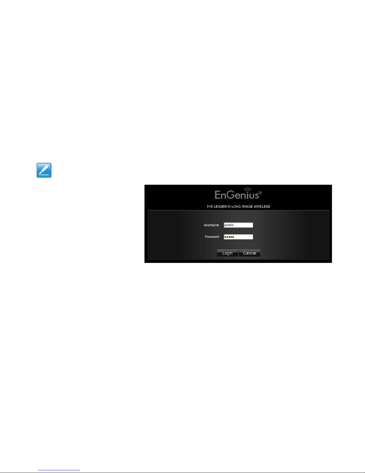
4.1 Logging In
Note:
If the login screen does not display, enter the default router IP address of 192.168.0.1.
Note:
The default user name is admin and the default password is admin.
1. At the login screen enter a user name and a
password.
2. Click Login to continue.
Page 29

WEB CONFIGURATION VIEWING THE DASH BOARD
4-2
4.1 Viewing the Dash Board
The main screen, or dashboard, provides access to all of the router’s services.
Home
Setup Wizard
Network
Settings
Logout
View router information and connection status
Start the setup wizard.
Language
Page 30

WEB CONFIGURATION SERVICES
4-3
Services
The Home, Setup Wizard, Network Settings and Exit links are the main service areas.
Home
The Home link displays the dashboard screen.
Setup Wizard
The Setup Wizard link starts the wizard that automatically configures the router. Refer to “Detecting the Internet Connection” on
page 5-1.
Network Settings
The Network Settings link displays the menus to manually configure the router. Refer to “Web Menus Overview” on page 4-4.
Language
The Language link displays the menu to set the OSD language. Refer to “Configuring Languages” on page 6-13.
Logout
The Logout link closes the router configuration software.
Page 31

WEB CONFIGURATION WEB MENUS OVERVIEW
4-4
4.1 Web Menus Overview
System
View and edit settings that affect system functionality
Status Display the summary of the current system status.
Operation Mode Sets the operator mode as either as an AP router or a Wireless Repeater.
LAN Configure the wired network.
DHCP Configure dynamically allocated IP addresses.
Log View recorded system operations and network activity events.
Monitor View the current network traffic bandwidth usage.
Language Configure the application menu and GUI language.
Page 32

WEB CONFIGURATION INTERNET
4-5
Internet
View and edit settings that affect network connectivity
Status Display the summary of the Internet status and type of connection.
Dynamic IP Setup a dynamic IP connection to an Internet service provider (ISP).
Static IP Setup a static IP connection to an ISP.
PPPoE Setup a PPPoE connection to an ISP.
PPTP Setup a PPTP connection to an ISP.
L2TP Setup an L2TP connection to an ISP.
DS-Lite Setup the IPv6 properties
Page 33

WEB CONFIGURATION WIRELESS
4-6
Wireless
View and edit settings for wireless network connectivity.
Basic Configure the minimum settings required to setup a wireless network connection.
Advanced Configure the advanced wireless network settings.
Security Configure the wireless network security settings.
Filter Configure a list of clients that are allowed to wirelessly connect to the network.
WPS Automate the connection between the a wireless client and the router using an 8-digit PIN.
Client List View the wireless devices currently connected to the network.
Page 34

WEB CONFIGURATION GUEST NETWORK
4-7
Guest Network
View and configure settings for guest network rule sets.
Selection Enable or disable the Guest Network function.
DHCP Server Setting Configure the Guest Network DHCP server settings.
DHCP Client List Configure the Guest Network client list.
Page 35

WEB CONFIGURATION IPV6
4-8
IPv6
View and configure settings for IPv6.
Status Shows IPv6 LAN connection details.
Static IPv6 Set IPv6 address information provided by an Internet Service Provider (ISP).
Auto Configuration IPv6 auto configuration settings.
PPPoE Enter PPPoE IPv6 information provided by an Internet Service Provider (ISP).
6to4 Configure the IPv6 to IPv4 transition mechanism.
6RD Configure the IPv6 rapid deployment mechanism.
Link Local Configure the IPv6 link local address.
Page 36

WEB CONFIGURATION FIREWALL
4-9
Firewall
View and configure settings for firewall rule sets.
Basic Enable or disable the network firewall.
Advanced Configure virtual private network (VPN) packets.
DMZ Redirect packets from the WAN port IP address to a particular IP address on the LAN.
DoS Enable or disable blocking of denial of service (DoS) attacks.
MAC Filter Configure MAC filters to deny or allow LAN computers from accessing the Internet.
IP Filter Configure IP filters to deny or allow LAN computers from accessing the Internet.
URL Filter Block access to certain Web sites for a particular PC by entering either a full URL
address or just a keyword of the Web site.
Page 37

WEB CONFIGURATION ADVANCED
4-10
Advanced
View and configure advanced system and network settings.
NAT Enable or disable Network Address Translation (NAT).
Port Mapping Re-direct a range of service port numbers to a specified LAN IP address.
Port Forwarding Configure server applications to send and receive data from specific ports on
the network.
Port Triggering Configure applications that require multiple connections and different inbound
and outbound connections.
ALG Configure the application layer gateway (ALG).
UPnP Enable or disable Universal Plug and Play (UPnP) functionality.
IGMP Enable or disable the Internet Group Multicast Protocol (IGMP).
QoS Configure the network quality of service (QoS) setting by prioritizing the uplink and downlink
bandwidth.
Routing Configure static routing.
WOL Configure wake on LAN (WOL) to turn on a computer over the network.
Page 38

WEB CONFIGURATION TOOLS
4-11
Tools
View and configure system and network tools settings.
Admin Configure the administrator password used to login to the router.
Time Configure the system time on the router.
DDNS Map a static domain name to a dynamic IP address.
Diagnosis Check if a specific computer is connected to the LAN.
Firmware Update the router’s firmware.
Backup Load or save configuration settings from a backup file or restore the factory default set-
tings.
Reset Manually reset the router.
Page 39

Installation Setup Wizard
Page 40

INSTALLATION SETUP WIZARD DETECTING THE INTERNET CONNECTION
5-1
5.1 Detecting the Internet Connection
Use the Wizard to automatically detect the type of Internet connection.
1. Insert the ESR9850v2 Installation CD into your CD-ROM drive to display the EnGenius Smart Wizard screen.
2. Click Quick Start to continue an display the Wizard Introduction screen.
Page 41

INSTALLATION SETUP WIZARD DETECTING THE INTERNET CONNECTION
5-2
3. Click Next to continue or Skip to cancel the wizard.
Page 42

INSTALLATION SETUP WIZARD DETECTING THE INTERNET CONNECTION
5-3
4. To choose an operation mode, perform one of the follow steps:
Click AP Router Mode and refer to Detecting the Internet Connection in AP Router Mode for the remaining steps.
Click AP Repeater Mode and refer to Detecting the Internet Connection in AP Repeater Mode for the remaining steps.
Page 43

INSTALLATION SETUP WIZARD DETECTING THE INTERNET CONNECTION
5-4
Detecting the Internet Connection in AP Router Mode
1. The Wizard displays a progress bar while detecting the type of Internet connection.
Progress Bar
Page 44

INSTALLATION SETUP WIZARD DETECTING THE INTERNET CONNECTION
5-5
2. If the ESR9850v2 can not detect the type of Internet connection, the following screen is displayed.
3. Select a login method from the dropdown list.
4. Fill in the required information.
Note:
This process may take several seconds.
Page 45

INSTALLATION SETUP WIZARD DETECTING THE INTERNET CONNECTION
5-6
5. Click Next to save these settings and continue to the next step; click Rescan to detect the Internet connection method; click
Skip to discard changes and continue to the next step.
6. For the Wireless connection, in the SSID text field enter a router name and in the Key text field enter a password.
Note:
There are four methods available to connect to the Internet: DHCP, Static IP, PPPoE and LT2P. For a description of each method, refer to “Link
Layers” on page 6-85. For configuration instructions, refer to “Configuring Dynamic IP” on page 6-15, “Configuring Static IP” on page 6-17,
“Configuring PPPoE” on page 6-18 and “Configuring L2TP” on page 6-22.
WARNING!
Select High as the security level to best secure the wireless network.
!
Page 46

INSTALLATION SETUP WIZARD DETECTING THE INTERNET CONNECTION
5-7
7. Click Next to save these settings and continue to the next step or click Skip to discard changes and continue to the next step.
8. Review the settings.
9. Click Apply to save the information entered in the previous steps.
The ESR9850v2 setup is complete.
Page 47

INSTALLATION SETUP WIZARD DETECTING THE INTERNET CONNECTION
5-8
Detecting the Internet Connection in AP Repeater Mode
1. In the SSID text field enter a router name and in the Key text field enter a password.
2. Click Next to save these settings and continue to the next step or click Skip to discard changes and continue to the next step.
Page 48

INSTALLATION SETUP WIZARD DETECTING THE INTERNET CONNECTION
5-9
3. Review the settings.
4. Click Apply to save the information entered in the previous steps.
The ESR9850v2 setup is complete.
Page 49

Basic Network Settings
Page 50

BASIC NETWORK SETTINGS SYSTEM SETUP
6-1
6.2 System Setup
6.2.1 Viewing System Status
The status page shows the summary of the current system status including system (hardware/software version, date/time), Internet
connection (WAN), wired network (LAN) and wireless network (WLAN) information.
System
Note:
To update the firmware visit www.engeniusnetworks.com.
Model The model name of the ESR9850v2.
Mode The router’s operating mode (AP Router or WDS).
Uptime The amount of time the device has been active.
Current Date/Time The current system date and time.
Hardware Version The hardware version number of the
ESR9850v2.
Serial Number The serial number of the ESR9850v2.
The serial number is required for customer service or support.
Application Version The firmware version number of the
ESR9850v2.
Page 51

BASIC NETWORK SETTINGS WAN SETTINGS
6-2
WAN Settings
Attain IP Protocol Displays the IP protocol in use for the
ESR9850v2. It can be a dynamic or static IP address.
IP Address The router’s IP address as designated by an
ISP provider.
Subnet Mask The router’s WAN subnet mask as desig-
nated by an ISP provider.
Default Gateway The router’s gateway address as desig-
nated by an ISP provider.
MAC Address The router’s WAN MAC address. The
router’s MAC address is located on the label on the back
side of the router.
Primary DNS The primary DNS of an ISP provider.
Secondary DNS The secondary DNS of an ISP provider.
Page 52

BASIC NETWORK SETTINGS LAN SETTINGS
6-3
LAN Settings
Wireless
IP Address The router’s local IP address. The default
LAN IP address is 192.168.0.1.
Subnet Mask The router’s local subnet mask.
DHCP Server: The DHCP setting status (Default:
Enabled).
MAC Address The router’s LAN MAC address.
Channel The communications channel used by all sta-
tions, or computing devices, on the network.
ESSID The ID value of a set of one or more intercon-
nected basic service sets (BSSs).
Security The security setting status (Default: Dis-
abled).
BSSID The unique ID of the BSS using the above
channel value on this router. The ID is the MAC address
of the BSSs access point.
Associated Clients The number of clients associated
with this SSID.
Page 53

BASIC NETWORK SETTINGS GUEST NETWORK
6-4
Guest Network
Guest Network The guest network status. (Default: Disabled)
Page 54

BASIC NETWORK SETTINGS CONFIGURING OPERATION MODE
6-5
6.2.1 Configuring Operation Mode
The ESR9850v2 supports two different operation modes: Router Mode and Repeater Mode.
Router Mode
In router mode the internal DHCP server allows a number of LANs to automatically generate IP addresses to share the same Internet
connection. In this mode, connect an AP/WISP wirelessly and connect to LANs via a wired connection.
Repeater Mode
Repeater mode is used to regenerate or replicate signals that are weakened or distorted by transmission over long distances and
through areas with high levels of electromagnetic interference (EMI).
Note:
The device DHCP server is disabled when the device is set to repeater mode.
Operation Mode Select AP Router Mode or Repeater
Mode.
Note:
The device must restart after changing modes.
Page 55

BASIC NETWORK SETTINGS CONFIGURING LAN
6-6
6.2.1 Configuring LAN
Configure the wired network settings in the LAN section. The router’s IP is defined in the IP Address field. The default setting of the
DHCP server is set to enabled so that network clients can be automatically assigned a virtual IP addresses. Advanced users may
configure DNS server settings to meet specific requirements. Changing the settings in this section are not necessary for most situations.
LAN IP
Note:
Keep the default values if you are uncertain of the settings values.
IP Address Configure the router’s LAN IP address.
IP Subnet Mask Configure the router’s LAN Subnet
Mask
802.1d Spanning Tree The 802.1d Spanning Tree set-
tings is disabled by default. When enabled, the spanning
tree protocol is applied to prevent network loops (transmissions won’t pass the same node twice to reach the
destination).
\
Note:
The default device IP address is 192.168.0.1.
Page 56

BASIC NETWORK SETTINGS DHCP SERVER
6-7
DHCP Server
The DHCP server assigns IP addresses to the devices on the LAN.
DHCP Server Enable or disable the DHCP server (Default: Enabled).
Lease Time Configure the amount of time each allocated IP address can by
used by a client.
Start IP The first IP address in the range of addresses assigned by the
router.
End IP The last IP address in the range of addresses assigned by the router.
Domain Name: The domain name of the router.
Page 57

BASIC NETWORK SETTINGS DNS SERVER
6-8
DNS Server
The domain name system (DNS) server translates a domain or website name into a uniform resource locator (URL), or Internet
address. There are four options to choose from: From ISP, User-Defined, DNS Relay or None. Select From ISP to retrieve the DNS
address value from the ISP; select User-Defined to assign a custom DNS server address; select DNS Relay to forward all queries
to a relay, which in turn sends them to an ISP’s DNS server; select None to assign no server.
First DNS Server Configure the first, or primary, DNS server.
(Default = None)
Second DNS Server Configure the second, or secondary, DNS
server. (Default = None)
Click Apply to save the settings.
Page 58

BASIC NETWORK SETTINGS CONFIGURING DHCP
6-9
6.2.1 Configuring DHCP
View active dynamically allocated IP (DHCP) addresses and configure and view static DHCP IP addresses.
DHCP Client Table
Enable Static DHCP IP
WARNING!
Do not modify the settings in this section without a thorough understanding of the parameters.
Displays the connected DHCP clients whose IP
addresses are assigned by the DHCP server on
the LAN.
Click Refresh to update the table.
Click Enable Static DHCP IP to add more
static DHCP IP addresses.
Click Reset to return the table to its previous
state.
!
Page 59

BASIC NETWORK SETTINGS CURRENT STATIC DHCP TABLE
6-10
Current Static DHCP Table
Active static DHCP addresses are listed along with the
associated MAC addresses.
Click Delete Selected to remove a selected address.
Click Delete All to remove all addresses from the
table. Click Reset to return the table to its previous state.
Click Apply to save the settings.
Page 60

BASIC NETWORK SETTINGS CONFIGURING LOGGING
6-11
6.2.1 Configuring Logging
The logging service records and displays important system information and activity on the network. The events are stored in a memory buffer with older data overwritten by newer when the buffer is full.
Log Message List
Shows the current system operations and network activity.
Click Save to store data to a log file.
Click Clear to empty the log file.
Click Refresh to empty the log file and begin updating it with new
data.
Page 61

BASIC NETWORK SETTINGS MONITORING BANDWIDTH USAGE
6-12
6.2.1 Monitoring Bandwidth Usage
View bandwidth usage for LAN and WLAN traffic.
Displays the bandwidth usage for the WLAN and LAN networks.
Page 62

BASIC NETWORK SETTINGS CONFIGURING LANGUAGES
6-13
6.2.1 Configuring Languages
The router supports multiple languages for using the graphical user interface (GUI).
Select the language to use from the dropdown list.
Page 63

BASIC NETWORK SETTINGS CONFIGURING WAN SETTINGS
6-14
6.3 Configuring WAN Settings
6.3.1 View WAN Status
The WAN Settings, or Internet Status, page shows a summary of the current Internet connection information. This section is also
shown on the System Status page.
WAN Settings
Attain IP Protocol Display the IP Protocol type
used for the ESR9850v2 (Dynamic IP Address
or Static IP Address).
IP Address The router’s WAN IP address.
Subnet Mask The router’s WAN subnet mask.
Default Gateway The ISP’s gateway IP address.
MAC Address The router’s WAN MAC address.
The router’s MAC address is located on the label
on the back side of the router.
Primary DNS The primary DNS address of an
ISP provider.
Secondary DNS: The secondary DNS address of
an ISP provider.
Page 64

BASIC NETWORK SETTINGS CONFIGURING DYNAMIC IP
6-15
6.3.1 Configuring Dynamic IP
Dynamic IP addressing assigns a different IP address each time a device connects to an ISP service provider. The service is most
commonly used by ISP cable providers.
Dynamic IP
Host name Assign a name for the internet connection type.
This field can be blank.
MTU Configure the maximum transmission unit (MTU). The
MTU specifies the largest packet size permitted for an internet transmission. The factory default MTU size for Dynamic
IP (DHCP) is 1500. The MTU size can be set between 512
and 1500.
Clone MAC Enter the MAC address of the devices’ network
interface card (NIC) in the MAC address field and click Clone
MAC.
Note:
Some ISP providers require registering the MAC address of
the network interface card (NIC) connected directly to the
cable or DSL modem. Clone MAC masks the router's MAC
address with the MAC address of the device’s NIC.
Page 65

BASIC NETWORK SETTINGS DYNAMIC IP
6-16
DNS Servers
The DNS server translates a domain or website name into a uniform resource locator (URL), or Internet address. There are two
options to choose from: From ISP or User-Defined. Select From ISP to retrieve the DNS address value from the ISP; select User-
Defined to assign a custom DNS server address.
DNS Server Configure the type of DNS server. (Default =
From ISP)
First DNS Server Configure the first, or primary, DNS server.
Second DNS Server: Configure the second, or secondary,
DNS server.
Click Apply to save the settings or Cancel to discard the
changes.
Page 66

BASIC NETWORK SETTINGS CONFIGURING STATIC IP
6-17
6.3.1 Configuring Static IP
Setting a static IP address allows an administrator to set a specific IP address for the router and guarantees that it can not be
assigned a different address.
Static IP
IP Address The router’s WAN IP address.
Subnet Mask The router’s WAN subnet mask.
Default Gateway The WAN gateway address.
Primary DNS The primary DNS server address.
Secondary DNS The secondary DNS server address.
MTU The maximum transmission unit (MTU) specifies
the largest packet size permitted for an internet transmission. The factory default MTU size for static IP is
1500. The MTU size can be set between 512 and
1500.
MAC Address The router’s MAC address.
Click Apply to save the settings or Cancel to discard the
changes.
Page 67

BASIC NETWORK SETTINGS CONFIGURING PPPOE
6-18
6.3.1 Configuring PPPoE
Point-to-Point Protocol over Ethernet (PPPoE) is used mainly by ISPs that provide DSL modems to connect to the Internet.
Username Enter the username assigned by an ISP.
Password Enter the password assigned by an ISP.
Service Name Enter the service name of an ISP
(optional).
MTU Enter the maximum transmission unit (MTU). The
MTU specifies the largest packet size permitted for an
internet transmission (PPPoE default: 1492). The MTU
size can be set between 512 and 1492.
Authentication Type Select the type of authentication
provided by the ISP: Auto, PAP, or CHAP. If unsure of the
best setting, select Auto or check with your Internet Service Provider.
Page 68

BASIC NETWORK SETTINGS CONFIGURING PPPOE
6-19
Type Configure the connection type between the router
and the ISP. Choose between Keep Connection,
Automatic Connection or Manual Connection.
Idle Timeout Configure the maximum idle time (1 to
1,000 minutes) allowed for an inactive connection.
Clone MAC Enter the MAC address of the devices’ net-
work interface card (NIC) in the MAC address field and
click Clone MAC.
Some ISP providers require registering the MAC address
of the network interface card (NIC) connected directly to
the cable or DSL modem. Clone MAC masks the router's
MAC address with the MAC address of the device’s NIC.
Click Apply to save the settings or Cancel to discard the
changes.
Page 69

BASIC NETWORK SETTINGS CONFIGURING PPTP
6-20
6.3.1 Configuring PPTP
The point-to-point tunnelling protocol (PPTP) is used in association with virtual private networks (VPNs). There a two parts to a PPTP
connection: the WAN interface settings and the PPTP settings.
WAN Interface Settings
Dynamic IP Address
WAN Interface Type Select Dynamic IP Address to
assign an IP address provided by an ISP.
Hostname Enter a host name of an ISP. (optional).
Clone MAC Enter the MAC address of the devices’ net-
work interface card (NIC) in the MAC address field and
click Clone MAC.
Note:
Some ISP providers require registering the MAC address
of the network interface card (NIC) connected directly to
the cable or DSL modem. Clone MAC masks the router's
MAC address with the MAC address of the device’s NIC.
Page 70

BASIC NETWORK SETTINGS PPTP SETTINGS
6-21
PPTP Settings
User Name Enter the username assigned by your ISP.
Password: Enter the password assigned by your ISP.
Service IP Address: Enter the PPTP server IP address
provided by your ISP.
Connection ID: Enter the connection ID provided by your
ISP (optional).
MTU Enter the maximum transmission unit (MTU). The
MTU specifies the largest packet size (Default: 1462) permitted for an internet transmission. The MTU size can be
set between 512 and 1492.
Type Configure the connection type between the router
and the ISP. Choose between Keep Connection, Automatic Connection or Manual Connection.
Idle Timeout Configure the maximum amount of time, in
minutes, allowed for inactive Internet connection. The
Internet connection will be dropped when the maximum
idle time is reached. Valid values are between one and
one thousand.
Click Apply to save the settings or Cancel to discard the
changes.
Page 71

BASIC NETWORK SETTINGS CONFIGURING L2TP
6-22
6.3.1 Configuring L2TP
The layer 2 tunneling protocol (L2TP) is used in association with virtual private networks (VPNs). There a two parts to a L2TP connection: the WAN interface settings and the L2TP settings.
WAN Interface Settings
Dynamic IP Address
WAN Interface Type Select Dynamic IP Address to
assign an IP address provided by an ISP.
Hostname Enter a host name of an ISP (optional).
Clone MAC Enter the MAC address of the devices’ net-
work interface card (NIC) in the MAC address field and
click Clone MAC.
Some ISP providers require registering the MAC address
of the network interface card (NIC) connected directly to
the cable or DSL modem. Clone MAC masks the router's
MAC address with the MAC address of the device’s NIC.
Page 72

BASIC NETWORK SETTINGS L2TP SETTINGS
6-23
L2TP Settings
User Name Enter the username assigned by an ISP.
Password: Enter the password assigned by an ISP.
Service IP Address: Enter the L2TP server IP address
provided by an ISP.
Connection ID: Enter the connection ID provided by an
ISP (optional).
MTU Enter the maximum transmission unit (MTU). The
MTU specifies the largest packet size (Default: 1460) permitted for an internet transmission. The MTU size can be
set between 512 and 1492.
Type Configure the connection type between the router
and the ISP. Choose between Keep Connection, Automatic Connection or Manual Connection.
Idle Timeout Configure the maximum amount of time, in
minutes, allowed for inactive Internet connection. The
Internet connection will be dropped when the maximum
idle time is reached. Valid values are between one and
one thousand.
Click Apply to save the settings or Cancel to discard the
changes.
Page 73

CHAPTER TITLE CONFIGURING DS-LITE
6-24
6.3.1 Configuring DS-Lite
Dual-Stack Lite, or DS-Lite, allows ISPs to stop IPv4 addresses from reaching a customer’s network devices and only use IPv6.
DS-Lite Configuration Select DS-Lite DHCPv6
Option or Manual Configuration
AFTR IPv6 Address Enter the AFTR IPv6 connection
type
B4 IPv4 Address Enter an Optional B4 IPv4 address.
WAN IPv6 Address Enter the WAN IPv6 address.
IPv6 WAN Default Gateway Enter the IPv6 WAN default
gateway address.
Page 74

BASIC NETWORK SETTINGS WIRELESS LAN SETUP
6-25
6.4 Wireless LAN Setup
6.4.1 Configuring Basic Settings
Radio Enable or disable the wireless radio. If the wireless
radio is disabled, wireless access points are not available.
Mode Select the wireless operating mode for the router.
Two modes are available: Access Point or Wireless Distribution System (WDS) mode.
AP Provides a connection access point for wireless
devices.
WDS Allows the wireless network to be expanded
using multiple access points without wired connections.
Page 75

BASIC NETWORK SETTINGS CONFIGURING BASIC SETTINGS
6-26
Access Point Mode
Configure the wireless settings of the router in access point mode.
Band: Select a wireless standard for the network from the
following options:
2.4 GHz (B)
2.4 GHz (N)
2.4 GHz (B+G)
2.4 GHz (G)
2.4 GHz (B+G+N)
Enable SSID# Select the number of wireless groups,
between one and four, available on the network.
SSID[#] Enter the name of the wireless network(s).
Auto Channel Enable or disable having the router auto-
matically select a channel for the wireless network. Auto
channel is enabled by default. Select disable to manually
assign a specific channel. (Default = Disable)
Check Channel Time When auto channel is enabled,
select time period that the system checks the appropriate
channel for the router.
Channel When auto channel is disabled, select a channel
to assign to the wireless network. Valid value are from one
to eleven in the US and one to thirteen in the EU.
Page 76

BASIC NETWORK SETTINGS CONFIGURING BASIC SETTINGS
6-27
Wireless Distribution System Mode
Configure the router’s wireless settings in WDS mode.
Channel Select a channel to assign to the wireless net-
work. Valid value are from one to eleven in the US and one
to thirteen in the EU.
MAC Address [#] Enter the MAC address(es) for the
wireless access point(s) that are part of the WDS.
WDS Data Rate Select the data rate for the WDS.
Set Security Click Set Security to display the WDS
security settings screen. For security configuration settings, refer to “WDS Security Settings Screen” on page 6-
28.
Click Apply to save the settings or Cancel to discard changes.
Page 77

BASIC NETWORK SETTINGS CONFIGURING BASIC SETTINGS
6-28
WDS Security Settings Screen
Select the type of WDS encryption (Disable, WEP or WPA Pre-Shared Key) for the wireless network.
Wired Equivalent Privacy (WEP)
Key Length Select between 64-bit and 128-encryption.
Key Format Select the type of characters used for the
WEP Key: ASCII (5 characters) or Hexadecimal
(10 characters).
Default Key Select the default encryption key for wireless
transactions.
Encryption Key [#] Enter the encryption key(s) used to
encrypt the data packets during data transmission.
Click Apply to save the settings or Cancel to discard
changes.
Page 78

BASIC NETWORK SETTINGS CONFIGURING BASIC SETTINGS
6-29
Wi-Fi Protected Access (WPA) Pre-Shared Key
WPA Type Select the type of WPA.
WPA Temporal Key Integrity Protocol (TKIP) Generates a
128-bit key for each packet.
WPA2 Advanced Encryption Standard (AES) Government
standard packet encryption which is stronger than TKIP.
Pre-Shared Key Type Select the type of pre-shared key as
Passphrase (ASCII) or Hexadecimal.
Pre-Shared Key Enter the pre-shared Key value.
Click Apply to save the settings or Cancel to discard changes.
Page 79

BASIC NETWORK SETTINGS CONFIGURING ADVANCED SETTINGS
6-30
6.4.1 Configuring Advanced Settings
Advanced settings parameters available on the router.
WARNING!
Incorrectly changing these settings may cause the device to stop functioning. Do not modify the settings in this section without a thorough
understanding of the parameters.
Fragment Threshold Enter the maximum size of a
packet during data transmission. A value too low could
lead to low performance.
RTS Threshold Enter the RTS threshold. If the packet
size is smaller than the RTS threshold, the ESR9850v2
does not use RTS/CTS to send the data packet.
Beacon Interval Enter the beacon interval. This is the
amount of time that the ESR9850v2 sets to synchronize
the network.
Delivery Traffic Indication Message (DTIM) Period
Enter the DTIM period. The DTIM is a countdown period
informing clients of the next point of broadcast and multicast of messages over the network. Valid values are
between 1 and 255.
!
Page 80

BASIC NETWORK SETTINGS CONFIGURING ADVANCED SETTINGS
6-31
N Data Rate Select the N data rate. This is the rate in
which the ESR9850v2 will transmit data packets to wireless N compatible devices.
Channel Bandwidth Select the channel bandwidth. The
factory default is Auto 20/40MHz. The default setting
provides the best performance by auto selecting channel
bandwidth.
Preamble Type Select the preamble type. Long Pream-
ble provides better LAN compatibility and Short Preamble provides better wireless performance.
CTS Protection Select the type of CTS protection. Using
CTS Protection can lower the data collisions between
Wireless B and Wireless G devices and lower data
throughput.
Tx Power Select the wireless signal strength level. Valid
values are between 10% and 100%.
Click Apply to save the settings or Cancel to discard changes.
Page 81

BASIC NETWORK SETTINGS CONFIGURING SECURITY
6-32
6.4.1 Configuring Security
Enable security options on the wireless network to prevent intrusions to systems on the wireless network.
SSID Selection Select the wireless network group to
change the wireless security settings for.
Broadcast SSID Enable or disable broadcast SSID.
Choose whether or not the wireless group is visible to
other members.
Wi-Fi Multimedia (WMM) Enable or disable quality of
server (QoS) to optimize the streaming for bandwidth sensitive data such as HDTV video streaming, online gaming,
VoIP, videoconferencing, and etc.
Encryption Select the encrypt type for the router.
Enable 802.1x Authentication Enable or disable 802.1x
authentication.
Click Apply to save the settings or Cancel to discard the
changes.
Page 82

BASIC NETWORK SETTINGS ENCRYPTION TYPE
6-33
Encryption Type
Wired Equivalent Privacy (WEP)
Authentication Type Select the type of authentication.
Open System Wireless stations can associate with the
ESR9850v2 without WEP encryption
Shared Key Devices must provide the corresponding
WEP key(s) when connecting to the ESR9850v2.
Auto
Key Length Select between 64-bit and 128-encryption.
Key Type Select the type of characters used for the WEP
Key: ASCII (5 characters) or Hexadecimal (10
characters).
Encryption Key [#] Enter the encryption key(s) used to
encrypt the data packets during data transmission.
Enable 802.1x Authentication Enable or disable 802.1x
authentication.
Click Apply to save the settings or Cancel to discard the
changes.
Page 83

BASIC NETWORK SETTINGS ENCRYPTION: WI-FI PROTECTED ACCESS (WPA) PRE-SHARED KEY
6-34
Encryption: Wi-Fi Protected Access (WPA) Pre-Shared Key
WPA Type Select the type of WPA.
WPA Temporal Key Integrity Protocol (TKIP) Gener-
ates a 128-bit key for each packet.
WPA2 Advanced Encryption Standard (AES) Gov-
ernment standard packet encryption which is stronger
than TKIP.
WPA2 Mixed Mixed mode allows device to try WPA2
first, and if that fails selects WPA type.
Pre-Shared Key Type Select the type of pre-shared key
as Passphrase (ASCII) or Hexadecimal.
Pre-Shared Key Enter the pre-shared Key value.
Click Apply to save the settings or Cancel to discard the
changes.
Page 84

BASIC NETWORK SETTINGS ENCRYPTION : WPA RADIUS
6-35
Encryption: WPA RADIUS
Use a RADIUS server to authenticate wireless stations and provide a session key to encrypt data during communications.
WPA Type Select the type of Wireless Protected Access
(WPA).
WPA Temporal Key Integrity Protocol (TKIP) Gener-
ates a 128-bit key for each packet.
WPA2 Advanced Encryption Standard (AES) Pro-
tects unauthorized access by verifying network users
(encryption is stronger than TKIP).
WPA2 Mixed Mixed mode allows device to try WPA2
first, and if that fails selects WPA type.
RADIUS Server IP Address: Enter the IP address of the
server.
RADIUS Server Port: Enter the port number of the server.
RADIUS Server Password: Enter the password of the
server.
Click Apply to save the settings or Cancel to discard changes.
Page 85

BASIC NETWORK SETTINGS CONFIGURING FILTER
6-36
6.4.1 Configuring Filter
When Enable Wireless Access Control is selected, only wireless clients with MAC addresses listed in the table are allowed
to connect to the wireless network.
Enable Wireless Access Control
WARNING!
Incorrectly changing these settings may cause the device to stop functioning. Do not modify the settings in this section without a thorough understanding of
the parameters.
Description Enter a description of the device allowed to
connect to the network.
MAC Address Enter the MAC address of the wireless
device.
Click Add to append a new device to the list or Reset to discard
changes.
!
Page 86

BASIC NETWORK SETTINGS MAC ADDRESS FILTERING TABLE
6-37
MAC Address Filtering Table
No. The sequence number of the device.
Description The description of the device.
MAC Address The MAC address of the device.
Select Indicates the device(s) that can have actions per-
formed on them.
Click Delete Selected to remove selected devices from the
list.
Click Delete All to remove all devices form the list.
Click Reset the discard changes.
Click Apply to save the settings or Cancel to discard changes.
Page 87

BASIC NETWORK SETTINGS CONFIGURING WI-FI PROTECTED SETUP
6-38
6.4.1 Configuring Wi-Fi Protected Setup
Wi-Fi protected setup (WPS) is an easy way to allow wireless clients to connect to the ESR9850v2. Automate the connection
between the device and the ESR9850v2 using a button or a PIN.
WPS Enable or disable WPS.
WPS Current Status A notification of whether or not wire-
less security is configured.
Self Pin Code An 8-digit PIN which is required when con-
figuring the router for the first time in Windows 7 or Vista.
SSID The name of the wireless network.
Authentication Mode The current security settings for
the corresponding SSID.
Passphrase Key A randomly generated key created by
the ESR9850v2 during WPS.
WPS via Push Button Click Start to Process to acti-
vate WPS.
WPS via PIN Enter the PIN of a wireless device click
Start to Process to activate WPS.
Page 88

BASIC NETWORK SETTINGS CONFIGURING CLIENT LIST
6-39
6.4.1 Configuring Client List
View the wireless devices currently connected to the ESR9850v2.
Interface The type of network connected to the
device.
MAC Address The MAC address of device con-
nected to network.
Signal The signal strength of the device con-
nected to the network.
Idle Time The amount of time the connected
device has not been active on the network.
Click Refresh to refill the list with currently con-
nected devices.
Page 89

BASIC NETWORK SETTINGS GUEST NETWORK
6-40
6.5 Guest Network
The Guest Network function enables you to offer Internet connectivity to visitors or guests while keeping other networked devices
(computers and hard drives) and sensitive personal or company information private and secure.
The Guest Network is controlled by the Wireless SSID function. When the Guest Network function is enabled, the Guest SSID can
only get the internet connection from WAN, but can not reach the client from the LAN port.
6.5.1 Enabling Guest Network
Guest Network Enable or Disable the Guest Network
function
Client Isolation Guest clients are isolated and can not
communicate with each other.
SSID Choose a SSID for the Guest Network used. The
SSID can be defined from the Wireless setting page.
Click Apply to save the settings or Cancel to discard changes.
Page 90

BASIC NETWORK SETTINGS CONFIGURING GUEST IP ADDRESS
6-41
6.5.1 Configuring Guest IP Address
Router IP address Define the router IP address for the
Guest network
Default Subnet Mask Define the Subnet Mask IP
address for the Guest network
DHCP server To enable or disable the Guest network
DHCP server
Lease Time To define the Guest Network DHCP server
lease time
Start IP To define the Guest network DHCP server start IP
End IP To define the Guest network DHCP server end IP
Click Apply to save the settings or Cancel to discard changes.
Page 91

BASIC NETWORK SETTINGS VIEWING GUEST CLIENT LIST
6-42
6.5.1 Viewing Guest Client List
DHCP Client Table View the guest network client list.
Click Refresh to refresh the view of the list.
Page 92

BASIC NETWORK SETTINGS IPV6
6-43
6.6 IPv6
There are several connection types to choose from: Auto Detection, Static IPv6, Autoconfiguration (SLAAC/DHCPv6), PPPoE, IPv6
in IPv4 Tunnel, 6to4, 6rd, and Link-local. If you are unsure of your connection method, please contact your IPv6 Internet Service Provider.
6.6.1 View IPv6 Status
Note:
If using the PPPoE option, you will need to ensure that any PPPoE client software on your computers has been removed or disabled.
IPv6 Connection Information Shows the IPv6 connec-
tion type, the LAN IPv6 link-local address and the DHCPPD.
LAN IPv6 Computers Table Shows a list of network com-
puters and their IPv6 connection information.
Page 93

BASIC NETWORK SETTINGS STATIC IPV6
6-44
6.6.1 Static IPv6
Use Link-Local Address Enable or disable LAN link-
local address.
IPv6 Address Enter the LAN (local) IPv6 address for the
router.
Subnet Prefix Length Enter the subnet prefix length.
Default Gateway Enter the default gateway.
Primary IPv6 DNS Address Enter the primary IPv6 DNS
address.
Secondary IPv6 DNS Address Enter the secondary IPv6
DNS address.
LAN IPv6 Address Enter the LAN IPv6 address.
LAN IPv6 Link-Local Address Enter the LAN IPv6 link-
local address.
Enable Automatic IPv6 Address Assignment Enable or
disable automatic IPv6 address assignment.
Autoconfiguration Type Enter the autoconfiguration
type. (Default: SLAAC +RDNSS).
Router Advertisement Lifetime Enter the IPv6 Address
Lifetime (in minutes).
Click Apply to save the settings or Cancel to discard changes.
Page 94

BASIC NETWORK SETTINGS CONFIGURE AUTOCONFIGURATION
6-45
6.6.1 Configure Autoconfiguration
Obtain A DNS Server Address Automatically Enable or
disable obtaining a DNS server automatically.
Primary IPv6 DNS Address Enter the primary IPv6 DNS
address.
Secondary IPv6 DNS Address Enter the secondary IPv6
DNS address.
Enable DHCP-PD Enable or disable DHCP-prefix delega-
tion (PD).
LAN IPv6 Address Enter the LAN IPv6 address.
LAN IPv6 Link-Local Address Enter the LAN IPv6 link-
local address.
Enable Automatic IPv6 Address Assignment Enable or
disable automatic IPv6 address assignment.
Autoconfiguration Type Enter the autoconfiguration
type. (Default: SLAAC +RDNSS)
Router Advertisement Lifetime Enter the IPv6 Address
Lifetime (in minutes).
Click Apply to save the settings or Cancel to discard changes.
Page 95

BASIC NETWORK SETTINGS CONFIGURE PPPOE
6-46
6.6.1 Configure PPPoE
Address Mode Select Static if your ISP assigned you the
IP address, subnet mask, gateway, and DNS server
addresses. In most cases, select Dynamic.
IP Address Enter the IP address (Static PPPoE only).
User Name Enter your PPPoE user name.
Password Enter your PPPoE password.
Verify Password Retype the your PPPoE password.
Service Name Enter the ISP Service Name (optional).
Reconnect Mode Select either Always-on, On-Demand,
or Manual.
Maximum Idle Time Enter a maximum idle time during
which the Internet connection is maintained during inactivity. To disable this feature, enable Auto-reconnect.
MTU Maximum Transmission Unit - you may need to
change the MTU for optimal performance with your specific ISP. 1492 is the default MTU.
Obtain A DNS Server Address Automatically Enable or
disable obtaining a DNS server automatically.
Primary IPv6 DNS Address Enter the primary IPv6 DNS
address.
Secondary IPv6 DNS Address Enter the secondary IPv6
DNS address.
Page 96

BASIC NETWORK SETTINGS CONFIGURE PPPOE
6-47
Enable DHCP-PD Enable or disable DHCP-prefix delega-
tion (PD).
LAN IPv6 Address Enter the LAN IPv6 address.
LAN IPv6 Link-Local Address Enter the LAN IPv6 link-
local address.
Enable Automatic IPv6 Address Assignment Enable or
disable automatic IPv6 address assignment.
Autoconfiguration Type Enter the autoconfiguration
type. (Default: SLAAC +RDNSS)
Router Advertisement Lifetime Enter the IPv6 Address
Lifetime (in minutes).
Click Apply to save the settings or Cancel to discard changes.
Page 97

BASIC NETWORK SETTINGS CONFIGURING 6TO4
6-48
6.6.1 Configuring 6to4
6to4 Address Enter the 6to4 IP address.
Primary IPv6 DNS Address Enter the primary IPv6 DNS
address.
Secondary IPv6 DNS Address Enter the secondary IPv6
DNS address.
LAN IPv6 Address Enter the LAN IPv6 address.
LAN IPv6 Link-Local Address Enter the LAN IPv6 link-
local address.
Enable Automatic IPv6 Address Assignment Enable or
disable automatic IPv6 address assignment.
Autoconfiguration Type Enter the autoconfiguration
type. (Default: SLAAC +RDNSS)
Router Advertisement Lifetime Enter the IPv6 Address
Lifetime (in minutes).
Click Apply to save the settings or Cancel to discard changes.
Page 98

BASIC NETWORK SETTINGS CONFIGURE 6RD
6-49
6.6.1 Configure 6RD
6RD Configuration Enable 6RD DHCPv4 Option or
Manual Configuration
6RD IPv6 Prefix Enter the 6RD IPv6 prefix.
IPv4 Address Enter the IPv4 address.
Mask Length Enter the IPv4 address mask length.
IPv6 Prefix Arrange Enter the IPv6 prefix arrange.
Tunnel Link-Local Address Enter the tunnel link-local
address.
6RD Border Relay IPv4 Address Enter the 6RD border
relay IPv4 address.
Page 99

BASIC NETWORK SETTINGS CONFIGURE 6RD
6-50
Primary IPv6 DNS Address Enter the primary IPv6 DNS
address.
Secondary IPv6 DNS Address Enter the secondary IPv6
DNS address.
LAN IPv6 Address Enter the LAN IPv6 address.
LAN IPv6 Link-Local Address Enter the LAN IPv6 link-
local address.
Enable Automatic IPv6 Address Assignment Enable or
disable automatic IPv6 address assignment.
Autoconfiguration Type Enter the autoconfiguration
type. (Default: SLAAC +RDNSS).
Router Advertisement Lifetime Enter the IPv6 Address
Lifetime (in minutes).
Click Apply to save the settings or Cancel to discard changes.
Page 100

BASIC NETWORK SETTINGS CONFIGURE LINK-LOCAL
6-51
6.6.1 Configure Link-Local
LAN IPv6 Link-Local Address Enter the LAN IPv6 link-local
address.
Click Apply to save the settings or Cancel to discard changes.
 Loading...