

Page 1
L 2216 Rev. O 05/97
IMPORTANT RECEIVING INSTRUCTIONS
Visually inspect all components for shipping damage. If any shipping damage is
found, notify carrier at once. Shipping damage is NOT covered by warranty. The
carrier is responsible for all repair or replacement costs resulting from damage in
shipment.
CONTENTS
Specifications ...................................................................................1
Safety Information ...........................................................................3
Installation
Hydraulic Connections..............................................................4
Venting ......................................................................................4
Modifications
"Air Purge" Work Supports.......................................................6
"Air Spring" Work Supports .....................................................6
Operation
Spring Advanced Work Supports..............................................7
Fluid Advanced Work Supports................................................8
"Air Spring" Work Supports .....................................................8
Maintenance and Service .................................................................9
Troubleshooting ...............................................................................9
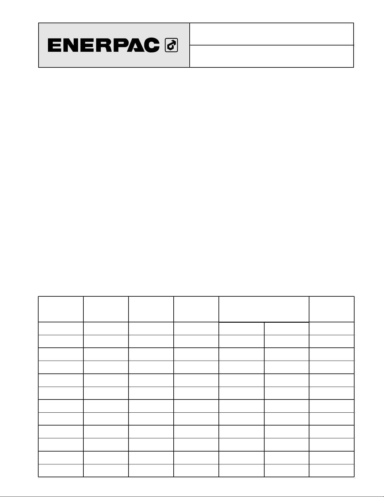
SPECIFICATIONS
Instruction Sheet
Work Supports
WFL / WSL 221, 222, 331, 332, 441, 442
MODEL
NUMBER
Capacity
@ Max. psi/bar
lbs.
(kN)
Support Plunger
Stroke
inches
(mm)
Retracted
Height
inches
(cm)
Plunger
Extended
Oil Capacity
inches
3
(cm3)
Support Plunger Spring Force
lbs. (kN)
Plunger
Retracted
WFL 221
5,000 0.41 3.61 1.0 - 3.25 .1916.0 - 23.0
WFL 222
(22,3) (10,4) (91,7) (4,4 - 14,0) (3,1)(71,0 - 102,0)
WFL 331
7,400 .53 3.87 2.0 - 6.0 .2416.0 - 19.0
WFL 332
(32,9) (13,5) (98,3) (9,0 - 26,0) (4,0)(71,0 - 84,0)
WFL 441
10,000 .65 4.42 1.5 - 5.0 .3016.0 - 28.0
WFL 442
(44,5) (16,5) (112,3) (6,7 - 22,0) (4,9)(71,0 - 124,0)
WSL 221
5,000 0.41 3.61 1.0 - 3.25 .0116.0 - 23.0
WSL 222
(22,3) (10,4) (91,7) (4,4 - 14,0) (0,2)(71,0 - 102,0)
WSL 331
7,400 .53 3.87 2.0 - 6.0 .0116.0 - 19.0
WSL 332
(32,9) (13,5) (98,3) (9,0 - 26,0) (0,2)(71,0 - 84,0)
WSL 441
10,000 65 4.42 1.5 - 5.0 .0116.0 - 28.0
WSL 442
(44,5) (16,5) (112,3) (6,7 - 22,0) (0,2)(71,0 - 124,0)
®
Page 2
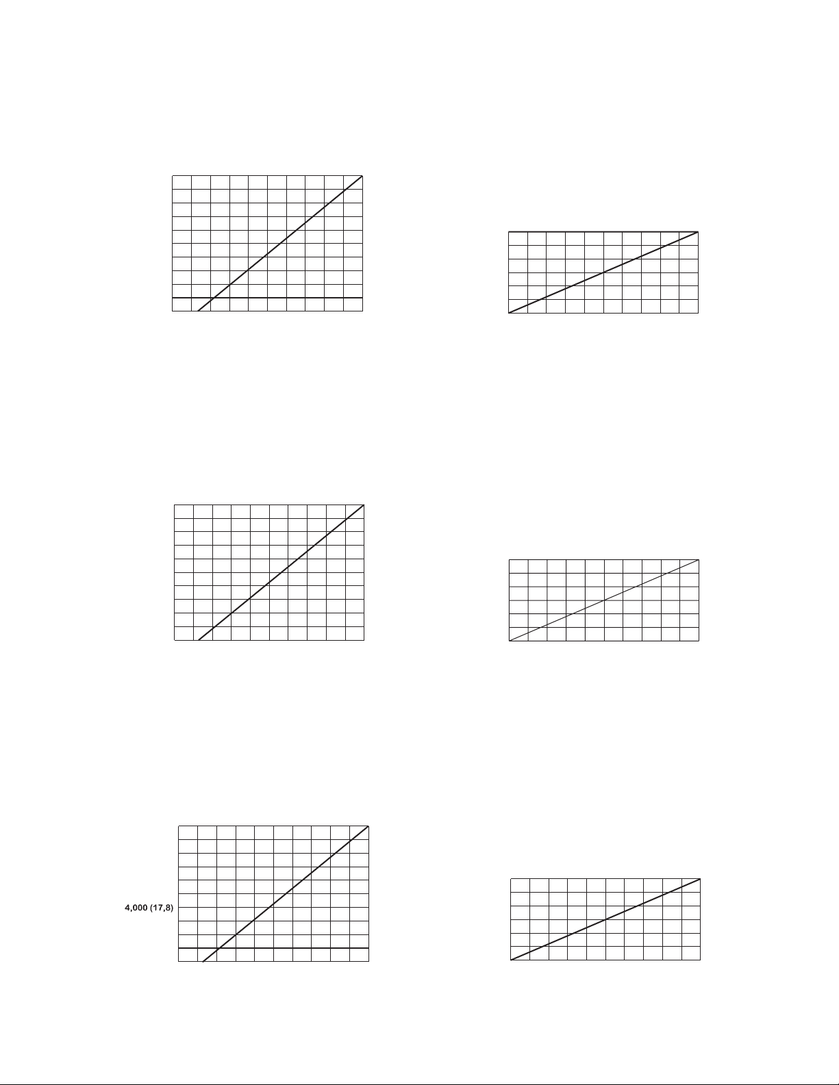
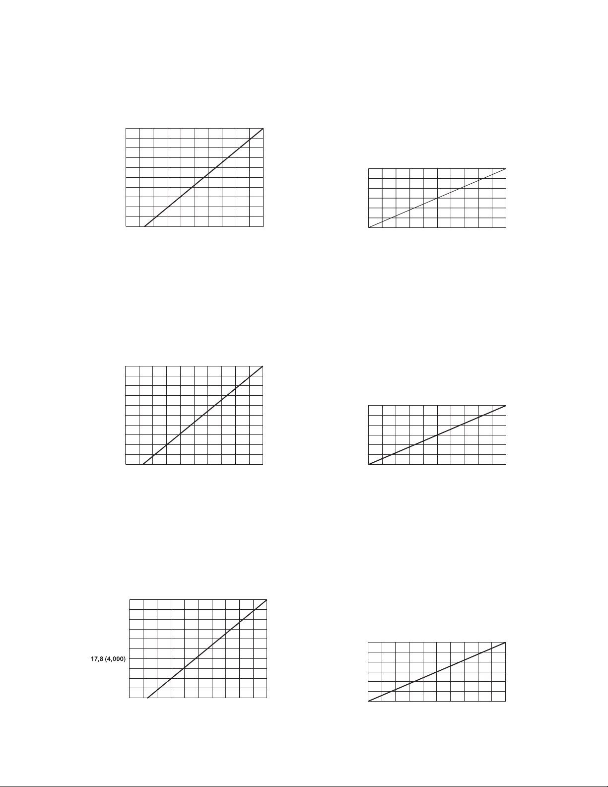
5,000 (22,3)
Maximum Holding Force
vs.
Hydraulic Operating Pressure
WFL / WSL 221, 222
Maximum Holding Force
lbs. (kN)
Support Plunger Deflection
vs.
Applied Load
at 5000 psi (350 bar)
Operating Pressure
WFL / WSL 221, 222
Elastic Deflection
inches (mm)
(2)
SPECIFICATIONS TABLE
Applied Load
lbs. (kN)
Operating Pressure
psi (bar)
Maximum Holding Force
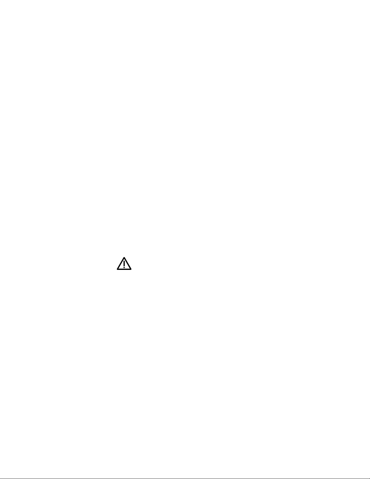
vs.
Hydraulic Operating Pressure
WFL / WSL 331,332
Maximum Holding Force
lbs. (kN)
Support Plunger Deflection
vs.
Applied Load
at 5000 psi (350 bar)
Operating Pressure
WFL / WSL 331, 332
Elastic Deflection
inches (mm)
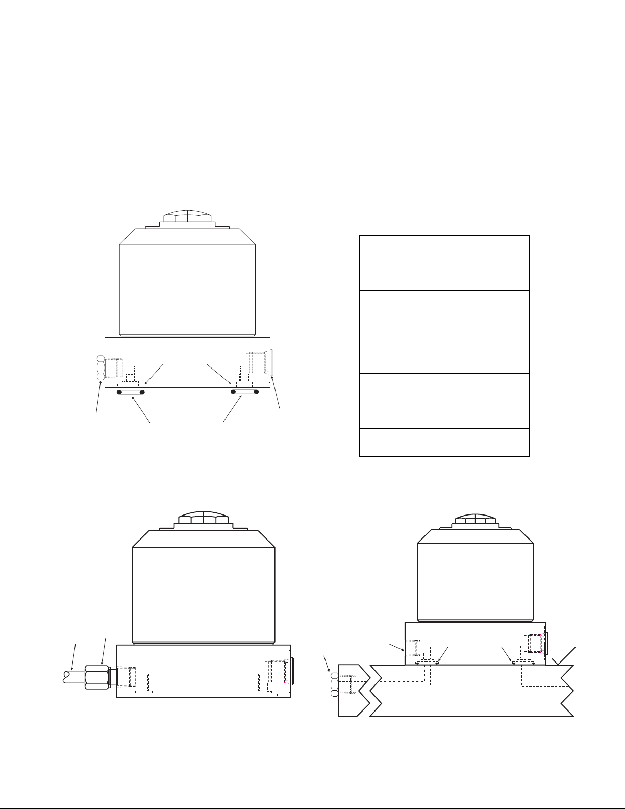
Maximum Holding Force
vs.
Hydraulic Operating Pressure
WFL / WSL 441, 442
Maximum Holding Force
lbs. (kN)
Support Plunger Deflection
vs.
Applied Load
at 5000 psi (350 bar)
Operating Pressure
WFL / WSL 441, 442
Elastic Deflection
inches (mm)
Applied Load
lbs. (kN)
Operating Pressure
psi (bar)
Applied Load
lbs. (kN)
Operating Pressure
psi (bar)
4,000 (17,8)
3,000 (13,4)
2,000 (8,90)
1,000 (4,45)
7,400 (32,9)
6,000 (26,7)
4,500 (20,0)
3,000 (13,3)
1,500 (6,7)
0
1,000
2,000
(70)
3,000 5,000
(140)
0
1,000
(70)
2,000
(140)
3,000
(210)
4,000
(280)(210)
(350)
5,0004,000
(280) (350)
.0030 (0,076)
.0025 (0,064)
.0020 (0,051)
.0015 (0,038)
.0010 (0,025)
.0005 (0,013)
0,076 (.0030)
0,064 (.0025)
0,051 (.0020)
0,038 (.0015)
0,025 (.0010)
0,013 (.0005)
0
0
1,000
2,000
3,000
(4,5)
(8,9)
(13,4)
4,000
(17,8)
13,4
4,5
(1,000)
8,9
(2,000)
(3,000)
17,8
(4,000)
5,000
(22,3)
22,3
(5,000)
10,000 (44,5)
8,000 (35,6)
6,000 (26,7)
2,000 (8,9)
0
2,0001,000 3,000 4,000 5,000
(210) (280) (350)
(140)
(70)
.0030 (0,076)
.0025 (0,064)
.0020 (0,051)
.0015 (0,038)
.0010 (0,025)
.0005 (0,013)
0
4,000
2,000 8,0006,000 10,000
(17,8)
(8,9)
(35,6)(26,7)
(44,5)
Page 3
SAFETY INFORMATION
To avoid personal injury during system operation, read and follow all CAUTIONS, WARNINGS,
and INSTRUCTIONS included with or attached to each product. ENERPAC CANNOT BE
RESPONSIBLE FOR DAMAGE RESULTING FROM UNSAFE USE OF PRODUCT, LACK OF
MAINTENANCE, OR INCORRECT PRODUCT OR SYSTEM APPLICATION. Contact Enerpac
when in doubt about applications and safety precautions.
WARNING
The system operating pressure must not exceed the
maximum pressure rating of the lowest rated component in the
system. Always check product limitations regarding pressure
ranges, load capacities, and set-up requirements. Personal injury
and/or equipment damage can occur if system operating pressure
exceeds the maximum pressure rating of system components.
WARNING
Always wear proper personal protective gear when operating
hydraulic equipment (i.e. safety glasses, gloves, etc.)
.
WARNING
Make sure that all system components are protected from
external sources of damage, such as excessive heat, flame, moving
machine parts, sharp edges, and corrosive chemicals.
WARNING
Do not exceed the specified maximum load on the support
plunger.
(3)
Page 4

INSTALLATION
Hydraulic Connections
1. Locate the work supports at the lowest point of the fixture's hydraulic system
to aid in bleeding. Work supports must be purged of air by cycling several
times and allowing air in the system to vent at the highest point in the system.
2. Install the work supports by either threading into the fixture, using the
accessory jam nuts, or bolting the flange onto the fixture. Mount the work
support so that the plunger is at the approximate middle of its stroke when
contacting the workpiece in the fixture.
3. Hydraulic connections can be made at the side port or at the manifold port.
If making hydraulic connections at the manifold port, the port screw plug and
copper gasket must first be removed from the hydraulic manifold port (item
D). Lightly lubricate the provided O-ring (item C) and install it in the
counterbore around the port prior to mounting and bolting down the work
support (see figure 3). Be sure that the O-ring does not get pinched or
damaged during this mounting as leakage could result. To ensure that the
manifold mounting does not leak, provide a fixture mounting surface with a
flatness within .003 inch (0,08 mm) and a surface roughness average (R
a
) not
to exceed 32 µin. (0,8 µm).
WARNING
The fixture manifold must be capable of withstanding
hydraulic pressure of 5000 psi (350 bar).
4. The hydraulic power pump should not exceed 5000 psi (350 bar) maximum.
Power pumps must be large enough to provide a usable oil supply for the
work supports, hoses, clamps, and all items in the system. Refer to
specifications table for maximum applied loads vs. operating pressure.
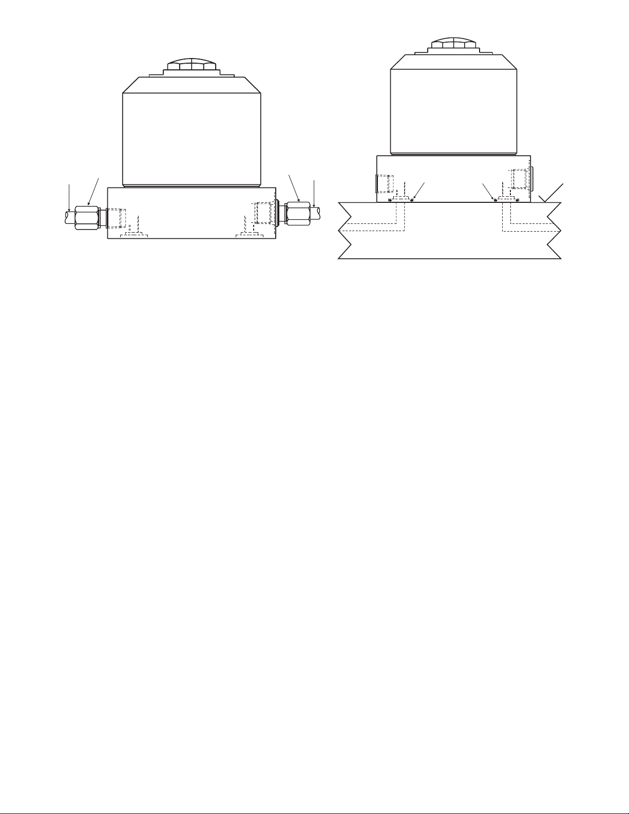
Venting
1. If the breather fitting (item A) is subject to a coolant flood condition, the
breather fitting should be removed. Use tubing and a threaded connector to
vent to a clean, remote area of the fixture (see figure 2).
2. Venting can also be achieved using the optional manifold breather port (see
figure 3).
2a. Remove the screw plug and copper gasket from the manifold breather
port (item B).
(4)
Page 5

2b. Lightly lubricate the provided O-Ring (item C) and install it in the
counterbore around the manifold breather port.
2c. Remove the breather fitting (item A) from the side breather port and
plug the port using a 1/8 NPT pipe plug.
2d. The breather fitting can be reused at a non-flooded area of the fixture.
(5)
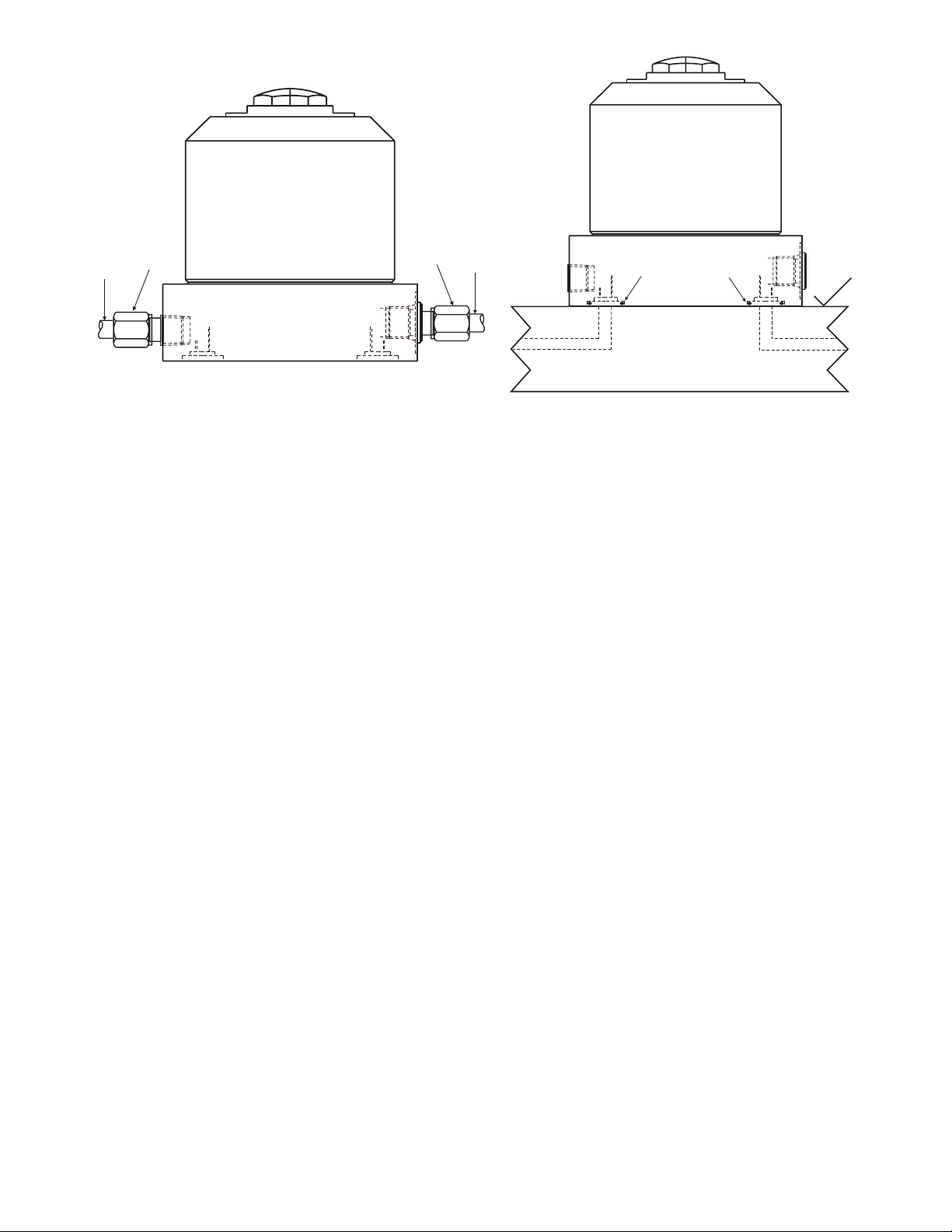
Figure 1 - Work Support
EEEE
Plug
Fitting
Tubing
Hydraulic Port
H
G
F
E
Manifold
Hydraulic Port
D
O-RingC
Manifold
Breather Port
B
Breather FittingA
Figure 2 - Venting Through Side Port
(Using additional tubing and fitting)
Figure 3 - Venting Through Manifold Port /
Hydraulic Manifold Mounting
B
A
C
D
E
C
G
F
H
CC
A
32
Page 6

MODIFICATIONS
"Air Purge" Work Supports
If the wiper area of the work support is exposed to coolant flooding or fine machining debris, the
work support should be modified to become an "air purge" work support. An "air purge" work
support allows air to blow through the wiper and prevents coolant and debris from entering the
work support.
1. Connect an air supply line (item F) to the side breather port (see figure 4) or
through manifold breather port (see figure 5). If connecting to the side
breather port, the breather fitting must first be removed. If connecting to the
manifold breather port, remove the screw plug and copper gasket from the
port, lightly lubricate the provided O-Ring, and install the O-Ring in the
counterbore around the port.
2. NOTE: The air purge only requires between 5-15 psi (0,3-1,0 bar) air
pressure.
"Air Spring" Work Supports
An "air spring" work support uses air, instead of a spring, to maintain the support plunger in an
extended position. An "air-spring" work support will not retract the plunger. (Note: Only spring
advanced work supports can be modified to become "air spring" work supports.) An "air spring"
work support can offer greater control over the force of the plunger against the workpiece. An
air spring work support can also provide more force against the plunger than conventional spring
advanced models.
1. Remove the contact bolt, adjustment screws and spring from within the work
support plunger.
2. After removing the spring, replace the nylon adjustment screw to seal the
threads. Also replace the contact bolt.
3. Connect an air supply line (item F) to the side breather port (see figure 4) or
through the manifold breather port (see figure 5). If connecting to the side
breather port, the breather fitting must first be removed. If connecting to the
manifold breather port, remove the screw plug and copper gasket from the
port, lightly lubricate the provided O-Ring, and install the O-Ring in the
counterbore around the port.
4. Add a two-position manual air valve or a solenoid operated air valve to the air
supply line.
(6)
Page 7
5. Use an air regulator (Enerpac RFL 102) to control air pressure. Excessive air
pressure may actually lift a work piece off of its rest surface. The correct
amount of air pressure will vary depending on the size and weight of the
workpiece and the work support.
OPERATION
Spring Advanced Work Supports
1. Adjust the contact force between the work support plunger and the workpiece.
1a. Remove the plastic adjustment screw from within the top of the
plunger.
1b. Turn the second adjustment screw clockwise to increase the contact
force. Turn the second adjustment screw counter clockwise to decrease
the contact force. Note: If the adjustment screw is backed out too far,
the plunger stroke will be reduced. Refer to specifications table for the
minimum and maximum contact force for each work support model.
1c. Replace the first adjustment screw. Make sure the first adjustment
screw is positioned snug against the second screw.
(7)
G
Figure 4 - "Air Purge" / "Air Spring" Work
Support using Side Breather Port
Figure 5 - "Air Purge" / "Air Spring" Work
Support using Manifold Breather Port
F
G
F
c
c
32
Page 8

2. Place the workpiece into the fixture and above the work supports. The
plunger should be at the approximate middle of its stroke when contacting the
workpiece. If the weight of the workpiece does not push the plunger down to
the proper height, repeat step 1 and adjust the contact force appropriately.
3. Activate hydraulic pressure to lock the work support plunger into position.
The position of the plunger will be maintained until hydraulic pressure is
released.
4. Clamp the workpiece into position to facilitate machining operations.
5. When machining is complete, release hydraulic pressure from clamping
cylinders first, then release hydraulic pressure from work supports.
6. Remove the workpiece from the fixture.
Fluid Advanced Work Supports
1. When no hydraulic pressure is applied, the plunger will be in the retract
position. Place the workpiece into the fixture and above the work supports.
The plunger should be at the approximate middle of its stroke when
contacting the workpiece.
2. Activate hydraulic pressure to advance the work support plunger into
position. When hydraulic pressure is applied, a piston pushes against an
internal spring that advances the plunger to the workpiece. As hydraulic
pressure increases, the compression sleeve grips and locks the plunger at the
point of contact. The position of the plunger will be maintained until
hydraulic pressure is released.
3. Clamp the workpiece into position to facilitate machining operations.
4. When machining is complete, release hydraulic pressure from clamping
cylinders first, then release hydraulic pressure from work supports.
5. Remove the workpiece from the fixture.
"Air Spring" Work Supports
1. Set the air regulator to the correct air pressure. The correct pressure will vary
depending on the size of the work support and the weight of the workpiece.
2. When no air pressure is applied, the plunger will be in the retract position.
Place the workpiece into the fixture and above the work supports.
(8)
Page 9

3. Shift the handle of the air valve to activate air pressure and advance the work
support plunger into position. The plunger should be at the approximate
middle of its stroke when contacting the workpiece. If the weight of the
workpiece does not push the plunger down to the correct position, repeat step
1 and adjust the air pressure appropriately
4. Activate hydraulic pressure to lock the work support plunger into position.
The position of the plunger will be maintained until hydraulic pressure is
released.
5. Clamp the workpiece into position to facilitate machining operations.
6. When machining is complete, release hydraulic pressure from clamping
cylinders first, then release hydraulic pressure from work supports.
7. Remove workpiece from the fixture.
MAINTENANCE AND SERVICE
Maintenance is required only when wear and/or leakage is noticed. Occasionally,
inspect all components to detect any problems requiring service and maintenance.
Enerpac offers repair kits for equipment maintenance. Repair parts sheets are also
available. Contact your Enerpac representative.
TROUBLESHOOTING
(9)
Check seals for wear or damage.
Connection to work supports may be leaking.
Work support leaks oil.
Hydraulic pressure has not been released from the
system.
Excessive back pressure from small diameter tubing or
tight bends.
Check plunger and sleeve for damage or for debris
accumulation.
Check for broken return spring.
Plunger will not retract.
Plunger will not release to extended height.
Hydraulic pressure may be below minimum amount to
hold plunger.
Cutting forces may be exceeding the capacity of the work
support.
The workpiece is experiencing excessive deflection.
Determine if hydraulic system is exceeding maximum flow
rate (see specifications table).
Check for broken take up spring.
Check plunger and sleeve for damage.
Plunger will not advance when system pressure is
activated.
POSSIBLE CAUSEPROBLEM
Page 10

(10)
Page 11

L 2216 Rev. O 05/97
WICHTIGE ANWEISUNGEN FÜR DIE EINGANGSKONTROLLE
Unterziehen Sie alle Teile einer Sichtkontrolle auf eventuelle Transportschäden.
Wird ein solcher Transportschaden festgestellt, benachrichtigen Sie unverzüglich
den Spediteur. Transportschäden sind von der Gewährleistung NICHT abgedeckt.
Der Spediteur haftet für alle Reparatur- und Austauschkosten, die sich aus einer
Beschädigung beim Transport ergeben.
INHALTSVERZEICHNIS
Technische Daten ...........................................................................11
Sicherheitsinformationen ...............................................................13
Installation
Hydraulikanschlüsse ...............................................................14
Entlüftung ...............................................................................14
Modifizierungen
Abstützzylinder mit „Luftspülung".........................................16
Abstützzylinder mit „Luftfederung".......................................16
Betrieb
Federanstellbare Abstützzylinder............................................17
Hydraulisch anstellbare Abstützzylinder................................18
Abstützzylinder mit „Luftfederung".......................................18
Wartung und Reparatur ..................................................................19
Störungssuche ................................................................................19
TECHNISCHE DATEN
Bedienungsanleitung
Abstützzylinder
WFL/WSL 221, 222, 331, 332, 441, 442
MODELLNUMMER
Zylinderkraft bei
max. psi/bar
lb
(kN)
Hub des
Abstützkolbens
Inch
(mm)
Eingefahrene
Höhe
Inch
(cm)
Ausgefahrener
Kolben
Ölfassungs-
vermögen
Inch
3
(cm3)
Federdruck des Abstützkolbens
lb (kN)
Eingefahrener
Kolben
WFL 221
5,000 0.41 3.61 1.0 - 3.25 .1916.0 - 23.0
WFL 222
(22,3) (10,4) (91,7) (4,4 - 14,0) (3,1)(71,0 - 102,0)
WFL 331
7,400 .53 3.87 2.0 - 6.0 .2416.0 - 19.0
WFL 332
(32,9) (13,5) (98,3) (9,0 - 26,0) (4,0)(71,0 - 84,0)
WFL 441
10,000 .65 4.42 1.5 - 5.0 .3016.0 - 28.0
WFL 442
(44,5) (16,5) (112,3) (6,7 - 22,0) (4,9)(71,0 - 124,0)
WSL 221
5,000 0.41 3.61 1.0 - 3.25 .0116.0 - 23.0
WSL 222
(22,3) (10,4) (91,7) (4,4 - 14,0) (0,2)(71,0 - 102,0)
WSL 331
7,400 .53 3.87 2.0 - 6.0 .0116.0 - 19.0
WSL 332
(32,9) (13,5) (98,3) (9,0 - 26,0) (0,2)(71,0 - 84,0)
WSL 441
10,000 65 4.42 1.5 - 5.0 .0116.0 - 28.0
WSL 442
(44,5) (16,5) (112,3) (6,7 - 22,0) (0,2)(71,0 - 124,0)
®
Page 12
22,3 (5,000)
Maximale Haltekraft
relativ zum
hydraulischen Betriebsdruck
WFL/WSL 221, 222
Maximale Haltekraft
kN (lb)
Abstützkolben-Verformung
relativ zur
eingesetzten Belastung
bei 350 bar (5000 psi)
Betriebsdruck
WFL/WSL 221, 222
Elastische Verformung
mm (Inch)
(12)
TECHNISCHE DATEN
Eingesetzte Belastung
kN (lb)
Betriebsdruck
bar (psi)
Maximale Haltekraft
relativ zum
hydraulischen Betriebsdruck
WFL/WSL 331, 332
Maximale Haltekraft
kN (lb)
Abstützkolben-Verformung
relativ zur
eingesetzten Belastung
bei 350 bar (5000 psi)
Betriebsdruck
WFL/WSL 331, 332
Elastische Verformung
mm (Inch)
Eingesetzte Belastung
kN (lb)
Betriebsdruck
bar (psi)
Maximale Haltekraft
relativ zum
hydraulischen Betriebsdruck
WFL/WSL 441, 442
Maximale Haltekraft
kN (lb)
Abstützkolben-Verformung
relativ zur
eingesetzten Belastung
bei 350 bar (5000 psi)
Betriebsdruck
WFL/WSL 441, 442
Elastische Verformung
mm (Inch)
Eingesetzte Belastung
kN (lb)
Betriebsdruck
bar (psi)
17,8 (4,000)
13,4 (3,000)
8,90 (2,000)
4,45 (1,000)
0
(1,000)
32,9 (7,400)
26,7 (6,000)
20,0 (4,500)
13,3 (3,000)
6,7 (1,500)
0
(1,000) (3,000) (5,000)(4,000)
70 140 210 280 350
(2,000)
(4,000)(3,000) (5,000)
70 140 210 280 350
(2,000)
0,076 (.0030)
0,064 (.0025)
0,051 (.0020)
0,038 (.0015)
0,025 (.0010)
0,013 (.0005)
0,076 (.0030)
0,064 (.0025)
0,051 (.0020)
0,038 (.0015)
0,025 (.0010)
0,013 (.0005)
0
4,5
(2,000)
(1,000)
8,9
13,4
(3,000)
13,3
6,7
0
(1,500)
(3,000)
20,0 26,7 32,9
(4,500) (6,000) (7,400)
17,8
(4,000)
22,3
(5,000)
44,5 (10,000)
35,6 (8,000)
26,7 (6,000)
8,9 (2,000)
0
(1,000) (2,000) (3,000) (4,000) (5,000)
70 140 210 280 350
0,076 (.0030)
0,064 (.0025)
0,051 (.0020)
0,038 (.0015)
0,025 (.0010)
0,013 (.0005)
0
8,9 17,8 26,7 35,6 44,5
(2,000) (4,000) (6,000) (8,000) (10,000)
Page 13

SICHERHEITSINFORMATIONEN
Um Verletzungen während des Systembetriebs zu vermeiden, lesen und befolgen Sie bitte alle
VORSICHTS- und WARNUNGS-Hinweise sowie die ANWEISUNGEN, die jedem Produkt beiliegen
oder daran angebracht sind. ENERPAC HAFTET NICHT FÜR SCHÄDEN, DIE AUF
FAHRLÄSSIGEN GEBRAUCH DES PRODUKTS, MANGELHAFTE INSTANDHALTUNG ODER
UNSACHGEMÄSSE PRODUKT- UND SYSTEMANWENDUNG ZURÜCKZUFÜHREN SIND.
Wenden Sie sich an Enerpac, sofern Sie Fragen zur Produktanwendung oder zu den
Sicherheitsmaßnahmen haben.
WARNUNG
Der Systembetriebsdruck darf nicht höher sein als der
Nennbetriebsdruck der Systemkomponente mit dem niedrigsten
Nenndruck. Die Grenzen des Produkts in bezug auf Druckbereich,
Belastbarkeit und die Anforderungen bei der Einstellung sind auf
jeden Fall zu beachten. Wenn der Systembetriebsdruck den
Nennbetriebsdruck von Systemkomponenten überschreitet, kann
dies zu Verletzungen und/oder Sachschäden führen.
WARNUNG
Um Verletzungen zu vermeiden, tragen Sie beim Bedienen
hydraulischer Geräte bitte stets zweckmäßige Schutzkleidung,
(d.h. Schutzbrille, Schutzhandschuhe usw.).
WARNUNG
Stellen Sie sicher, daß die Systemkomponenten keinen
schädlichen Außeneinwirkungen wie übermäßiger Hitze,
offenem Feuer, beweglichen Maschinenteilen, scharfen
Gegenständen und korrodierenden Chemikalien ausgesetzt sind.
WARNUNG
Die angegebene maximale Belastung des Abstützkolbens
nicht überschreiten.
(13)
Page 14
INSTALLATION
Hydraulikanschlüsse
1. Die Abstützzylinder am niedrigsten Punkt des Hydrauliksystems der
Vorrichtung anbringen, um die Entlüftung zu vereinfachen. Um die
Abstützzylinder zu entlüften, müssen sie mehrmals betrieben werden, damit
die Luft am höchsten Punkt des Systems entweichen kann.
2. Zum Anbringen der Abstützzylinder diese entweder mit den ZubehörGegenmuttern in die Vorrichtung schrauben oder den Flansch an der
Vorrichtung festschrauben. Den Abstützzylinder so montieren, daß der
Kolben bei Berührung mit dem Werkstück in der Vorrichtung etwa halb
ausgefahren ist.
3. Die Hydraulikanschlüsse können am seitlichen Anschluß oder am Anschluß
des Verteilerrohrs vorgenommen werden. Falls die Hydraulikanschlüsse am
Anschluß des Verteilerrohrs vorgenommen werden, müssen zuerst die
Verschlußschraube und die Dichtung aus Kupfer vom Anschluß entfernt
werden (D). Den mitgelieferten O-Ring (C) leicht einfetten und in der
Senkung um den Anschluß anbringen, bevor der Abstützzylinder montiert und
festgeschraubt wird (siehe Abbildung 3). Darauf achten, daß der O-Ring beim
Einbau nicht gequetscht oder beschädigt wird, da es andernfalls zu
Undichtheiten kommt. Um zu gewährleisten, daß die Befestigungsstelle am
Verteilerrohr nicht undicht ist, sicherstellen, daß die Anlagefläche der
Vorrichtung innerhalb einer Toleranz von 0,08 mm (0.003 Inch) eben ist und
daß die Oberflächenrauheit (R
a
)weniger als 0,8 µm (32 µInch) beträgt.
WARNUNG
Das Verteilerrohr der Vorrichtung muß für einen
Hydraulikdruck von 350 bar (5000 psi) ausgelegt sein.
4. Die Hydraulikpumpe sollte auf einen Druck von 350 bar (5000 psi)
beschränkt sein. Die Hydraulikpumpen müssen leistungsfähig genug sein, um
die notwendige Ölzufuhr für die Abstützzylinder, Schläuche, Schellen und
alle Geräte im System liefern zu können. Siehe die Tabelle mit den
technischen Daten für die maximale Belastung relativ zum Betriebsdruck.
Entlüftung
1. Falls die Gefahr besteht, daß das Entlüfteranschlußstück (A) mit Kühlmittel
überspült wird, sollte das Entlüfteranschlußstück entfernt werden. Die
Entlüftung mit einem Rohr und einer Verschraubung an einen sauberen,
entfernten Bereich der Vorrichtung verlegen (siehe Abbildung 2).
2. Zur Entlüftung kann auch der als Sonderzubehör erhältliche VerteilerrohrEntlüftungsanschluß (siehe Abbildung 3) verwendet werden.
(14)
Page 15
2a. Die Verschlußschraube und die Dichtung aus Kupfer vom
Entlüftungsanschluß des Verteilerrohrs (B) entfernen.
2b. Den mitgelieferten O-Ring (C) leicht einfetten und in der Senkung um
den Entlüftungsanschluß des Verteilerrohrs anbringen.
2c. Das Entlüfteranschlußstück (A) vom seitlichen Entlüftungsanschluß
entfernen und den Anschluß mit einem 1/8 NPT Stopfen verschließen.
2d. Das Entlüfteranschlußstück kann in einem Bereich der Vorrichtung
wiederverwendet werden, an dem keine Gefahr der Überspülung
besteht.
(15)
Abbildung 1 - Abstützzylinder
EEEE
Stopfen
Verschraubung
Rohr
Hydraulikanschluß
H
G
F
E
Verteilerrohr-
Hydraulikanschluß
D
O-RingC
Verteilerrohr-
Entlüftungsanschluß
B
EntlüfteranschlußstückA
Abbildung 2 - Entlüftung durch den
seitlichen Anschluß (mit zusätzlichem
Rohr und einer Verschraubung)
Abbildung 3 - Entlüftung durch den
Verteilerrohr-Anschluß / Befestigung des
Hydraulik-Verteilerrohrs
B
A
C
D
C
E
G
F
H
CC
A
0,8
Page 16

MODIFIZIERUNGEN
Abstützzylinder mit „Luftspülung"
Falls die Gefahr besteht, daß der Abstreicherbereich des Abstützzylinders mit Kühlmittel
überspült oder feinem Maschinenstaub ausgesetzt sein könnte, sollte der Abstützzylinder auf
„Luftspülung" umgestellt werden. Bei einem Abstützzylinder mit „Luftspülung" wird Luft durch
den Abstreicher geblasen, wodurch das Eintreten von Kühlmittel und Staub in den
Abstützzylinder verhindert wird.
1. Eine Luftdruckleitung (F) an den seitlichen Entlüftungsanschluß (siehe
Abbildung 4) oder an den Verteilerrohr-Entlüftungsanschluß (siehe Abbildung
5) anschließen. Falls die Leitung an den seitlichen Entlüftungsanschluß
angeschlossen wird, muß zunächst das Entlüfteranschlußstück entfernt
werden. Falls die Leitung an den Verteilerrohr-Entlüftungsanschluß
angeschlossen wird, die Verschlußschraube und die Dichtung aus Kupfer vom
Anschluß entfernen, den mitgelieferten O-Ring leicht einfetten und den ORing in der Senkung um den Anschluß anbringen.
2. HINWEIS: Für die Luftspülung ist ein Druck von nur 0,3-1,0 bar (5-15 psi)
erforderlich.
Abstützzylinder mit „Luftfederung"
Bei einem Abstützzylinder mit „Luftfederung" wird Luft an Stelle einer Feder verwendet, um
den Abstützkolben in ausgefahrener Stellung zu halten. Bei einem Abstützzylinder mit
„Luftfederung" kann der Abstützkolben nicht eingezogen werden. (Hinweis: Nur
federanstellbare Abstützzylinder können auf „Luftfederung" umgestellt werden.) Ein
Abstützzylinder mit „Luftfederung" ermöglicht größere Kontrolle über die Kraft, mit der der
Abstützkolben gegen das Werkstück gedrückt wird. Bei einem Abstützzylinder mit
„Luftfederung" kann außerdem mehr Kraft am Abstützkolben angesetzt werden, als bei
Modellen mit herkömmlicher Federanstellung.
1. Die Kontaktschraube, Stellschrauben und die Feder aus dem Abstützkolben
entfernen.
2. Nachdem die Feder entfernt wurde, die Nylon-Stellschraube zum Abdichten
des Gewindes wieder einsetzen. Die Kontaktschraube ebenfalls wieder
einsetzen.
3. Eine Luftdruckleitung (F) an den seitlichen Entlüftungsanschluß (siehe
Abbildung 4) oder an den Verteilerrohr-Entlüftungsanschluß (siehe Abbildung
5) anschließen. Falls die Leitung an den seitlichen Entlüftungsanschluß
angeschlossen wird, muß zunächst das Entlüfteranschlußstück entfernt
werden. Falls die Leitung an den Verteilerrohr-Entlüftungsanschluß
angeschlossen wird, die Verschlußschraube und die Dichtung aus Kupfer vom
Anschluß entfernen, den mitgelieferten O-Ring leicht einfetten und den ORing in der Senkung um den Anschluß anbringen.
(16)
Page 17
4. Die Druckluftleitung mit
einem handbetriebenen Zweiwege-Luftventil oder einem Magnetluftventil
ausstatten.
5. Zur Steuerung des Luftdrucks ein Luftregulierventil (Enerpac RFL 102)
verwenden. Übermäßiger Luftdruck kann dazu führen, daß ein Werkstück
regelrecht abhebt. Der notwendige Luftdruck hängt von der Größe und dem
Gewicht des Werkstückes und des Abstützzylinders ab.
BETRIEB
Federanstellbare Abstützzylinder
1. Die Kraft, mit der der Abstützkolben auf das Werkstück drückt, einstellen.
1a. Die Stellschraube aus Kunststoff oben aus dem Abstützkolben
entfernen.
1b. Die zweite Stellschraube im Uhrzeigersinn drehen, um den Druck zu
vergrößern. Die zweite Stellschraube gegen den Uhrzeigersinn drehen,
um den Druck zu verringern. Hinweis: Wird die Stellschraube zu weit
herausgeschraubt, führt dies zu einer Verkürzung des Abstützkolbenhubs. Siehe die technischen Daten für den Mindest- und
Höchstdruck für das jeweilige Abstützzylinder-Modell.
1c. Die erste Stellschraube wieder einsetzen. Sicherstellen, daß die erste
Stellschraube satt an der zweiten Stellschraube anliegt.
(17)
G
Abbildung 4 - Abstützzylinder mit
„Luftspülung" / „Luftfederung" bei
Verwendung des seitlichen
Entlüftungsanschlusses
Abbildung 5 - Abstützzylinder mit
„Luftspülung" / „Luftfederung" bei
Verwendung des Verteilerrohr-
Entlüftungsanschlusses
F
G
F
c
c
0,8
Page 18

2. Das Werkstück über den Abstützzylindern in die Vorrichtung einsetzen. Der
Abstützkolben sollte etwa halb ausgefahren sein, wenn er das Werkstück
berührt. Falls das Gewicht des Werkstückes nicht ausreicht, um den
Abstützkolben auf die gewünschte Höhe niederzudrücken, den ersten Schritt
wiederholen und den Druck ordnungsgemäß einstellen.
3. Den Hydraulikdruck einstellen, um den Abstützkolben einzurasten. Die
Abstützkolbenstellung wird beibehalten, bis der Hydraulikdruck
abgelassen wird.
4. Das Werkstück festklemmen, um die Bearbeitung zu vereinfachen.
5. Wenn die Bearbeitung abgeschlossen ist, den Hydraulikdruck zuerst aus den
Spannzylindern und dann aus den Abstützzylindern ablassen.
6. Das Werkstück von der Vorrichtung entfernen.
Hydraulisch anstellbare Abstützzylinder
1. Wenn kein Hydraulikdruck anliegt, befindet sich der Abstützkolben in
eingefahrener Stellung. Das Werkstück über den Abstützzylindern in die
Vorrichtung einsetzen. Der Abstützkolben sollte etwa halb ausgefahren sein,
wenn er das Werkstück berührt.
2. Den Hydraulikdruck einstellen, um den Abstützkolben auszufahren. Wenn der
Hydraulikdruck anliegt, drückt ein Kolben gegen eine Feder im Inneren, die
den Abstützkolben gegen das Werkstück ausfährt. Bei steigendem
Hydraulikdruck greift die Klemmhülse und der Abstützkolben wird an der
Stelle, an der er das Werkstück berührt, verriegelt. Die Abstützkolbenstellung
wird beibehalten, bis der Hydraulikdruck abgelassen wird.
3. Das Werkstück festklemmen, um die Bearbeitung zu vereinfachen.
4. Wenn die Bearbeitung abgeschlossen ist, den Hydraulikdruck zuerst aus den
Spannzylindern und dann aus den Abstützzylindern ablassen.
5. Das Werkstück von der Vorrichtung entfernen.
Abstützzylinder mit „Luftfederung"
1. Das Luftregulierventil auf den entsprechenden Luftdruck einstellen. Der
notwendige Druck hängt von der Größe des Abstützzylinders und dem
Gewicht des Werkstücks ab.
2. Wenn kein Luftdruck anliegt, befindet sich der Abstützkolben in
eingefahrener Stellung. Das Werkstück über den Abstützzylindern in die
Vorrichtung einsetzen.
(18)
Page 19

3. Den Griff am Luftventil einstellen, um den Luftdruck anzulegen und den
Abstützkolben auszufahren. Der Abstützkolben sollte etwa halb ausgefahren
sein, wenn er das Werkstück berührt. Falls das Gewicht des Werkstückes nicht
ausreicht, um den Abstützkolben auf die passende Höhe niederzudrücken, den
ersten Schritt wiederholen und den Luftdruck ordnungsgemäß einstellen.
4. Den Hydraulikdruck einstellen, um den Abstützkolben einzurasten. Die
Abstützkolbenstellung wird beibehalten, bis der Hydraulikdruck abgelassen
wird.
5. Das Werkstück festklemmen, um die Bearbeitung zu vereinfachen.
6. Wenn die Bearbeitung abgeschlossen ist, den Hydraulikdruck zuerst aus den
Spannzylindern und dann aus den Abstützzylindern ablassen.
7. Das Werkstück aus der Vorrichtung entfernen.
WARTUNG UND REPARATUR
Die Abstützzylinder müssen nur gewartet werden, falls Abnutzung bzw.
Undichtheiten festgestellt werden. Von Zeit zu Zeit sollten alle Komponenten
geprüft werden, um jegliche Probleme festzustellen, die der Reparatur oder
Wartung bedürfen. Enerpac bietet Reparatursätze für die Wartung an. Außerdem
sind Ersatzteillisten erhältlich. Bitte wenden Sie sich an Ihren Enerpac-Vertreter.
STÖRUNGSSUCHE
(19)
Dichtungen auf Abnutzung oder Beschädigung untersuchen.
Der Anschluß an die Abstützzylinder ist möglicherweise undicht.
Abstützzylinder leckt Öl.
Der Hydraulikdruck wurde nicht aus dem System entlassen.
Zu hoher Rückstau durch Rohre mit kleinem Durchmesser oder
zu engen Biegungen.
Den Abstützkolben und die Hülse auf Beschädigung bzw.
Rückstände untersuchen.
Prüfen, ob Rückpreßfeder gebrochen ist.
Der Abstützkolben fährt nicht ein.
Der Abstützkolben löst sich nicht in die ausgefahrene Höhe.
Möglicherweise ist der Hydraulikdruck geringer als der zum
Halten des Abstützkolbens notwendige Mindestdruck.
Die Schnittkraft übersteigt möglicherweise die Leistungsfähigkeit
des Abstützzylinders.
Das Werkstück wird übermäßiger Durchbiegung ausgesetzt.
Feststellen, ob vom Hydrauliksystem die maximale Durchflußrate
(siehe technische Daten) überschritten wird.
Prüfen, ob Kompensationsfeder gebrochen ist.
Den Abstützkolben und die Hülse auf Beschädigung
untersuchen.
Abstützkolben fährt nicht aus, wenn der Systemdruck aufgebaut
wird.
MÖGLICHE URSACHEPROBLEM
Page 20

(20)
Page 21

L 2216 Rév. O 05/97
INSTRUCTIONS IMPORTANTES POUR LA RÉCEPTION
Inspecter toutes les pièces en vue de dommages subis pendant l'expédition.
Signaler immédiatement au transporteur les dommages constatés. Les dommages
survenus pendant l'expédition NE SONT PAS couverts par la garantie. Le
transporteur est responsable de tous les frais de réparation et de remplacement
résultant de dégâts occasionnés durant l'expédition.
TABLE DES MATIÈRES
Caractéristiques..............................................................................21
Informations pour la sécurité .........................................................23
Installation
Branchements hydrauliques....................................................24
Aération...................................................................................24
Modifications
Supports de travail à «purge d'air» .........................................26
Supports de travail à «ressort pneumatique»..........................26
Utilisation
Supports de travail à extension par ressort.............................27
Supports de travail à extension hydraulique...........................28
Supports de travail à «ressort pneumatique»..........................28
Entretien et dépannage...................................................................29
Dépannage......................................................................................29
CARACTÉRISTIQUES
Notice d'emploi
Supports de travail
WFL/WSL 221, 222, 331, 332, 441, 442
N° DE
MODÈLE
Capacité à la
pression max.
lb
(kN)
Course de la
tige du vérin
pouces
(mm)
Hauteur
rétracté
pouces
(cm)
Tige du vérin
étendue
Contenance
en huile
pouces
3
(cm3)
Force de ressort de la tige
du vérin lb (kN)
Tige du vérin
rétractée
WFL 221
5,000 0.41 3.61 1.0 - 3.25 .1916.0 - 23.0
WFL 222
(22,3) (10,4) (91,7) (4,4 - 14,0) (3,1)(71,0 - 102,0)
WFL 331
7,400 .53 3.87 2.0 - 6.0 .2416.0 - 19.0
WFL 332
(32,9) (13,5) (98,3) (9,0 - 26,0) (4,0)(71,0 - 84,0)
WFL 441
10,000 .65 4.42 1.5 - 5.0 .3016.0 - 28.0
WFL 442
(44,5) (16,5) (112,3) (6,7 - 22,0) (4,9)(71,0 - 124,0)
WSL 221
5,000 0.41 3.61 1.0 - 3.25 .0116.0 - 23.0
WSL 222
(22,3) (10,4) (91,7) (4,4 - 14,0) (0,2)(71,0 - 102,0)
WSL 331
7,400 .53 3.87 2.0 - 6.0 .0116.0 - 19.0
WSL 332
(32,9) (13,5) (98,3) (9,0 - 26,0) (0,2)(71,0 - 84,0)
WSL 441
10,000 65 4.42 1.5 - 5.0 .0116.0 - 28.0
WSL 442
(44,5) (16,5) (112,3) (6,7 - 22,0) (0,2)(71,0 - 124,0)
®
Page 22

Force de rétention maximum
et
Pression hydraulique de fonctionnement
WFL/WSL 221, 222
Force de rétention maximum
kN (lb)
Déflexion de la tige du vérin
et
Force appliquée
à pression de fonctionnement
de 350 bar (5000 psi)
WFL/WSL 221, 222
Flexion élastique
mm (pouces)
(22)
TABLEAU DES CARACTÉRISTIQUES
Force appliquée
kN (lb)
Pression de fonctionnement
bar (psi)
Force de rétention maximum
et
Pression hydraulique de fonctionnement
WFL/WSL 331, 332
Force de rétention maximum
kN (lb)
Déflexion de la tige du vérin
et
Force appliquée
à pression de fonctionnement
de 350 bar (5000 psi)
WFL/WSL 331, 332
Flexion élastique
mm (pouces)
Force appliquée
kN (lb)
Pression de fonctionnement
bar (psi)
Force de rétention maximum
et
Pression hydraulique de fonctionnement
WFL/WSL 441, 442
Force de rétention maximum
kN (lb)
Déflexion de la tige du vérin
et
Force appliquée
à pression de fonctionnement
de 350 bar (5000 psi)
WFL/WSL 441, 442
Flexion élastique
mm (pouces)
Force appliquée
kN (lb)
Pression de fonctionnement
bar (psi)
22,3 (5,000)
17,8 (4,000)
13,4 (3,000)
8,90 (2,000)
4,45 (1,000)
0
70 140 210 280 350
(1,000)
32,9 (7,400)
26,7 (6,000)
20,0 (4,500)
13,3 (3,000)
6,7 (1,500)
0
70 140 210 280 350
(1,000) (3,000) (5,000)(4,000)
(2,000)
(2,000)
(4,000)(3,000) (5,000)
0,076 (.0030)
0,064 (.0025)
0,051 (.0020)
0,038 (.0015)
0,025 (.0010)
0,013 (.0005)
0,076 (.0030)
0,064 (.0025)
0,051 (.0020)
0,038 (.0015)
0,025 (.0010)
0,013 (.0005)
0
0
13,4
17,8
4,5
(1,000)
8,9
(2,000)
(3,000)
(4,000)
22,3
(5,000)
13,3
6,7
(1,500)
(3,000)
20,0 26,7 32,9
(4,500) (6,000) (7,400)
44,5 (10,000)
35,6 (8,000)
26,7 (6,000)
8,9 (2,000)
0
70 140 210 280 350
(1,000) (2,000) (3,000) (4,000) (5,000)
0,076 (.0030)
0,064 (.0025)
0,051 (.0020)
0,038 (.0015)
0,025 (.0010)
0,013 (.0005)
0
8,9 17,8 26,7 35,6 44,5
(2,000) (4,000) (6,000) (8,000) (10,000)
Page 23

INFORMATIONS POUR LA SÉCURITÉ
Pour éviter les accidents corporels pendant le fonctionnement du système, lire et respecter toutes les
MISES EN GARDE, AVERTISSEMENTS et INSTRUCTIONS accompagnant ou apposés sur chaque
produit. ENERPAC DÉCLINE TOUTE RESPONSABILITÉ EN CAS DE DOMMAGES MATÉRIELS
OU PERSONNELS RÉSULTANT D'UN USAGE DANGEREUX DU PRODUIT, D'UN MANQUE
D'ENTRETIEN OU DE L'USAGE INCORRECT DU PRODUIT OU DU SYSTÈME. En cas de doute
en ce qui concerne les applications ou les mesures de sécurité, contacter Enerpac.
AVERTISSEMENT
La pression de fonctionnement du système ne doit pas
dépasser la valeur de pression nominale maximale du composant
du système ayant la valeur la plus faible. Toujours consulter les
limites de plages de pression, capacités de charge et conditions
d'installation. Une pression de fonctionnement supérieure à la
pression nominale maximum des composants du système peut
résulter en des blessures ou des dommages matériels.
AVERTISSEMENT
Toujours porter un équipement de protection personnelle
adéquat pendant l'utilisation du matériel hydraulique (lunettes de
protection, gants, etc.).
AVERTISSEMENT
S'assurer que tous les composants sont protégés des
sources de dommages externes telles que chaleur excessive,
flammes, pièces mobiles, bords coupants, produits chimiques
corrosifs.
AVERTISSEMENT
Ne pas dépasser la charge maximum spécifiée sur la tige de
vérin du support.
(23)
Page 24

INSTALLATION
Branchements hydrauliques
1. Placer le support de travail au point le plus bas du circuit hydraulique de la
machine pour faciliter la purge. Les supports de travail doivent être purgés par
plusieurs actionnements successifs pour permettre à l'air du circuit de
s'échapper à son point le plus haut.
2. Pour installer les supports, les visser sur la machine, utiliser les écrous de
blocage ou boulonner la bride sur la machine. Monter le support de travail de
façon à ce que la tige du vérin soit approximativement à mi-course lorsqu'elle
entre en contact avec la pièce à usiner dans la machine.
3. Les branchements hydrauliques peuvent se faire sur l'orifice latéral ou sur
celui du bloc foré. Si les branchements sont effectués sur l'orifice du bloc
foré, le bouchon fileté et le joint en cuivre doivent d'abord être retirés de
l'orifice (article D). Lubrifier légèrement le joint torique (article C) fourni et
l'installer dans la noyure du pourtour de l'orifice avant de monter et de
boulonner le support de travail (voir la figure 3). Veiller à ce que le joint
torique ne soit ni pincé ni endommagé durant le montage car des fuites
pourraient se produire. Pour s'assurer que le bloc foré ne présente pas de
fuites, la tolérance de planéité de la surface de montage de la machine doit
être de 0,08 mm (0.003 po) et une rugosité moyenne (R
a
) de 0,8 µm (32 µpo)
maximum.
AVERTISSEMENT
Le bloc foré de la machine doit pouvoir supporter une
pression hydraulique de 350 bar (5000 psi).
4. La pression de la pompe d'alimentation ne doit pas dépasser 350 bar (5000
psi). Les pompes d'alimentation doivent être assez puissantes pour fournir
suffisamment d'huile aux supports de travail, flexibles, brides et tous les
autres composants du système. Voir les charges appliquées maximum et
pressions de fonctionnement au tableau des caractéristiques.
Aération
1. Si le raccord d'aération (article A) peut être noyé par le liquide de
refroidissement, il doit être retiré. Utiliser un tube et un connecteur fileté pour
monter le raccord d'aération à un endroit propre, éloigné de la machine (voir
la figure 2).
2. L'aération peut également se faire par l'orifice optionnel du bloc foré (voir la
figure 3).
2a. Retirer le bouchon fileté et le joint en cuivre de l'orifice d’aération du
bloc foré (article B).
(24)
Page 25

2b. Lubrifier légèrement le joint torique fourni (article C) et l'installer dans
la noyure du pourtour de l'orifice d'aération du bloc foré.
2c. Retirer le raccord d'aération (article A) de l'orifice latéral et obturer cet
orifice avec un bouchon fileté de 1/8 NPT.
2d. Le raccord peut alors être monté à un endroit de la machine où il ne
risque pas d'être noyé.
(25)
Figure 1 - Support de travail
EEEE
Bouchon
Raccord
Tube
Orifice hydraulique
H
G
F
E
Orifice hydraulique
du bloc foré
D
Joint toriqueC
Orifice d'aération
du bloc foré
B
Raccord d'aérationA
Figure 2 - Aération par l'orifice latéral
(avec tube et raccord supplémentaires)
Figure 3 - Aération par l'orifice du bloc
foré/raccordement hydraulique
B
A
C
D
C
E
G
F
H
CC
A
0,8
Page 26

MODIFICATIONS
Supports de travail à «purge d'air»
Si le segment racleur du support de travail est exposé aux liquides de refroidissement ou aux
débris d'usinage, le support doit être converti en outil à «purge d'air». Sur un support de travail à
«purge d'air», de l'air souffle au travers du segment racleur, empêchant la pénétration de liquide
de refroidissement et de débris dans le support.
1. Brancher la conduite d'alimentation air (article F) sur l'orifice d'aération
latéral (voir la figure 4) ou l'orifice d'aération du bloc foré (voir la figure 5).
Si le branchement est effectué sur l'orifice latéral, le raccord d'aération doit
d'abord être retiré. Pour le branchement sur l'orifice d'aération du bloc foré,
retirer le bouchon fileté et le joint en cuivre de l'orifice, lubrifier légèrement le
joint torique fourni et l’installer dans la noyure du pourtour de l'orifice.
2. NOTE : La purge d'air ne demande que 0,3 à 1 bar (5 à 15 psi) de pression
d'air.
Supports de travail à «ressort pneumatique»
Un support de travail à «ressort pneumatique» utilise de l'air comprimé, au lieu d'un ressort, pour
maintenir la tige du vérin en position étendue. Un support de travail à «ressort pneumatique» ne
rétracte pas la tige de vérin. (Note : Seuls les supports de travail à extension par ressort peuvent
être convertis en supports à «ressort pneumatique»). Un support de travail à «ressort
pneumatique» peut permettre un meilleur contrôle de la force d'appui de la tige sur la pièce. Un
support de travail à «ressort pneumatique» peut également fournir une force d'appui supérieure à
celle des modèles à extension par ressort.
1. Retirer le boulon de contact, les vis de réglage et le ressort du vérin du
support de travail.
2. Une fois le ressort retiré, remettre la vis de réglage en nylon pour bloquer les
filetages. Remettre également le boulon de contact.
3. Brancher la conduite d'alimentation air (article F) sur l'orifice d'aération
latéral (voir la figure 4) ou l'orifice d'aération du bloc foré (voir la figure 5).
Si le branchement est effectué sur l'orifice latéral, le raccord d'aération doit
d'abord être retiré. Pour le branchement sur l'orifice d'aération du bloc foré,
retirer le bouchon fileté et le joint en cuivre de l'orifice, lubrifier légèrement le
joint torique fourni et l’installer dans la noyure du pourtour de l'orifice.
4. Installer une vanne manuelle à deux positions ou une électrovanne de
commande pneumatique sur la conduite d'alimentation en air.
(26)
Page 27

5. Utiliser un détendeur (Enerpac RFL 102) pour contrôler la pression d'air. Une
pression d'air excessive peut soulever une pièce à usiner de la surface sur
laquelle elle est posée. La pression d'air correcte varie en fonction de la taille
et du poids de la pièce à usiner et du support de travail.
UTILISATION
Supports de travail à extension par ressort
1. Régler la force d'appui de la tige du vérin du support de travail sur la pièce à
usiner.
1a. Retirer la vis de réglage en plastique du haut de la tige du vérin.
1b. Tourner la seconde vis de réglage vers la droite pour augmenter la
force d'appui. La tourner vers la gauche pour réduire la force d'appui.
Note : Si la vis de réglage est desserrée excessivement, la course de la
tige du vérin est réduite. Voir le tableau des caractéristiques pour les
forces d'appui minimum et maximum pour chaque modèle de support
de travail.
1c. Remettre la première vis de réglage en place. Veiller à ce qu'elle soit
bien appuyée contre la seconde vis de réglage.
(27)
G
Figure 4 - Support de travail à «purge d'air»
ou à «ressort pneumatique» utilisant l'ori-
fice d'aération latéral
Figure 5 - Support de travail à «purge d'air»
ou à «ressort pneumatique» utilisant l'ori-
fice d'aération du bloc foré
F
G
F
c
c
0,8
Page 28

2. Placer la pièce à usiner dans la machine, au-dessus des supports de travail. La
tige du vérin doit être à environ mi-course lorsqu'elle touche la pièce à usiner.
Si le poids de la pièce ne pousse pas la tige du vérin à la hauteur correcte,
répéter l'étape 1 et ajuster la force d'appui en conséquence.
3. Appliquer la pression hydraulique pour bloquer la tige de vérin en position.
La tige sera maintenue en position jusqu'à ce que la pression soit relâchée.
4. Brider la pièce en place pour faciliter l'usinage.
5. Une fois l'usinage terminé, relâcher la pression hydraulique, d'abord des
vérins de bridage, puis des supports de travail.
6. Retirer la pièce de la machine.
Supports de travail à extension hydraulique
1. Lorsqu'aucune pression hydraulique n'est appliquée, la tige du vérin est
rétractée. Placer la pièce à usiner dans la machine, au-dessus des supports de
travail. La tige du vérin doit être à environ mi-course lorsqu'elle touche la
pièce à usiner.
2. Appliquer la pression hydraulique pour étendre la tige de vérin en position.
Lorsque la pression est appliquée, un piston pousse un ressort interne qui
étend la tige vers la pièce à usiner. Lorsque la pression augmente, le manchon
de compression saisit la tige et la bloque au point de contact. La tige est
maintenue en position jusqu'à ce que la pression soit relâchée.
3. Brider la pièce en place pour faciliter l'usinage.
4. Une fois l'usinage terminé, relâcher la pression hydraulique, d'abord des
vérins de bridage, puis des supports de travail.
5. Retirer la pièce de la machine.
Supports de travail à «ressort pneumatique»
1. Régler le détendeur à la pression d'air correcte. Cette pression varie en
fonction de la taille du support de travail et du poids de la pièce à usiner.
2. Lorsqu'aucune pression pneumatique n'est appliquée, la tige du vérin est
rétractée. Placer la pièce à usiner dans la machine, au-dessus des supports de
travail.
(28)
Page 29

3. Ouvrir la vanne d'air pour établir la pression et faire avancer la tige du vérin
de support de travail en position. La tige du vérin doit être à environ micourse lorsqu'elle touche la pièce à usiner. Si le poids de la pièce ne pousse
pas la tige du vérin à la hauteur correcte, répéter l'étape 1 et ajuster la pression
d'air en conséquence.
4. Appliquer la pression hydraulique pour bloquer la tige de vérin en position.
La tige est maintenue en position jusqu'à ce que la pression soit relâchée.
5. Brider la pièce en place pour faciliter l'usinage.
6. Une fois l'usinage terminé, relâcher la pression hydraulique, d'abord des
vérins de bridage, puis des supports de travail.
7. Retirer la pièce de la machine.
ENTRETIEN ET DÉPANNAGE
L'entretien n'est nécessaire qu'en cas d'usure ou de fuites. De temps à autre,
inspecter tous les composants en vue d'éventuels problèmes exigeant l'entretien
ou la réparation. Enerpac offre des kits de réparation pour la maintenance du
matériel. Des listes de pièces détachées sont également disponibles. Contacter le
représentant Enerpac.
DÉPANNAGE
(29)
Les joints peuvent être usés ou endommagés.
Les branchements du support de travail peuvent fuir.
Fuites d'huile au support de travail.
La pression hydraulique n'a pas été relâchée du circuit.
Pression de retour excessive causée par des tubes de
petit diamètre ou des coudes trop cintrés.
La tige et le manchon peuvent être endommagés ou
bloqués par des débris.
Le ressort de rappel peut être brisé.
La tige ne se rétracte pas.
La tige ne se débloque pas à la hauteur étendue.
La pression hydraulique peut être inférieure au minimum
nécessaire pour maintenir la tige.
Les forces de coupe peuvent excéder la capacité du
support de travail.
La pièce est soumise à une déflexion excessive.
Déterminer si le circuit hydraulique excède le débit
maximum (voir le tableau des caractéristiques).
Le ressort d'extension peut être brisé.
La tige et le manchon peuvent être endommagés.
La tige du vérin ne s'étend pas lorsque la pression est
appliquée.
CAUSE POSSIBLEPROBLÈME
Page 30

(30)
Page 31

L 2216 Rev. O 05/97
INSTRUCCIONES IMPORTANTES PARA LA RECEPCION
Inspeccione visualmente todos los componentes para ver si han sufrido daños
durante el transporte. Si existe algún deterioro comuníqueselo inmediatamente al
transportista. Los daños ocurridos durante el transporte NO están cubiertos por la
garantía. El transportista debe responder de los costos de reparación o reemplazo
de las piezas debido a daños ocurridos durante el transporte.
CONTENIDO
Especificaciones.............................................................................31
Información sobre seguridad..........................................................33
Instalación
Conexiones hidráulicas ...........................................................34
Purga .......................................................................................34
Modificaciones
Portapiezas con "purga de aire"..............................................36
Portapiezas con "resorte de aire" ............................................36
Funcionamiento
Portapiezas de avance por resorte...........................................37
Portapiezas de avance hidráulico............................................38
Portapiezas con "resorte de aire" ............................................38
Mantenimiento y servicio ..............................................................39
Localización de averías..................................................................39
ESPECIFICACIONES
Hoja de instrucciones
Portapiezas
WFL/WSL 221, 222, 331, 332, 441, 442
N° MODELO
Capacidad a
presión máx.
lb
(kN)
Carrera de
émbolo
pulg
(mm)
Altura
retraído
pulg
(cm)
Embolo
extendido
Capacidad
de aceite
pulg
3
(cm3)
Fuerza resorte émbolo
lb (kN)
Embolo
retraído
WFL 221
5,000 0.41 3.61 1.0 - 3.25 .1916.0 - 23.0
WFL 222
(22,3) (10,4) (91,7) (4,4 - 14,0) (3,1)(71,0 - 102,0)
WFL 331
7,400 .53 3.87 2.0 - 6.0 .2416.0 - 19.0
WFL 332
(32,9) (13,5) (98,3) (9,0 - 26,0) (4,0)(71,0 - 84,0)
WFL 441
10,000 .65 4.42 1.5 - 5.0 .3016.0 - 28.0
WFL 442
(44,5) (16,5) (112,3) (6,7 - 22,0) (4,9)(71,0 - 124,0)
WSL 221
5,000 0.41 3.61 1.0 - 3.25 .0116.0 - 23.0
WSL 222
(22,3) (10,4) (91,7) (4,4 - 14,0) (0,2)(71,0 - 102,0)
WSL 331
7,400 .53 3.87 2.0 - 6.0 .0116.0 - 19.0
WSL 332
(32,9) (13,5) (98,3) (9,0 - 26,0) (0,2)(71,0 - 84,0)
WSL 441
10,000 65 4.42 1.5 - 5.0 .0116.0 - 28.0
WSL 442
(44,5) (16,5) (112,3) (6,7 - 22,0) (0,2)(71,0 - 124,0)
®
Page 32

22,3 (5,000)
Fuerza de retención máx.
vs.
Presión hidráulica de funcionamiento
WFL/WSL 221, 222
Fuerza de retención máx.
kN (lb)
Deflexión de émbolo
vs.
Carga aplicada
a una presión de funcionamiento de
350 bar (5000 psi)
WFL/WSL 221, 222
Deflexión elástica
mm (pulg)
(32)
TABLA DE ESPECIFICACIONES
Carga aplicada
kN (lb)
Presión de funcionamiento
bar (psi)
Fuerza de retención máx.
vs.
Presión hidráulica de funcionamiento
WFL/WSL 331, 332
Fuerza de retención máx.
kN (lb)
Deflexión de émbolo
vs.
Carga aplicada
a una presión de funcionamiento de
350 bar (5000 psi)
WFL/WSL 331, 332
Deflexión elástica
mm (pulg)
Carga aplicada
kN (lb)
Presión de funcionamiento
bar (psi)
Fuerza de retención máx.
vs.
Presión hidráulica de funcionamiento
WFL/WSL 441, 442
Fuerza de retención máx.
kN (lb)
Deflexión de émbolo
vs.
Carga aplicada
a una presión de funcionamiento de
350 bar (5000 psi)
WFL/WSL 441, 442
Deflexión elástica
mm (pulg)
Carga aplicada
kN (lb)
Presión de funcionamiento
bar (psi)
17,8 (4,000)
13,4 (3,000)
8,90 (2,000)
4,45 (1,000)
32,9 (7,400)
26,7 (6,000)
20,0 (4,500)
13,3 (3,000)
6,7 (1,500)
0
0
70 140 210 280 350
(1,000)
(2,000)
(4,000)(3,000) (5,000)
70 140 210 280 350
(2,000)
(1,000) (3,000) (5,000)(4,000)
0,076 (.0030)
0,064 (.0025)
0,051 (.0020)
0,038 (.0015)
0,025 (.0010)
0,013 (.0005)
0
0,076 (.0030)
0,064 (.0025)
0,051 (.0020)
0,038 (.0015)
0,025 (.0010)
0,013 (.0005)
0
8,9
(2,000)
13,4
(3,000)
4,5
(1,000)
13,3
6,7
(1,500)
(3,000)
20,0 26,7 32,9
(4,500) (6,000) (7,400)
17,8
(4,000)
22,3
(5,000)
44,5 (10,000)
35,6 (8,000)
26,7 (6,000)
8,9 (2,000)
0
70 140 210 280 350
(1,000) (2,000) (3,000) (4,000) (5,000)
0,076 (.0030)
0,064 (.0025)
0,051 (.0020)
0,038 (.0015)
0,025 (.0010)
0,013 (.0005)
0
8,9 17,8 26,7 35,6 44,5
(2,000) (4,000) (6,000) (8,000) (10,000)
Page 33

INFORMACION SOBRE SEGURIDAD
Para evitar lesiones personales mientras el sistema está funcionando, lea y observe toda la información
encontrada en los AVISOS, ADVERTENCIAS e INSTRUCCIONES que acompañan el producto.
ENERPAC NO SE HACE RESPONSABLE DE LOS DAÑOS O LESIONES CAUSADOS POR EL
USO INSEGURO DEL PRODUCTO, LA FALTA DE MANTENIMIENTO, O LAAPLICACION
INCORRECTA DEL PRODUCTO Y SISTEMA. Ante cualquier duda sobre las aplicaciones y medidas
de seguridad, póngase en contacto con Enerpac.
ADVERTENCIA
La presión de funcionamiento del sistema no debe
sobrepasar el régimen de presión máximo del componente de
presión más baja en el sistema. Siempre verifique las limitaciones
del producto relativas al régimen de presión, capacidades de carga
y requerimientos de preparación. Se pueden causar lesiones
personales y/o daños al equipo si la presión de trabajo del sistema
excede la presión nominal de los componentes del sistema.
ADVERTENCIA
Siempre use el equipo protector personal apropiado cuando
maneje el equipo hidráulico (por ejemplo, gafas, guantes, etc.).
ADVERTENCIA
Asegúrese que todos los componentes del sistema estén
protegidos de fuentes dañinas externas, tales como calor excesivo,
llamas, piezas mecánicas móviles, bordes afilados y productos
químicos corrosivos.
ADVERTENCIA
No exceda la carga máxima especificada sobre el émbolo
del portapieza.
(33)
Page 34

INSTALACION
Conexiones hidráulicas
1. Coloque los portapiezas en el punto más bajo del sistema hidráulico del
accesorio para ayudar a la purga. Purgue el aire de los portapiezas pasándolos
por su ciclo de acción varias veces y permitiendo que el aire del sistema se
ventile en el punto más alto del sistema.
2. Instale los portapiezas ya sea enroscándolos en el accesorio, usando las
contratuercas auxiliares o empernando la brida al accesorio. Monte el
portapieza de manera que su émbolo se encuentre aproximadamente a la
mitad de su carrera cuanto toca el portapieza en el accesorio.
3. Las conexiones hidráulicas pueden hacerse por la lumbrera lateral o la
lumbrera del colector. Si se hacen las conexiones hidráulicas en la lumbrera
del colector, quitar primero el tapón roscado y la empaquetadura de cobre de
la lumbrera (D) del colector de aceite hidráulico. Lubrique el anillo "O"
provisto (C) con una capa liviana de aceite e instálelo en el agujero
contrataladrado que está alrededor de la lumbrera antes de montar y empernar
el portapieza (vea la Figura 3). Asegúrese de no aplastar ni dañar el anillo "O"
al instalarlo, de lo contrario se podrían causar fugas. Para evitar las fugas del
montaje en colector, la superficie de montaje en el accesorio deberá ser plana
con una tolerancia de 0,08 mm (0.003 pulg) y la aspereza promedio (R
a
) de la
superficie no deberá exceder 0,8 µm (32 µpulg).
ADVERTENCIA
El colector del accesorio deberá ser capaz de soportar una
presión hidráulica de 350 bar (5000 psi).
4. La bomba de potencia hidráulica no deberá exceder una presión de 350 bar
(5000 psi). Las bombas de potencia deberán tener capacidad suficiente para
proporcionar un caudal de aceite útil a los portapiezas, mangueras, mordazas
y demás componentes del sistema. Consulte las especificaciones para obtener
las cargas máximas aplicadas en función de la presión de trabajo.
Purga
1. Si el adaptador de respiradero (A) estará expuesto a ser sumergido en líquido
refrigerante, retire el adaptador de respiradero. Utilice un tubo y un conector
roscado para purgar el sistema hacia una zona limpia y alejada del accesorio
(vea la Figura 2).
2. La purga también puede lograrse usando la lumbrera de respiradero opcional
del colector (vea la Figura 3).
2a. Saque el tapón roscado y la empaquetadura de cobre de la lumbrera de
respiradero (B) del colector.
2b. Lubrique el anillo "O" provisto (C) con una capa liviana de aceite e
(34)
Page 35

instálelo en el agujero contrataladrado que rodea la lumbrera de
respiradero del colector.
2c. Quite el adaptador de respiradero (A) de la lumbrera de respiradero
lateral y cierre la lumbrera con un tapón de tubería de 1/8 NPT.
2d. El adaptador de respiradero puede volverse a usar en una parte del
accesorio no sumergida en líquido.
(35)
Figura 1 - Portapieza
EEEE
Tapón
Adaptador
Tubo
Lumbrera hidráulica
H
G
F
E
Lumbrera hidráulica
de colector
D
Anillo "O"C
Lumbrera de respiradero
de colector
B
Adaptador de respiraderoA
Figura 2 - Purga por lumbrera lateral
(usando tubo y adaptador adicionales)
Figura 3 - Purga por lumbrera del colector
/ Montaje de colector hidráulico
B
A
C
D
E
C
G
F
H
CC
A
0,8
Page 36

MODIFICACIONES
Portapiezas con "purga de aire"
Si la zona del brazo frotador del portapieza está expuesta a ser sumergida en líquido refrigerante
o a partículas de fresado, modifique el portapieza para incorporarle la "purga de aire". Un
portapieza con "purga de aire" permite que se sople aire a través del brazo frotador para ayudar a
impedir la entrada de refrigerante y basura en el portapieza.
1. Conecte una línea de suministro de aire (F) a la lumbrera lateral de
respiradero (vea la Figura 4) o a la lumbrera de respiradero del colector (vea
la Figura 5). Si se conecta a la lumbrera lateral de respiradero, quite primero
el adaptador de respiradero. Si se conecta a la lumbrera de respiradero del
colector, saque el tapón roscado y la empaquetadura de cobre de la lumbrera,
lubrique el anillo "O" provisto con una capa liviana de aceite e instálelo en el
agujero contrataladrado que rodea la lumbrera.
2. NOTA: El proceso de purga sólo requiere una presión neumática de 0,3-1,0
bar (5-15 psi).
Portapiezas con "resorte de aire"
Un portapieza con "resorte de aire" utiliza aire, en lugar de un resorte, para mantener el émbolo
del portapieza en posición extendida. Un portapieza con "resorte de aire" no retrae su émbolo.
(Nota: Los portapiezas de avance por resorte son los únicos que pueden modificarse para
convertirlos en portapiezas con "resorte de aire".) Un portapieza con "resorte de aire" puede
ofrecer mayor control sobre la fuerza que el émbolo aplica contra la pieza trabajada. Un
portapieza con resorte de aire también puede aplicar una fuerza más intensa contra su émbolo
que los modelos convencionales de avance por resorte.
1. Saque el perno de contacto, los tornillos de ajuste y el resorte del interior del
émbolo del portapieza.
2. Después de haber quitado el resorte, vuelva a colocar el tornillo de ajuste de
nilón para sellar las roscas. Coloque también el perno de contacto.
3. Conecte una línea de suministro de aire (F) a la lumbrera lateral de
respiradero (vea la Figura 4) o a la lumbrera de respiradero del colector (vea
la Figura 5). Si se conecta a la lumbrera lateral de respiradero, quite primero
el adaptador de respiradero. Si se conecta a la lumbrera de respiradero del
colector, saque el tapón roscado y la empaquetadura de cobre de la lumbrera,
lubrique el anillo "O" provisto con una capa liviana de aceite e instálelo en el
agujero contrataladrado que rodea la lumbrera.
4. Instale una válvula neumática manual de dos posiciones o una válvula
neumática accionada por solenoide en la línea de suministro de aire.
(36)
Page 37

5. Use un regulador de aire (Enerpac RFL 102) para controlar la presión
neumática. Si la presión neumática es excesiva, se puede levantar la pieza
trabajada de su superficie de apoyo. La presión neumática correcta varía
según el tamaño y peso de la pieza trabajada y del portapieza.
FUNCIONAMIENTO
Portapiezas de avance por resorte
1. Ajuste la fuerza de contacto entre el émbolo del portapieza y la pieza
trabajada.
1a. Saque el tornillo de ajuste de plástico de la parte superior del émbolo.
1b. Gire el segundo tornillo de ajuste en sentido horario para aumentar la
fuerza de contacto. Gire el segundo tornillo de ajuste en sentido
contrahorario para reducir la fuerza de contacto. Nota: Si el tornillo de
ajuste se afloja demasiado, se reduce la carrera del émbolo. Consulte
las especificaciones para obtener las fuerzas de contacto mínima y
máxima correspondientes a cada modelo de portapieza.
1c. Vuelva a colocar el primer tornillo de ajuste. Asegúrese que el primer
tornillo de ajuste quede ajustado contra el segundo tornillo.
(37)
G
Figura 4 - Portapieza con "purga de aire" /
"resorte de aire" usando la lumbrera de
respiradero lateral
Figura 5 - Portapieza con "purga de aire" /
"resorte de aire" usando la lumbrera de
respiradero del colector
F
G
F
c
c
0,8
Page 38

2. Coloque la pieza trabajada en el accesorio y sobre los portapiezas. El émbolo
debe estar aproximadamente a la mitad de su carrera cuando toca la pieza
trabajada. Si el peso de la pieza trabajada no empuja el émbolo hacia abajo a
la altura adecuada, repita el paso 1 y ajuste la fuerza de contacto según
corresponda.
3. Accione la presión hidráulica para trabar el émbolo del portapieza en su lugar.
El émbolo mantiene su posición hasta que se alivie la presión hidráulica.
4. Fije la pieza trabajada con las mordazas para facilitar las operaciones de
fresado.
5. Una vez terminado el fresado, alivie la presión hidráulica de las mordazas
primero y después alivie la presión hidráulica de los portapiezas.
6. Quite la pieza trabajada del accesorio.
Portapiezas de avance hidráulico
1. Si no se aplica presión hidráulica alguna, el émbolo estará en su posición
retraída. Coloque la pieza trabajada en el accesorio y sobre los portapiezas. El
émbolo debe estar aproximadamente a la mitad de su carrera cuando toca la
pieza trabajada.
2. Accione la presión hidráulica para hacer avanzar el émbolo del portapieza
hasta su lugar. Al aplicar la presión hidráulica, un pistón empuja contra un
resorte interno que hace avanzar el émbolo hacia la pieza trabajada. A medida
que la presión hidráulica aumenta, el manguito de compresión sujeta y traba
el émbolo en el punto de contacto. El émbolo mantiene su posición hasta que
se alivie la presión hidráulica.
3. Fije la pieza trabajada con las mordazas para facilitar las operaciones
de fresado.
4. Una vez terminado el fresado, alivie la presión hidráulica de las mordazas
primero y después alivie la presión hidráulica de los portapiezas.
5. Quite la pieza trabajada del accesorio.
Portapiezas con "resorte de aire"
1. Ajuste el regulador de aire a la presión correcta. La presión neumática
correcta varía según el tamaño del portapieza y del peso de la pieza trabajada.
2. Si no se aplica presión neumática alguna, el émbolo estará en su posición
retraída. Coloque la pieza trabajada en el accesorio y sobre los portapiezas.
(38)
Page 39

3. Mueva la palanca de la válvula neumática para aplicar la presión neumática y
hacer avanzar el émbolo del portapieza a su posición. El émbolo debe estar
aproximadamente a la mitad de su carrera cuando toca la pieza trabajada. Si el
peso de la pieza trabajada no empuja el émbolo hacia abajo a la posición
correcta, repita el paso 1 y ajuste la presión neumática según corresponda.
4. Accione la presión hidráulica para trabar el émbolo del portapieza en su lugar.
El émbolo mantiene su posición hasta que se alivie la presión hidráulica.
5. Fije la pieza trabajada con las mordazas para facilitar las operaciones
de fresado.
6. Una vez terminado el fresado, alivie la presión hidráulica de las mordazas
primero y después alivie la presión hidráulica de los portapiezas.
7. Quite la pieza trabajada del accesorio.
MANTENIMIENTO Y SERVICIO
La unidad necesita mantenimiento únicamente si se observa desgaste y/o fugas.
Inspeccione ocasionalmente todos los componentes para ver si existe algún
problema que requiera servicio y mantenimiento. Enerpac ofrece juegos de
reparación para el mantenimiento del equipo. También hay disponibles hojas de
listado de repuestos. Diríjase al representante Enerpac de su zona.
LOCALIZACION DE AVERIAS
(39)
Revise los sellos en busca de desgaste y daños.
Fugas en las conexiones de los portapiezas.
Fugas de aceite en portapieza.
No se ha aliviado la presión hidráulica del sistema.
Contrapresión excesiva debido a que la tubería es de
diámetro pequeño o está retorcida.
Busque daños y acumulación de basura en el émbolo y el
manguito.
Revise si el resorte de retorno está roto.
El émbolo no se retrae.
El émbolo no se suelta hasta la altura de extendido.
La presión hidráulica puede ser menor que la mínima
necesaria para retener al émbolo.
Las fuerzas de corte que se aplican pueden estar
excediendo la capacidad del portapieza.
La pieza trabajada está sufriendo deflexión excesiva.
Determinar si el sistema hidráulico excede el caudal
máximo (vea la tabla de especificaciones).
Revise si el resorte de compensación está roto.
Busque daños en el émbolo y el manguito.
El émbolo no avanza al aplicarle presión de sistema.
CAUSA POSIBLEPROBLEMA
Page 40

(40)
Page 41

L 2216 Rev. O 05/97
IMPORTANTI ISTRUZIONI AL RICEVIMENTO
Ispezionare visivamente tutti i componenti per accertare eventuali danni derivanti
dal trasporto. Se del caso, sporgere subito reclamo all’impresa di trasporti. I danni
di trasporto NON sono coperti dalla garanzia. L’impresa di trasporti è
responsabile degli stessi e deve rispondere di tutti i costi di riparazione e
sostituzione dei componenti.
INDICE
Dati tecnici .....................................................................................41
Informazioni sulla sicurezza ..........................................................43
Installazione
Collegamenti idraulici.............................................................44
Sfiato.......................................................................................44
Modifiche
Supporti di lavoro "a spurgo dell’aria"...................................46
Supporti di lavoro "pneumatici" .............................................46
Funzionamento
Supporti di lavoro avanzati a molla........................................47
Supporti di lavoro avanzati a fluido .......................................48
Supporti di lavoro "pneumatici" .............................................48
Manutenzione e assistenza.............................................................49
Ricerca dei guasti...........................................................................49
DATI TECNICI
Manuale di istruzioni
Supporti di lavoro
WFL/WSL 221, 222, 331, 332, 441, 442
NUMERO DI
MODELLO
Capacità a
pressione max.
libbre
(kN)
Corsa dello
stantuffo
pollici
(mm)
Altezza in
posizione retratta
pollici
(cm)
Stantuffo
esteso
Rifornimento
d’olio
pollici
3
(cm3)
Forza della molla dello stantuffo
libbre (kN)
Stantuffo
retratto
WFL 221
5,000 0.41 3.61 1.0 - 3.25 .1916.0 - 23.0
WFL 222
(22,3) (10,4) (91,7) (4,4 - 14,0) (3,1)(71,0 - 102,0)
WFL 331
7,400 .53 3.87 2.0 - 6.0 .2416.0 - 19.0
WFL 332
(32,9) (13,5) (98,3) (9,0 - 26,0) (4,0)(71,0 - 84,0)
WFL 441
10,000 .65 4.42 1.5 - 5.0 .3016.0 - 28.0
WFL 442
(44,5) (16,5) (112,3) (6,7 - 22,0) (4,9)(71,0 - 124,0)
WSL 221
5,000 0.41 3.61 1.0 - 3.25 .0116.0 - 23.0
WSL 222
(22,3) (10,4) (91,7) (4,4 - 14,0) (0,2)(71,0 - 102,0)
WSL 331
7,400 .53 3.87 2.0 - 6.0 .0116.0 - 19.0
WSL 332
(32,9) (13,5) (98,3) (9,0 - 26,0) (0,2)(71,0 - 84,0)
WSL 441
10,000 65 4.42 1.5 - 5.0 .0116.0 - 28.0
WSL 442
(44,5) (16,5) (112,3) (6,7 - 22,0) (0,2)(71,0 - 124,0)
®
Page 42

22,3 (5,000)
Massima forza di sostegno
in funzione della
pressione idraulica di esercizio
WFL/WSL 221, 222
Massima forza di sostegno
kN (libbre)
Deflessione dello stantuffo
del supporto in funzione del
carico applicato
a 350 bar (5000 psi)
di pressione d'esercizio
WFL/WSL 221, 222
Deflessione elastica
mm (pollici)
(42)
TABELLA DEI DATI TECNICI
Carico applicato
kN (libbre)
Pressione d'esercizio
bar (psi)
Massima forza di sostegno
in funzione della
pressione idraulica di esercizio
WFL/WSL 331, 332
Massima forza di sostegno
kN (libbre)
Deflessione dello stantuffo
del supporto in funzione del
carico applicato
a 350 bar (5000 psi)
di pressione d'esercizio
WFL/WSL 331, 332
Deflessione elastica
mm (pollici)
Carico applicato
kN (libbre)
Pressione d'esercizio
bar (psi)
Massima forza di sostegno
in funzione della
pressione idraulica di esercizio
WFL/WSL 441, 442
Massima forza di sostegno
kN (libbre)
Deflessione dello stantuffo
del supporto in funzione del
carico applicato
a 350 bar (5000 psi)
di pressione d'esercizio
WFL/WSL 441, 442
Deflessione elastica
mm (pollici)
Carico applicato
kN (libbre)
Pressione d'esercizio
bar (psi)
17,8 (4,000)
13,4 (3,000)
8,90 (2,000)
4,45 (1,000)
0
70 140 210 280 350
(1,000)
(2,000)
32,9 (7,400)
26,7 (6,000)
20,0 (4,500)
13,3 (3,000)
6,7 (1,500)
0
70 140 210 280 350
(2,000)
(1,000) (3,000) (5,000)(4,000)
(4,000)(3,000) (5,000)
0,076 (.0030)
0,064 (.0025)
0,051 (.0020)
0,038 (.0015)
0,025 (.0010)
0,013 (.0005)
0
(1,000)
0,076 (.0030)
0,064 (.0025)
0,051 (.0020)
0,038 (.0015)
0,025 (.0010)
0,013 (.0005)
0
(1,500)
13,4
4,5
8,9
(2,000)
(3,000)
17,8
(4,000)
13,3
6,7
(3,000)
20,0 26,7 32,9
(4,500) (6,000) (7,400)
22,3
(5,000)
44,5 (10,000)
35,6 (8,000)
26,7 (6,000)
8,9 (2,000)
0
70 140 210 280 350
(1,000) (2,000) (3,000) (4,000) (5,000)
0,076 (.0030)
0,064 (.0025)
0,051 (.0020)
0,038 (.0015)
0,025 (.0010)
0,013 (.0005)
0
8,9 17,8 26,7 35,6 44,5
(2,000) (4,000) (6,000) (8,000) (10,000)
Page 43

INFORMAZIONI SULLA SICUREZZA
Per evitare infortuni o danni alle cose durante il funzionamento del sistema, leggere tutte le
ISTRUZIONI ed i segnali di AVVISO e di ATTENZIONE. Attenersi rigorosamente agli stessi. LA
ENERPAC NON È RESPONSABILE DI DANNI O DI LESIONI RISULTANTI DA USO
IMPROPRIO DEL PRODOTTO, MANCANZA DI MANUTENZIONE O UTILIZZO NON
CORRETTO DEL PRODOTTO E/O DEL SISTEMA AD ESSO COLLEGATO. In caso di dubbi sulle
applicazioni del prodotto e sulle precauzioni di sicurezza, rivolgersi alla Enerpac.
AVVISO
La pressione di esercizio del sistema non deve superare la
massima pressione nominale del componente del sistema stesso
che presenta i valori nominali minimi. Controllare sempre le
limitazioni del prodotto riguardo i campi di pressione, le capacità di
carico e i requisiti di predisposizione. Se la pressione di esercizio
del sistema supera la massima pressione nominale dei componenti
del sistema stesso, si possono verificare infortuni e/o o danni alle
cose.
AVVISO
Quando si lavora con apparecchiature oleodinamiche, indossare sempre indumenti protettivi adeguati (ossia occhiali di
sicurezza, guanti, etc.).
AVVISO
Assicurarsi che i componenti del sistema siano protetti da
possibili fonti esterne di danni, quali fonti di calore eccessivo,
fiamme, componenti di macchine in movimento, orli affilati e
sostanze chimiche corrosive.
AVVISO
Non superare il carico massimo specificato per lo stantuffo
del supporto.
(43)
Page 44

INSTALLAZIONE
Collegamenti idraulici
1. Per facilitare lo sfiato, collocare i supporti di lavoro nel punto più basso del
sistema idraulico di montaggio. I supporti di lavoro devono essere disaerati
effettuando più cicli e consentendo all’aria del sistema di uscire dal punto più
alto del sistema.
2. Installare i supporti di lavoro infilandoli nella struttura fissa e bloccandoli
mediante i controdadi accessori o imbullonando la flangia sulla struttura fissa.
Montare i supporti di lavoro in modo che lo stantuffo si trovi a circa metà
corsa, quando viene a contatto con il pezzo da lavorare sulla struttura fissa.
3. I collegamenti idraulici possono essere eseguiti sull’attacco laterale o
sull’attacco del collettore. Se i collegamenti idraulici vengono realizzati
sull’attacco del collettore, da questo si devono prima rimuovere il tappo
filettato e la guarnizione in rame (articolo D). Lubrificare leggermente l’Oring fornito (elemento C) ed installarlo nella sede di dimensioni maggiorate
dell’attacco, prima di montare ed imbullonare il supporto di lavoro (vedi
Figura 3). Assicurarsi che l’O-ring non venga pizzicato o danneggiato durante
l’installazione, perché ne potrebbero risultare perdite. Per garantire che il
collegamento al collettore non perda, usare una struttura fissa avente una
superficie con uno scostamento dalla planarità inferiore a 0,08 mm (0.003
pollici) ed una rugosità media (R
a
) non superiore a 0,8 µm (32 micropollici).
AVVISO
Il collettore della struttura fissa dev’essere in grado di
tollerare una pressione idraulica di 350 bar (5000 psi).
4. La pompa idraulica a motore non deve superare i 350 bar (5000 psi). Le
pompe a motore devono avere portata sufficiente a fornire un’alimentazione
d’olio utilizzabile per i supporti di lavoro, i tubi flessibili, i dispositivi di
bloccaggio e tutti i componenti del sistema. Fare riferimento alla tabella dei
dati tecnici per i carichi applicati massimi in funzione della pressione
d'esercizio.
Sfiato
1. Se il raccordo di sfiato (elemento A) è inondato di refrigerante, lo si deve
rimuovere. Usare un tubo ed un raccordo filettato per sfiatare in un’area pulita
e distante del sistema di montaggio (vedi Figura 2).
2. La procedura di sfiato può essere eseguita anche usando l’attacco di sfiato
opzionale del collettore (vedi Figura 3).
2a. Rimuovere dall’attacco di sfiato il tappo filettato e la guarnizione in
rame (elemento B).
(44)
Page 45

2b. Lubrificare leggermente l’O-ring (elemento C) fornito ed installarlo
nella sede di dimensioni maggiorate dell’attacco di sfiato del collettore.
2c. Rimuovere il raccordo di sfiato (elemento A) del collettore dall’attacco
laterale di sfiato e chiudere l’attacco usando un tappo per tubi 1/8 NPT.
2d. Il raccordo di sfiato può essere reimpiegato in un'area non inondata
della struttura fissa.
(45)
Figura 1 - Supporto di lavoro
EEEE
Tappo
Raccordo
Tubo
Attacco idraulico
H
G
F
E
Attacco idraulico
del collettore
D
O-ringC
Attacco di sfiato
del collettore
B
Raccordo di sfiatoA
Figura 2 - Sfiato tramite l’attacco
laterale (usando un tubo ed un
raccordo supplementari)
Figura 3 - Disaerazione tramite l’attacco
del collettore/collegamento idraulico
del collettore
B
A
C
D
C
E
G
F
H
CC
A
0,8
Page 46

MODIFICHE
Supporti di lavoro "a spurgo dell’aria"
Se l’area dell’organo a scorrimento del supporto di lavoro è inondata di refrigerante o da residui
della lavorazione meccanica, il supporto di lavoro dev’essere modificato in modo da diventare
un supporto di lavoro "a spurgo dell’aria". Un supporto di lavoro di questo tipo consente di
scaricare l’aria attraverso l’organo a scorrimento, impedendo al refrigerante ed ai residui di
penetrare nel supporto stesso.
1. Collegare una linea d’alimentazione dell’aria (elemento F) all’attacco laterale
di sfiato (vedi Figura 4) o all’attacco di sfiato del collettore (vedi Figura 5).
Se ci si collega all’attacco laterale di sfiato, rimuovere prima il raccordo di
sfiato. Se ci si collega all’attacco di sfiato del collettore, rimuovere
dall’attacco il tappo filettato e la guarnizione in rame, lubrificare leggermente
l’O-ring fornito ed installare l’O-ring nella sede di dimensioni maggiorate
dell’attacco.
2. NOTA: lo spurgo dell’aria richiede una pressione pneumatica di soli 0,3-1,0
bar (5-15 psi).
Supporti di lavoro "pneumatici"
Un supporto di lavoro "pneumatico" usa aria, invece di una molla, per mantenere in posizione
estesa lo stantuffo di supporto. Un supporto di questo tipo non retrae lo stantuffo. (Nota: soltanto
i supporti di lavoro avanzati a molla possono essere trasformati in supporti di lavoro
"pneumatico".) Un supporto di lavoro "pneumatico" può offrire maggior controllo della spinta
dello stantuffo sul pezzo da lavorare e può anche fornire una spinta sullo stantuffo maggiore di
quella dei tradizionali modelli avanzati a molla.
1. Rimuovere dall’interno dello stantuffo del supporto di lavoro il bullone di
contatto, le viti di regolazione e la molla.
2. Dopo aver tolto la molla, rimettere a posto la vite di regolazione in nylon per
sigillare i filetti. Rimontare anche il bullone di contatto.
3. Collegare una linea d’alimentazione dell’aria (elemento F) all’attacco laterale
di sfiato (vedi Figura 4) o all’attacco di sfiato del collettore (vedi Figura 5).
Se ci si collega all’attacco laterale di sfiato, rimuovere prima il raccordo di
sfiato. Se ci si collega all’attacco di sfiato del collettore, rimuovere
dall’attacco il tappo filettato e la guarnizione in rame, lubrificare leggermente
l’O-ring fornito ed installare l’O-ring nella sede di dimensioni maggiorate
dell’attacco.
4. Aggiungere alla linea d’alimentazione dell’aria una valvola di sfiato manuale
a due posizioni o una valvola di sfiato a solenoide.
(46)
Page 47

5. Per controllare la pressione dell’aria usare un apposito riduttore di pressione
(Enerpac RFL 102). Una pressione dell’aria eccessiva può, in effetti, sollevare
il pezzo da lavorare dalla sua superficie d’appoggio. Il giusto valore della
pressione dell’aria varia in funzione delle dimensioni e del peso del pezzo da
lavorare e del supporto di lavoro.
FUNZIONAMENTO
Supporti di lavoro avanzati a molla
1. Regolare la forza di contatto tra lo stantuffo del supporto di lavoro ed il pezzo
da lavorare.
1a. Rimuovere la vite di regolazione di plastica situata nella parte
superiore dello stantuffo.
1b. Ruotare in senso orario la seconda vite di regolazione per aumentare la
forza di contatto; ruotarla in senso antiorario per diminuire la forza di
contatto. Nota: se la vite di contatto viene arretrata eccessivamente, la
corsa dello stantuffo si riduce. Per la minima e la massima forza di
contatto di ogni modello di supporto di lavoro, fare riferimento alla
tabella dei dati tecnici.
1c. Rimettere a posto la prima vite di regolazione, assicurandosi che sia
posizionata vicino alla seconda.
(47)
G
Figura 4 - Supporto di lavoro "a spurgo
dell’aria"/"pneumatico" che usa l’attacco
laterale di sfiato
Figura 5 - Supporto di lavoro "a spurgo
dell’aria"/"pneumatico" che usa l’attacco
di sfiato del collettore
F
G
F
c
c
0,8
Page 48

2. Collocare il pezzo da lavorare nella struttura fissa sopra i supporti di lavoro.
Quando è a contatto con il pezzo da lavorare, lo stantuffo dev’essere a circa
metà corsa. Se il peso del pezzo da lavorare non spinge lo stantuffo in basso
fino all’altezza giusta, ripetere il passo 1 e regolare opportunamente la forza
di contatto.
3. Attivare la pressione idraulica per bloccare lo stantuffo del supporto di lavoro.
La posizione dello stantuffo resta invariata fino allo scarico della pressione
idraulica.
4. Serrare il pezzo da lavorare in posizione per facilitare le operazioni di
lavorazione.
5. A lavorazione completata, scaricare la pressione idraulica prima dai cilindri di
serraggio, poi dai supporti di lavoro.
6. Togliere il pezzo lavorato dalla struttura fissa.
Supporti di lavoro avanzati a fluido
1. Quando non è applicata pressione idraulica, lo stantuffo è in posizione
retratta. Collocare il pezzo da lavorare nella struttura fissa sopra i supporti di
lavoro. Quando è a contatto con il pezzo da lavorare, lo stantuffo dev’essere a
circa metà corsa.
2. Attivare la pressione idraulica per far avanzare in posizione lo stantuffo del
supporto di lavoro. Quando si applica la pressione idraulica, un pistone preme
contro una molla interna che fa avanzare lo stantuffo fino al pezzo da
lavorare. All’aumentare della pressione idraulica, il manicotto di
compressione stringe e blocca lo stantuffo al punto di contatto. La posizione
dello stantuffo resta invariata fino allo scarico della pressione idraulica.
3. Serrare in posizione il pezzo da lavorare per facilitare le operazioni di
lavorazione.
4. A lavorazione completata, scaricare la pressione idraulica prima dai cilindri di
serraggio, poi dai supporti di lavoro.
5. Togliere il pezzo lavorato dalla struttura fissa.
Supporti di lavoro "pneumatici"
1. Impostare il riduttore di pressione per la giusta pressione dell’aria. La giusta
pressione varia in funzione delle dimensioni del supporto di lavoro e del peso
del pezzo da lavorare.
2. Quando non è applicata pressione d’aria, lo stantuffo è in posizione retratta.
Collocare il pezzo da lavorare sulla struttura fissa sopra i supporti di lavoro.
(48)
Page 49

3. Per attivare la pressione dell’aria, spostare la leva di azionamento della
valvola di sfiato e portare in posizione lo stantuffo del supporto di lavoro.
Quando è a contatto con il pezzo da lavorare, lo stantuffo dev’essere a circa
metà corsa. Se il peso del pezzo da lavorare non spinge lo stantuffo in basso
fino all’altezza giusta, ripetere il passo 1 e regolare opportunamente la
pressione dell’aria.
4. Attivare la pressione idraulica per bloccare lo stantuffo del supporto di lavoro.
La posizione dello stantuffo resta invariata fino allo scarico della pressione
idraulica.
5. Serrare il pezzo da lavorare in posizione per facilitare le operazioni di
lavorazione.
6. A lavorazione completata, scaricare la pressione idraulica prima dai cilindri di
bloccaggio, poi dai supporti di lavoro.
7. Togliere il pezzo lavorato dalla struttura fissa.
MANUTENZIONE E ASSISTENZA
È richiesta manutenzione solo se si notano segni di usura e/o perdite. Ispezionare
di tanto in tanto tutti i componenti al fine di rilevare qualsiasi tipo di problema
che richieda assistenza o manutenzione. La Enerpac offre appositi kit di parti di
ricambio per la manutenzione delle apparecchiature. Sono disponibili anche
elenchi di parti per riparazioni. Prendere contatto con il rappresentante Enerpac di
zona.
RICERCA DEI GUASTI
(49)
Ricercare usura o danni nelle guarnizioni di tenuta.
I collegamenti ai supporti di lavoro possono perdere.
Il supporto di lavoro perde olio.
La pressione idraulica non è stata scaricata dal sistema.
Contropressione eccessiva a causa di tubi di piccolo
diametro o di curve strette.
Ricercare eventuali danni o accumulo di detriti nello
stantuffo e nel manicotto.
Verificare se vi è una molla di richiamo rotta.
Lo stantuffo non si retrae.
Lo stantuffo non raggiunge l’altezza di estensione.
La pressione idraulica può essere inferiore al minimo
necessario per trattenere lo stantuffo.
Le forze di taglio possono superare la capacità del
supporto di lavoro.
Il pezzo si sta deflettendo in modo eccessivo.
Determinare se l’impianto idraulico supera la massima
portata (vedi tabella dei dati tecnici).
Verificare se vi è una molla di trazione rotta.
Ricercare eventuali danni dello stantuffo e del manicotto.
Lo stantuffo non avanza quando si attiva la pressione
dell’impianto.
CAUSA POSSIBILEPROBLEMA
Page 50

(50)
Page 51

L 2216 Rev. O 05/97
BELANGRIJKE INSTRUCTIES BIJ ONTVANGST
Controleer alle onderdelen op transportschade. Als er sprake is van
transportschade, waarschuw dan onmiddellijk de vervoerder. Transportschade
valt NIET onder de garantie. De vervoerder is aansprakelijk voor alle kosten van
reparatie of vervanging als gevolg van beschadiging tijdens vervoer.
INHOUD
Specificaties ...................................................................................51
Veiligheidsinformatie .....................................................................53
Installatie
Hydraulische aansluitingen.....................................................54
Ontluchting .............................................................................54
Wijzigingen
Werkstutsteunen met "luchtreiniging" ....................................56
Werkstutsteunen met "luchtvering" ........................................56
Werking
Door veer uitgeschoven werkstutsteunen ...............................57
Door vloeistof uitgeschoven werkstutsteunen........................58
Werkstutsteunen met "luchtvering" ........................................58
Onderhoud en service ....................................................................59
Oplossen van problemen................................................................59
SPECIFICATIES
Handleiding
Werkstutsteunen
WFL/WSL 221, 222, 331, 332, 441, 442
MODEL-
NUMMER
Vermogen bij
max. psi/bar
lb.
(kN)
Slag stutsteun-
plunjer
inch
(mm)
Te ruggelopen
hoogte
inch
(cm)
Plunjer
uitgelopen
Olie-inhoud
inch
3
(cm3)
Veerkracht stutsteunplunjer
lb. (kN)
Plunjer
teruggelopen
WFL 221
5,000 0.41 3.61 1.0 - 3.25 .1916.0 - 23.0
WFL 222
(22,3) (10,4) (91,7) (4,4 - 14,0) (3,1)(71,0 - 102,0)
WFL 331
7,400 .53 3.87 2.0 - 6.0 .2416.0 - 19.0
WFL 332
(32,9) (13,5) (98,3) (9,0 - 26,0) (4,0)(71,0 - 84,0)
WFL 441
10,000 .65 4.42 1.5 - 5.0 .3016.0 - 28.0
WFL 442
(44,5) (16,5) (112,3) (6,7 - 22,0) (4,9)(71,0 - 124,0)
WSL 221
5,000 0.41 3.61 1.0 - 3.25 .0116.0 - 23.0
WSL 222
(22,3) (10,4) (91,7) (4,4 - 14,0) (0,2)(71,0 - 102,0)
WSL 331
7,400 .53 3.87 2.0 - 6.0 .0116.0 - 19.0
WSL 332
(32,9) (13,5) (98,3) (9,0 - 26,0) (0,2)(71,0 - 84,0)
WSL 441
10,000 65 4.42 1.5 - 5.0 .0116.0 - 28.0
WSL 442
(44,5) (16,5) (112,3) (6,7 - 22,0) (0,2)(71,0 - 124,0)
®
Page 52

22,3 (5,000)
Maximale houdkracht
t.o.v.
hydraulische bedrijfsdruk
WFL/WSL 221, 222
Maximale houdkracht
kN (lb.)
Doorvering stutsteunplunjer
t.o.v.
toegepaste belasting
bij 350 bar (5000 psi)
bedrijfsdruk
WFL/WSL 221, 222
Elastische doorvering
mm (inch)
(52)
TABEL MET SPECIFICATIES
Toegepaste belasting
kN (lb.)
Bedrijfsdruk
bar (psi)
Maximale houdkracht
t.o.v.
hydraulische bedrijfsdruk
WFL/WSL 331, 332
Maximale houdkracht
kN (lb.)
Doorvering stutsteunplunjer
t.o.v.
toegepaste belasting
bij 350 bar (5000 psi)
bedrijfsdruk
WFL/WSL 331, 332
Elastische doorvering
mm (inch)
Toegepaste belasting
kN (lb.)
Bedrijfsdruk
bar (psi)
Maximale houdkracht
t.o.v.
hydraulische bedrijfsdruk
WFL/WSL 441, 442
Maximale houdkracht
kN (lb.)
Doorvering stutsteunplunjer
t.o.v.
toegepaste belasting
bij 350 bar (5000 psi)
bedrijfsdruk
WFL/WSL 441, 442
Elastische doorvering
mm (inch)
Toegepaste belasting
kN (lb.)
Bedrijfsdruk
bar (psi)
17,8 (4,000)
13,4 (3,000)
8,90 (2,000)
4,45 (1,000)
0
70 140 210 280 350
(1,000)
7,400 (32,9)
6,000 (26,7)
4,500 (20,0)
3,000 (13,3)
1,500 (6,7)
0
1,000
(70)
(2,000)
(4,000)(3,000) (5,000)
3,000
2,000
(140)
(210)
(280) (350)
0,076 (.0030)
0,064 (.0025)
0,051 (.0020)
0,038 (.0015)
0,025 (.0010)
0,013 (.0005)
0
4,5
(1,000)
8,9
(2,000)
13,4
(3,000)
17,8
(4,000)
22,3
(5,000)
0,076 (.0030)
0,064 (.0025)
0,051 (.0020)
0,038 (.0015)
0,025 (.0010)
0,013 (.0005)
13,3
6,7
5,0004,000
0
(1,500)
(3,000)
20,0 26,7 32,9
(4,500) (6,000) (7,400)
44,5 (10,000)
35,6 (8,000)
26,7 (6,000)
8,9 (2,000)
0
70 140 210 280 350
(1,000) (2,000) (3,000) (4,000) (5,000)
0,076 (.0030)
0,064 (.0025)
0,051 (.0020)
0,038 (.0015)
0,025 (.0010)
0,013 (.0005)
0
8,9 17,8 26,7 35,6 44,5
(2,000) (4,000) (6,000) (8,000) (10,000)
Page 53

VEILIGHEIDSINFORMATIE
Lees alle OPMERKINGEN, WAARSCHUWINGEN en INSTRUCTIES aangebracht op, of verpakt bij
elk product. Volg alle veiligheidsvoorschriften op ter vermijding van persoonlijk letsel. ENERPAC IS
NIET AANSPRAKELIJK VOOR SCHADE VOORTVLOEIEND UIT ONVEILIG GEBRUIK VAN
HET PRODUCT, GEBREK AAN ONDERHOUD OF ONJUISTE PRODUCT- EN/OF
SYSTEEMTOEPASSING. Neem contact op met Enerpac wanneer er twijfel bestaat over toepassingen
of de voorzorgsmaatregelen t.a.v. de veiligheid.
WAARSCHUWING
De bedrijfsdruk van het systeem mag de maximaal
toelaatbare druk van het onderdeel in het systeem met de laagste
toelaatbare capaciteit niet te boven gaan. Controleer altijd de
beperkingen van het product wat betreft drukgebieden,
belastingscapaciteit en opstellingsvereisten. Lichamelijk letsel
en/of schade aan de apparatuur kan het gevolg zijn als de
bedrijfsdruk van het systeem de maximaal toelaatbare druk van de
systeemonderdelen overschreden wordt.
WAARSCHUWING
Draag altijd de juiste persoonlijke beschermingsmiddelen tijdens het gebruik van hydraulische apparaten (d.w.z. veiligheidsbril,
handschoenen enz.).
WAARSCHUWING
Zorg ervoor dat alle onderdelen van het systeem beschermd
worden tegen schade van buitenaf, zoals overmatige hitte,
vlammen, bewegende machinedelen, scherpe randen en corrosieve
chemicaliën.
WAARSCHUWING
Overschrijd de opgegeven maximale belasting op de plunjer
van de stutsteun niet.
(53)
Page 54

INSTALLATIE
Hydraulische aansluitingen
1. Plaats de werkstutsteunen op het laagste punt in het hydraulische systeem van
de appendage ter bevordering van het ontluchten. Werkstutsteunen moeten
ontlucht worden door ze een aantal cycli te laten doorlopen en de lucht in het
systeem via het hoogste punt in het systeem te laten ontsnappen.
2. Installeer de werkstutsteunen door ze ofwel in de appendage te schroeven met
de bijbehoren tegenmoeren, ofwel door de flens aan de appendage te
schroeven. De werkstutsteun dient zodanig te worden gemonteerd dat de
plunjer ongeveer bij het midden van de slag is wanneer de plunjer het
werkstuk in de appendage raakt.
3. De hydraulische aansluitingen kunnen ofwel bij de zijpoort ofwel bij de poort
van het verdeelstuk aangebracht worden. Indien hydraulische aansluitingen
bij de poort van het verdeelstuk worden aangebracht, moeten eerst de
poortschroefplug en koperen pakking verwijderd worden uit de poort van het
hydraulische verdeelstuk (item D). Smeer de bijgeleverde O-ring (item C)
lichtjes en installeer hem in de verzonken boring rond de poort alvorens de
werkstutsteun te monteren en vast te schroeven (zie afbeelding 3). Zorg
ervoor dat de O-ring tijdens het monteren niet bekneld of beschadigd raakt,
aangezien dit kan leiden tot lekkage. Om ervoor te zorgen dat de montage van
het verdeelstuk niet lekt, voorziet u in een montageoppervlak voor de
appendage met een vlakheid tot op 0,08 mm (0.003 inch) en een gemiddelde
oppervlakteoneffenheid (R
a
) van niet meer dan 0,8 µm (32 µinch).
WAARSCHUWING
Het verdeelstuk van de appendage moet een hydraulische
druk kunnen weerstaan van 350 bar (5000 psi).
4. De hydraulische krachtpomp mag maximaal 350 bar (5000 psi) leveren.
Krachtpompen moeten groot genoeg zijn om een bruikbare olietoevoer te
kunnen leveren voor de werkstutsteunen, slangen, klemmen en alle andere
onderdelen in het systeem. Raadpleeg de tabel met specificaties voor de
maximaal toe te passen belasting ten opzichte van de bedrijfsdruk.
Ontluchting
1. Indien de ontluchterfitting (item A) onder koelvloeistof kan komen te staan,
dient de ontluchterfitting verwijderd te worden. Gebruik een slang en een
connector met schroefdraad die naar een schoon gebied van de appendage op
enige afstand leidt voor ontluchting (zie afbeelding 2).
2. Men kan ook voorzien in ontluchting door gebruik te maken van de optionele
ontluchtingspoort voor het verdeelstuk (zie afbeelding 3).
2a. Verwijder de schroefplug en de koperen pakking uit de ontluchtingspoort
van het verdeelstuk (item B).
(54)
Page 55

2b. Smeer de bijgeleverde O-ring (item C) lichtjes en installeer hem in de
verzonken boring rond de ontluchtingspoort van het verdeelstuk.
2c. Verwijder de ontluchterfitting (item A) uit de zijontluchtingspoort en dicht de
poort af met behulp van een 1/8 NPT pijpplug.
2d. De ontluchterfitting kan opnieuw gebruikt worden in een deel van de
appendage dat niet onder vloeistof kan komen te staan.
(55)
Afbeelding 1 - Werkstutsteun
EEEE
Plug
Fitting
Slang
Hydraulische poort
H
G
F
E
Hydraulische poort
van verdeelstuk
D
O-ringC
Ontluchtingspoort
van verdeelstuk
B
OntluchterfittingA
Afbeelding 2 - Ontluchting door de zijpoort
(met behulp van extra slang en fitting)
Afbeelding 3 - Ontluchting door de poort
van het verdeelstuk/ montage van
hydraulisch verdeelstuk
B
A
C
D
C
E
G
F
H
CC
A
0,8
Page 56

WIJZIGINGEN
Werkstutsteunen met "luchtreiniging"
Indien het gebied van de afstrijker van de werkstutsteun wordt blootgesteld aan koelvloeistof of
rommel ten gevolge van machinebewerking, dient de werkstutsteun te worden gewijzigd in een
werkstutsteun met "luchtreiniging". Bij een werkstutsteun met "luchtreiniging" wordt lucht door
de afstrijker geblazen en dit voorkomt dat koelvloeistof en rommel de werkstutsteun
binnendringen.
1. Sluit een luchttoevoerleiding (item F) aan op de zijontluchtingspoort (zie
afbeelding 4) of via de ontluchtingspoort van het verdeelstuk (zie afbeelding
5). Indien een aansluiting gemaakt wordt op de zijontluchtingspoort, moet de
ontluchterfitting eerst worden verwijderd. Bij een aansluiting op de
ontluchtingspoort van het verdeelstuk verwijdert u de schroefplug en koperen
pakking uit de poort, smeert u de bijgeleverde O-ring en installeert u de Oring in de verzonken boring rond de poort.
2. OPMERKING: Voor luchtreiniging is slechts tussen de 0,3 en 1,0 bar (5-15
psi) luchtdruk vereist.
Werkstutsteunen met "luchtvering"
Een werkstutsteun met "luchtvering" gebruikt lucht in plaats van een veer om de plunjer van de
werkstutsteun in een uitgelopen stand te houden. Bij een werkstutsteun met "luchtvering" loopt
de plunjer niet terug. (Opmerking: Alleen werkstutsteunen die d.m.v. een veer uitlopen, kunnen
worden gewijzigd in werkstutsteunen met "luchtvering".) Een werkstutsteun met "luchtvering"
biedt meer controle over de kracht van de plunjer tegen het werkstuk. Een werkstutsteun met
luchtvering kan ook meer kracht leveren tegen de plunjer dan conventionele modellen met veer.
1. Verwijder de contactbout, bijstelschroeven en veer binnenuit de plunjer van
de werkstutsteun.
2. Na het verwijderen van de veer brengt u de nylon bijstelschroef opnieuw aan
om de schroefdraden af te dichten. Breng ook de contactbout opnieuw aan.
3. Sluit een luchttoevoerleiding (item F) aan op de zijontluchtingspoort (zie
afbeelding 4) of via de ontluchtingspoort van het verdeelstuk (zie afbeelding
5). Indien een aansluiting gemaakt wordt op de zijontluchtingspoort, moet de
ontluchterfitting eerst worden verwijderd. Bij een aansluiting op de
ontluchtingspoort van het verdeelstuk verwijdert u de schroefplug en koperen
pakking uit de poort, smeert u de bijgeleverde O-ring en installeert u de Oring in de verzonken boring rond de poort.
4. Voeg een handbediende luchtklep met twee standen of een elektromagnetisch
bediende luchtklep toe aan de luchttoevoerleiding.
(56)
Page 57

5. Gebruik een luchtregelaar (Enerpac RFL 102) voor het regelen van de
luchtdruk. Bij overmatige luchtdruk kan een werkstuk van het oppervlak
waarop het rust, geheven worden. De juiste hoeveelheid luchtdruk varieert,
afhankelijk van de afmetingen en het gewicht van het werkstuk en de
werkstutsteun.
WERKING
Door veer uitgeschoven werkstutsteunen
1. Stel de contactdruk tussen de plunjer van de werkstutsteun en het werkstuk in.
1a. Verwijder de kunststof bijstelschroef bovenuit de plunjer.
1b. Draai de tweede bijstelschroef naar rechts bij om de contactdruk te
verhogen. Draai de tweede bijstelschroef naar links bij om de
contactdruk te verlagen. Opmerking: Als de bijstelschroef te ver wordt
losgedraaid, wordt de plunjerslag verkleind. Raadpleeg de tabel met
specificaties voor de minimale en maximale contactdruk voor de
diverse modellen werkstutsteun.
1c. Plaats de eerste bijstelschroef terug. Zorg ervoor dat de eerste
bijstelschroef stevig tegen de tweede schroef is geplaatst.
(57)
G
Afbeelding 4 - Werkstutsteun met
"luchtreiniging" / "luchtvering" met gebruik
van de zijontluchtingspoort
Afbeelding 5 - Werkstutsteun met
"luchtreiniging" / "luchtvering" met
gebruik van de ontluchtingspoort van
het verdeelstuk
F
G
F
c
c
0,8
Page 58

2. Plaats het werkstuk in de appendage en boven de werkstutsteunen. De plunjer
moet ongeveer tot het midden van de slag zijn uitgelopen wanneer hij in
aanraking komt met het werkstuk. Als het gewicht van het werkstuk de
plunjer niet tot de juiste hoogte naar beneden drukt, herhaalt u stap 1 en stelt u
de contactdruk naar behoren bij.
3. Activeer de hydraulische druk om de plunjer van de werkstutsteun op de
plaats te vergrendelen. De stand van de plunjer wordt aangehouden totdat de
hydraulische druk wordt ontlast.
4. Klem het werkstuk in een stand die de machinale bewerking gemakkelijker
maakt.
5. Als de machinale bewerking voltooid is, ontlast u eerst de hydraulische druk
in de klemcilinders en vervolgens de hydraulische druk in de
werkstutsteunen.
6. Verwijder het werkstuk uit de appendage.
Door vloeistof uitgeschoven werkstutsteunen
1. Wanneer er geen hydraulische druk wordt uitgeoefend, is de plunjer in de
teruggelopen stand. Plaats het werkstuk in de appendage en boven de
werkstutsteunen. De plunjer moet ongeveer tot het midden van de slag zijn
uitgelopen wanneer hij in aanraking komt met het werkstuk.
2. Activeer de hydraulische druk om de plunjer van de werkstutsteun naar de
juiste stand uit te laten lopen. Wanneer de hydraulische druk wordt
uitgeoefend, drukt een zuiger tegen een binnenveer die de plunjer uit laat
lopen tot het werkstuk. Naarmate de hydraulische druk oploopt, grijpt het
drukmanchet de plunjer en vergrendelt hem bij het contactpunt. De stand van
de plunjer wordt aangehouden totdat de hydraulische druk wordt ontlast.
3. Klem het werkstuk in een stand die de machinale bewerking gemakkelijker
maakt.
4. Als de machinale bewerking voltooid is, ontlast u eerst de hydraulische druk
in de klemcilinders en vervolgens de hydraulische druk in de
werkstutsteunen.
5. Verwijder het werkstuk uit de appendage.
Werkstutsteunen met "luchtvering"
1. Stel de luchtregelaar in op de juiste luchtdruk. De juiste luchtdruk varieert
afhankelijk van de afmetingen van de werkstutsteun en het gewicht van het
werkstuk.
2. Wanneer er geen luchtdruk wordt uitgeoefend, bevindt de plunjer zich in de
teruggelopen stand. Plaats het werkstuk in de appendage en boven de
werkstutsteunen.
(58)
Page 59

3. Verplaats de hendel van de luchtklep om de luchtdruk te activeren en de
plunjer van de werkstutsteun uit te laten lopen naar de juiste stand. De plunjer
moet ongeveer tot het midden van de slag zijn uitgelopen wanneer hij in
aanraking komt met het werkstuk. Als het gewicht van het werkstuk de
plunjer niet tot de juiste hoogte naar beneden drukt, herhaalt u stap 1 en stelt u
de luchtdruk naar behoren bij.
4. Activeer de hydraulische druk om de plunjer van de werkstutsteun op de
plaats te vergrendelen. De stand van de plunjer wordt aangehouden totdat de
hydraulische druk wordt ontlast.
5. Klem het werkstuk in een stand die de machinale bewerking gemakkelijker
maakt.
6. Als de machinale bewerking voltooid is, ontlast u eerst de hydraulische druk
in de klemcilinders en vervolgens de hydraulische druk in de
werkstutsteunen.
7. Verwijder het werkstuk uit de appendage.
ONDERHOUD EN SERVICE
Onderhoud is uitsluitend vereist wanneer slijtage en/of lekkage wordt opgemerkt.
Inspecteer van tijd tot tijd alle onderdelen om eventuele problemen die service en
onderhoud vergen, op te sporen. Bij Enerpac zijn reparatiesets verkrijgbaar voor
het onderhoud van apparatuur. Lijsten met reparatieonderdelen zijn ook
verkrijgbaar. Neem contact op met uw Enerpac-vertegenwoordiger.
OPLOSSEN VAN PROBLEMEN
(59)
Controleer afdichtingen op slijtage of beschadiging.
Aansluiting op werkstutsteunen kan lekken.
Werkstutsteun lekt olie.
Hydraulische druk in systeem is niet ontlast.
Overmatige tegendruk als gevolg van slangen met kleine
diameter of scherpe bochten.
Controleer plunjer en manchet op beschadiging of
ophoping van rommel.
Controleer of retourveer gebroken is.
Plunjer loopt niet terug.
Plunjer komt niet tot uitgeschoven hoogte.
Hydraulische druk kan onder minimum liggen dat vereist
is om plunjer vast te houden.
Snijkracht overschrijdt mogelijk vermogen van
werkstutsteun.
Het werkstuk buigt te veel door.
Bepaal of hydraulische systeem maximale stroomsnelheid
overschrijdt (zie tabel met specificaties).
Controleer of opneemveer gebroken is.
Controleer plunjer en manchet op beschadiging.
Plunjer loopt niet uit wanneer druk in systeem wordt
geactiveerd.
MOGELIJKE OORZAAKPROBLEEM
Page 60

Enerpac Worldwide Locations
Africa
ENERPAC Middle East FZE
P. O . Box 18004
Jebel Ali, Dubai
United Arab Emirates
Tel: +971 (0)4 8872686
Fax: +971 (0)4 8872687
Australia
ENERPAC, Actuant Australia Ltd.
Block V Unit 3, Regents Park Estate
391 Park Road
Regents Park NSW 2143
(P.O. Box 261) Australia
Tel: +61 297 438 988
Fax: +61 297 438 648
Brazil
Power Packer do Brasil Ltda.
Rua dos Inocentes, 587
04764-050 - Sao Paulo (SP)
Tel: +55 11 5687 2211
Fax: +55 11 5686 5583
Toll Free in Brazil:
Tel: 0800 891 5770
vendasbrasil@enerpac.com
Canada
Actuant Canada Corporation
6615 Ordan Drive, Unit 14-15
Mississauga, Ontario L5T 1X2
Tel: +1 905 564 5749
Fax: +1 905 564 0305
Toll Free:
Tel: +1 800 268 4987
Fax: +1 800 461 2456
Technical Inquiries:
techservices@enerpac.com
✦
China
Actuant China Ltd.
1F, 269 Fute N. Road
Waigaoqiao Free Trade Zone
Pudong New District
Shanghai, 200 131 China
Tel: +86 21 5866 9099
Fax: +86 21 5866 7156
Actuant China Ltd. (Beijing)
709A Xin No. 2
Diyang Building
Dong San Huan North Rd.
Beijing City, 100028 China
Tel: +86 10 845 36166
Fax: +86 10 845 36220
Central and Eastern Europe
ENERPAC B.V.
Galvanistraat 115
P. O. Box 8097, 6710 AB Ede
The Netherlands
Tel: +31 318 535 936
Fax: +31 318 535 951
France
ENERPAC Une division de
ACTUANT France s.a.
B.P. 200
Parc d’Activités
du Moulin de Massy
F-91882 Massy CEDEX France
Tel: +33 1 601 368 68
Fax: +33 1 692 037 50
All Enerpac products are guaranteed against defects in workmanship and materials for as long as
you own them. For your nearest authorized Enerpac Service Center, visit us at www.enerpac.com
e-mail: info@enerpac.com
Germany, Austria, Szwitzerland,
Russia, Greece and CIS (excl.
Caspian Sea Countries) ENERPAC
Applied Power GmbH
P.O. Box 300113
D-40401 Düsseldorf
Germany
Tel: +49 211 471 490
Fax: +49 211 471 49 28
India
ENERPAC Hydraulics (India) Pvt. Ltd.
Office No. 9,10 & 11,
Plot No. 56, Monarch Plaza,
Sector 11, C.B.D. Belapur
Navi Mumbai 400614, India
Tel: +91 22 2756 6090
Tel: +91 22 2756 6091
Fax: +91 22 2756 6095
Italy
ENERPAC S.p.A.
Via Canova 4
20094 Corsico (Milano)
Tel: +39 02 4861 111
Fax: +39 02 4860 1288
Japan
Applied Power Japan Ltd.
1-1-11, Shimomae
Toda-shi
Saitama Pref.
Japan 335-0016
Tel: +81 484 30 1055
Fax: +81 484 30 1066
The Netherlands, Belgium,
Luxembourg, Sweden, Denmark,
Norway, Finland, Baltic States
ENERPAC B.V.
Galvanistraat 115
P. O. Box 8097, 6710 AB Ede
The Netherlands
Tel: +31 318 535 911
Fax: +31 318 525 613
+31 318 535 848
Technical Inquiries Europe:
techsupport.europe@enerpac.com
Singapore
Enerpac Asia Pte. Ltd.
25 Serangoon North Ave. 5
#03-01 Keppel Digihub
Singapore 554914
Thomson Road
P.O. Box 114
Singapore 915704
Tel: +65 64 84 5108
+65 64 84 3737
1800 363 7722
Fax: +65 64 84 5669
Te chnical Inquiries:
sales@enerpac.com.sg
South Korea
Actuant Korea Ltd.
3Ba 717, Shihwa Industrial
Complex, Jungwang-Dong,
Shihung-Shi, Kyunggi-Do
Republic of Korea 429-450
Tel: +82 31 434 4506
Fax: +82 31 434 4507
✦
internet: www.enerpac.com
Spain, Portugal
ENERPAC
C/San José Artesano 8
Pol. Ind.
28108 Alcobendas
(Madrid) Spain
Tel: +34 91 661 11 25
Fax: +34 91 661 47 89
Middle East, Turkey ,
Caspian Sea
ENERPAC Middle East FZE
P. O . Box 18004
Jebel Ali, Dubai
United Arab Emirates
Tel: +971 (0)4 8872686
Fax: +971 (0)4 8872687
United Kingdom, Ireland
ENERPAC Ltd., P.O. Box 33
New Romney, TN28 8QF
United Kingdom
Tel: +44 1527 598 900
Fax: +44 1527 585 500
USA, Latin America
and Caribbean
ENERPAC
P. O. Box 3241
6100 N. Baker Road
Milwaukee, WI 53209 USA
Tel: +1 262 781 6600
Fax: +1 262 783 9562
User inquiries:
+1 800 433 2766
Distributor inquiries/orders:
+1 800 558 0530
Technical Inquiries:
techservices@enerpac.com
122804
 Loading...