

Instruction Sheet
WCR4000 Roller Cassette
L4021
English (GB) Rev. B 09/2013

2
Instruction Sheet Roller Cassette
WCR4000
ENGLISH
Index
1 Introduction . . . . . . . . . . . . . . . . . . . . . . . . . . . . . . . . . . . . . . . . . . . . . . . 4
2 Safety. . . . . . . . . . . . . . . . . . . . . . . . . . . . . . . . . . . . . . . . . . . . . . . . . . . . . 4
3 Assembly and adjustments . . . . . . . . . . . . . . . . . . . . . . . . . . . . . . . . . . . 6
4 Operation . . . . . . . . . . . . . . . . . . . . . . . . . . . . . . . . . . . . . . . . . . . . . . . . . 8
5 Maintenance and troubleshooting . . . . . . . . . . . . . . . . . . . . . . . . . . . . . 10
6 Technical specifications and torque settings . . . . . . . . . . . . . . . . . . . . 13
7 Replacement parts and recommended tools . . . . . . . . . . . . . . . . . . . . 16
3
1 Introduction
2 Safety
Overview
The Enerpac WCR4000 roller cassette
provides controlled tightening and loosening
ENGLISH
of fasteners on pipe flanges. It is designed
for use in confined spaces where an ordinary
hydraulic torque wrench might not fit.
The roller cassette is powered by the
Enerpac W4000 Series drive unit and a
compatible 690 bar (10,000 psi) torque
wrench pump.
Spanners are available from Enerpac in a
wide range of bolt sizes typically used on
API flanges. The spanners can be changed
quickly using standard hand tools.
Note: Drive unit, pump and spanners are
sold separately and are not included with
the roller cassette.
Delivery instructions
Upon delivery all components must be
inspected for damage incurred during
shipping. If damage is found the carrier
should be notified at once. Shipping damage
is not covered by the Enerpac warranty.
Warranty
• Enerpac guarantees the product only
for the purpose for which is intended.
• All Enerpac products are guaranteed
against defects in workmanship and
materials for as long as you own them.
Any misuse or alteration invalidates the
warranty.
• Observe all instructions as
communicated in this manual.
• Replace any parts with Enerpac spare
parts only.
Be aware that the operator is fully
responsible during the operation of this
tool. Enerpac is not responsible for
damage or injury caused by misuse of
this tool. Under some circumstances
additional safety requirements beyond
those described in this manual may be
required. Contact Enerpac immediately if
a potentially hazardous situation arises.
Read this manual carefully and
observe all safety precautions.
- Make sure you have completed a
safety induction training, specific to
the work surroundings. The operator
should be thoroughly familiar with the
controls and the proper use of the tool.
- The operator must be at least
18 years of age.
- Always wear protective headwear, ear
protectors,
minimum rigger type gloves) suitable
for safe operation of the tool.
The protective clothing must not
interfere with safe operation of
the tool or restrict the ability to
communicate with co-workers.
- Make sure your workplace is safe.
- Do not place any part of the body
between the reaction roller and the
pipe flange.
- Do not place any objects between
the reaction roller and the pipe flange.
Keep the hoses away from this area
to prevent them from becoming
pinched or crushed.
footwear and gloves (at a
4

- Do not stand in the line of movement
of the tool when it is in operation. If
the tool separates from the nut or bolt
during operation it will detach in that
direction.
- Tightening and loosening nuts and
bolts involves little visible movement.
The pressure and loads, however
are extreme. Keep your hands away
from the fastener being loosened or
tightened.
- Make sure that the spanner used to
retain the nut or bolt on the opposite
end is secured.
- Always use Enerpac pumps and
hoses.
- Make sure appropriate guards are
always securely in position and free
from damage.
- Maximum pressure is 690 bar (10,000
psi). Never apply more pressure
to any tool or accessory than the
maximum allowable pressure. Refer to
pressure/torque tables for pressure/
torque settings. (see sections 6.3.1
and 6.3.2)
- Make sure that the spanner size
corresponds to the hex size of the
fastener being loosened or tightened.
Failure to do so can result in the tool
becoming unstable and can lead to
catastrophic failure of the tool.
- Do not abuse or overstress the hoses
in any way. Do not bend the hoses
excessively.
- Never carry the tool by its hoses.
- Always use Enerpac spare parts.
- Always position the tool for maximum
stability.
- Make sure the pipe flange is adequate
for the forces at work during
operation of the tool.
- Be aware that a nut or bolt that
breaks off during operation of the tool
may become a high velocity projectile.
- When the spanner is placed on the
nut or bolt a gap may exist between
the reaction roller and the pipe flange.
When the tool is operated the reaction
roller will make forceful contact with
the pipe flange. Always make sure the
tool is stable.
- Provide adequate support in vertical
and inverted applications.
- The maximum torque output of the
tool must always exceed the torque
required to loosen or tighten the nut
or bolt.
- The torque required to loosen a nut is
variable and may exceed the torque
capacity of the tool. Therefore never
operate the tool at maximum or close
to maximum capacity when loosening
a nut or bolt.
- Never operate the tool with a
hydraulic supply connection to
the advance side only as this may
damage the internal parts.
- If the wrench is dropped from a
height, have the tool inspected before
you operate it again.
- In severe conditions the tool must
be cleaned and lubricated more
frequently (see section 5).
- Check that the swivel
manifold post
screws (see section 5.3.2) and gland
are tight prior to use.
- If oil leakage is evident, replace seals
accordingly (see section 5.3.2).
- Stop operation immediately if a gap
appears between the cylinder locating
plate and the drive unit. Have the tool
inspected and serviced before you
operate it again.
- Make sure to minimize torsional and
bending stresses in the tool, the
spanner and any accessories.
- Do not strike the tool with a hammer.
This will invalidate the product
warranty.
- Always observe the maintenance
instructions.
ENGLISH
5
ENGLISH
Fig. A
Fig. B
3 Assembly and adjustments
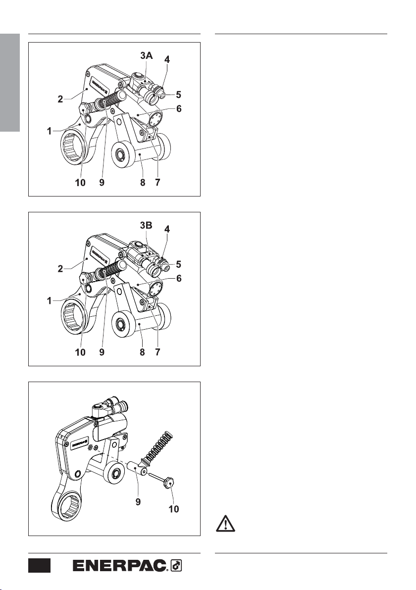
3.1 Overview and features (fig. A or B)
1 Spanner
2 Roller Cassette
3A Swivel
3B TSP-Pro Swivel
4 Advance hose connection
5 Return hose connection
6 Hydraulic drive unit
7 Cassette release lever
8 Reaction roller bracket and rollers
9 Positioning handle
10 Thumb screw
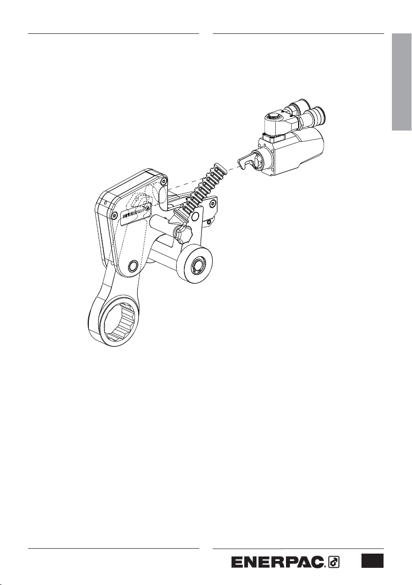
3.2.1 To attach the positioning handle
• Secure the positioning handle (9) with
Note: handle can be installed on
3.2.2 To remove the cassette (fig. D)
• Make sure the piston is fully retracted.
• Hold the tool with the drive unit
• Swing the
• Pull the release lever (7) outwards.
• Remove the cassette (2) from the
manifold (standard)
manifold (optional)
(fig. C)
thumb screw (10). Tighten hand tight.
either side of wrench (as needed).
pointing upwards.
reaction roller bracket (8)
inward, toward center of tool.
hydraulic drive unit (6).
Fig. C
6
3.2.3 To attach the cassette (fig. D and E)
• Make sure the retract link (11) aligns
with the slot (12) in the spanner (1).
Rotate the piston rod if necessary.
• Pull the release lever (7) outwards.
• Push the spigot (13) through the hole
in the cylinder locating plate (14).
• Push the release lever (7) back into
the cassette (2). Make sure the ball
detent clicks into place.
Do not operate the tool if the cassette
release lever is not fully closed.

Fig. D
Fig. E
• Swing the reaction roller bracket (8)
outward, away from center of tool.
3.3 To connect the hoses (fig. F)
Make sure all accessories meet the
pressure requirements.
Make sure the quick connect
couplings are securely attached
before operating the tool.
The tool is fitted with male and female
quick-connect couplings. Use Enerpac
twin safety hoses only. Refer to the table
below:
Hose model number Description
THQ-706T
THQ-712T
Two hoses, length
6 m (19.5 feet)
Two hoses, length
12 m (39 feet)
• Remove the hose dust caps.
• Connect the hose with the female
coupling (15) to the advance
coupling (4).
• Pull the sleeve on the female coupling
of the hose over the advance
coupling.
• Tighten the sleeve.
• Connect the hose with the male
coupling (16) into the return
coupling (5).
• Pull the sleeve on the return coupling
over the male coupling of the hose.
• Tighten the sleeve.
• Connect the hoses to the pump.
Refer to the pump instruction manual.
ENGLISH
Fig. F
7

ENGLISH
Fig. G
Fig. H
Fig. I
4 Operation
4.1 Prior to operation
- Make sure the nut or bolt to be
fastened is clean and free of dust.
- Make sure the nut or bolt runs
correctly on the thread.
- Make sure that the threads and the
bearing surface are liberally coated
with the correct lubricant or antiseizure compound.
- Make sure that the spanner used to
keep the nut or bolt on the opposite
end in place, is of the correct size
and that there is an adequate
abutment surface.
4.2 To set the torque
Adjust the pressure on the pump as
necessary to set the torque. Refer to sections
6.3.1 and 6.3.2 for torque setting tables.
4.3.1 To tighten a nut or bolt (fig. G, H, I)
• Place the wrench on the ground or on
a solid surface, such as a workbench.
• Operate the pump in the Retract
direction until drive unit is fully
retracted and the spanner socket
moves fully outward. Stop the pump.
• Swing the reaction roller bracket fully
outward, away from center of tool.
• Position the tool on the nut (bolt) with
the clockwise (+) side facing upwards.
• Position reaction roller against pipe
flange. Note: If a gap between
roller and flange is present, position
the roller as close to the flange as
possible, so that gap is minimal.
• Operate the pump in the Advance
direction to activate the wrench and
begin tightening the nut (bolt).
Stop operation immediately if a gap
appears between the cylinder
locating plate and the drive unit.
Never strike the tool with a hammer.
8

PINCH POINT
HAZARD
Keep hands and fingers clear of pinch
point area between spanner and
reaction roller. See Fig J.
Keep hands and fingers clear of pinch
point area between pipe flange and
reaction roller. See Fig J.
• Repeat previous steps as required
until nut (bolt) is tightened to the
proper torque.
Notes:
Spanner must be repositioned
after each wrench cycle by operating
the pump in the Retract direction. The
tool contains no spring return.
ENGLISH
Fig. J
Fig. K
4.3.2 To loosen a nut or bolt (fig. K, L)
• Apply penetrating oil to the threads.
Allow the oil to soak.
•
Reinstall the positioning handle on
counter-clockwise (-) side of wrench.
• To loosen the nut (bolt), follow steps
in section 4.3.1, but with the counterclockwise (-) side of wrench facing
upward.
• Repeat steps until nut (bolt) is loose.
If the nut or bolt will be re-used avoid
excess load when loosening.
- Be aware that when loosening a nut
or bolt more torque is usually required
than when tightening.
- Humidity corrosion (rust) requires
up to twice the torque required for
tightening.
- Sea water and chemical corrosion
requires up to two and a half times
the torque required for tightening.
- Heat corrosion requires up to
three times the torque required for
tightening.
Fig. L
Be aware that when loosening a nut
or bolt shock loading can occur. Do
not apply more than 75% of the
wrench’s maximum torque when
loosening nuts or bolts.
9

ENGLISH
Fig. M
Fig. N
5 Maintenance and troubleshooting
5.1 Spanner replacement (Fig M)
• Remove drive unit from cassette.
• Loosen and remove
• Tap
spanner pin (18) on one end and
remove it from the cassette.
• Slide spanner (1) out of cassette
housing.
• Apply a thin coat of molybdenum
disulphide lubricant
of the new spanner and to the
pin
at top of spanner.
• Slide new spanner (1) into cassette
housing. Align hole in spanner with
mating holes in sideplates.
• Install
spanner pin (18) through holes.
Before installation, be sure that flat
area of pin is aligned with
hole in spanner.
• Apply a small amount of Loctite 243
to threads of
• Reinstall
set screw (17).
5.2 Preventative maintenance (Fig N & O)
Preventative maintenance can be
carried out by the user. Full
maintenance must be carried out by
an approved and authorized
technician appointed by Enerpac.
Recommended service intervals are:
a) 3 months – Heavy Duty use
b) 6 months – Normal use
c) 12 months – Infrequent use
set screw (17).
to the sides
spring
set screw
set screw (17).
Fig. O
10
- Non destructive testing must be
carried out if the tool has been used
under severe conditions.
5.2.1 The roller cassette
• Remove drive unit from cassette.
• Remove
the shoulder screws (20). Lift
and remove the sideplate (21).
• Remove spanner (1),
and
set screw (17) as an assembly.
• Remove
reaction roller bracket pin
spanner pin (18)
(22) and reaction roller bracket (23).

• Remove circlips (24) reaction rollers
(25) and
roller pin (26).
• Clean all exposed components with a
mild solvent.
• Inspect all parts for damage.
• Dry all components. Apply a thin coat
of molybdenum disulphide lubricant
as indicated.
ENGLISH
5.2.2 The hydraulic drive unit
• Check tightness of swivel
manifold
post retaining screws (see 5.3.2) and
gland.
• Pressurize the drive unit to maximum
pressure (Advance and Retract), and
check for any signs of leakage.
• Any damaged components or seals
must be replaced.
• Dry all components and apply a
thin coat of molybdenum disulphide
lubricant
as indicated.
5.3 Full maintenance
Note: Refer to the WCR4000 repair
parts sheet for detailed views of
components and subassemblies
referenced in sections 5.3.1 and 5.3.2.
5.3.1 The roller cassette
• Strip down and clean all exposed
components with a mild solvent.
• Drift out the
cylinder retaining pin, and remove
retaining pin
spring pin holding the
the
.
• Inspect all parts for damage.
•
Perform non destructive testing by
magnetic particle inspection on the
following components:
-
Sideplates
- Cylinder locating plate
- Cylinder retaining pin
- Reaction roller bracket and pin
- Reaction rollers and roller pin
• Dry all components. Apply a thin coat
of molybdenum disulphide lubricant
as indicated.
Retaining Pin Height - Dimension “X”
Metric Imperial
5,00 mm 0.197 inch
Fail Safe Pin Height - Dimension “Y”
Metric Imperial
3,00 mm 0.118 inch
Fig. P
• Check retaining pin height (X) and fail
safe pin height (Y). Refer to Fig.P.
• Reverse the procedure to reassemble
the tool.
5.3.2 The hydraulic drive unit
• Remove the circlip from the
swivel
manifold block.
• Remove the hydraulic couplings.
• Remove the
swivel manifold block
from the drive unit.
• Remove
swivel manifold post
the retaining screws and the
.
• Remove all ‘O’ rings from swivel
manifold post.
• Carefully hold the cylinder body to
unscrew the cylinder gland.
• Hold the two flat sides of the piston
rod with a spanner. The rod is located
at the spigot.
• Remove the button head cap screw
from the piston.
• Remove the piston rod from the
cylinder spigot end.
• Remove the piston from the cylinder
gland end, using a suitable drift.
11

• Clean all exposed components with a
• Reverse the procedure to reassemble.
mild solvent.
• Inspect all parts for damage.
•
Perform non destructive testing by
magnetic particle inspection on the
ENGLISH
following components:
- Cylinder
body
- Piston rod
• Apply a small amount of Loctite 243
to the threads of the
capscrew
before reassembly.
button head
When reassembling the drive unit make
sure that the piston rod is inserted
through the cylinder spigot end.
When reassembling the drive unit
make sure that the piston is inserted
through the gland end. Tap the piston
gently into place against the piston
rod.
• Apply a small amount of Loctite
243 to the threads in the drive unit,
assemble the swivel
manifold post
and tighten the degreased retaining
screws to 5,1 Nm
(3.76 Ft.lbs).
• Pressurize the assembled drive unit to
max pressure (Advance and Retract),
and check for any signs of leakage.
5.4 Troubleshooting
5.4.1 Drive Unit
Symptom Cause Remedy
Cylinder does not advance or retract. Quick-connect coupling Replace the coupling.
is damaged.
Quick connect coupling is Reconnect the hoses
not connected. and couplings securely.
Dirt in the direction control Disassemble the unit and
valve on the pumping unit. clean the valve.
Cylinder does not build pressure. Piston seal leaks. Replace the seals.
Pump does not build pressure. Adjust the pressure.
Pump is defective. Refer to the pump manual.
Cylinder leaks. Seal failure. Replace the cylinder seals.
Cylinder operates backwards. Connections are reversed.
Reconnect hoses correctly.
5.4.2 Cassette
Symptom Cause Remedy
Drive unit operates Spanner broken Replace the spanner.
but spanner does not move. or damaged. Note: Top of spanner
contains fail-safe area
that is designed to
break in event of overload.
Spanner operation Fasteners loose. Check tightness of all
rough or erratic. screws and other fasteners.
Parts bent, worn Disassemble and inspect
or damaged. roller cassette. Clean,
lubricate and replace
parts as needed.
12

A
ENGLISH
Fig. Q
C
B
D
E
6 Technical specifications and torque settings
6.1 Capacities and dimensions - Model WCR4000
(fig. Q)
Spanner size range mm 36 - 80
inch 1
Maximum operating pressure bar 690
psi 10,000
Max. torque at 690 bar Nm 5.762
at 10,000 psi Ft.lbs 4,250
Min. torque Nm 576
Ft.lbs 425
Dimensions A mm (inch) 226 (8.9)
B mm (inch) 161 (6.3)
C mm (inch) 159 (6.25)
D mm (inch) 241 (9.5)
E mm (inch) 131 (5.2)
Weight (cassette only) kg (lbs) 6,2 (13.6)
(drive unit only) kg (lbs) 4,0 (8.8)
(drive unit and cassette) kg (lbs) 10,2 (22.5)
Note: Refer to section 6.2 for spanner weights and dimensions.
7
/16 - 3 1/8
13

6.2 Technical Data - Closed End Spanners
(fig. R)
6.2.1 Metric system table
ENGLISH
Spanner (F) (G) (H) Weight
Model
mm mm mm kg
W4107CS 36 31,0 30,0 1,9
W4108CS
W4110CS
W4113CS
W4114CS
W4200CS
W4203CS
W4206CS
W4209CS
W4212CS
W4215CS
W4302CS
38 32,8 30,0 2,1
41 32,8 30,0 2,2
46 35,6 30,0 2,1
48 38,4 30,0 2,1
50 38,4 30,0 2,2
55 41,2 30,0 2,1
60 45,0 30,0 2,2
65 46,8 30,0 2,1
70 49,6 30,0 2,2
75 52,1 30,0 2,1
80 55,4 30,0 2,2
6.2.2 Imperial system table
Spanner (F) (G) (H) Weight
Model
inch inch inch lbs
W4107CS 1 7/16 1.22 1.18 4.0
W4108CS 1 1/2 1.26 1.18 4.7
W4110CS 1 5/8 1.26 1.18 4.7
W4113CS 1 13/16 1.38 1.18 4.6
W4114CS 1 7/8 1.50 1.18 4.6
W4200CS 2 1.50 1.18 4.8
W4203CS 2 3/16 1.61 1.18 4.5
W4206CS 2 3/8 1.81 1.18 4.9
W4209CS 2 9/16 1.81 1.18 4.5
W4212CS 2 3/4 1.93 1.18 4.9
W4215CS 2 15/16 2.05 1.18 4.5
W4302CS 3 1/8 2.17 1.18 4.9
G
Fig. R
F
H
14

6.3 Torque settings
To set the torque, adjust the pump pressure
according to the following calculation:
Pump pressure = Torque / Torque factor
Measurement system Torque factor
Metric 8,351
Imperial 0.425
ENGLISH
6.3.1 Metric system pressure/torque
table - Model
WCR4000
Pump pressure (bar) Torque (Nm)
69 576
124 1.036
179 1.495
207 1.729
234 1.954
262 2.188
290 2.422
317 2.647
345 2.881
372 3.107
400 3.340
428 3.574
455 3.800
483 4.034
510 4.259
538 4.493
566 4.727
593 4.952
621 5.186
648 5.411
690 5.762
6.3.2 Imperial system pressure/torque
table - Model WCR4000
Pump pressure (psi) Torque (Ft.lbs)
1,000 425
1,800 765
2,600 1,105
3,000 1,275
3,400 1,445
3,800 1,615
4,200 1,785
4,600 1,955
5,000 2,125
5,400 2,295
5,800 2,465
6,200 2,635
6,600 2,805
7,000 2,975
7,400 3,145
7,800 3,315
8,200 3,485
8,600 3,655
9,000 3,825
9,400 3,995
10,000 4,250
15

7 Replacement parts and
recommended tools
7.2 Recommended
maintenance and repairs
tools for performing
7.1 To order replacement parts
ENGLISH
For replacement parts information,
refer to the Enerpac repair parts
sheet for your wrench model. Repair
parts sheets are available on the
internet at www.enerpac.com.
Have the following information ready
when ordering replacement parts:
- Wrench model and serial numbers
(for both drive unit and cassette).
- Approximate date of purchase.
- Part number and description of each
part being ordered.
– 1 7/8" A/F spanner
– 1 3/4" A/F spanner
– 1 5/8" A/F spanner
– 1 Circlip pliers
– 1 Seal extraction tool
– 1 ø 4 mm x 5 mm LG x 25 mm PCD
pin spanner
– 1 6 mm A/F Allen key
– 1 4 mm A/F Allen key
– 1 3 mm A/F Allen key
– 1 2,5 mm A/F Allen key
– 1 Copper hammer
– 1 3 mm terminal screwdriver
Notes:
A/F = Across Flats
PCD = Pitch Circle Diameter
16

NOTES:
17

NOTES:
18

NOTES:
19

Australia and New Zealand
Actuant Australia Ltd.
Block V Unit 3
Regents Park Estate
391 Park Road
Regents Park NSW 2143
(P.O. Box 261) Australia
T +61 (0)2 9743 8988
F +61 (0)2 9743 8648
sales-au@enerpac.com
Brazil
Power Packer do Brasil Ltda.
Rua
Luiz Lawrie Reid, 548
09930-760
- Diadema (SP)
T +55 11 5687 2211
F +55 11 5686 5583
Toll Free: 0800 891 5770
vendasbrasil@enerpac.com
Canada
Actuant Canada Corporation
6615 Ordan Drive, Unit 14-15
Mississauga, Ontario L5T 1X2
T +1 905 564 5749
F +1 905 564 0305
Toll Free:
T +1 800 268 4987
F +1 800 461 2456
customer.service@actuant.com
China
Actuant (China) Industries Co. Ltd.
No. 6 Nanjing East Road,
Taicang Economic Dep Zone
Jiangsu, China
T +86 0512 5328 7500
F +86 0512 5335 9690
Toll Free: +86 400 885 0369
sales-cn@enerpac.com
France, Switzerland, North Africa and
French speaking African countries
ENERPAC
Une division d’ACTUANT France S.A.
ZA de Courtaboeuf
32, avenue de la Baltique
91140 VILLEBON /YVETTE
France
T +33 1 60 13 68 68
F +33 1 69 20 37 50
sales-fr@enerpac.com
Germany and Austria
ENERPAC GmbH
P.O. Box 300113
D-40401 Düsseldorf
Willstätterstrasse 13
D-40549 Düsseldorf, Germany
T +49 211 471 490
F +49 211 471 49 28
sales-de@enerpac.com
India
ENERPAC Hydraulics Pvt. Ltd.
No. 1A, Peenya Industrial Area
IInd Phase, Bangalore, 560 058, India
T +91 80 40 792 777
F +91 80 40 792 792
sales-in@enerpac.com
Italy
ENERPAC S.p.A.
Via Canova 4
20094 Corsico (Milano)
T +39 02 4861 111
F +39 02 4860 1288
sales-it@enerpac.com
Japan
Applied Power Japan LTD KK
Besshocho 85-7
Kita-ku, Saitama-shi 331-0821, Japan
T +81 48 662 4911
F +81 48 662 4955
sales-jp@enerpac.com
Middle East, Egypt and Libya
ENERPAC Middle East FZE
Oce 423, LOB 15
P.O. Box 18004, Jebel Ali, Dubai
United Arab Emirates
T +971 (0)4 8872686
F +971 (0)4 8872687
sales-ua@enerpac.com
Russia
Rep. oce Enerpac
Russian Federation
Admirala Makarova Street 8
125212 Moscow, Russia
T +7 495
98090 91
F +7 495 98090 92
sales-ru@enerpac.com
and Taiwan
Actuant Asia Pte Ltd.
83 Joo Koon Circle
Singapore 629109
T +65 68 63 0611
F +65 64 84 5669
Toll Free: +1800 363 7722
sales-sg@enerpac.com
South Korea
Actuant Korea Ltd.
3Ba 717, Shihwa Industrial Complex
Jungwang-Dong, Shihung-Shi,
Kyunggi-Do
Republic of Korea 429-450
T +82 31 434 4506
F +82 31 434 4507
sales-kr@enerpac.com
Spain and Portugal
ENERPAC SPAIN, S.L.
Avda. Los Frailes, 40 – Nave C & D
Pol. Ind. Los Frailes
28814 Daganzo de Arriba
(Madrid) Spain
T +34 91 884 86 06
F +34 91 884 86 11
sales-es@enerpac.com
Sweden, Denmark, Norway, Finland
and Iceland
Enerpac Scandinavia AB
Fabriksgatan 7
412 50 Gothenburg
Sweden
T +46 (0) 31 799 0281
F +46 (0) 31 799 0010
scandinavianinquiries@enerpac.com
The Netherlands, Belgium,
Luxembourg,
Central and Eastern Europe,
Baltic States, Greece, Turkey
and CIS countries
ENERPAC B.V.
Galvanistraat 115
6716 AE Ede
P.O. Box 8097
6710 AB Ede
The Netherlands
T +31 318 535 911
F +31 318 535 848
sales-nl@enerpac.com
Enerpac Integrated Solutions B.V.
Opaalstraat 44
7554 TS Hengelo
P.O. Box 421
7550 AK Hengelo
The Netherlands
T +31 74 242 20 45
F +31 74 243 03 38
integratedsolutions@enerpac.com
South Africa and other English
speaking African countries
Enerpac Africa Pty Ltd.
No. 5 Bauhinia Avenue
Cambridge Oce Park
Block E
Highveld Techno Park
Centurion 0157
South Africa
T: +27 12 940 0656
United Kingdom and Ireland
ENERPAC Ltd.,
Bentley Road South
Darlaston, West Midlands
WS10 8LQ
England
T +44 (0)121 50 50 787
F +44 (0)121 50 50 799
sales-uk@enerpac.com
USA, Latin America and Caribbean
ENERPAC
P.O. Box 3241
Milwaukee WI 53201 USA
T +1 262 293 1600
F +1 262 293 7036
User inquiries:
T +1 800 433 2766
Distributor inquiries/orders:
T +1 800 558 0530
F +1 800 628 0490
Technical inquiries:
techservices@enerpac.com
sales-us@enerpac.com
All Enerpac products are guaranteed against
defects in workmanship and materials for as
long as you own them.
For the location of your nearest authorized
Enerpac Service Center, visit us at
www.enerpac.com
Enerpac Worldwide Locations e-mail: info@enerpac.com internet: www.enerpac.com
012313
Southeast Asia, Hong Kong
© Enerpac 09-2013 - All contents subject to change without notice.
 Loading...