

Page 1
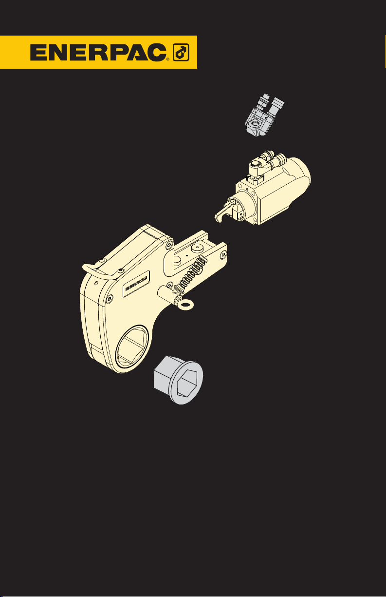
Instruction Sheet
W22000 Series
W35000 Series
Hydraulic Torque Wrench
L3009
English (GB) Rev. C 12/2011
Page 2

2
Page 3
Instruction Sheet Torque Wrench
W22000 Series
W35000 Series
Index
1 Introduction . . . . . . . . . . . . . . . . . . . . . . . . . . . . . . . . . . . . . . . . . . . . . . 4
2 Safety . . . . . . . . . . . . . . . . . . . . . . . . . . . . . . . . . . . . . . . . . . . . . . . . . . .4
3 Assembly and adjustments . . . . . . . . . . . . . . . . . . . . . . . . . . . . . . . . . . 6
4 Operation . . . . . . . . . . . . . . . . . . . . . . . . . . . . . . . . . . . . . . . . . . . . . . . . 8
5 Maintenance and troubleshooting . . . . . . . . . . . . . . . . . . . . . . . . . . . 10
6 Technical specifications - W22000 Series . . . . . . . . . . . . . . . . . . . . . 13
7 Technical specifications - W35000 Series . . . . . . . . . . . . . . . . . . . . . 19
8 Replacement parts and recommended tools . . . . . . . . . . . . . . . . . . 24
3
Page 4
1 Introduction
Overview
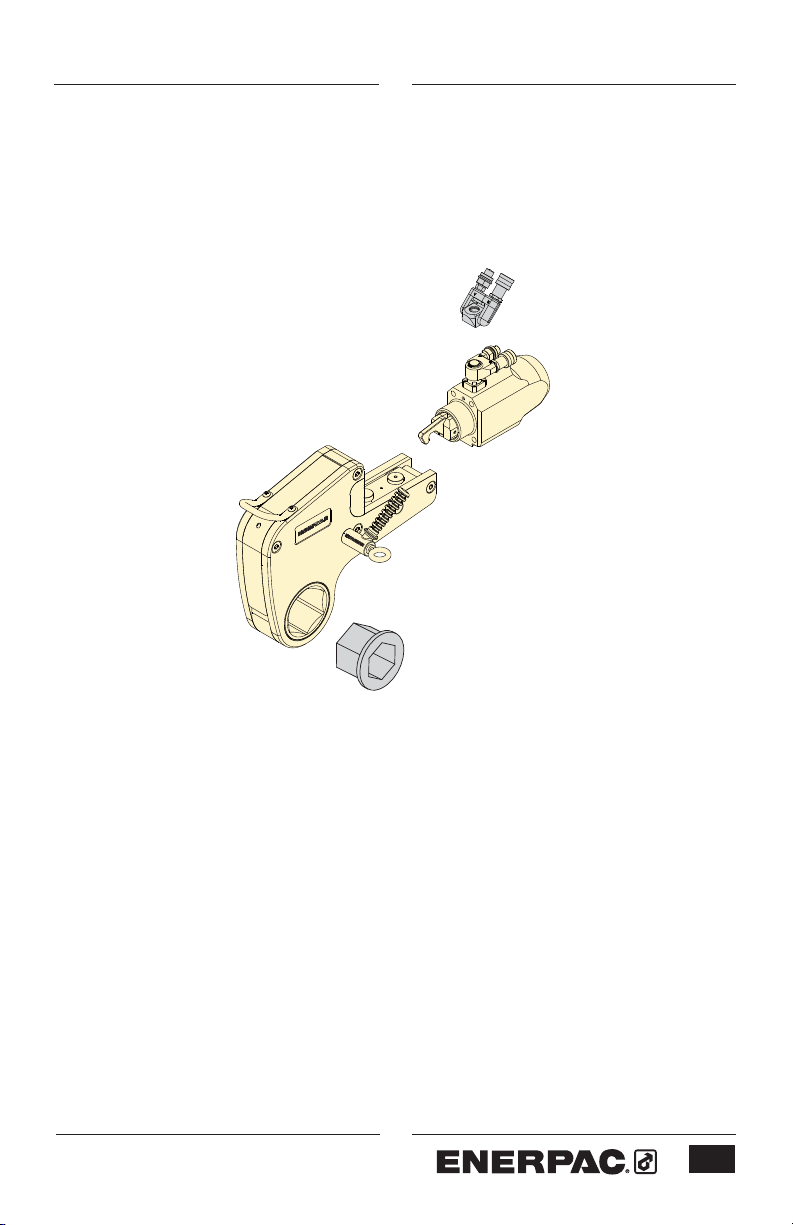
The Enerpac W-Series hydraulic torque
wrench is designed for controlled
tightening and loosening of fasteners
in industrial bolting applications. Its
low profile cassette, compact drive
unit and
the W-Series ideal for use in locations
where workspace is limited.
Interchangeable W-Series cassettes
are available in a large assortment of
both metric and imperial sizes to suit
specific customer requirements.
An optional TSP-Pro Series Swivel
provides 360 degree X-axis and 160
degree Y-axis rotation, allowing easier
positioning of the wrench and hoses in
confined areas.
The W-Series can be used with a
wide range of Enerpac bolting pumps.
Electric, air and hand style models are
available.
Delivery instructions
Upon delivery all components must be
inspected for damage incurred during
shipping. If damage is found the carrier
should be notified at once. Shipping
damage is not covered by the Enerpac
warranty.
Warranty
• Enerpac guarantees the product only
• All Enerpac products are guaranteed
Any misuse or alteration invalidates the
warranty.
• Observe all instructions as
• Replace any parts with Enerpac
integrated reaction foot make
for the purpose for which is intended.
against defects in workmanship and
materials for as long as you own
them.
communicated in this manual.
spare parts only.
CE Declaration of conformity
Enerpac declares that the W22000 and
W35000 Series torque wrenches meet
the applicable standards and directives
issued by the European Community.
For a detailed list refer to the separate
certification sheet.
2 Safety
Be aware that the operator is fully
responsible during the operation of
this tool. Enerpac is not responsible for
damage or injury caused by misuse of
this tool. Under some circumstances,
additional safety precautions beyond
those described in this manual may be
required. Contact Enerpac immediately
if a potentially hazardous situation
arises.
Read this manual carefully and
observe all safety precautions.
- Make sure you have completed safety
induction training, specific to the work
surroundings. The operator should be
thoroughly familiar with the controls
and the proper use of the tool.
- The operator must be at least
18 years of age.
- Always wear protective headwear, ear
protectors, footwear and gloves (at a
minimum rigger type gloves) suitable
for safe operation of the tool.
The protective clothing must not
interfere with safe operation of
the tool or restrict the ability to
communicate with co-workers.
- Make sure your workplace is safe.
- Do not place any part of the body
between the reaction foot and the
reaction point.
- Do not place any objects between
the reaction foot and the reaction
point. Keep the hoses away from the
reaction points.
- Do not stand in the line of movement
4
Page 5

of the tool when it is in operation. If
the tool separates from the nut or bolt
during operation it will detach in that
direction.
- Tightening and loosening nuts and
bolts involves little visible movement.
The pressure and loads, however
are extreme. Keep your hands away
from the fastener being loosened or
tightened.
- Make sure that the spanner used to
keep the nut or bolt on the opposite
end is secured.
- Always use Enerpac pumps and
hoses.
- Make sure appropriate guards are
always securely in position and free
from damage.
- Maximum pressure is 690 bar (10,000
psi). Never apply more pressure
to any tool or accessory than the
maximum allowable pressure. Refer
to the technical data tables for
maximum pressure setting.
- Make sure that the ratchet size
corresponds to the size of the
fastener being loosened or tightened.
Failure to do so can result in the tool
becoming unstable and can lead to
catastrophic failure of the tool.
- Do not abuse or overstress the hoses
in any way. Do not bend the hoses
excessively.
- Never carry the tool by its hoses.
- Always use Enerpac spare parts.
- Always position the tool for maximum
stability. Make sure reaction points
are adequate for the forces at work
during operation of the tool.
- Be aware that a nut or bolt that
breaks off during operation of the tool
will become a high velocity projectile.
- Make sure the reaction point is of
a suitable shape. For example use
an adjacent nut or bolt as a reaction
point.
- When the hex ratchet is placed on the
nut or bolt a gap may exist between
the reaction foot and the reaction
plate. When the tool is operated the
reaction foot and point will make
forceful contact. Always make sure
the tool is stable.
- Provide adequate support in vertical
and inverted applications.
- The maximum torque output of the
tool must always exceed the torque
required to loosen or tighten the nut
or bolt.
- The torque required to loosen a nut is
variable and may exceed the torque
capacity of the tool. Never operate
the tool at above 75 percent of tool
maximum torque when loosening a
nut or bolt (see section 4.3.2).
- Never operate the tool with a
hydraulic supply connection to
the advance side only as this may
damage the internal parts.
- If the wrench is dropped from a
height, have the tool inspected before
you operate it again.
- In severe conditions the tool must
be cleaned and lubricated more
frequently (see section 5).
- Check that the swivel post screws
(see 5.2.1) and gland are tight prior to
use.
- If oil leakage is evident, replace seals
accordingly (see section 5).
- Stop operation immediately if a gap
appears between the cylinder locating
plate and the drive unit. Have the tool
inspected and serviced before you
operate it again.
- Make sure to minimize torsional and
bending stresses in the tool, the hex
ratchet and any accessories.
- Do not strike the tool with a hammer
while under a full load. This will
invalidate the product warranty.
- Always observe the maintenance
instructions.
5
Page 6
3 Assembly and adjustments
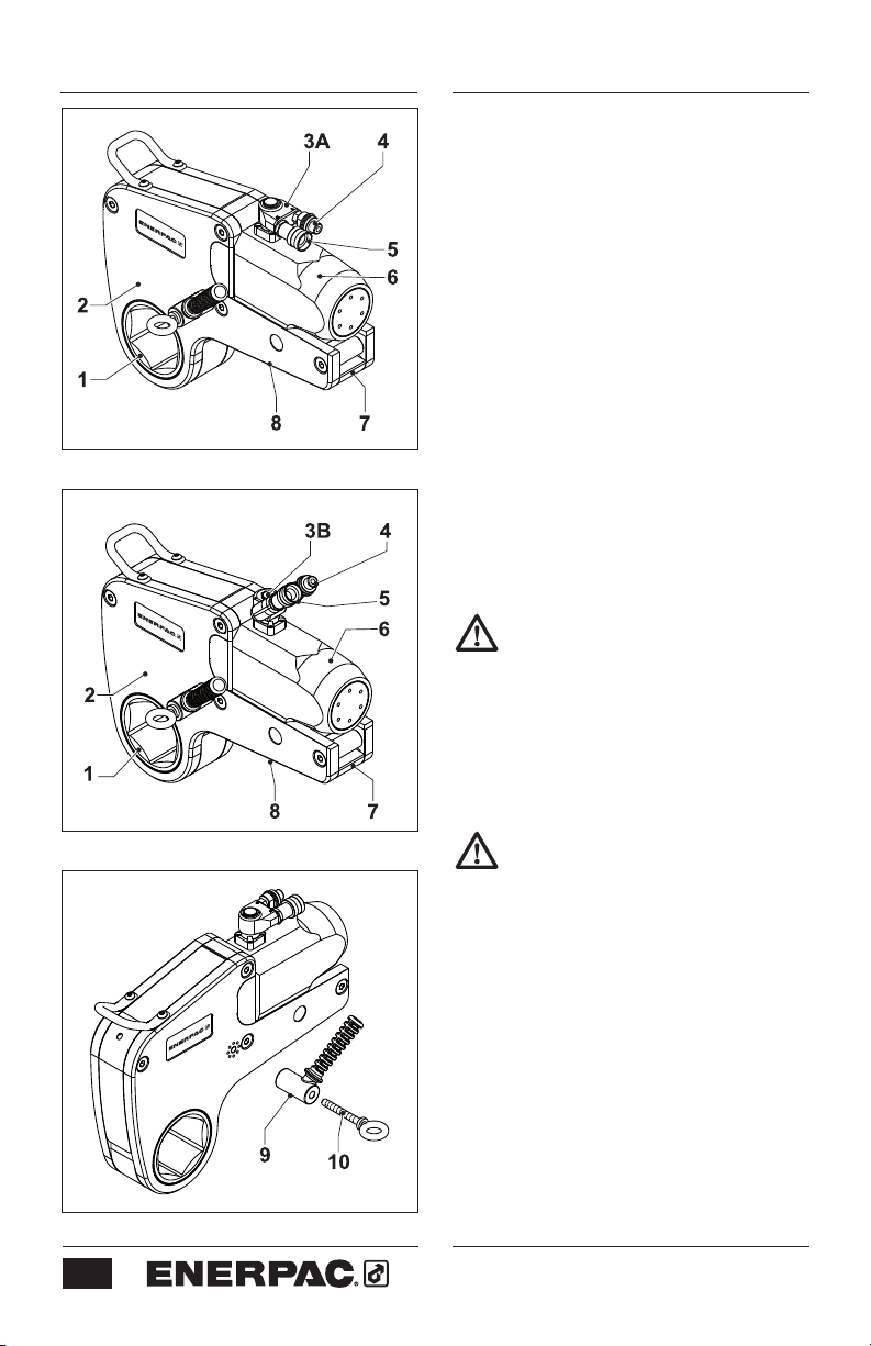
3.1 Overview and features
(fig. A or B)
1 Hexagon ratchet
2 Cassette
3A Swivel coupling or
3B TSP-Pro swivel coupling (optional)
4 Advance hose connection
5 Return hose connection
6 Hydraulic drive unit
7 Cassette release lever
8 Reaction foot
Fig. A
Fig. B
Fig. C
3.2 To attach the positioning handle
(fig. C)
• Secure the positioning handle (9) with
eye-bolt (10). Tighten hand tight.
3.3 Changing the cassette
Make sure to depressurize and
disconnect the tool from the
hydraulic supply first.
3.3.1 To remove cassette (fig. D & E)
• Make sure the piston is fully
retracted.
• Place the tool on a workbench or
support it using a hoist.
Hydraulic drive unit will disengage
from cassette in the following
steps. Be sure that cassette is
supported so it does not drop.
• Pull the cassette release lever (7)
outwards.
• Remove the hydraulic drive unit (6)
from the cassette (2).
3.3.2 To attach cassette (fig. D & E)
• Make sure the retract link (11) aligns
with the slot (13) in the crank. Rotate
the piston rod if necessary.
• Pull the release lever (7) outwards.
• Push the spigot (12) into the cylinder
locating plate (14).
6
Page 7
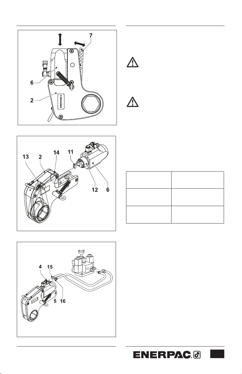
Fig. D
• Push the release lever (7) back into
the cassette (2). Make sure the ball
detent clicks into place.
Do not operate the tool if the
cassette release lever is not fully
closed.
3.4 To connect the hoses (fig. F)
Make sure all accessories meet
the pressure requirements.
Make sure the quick connect
couplings are securely attached
before operating the tool.
The tool is fitted with male and female
quick-connect couplings. Use Enerpac
twin safety hoses only. Refer to the
table below:
Fig. E
Fig. F
Enerpac hose
model number
THQ-706T
THQ-712T
Description
Two hoses, 6 m
(19.5 feet) long
Two hoses, 12 m
(39 feet) long
• Remove the hose dust caps.
• Connect the hose with the female
coupling (15) to the advance
coupling (4).
• Pull the sleeve on the female
coupling of the hose over the
advance coupling.
• Tighten the sleeve.
• Connect the hose with the male
coupling (16) into the return
coupling (5).
• Pull the sleeve on the return coupling
over the male coupling of the hose.
• Tighten the sleeve.
• Fit the hoses to the pump.
Refer to the pump instruction
manual.
7
Page 8
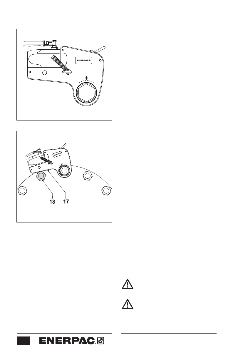
Fig. G
Fig. H
4 Operation
4.1 Prior to operation
- Make sure the nut or bolt to be
fastened is clean and free of dust.
- Make sure the nut or bolt runs
correctly on the thread.
- Make sure that the threads and the
bearing surface are liberally coated
with the correct lubricant or antiseizure compound.
- Make sure that the spanner used to
keep the nut or bolt on the opposite
end in place, is of the correct size
and that there is an adequate
abutment surface. Ensure that the
spanner is secured.
- Contact Enerpac if a suitable
reaction point is not available.
4.2 To set the torque
Adjust the pressure on the pump as
necessary to set the torque.
4.3.1 To tighten a nut or bolt
(fig. G & H)
• Position the tool on the nut or bolt
with the clockwise (+) side facing
upwards.
• Position the reaction foot (17) against
a suitable reaction point (18). The
reaction point will counteract the
force caused by operating the tool.
• Start the pump.
• Operate the pump until the nut or bolt
has been tightened to the required
torque.
• Stop the pump immediately after
work has finished.
Stop operation immediately if a
gap appears between the cylinder
locating plate and the drive unit.
Do not strike the tool with a
hammer while under a full load.
8
Page 9
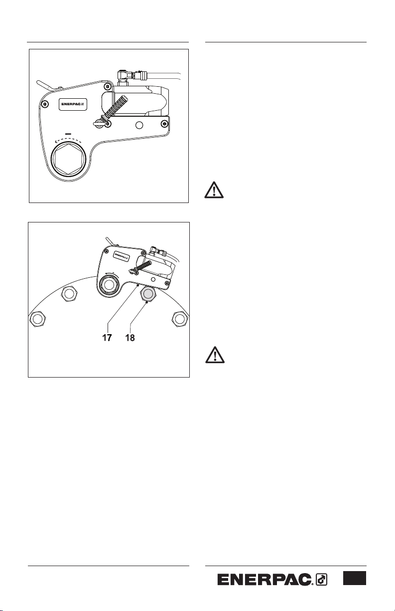
Fig. I
Fig. J
4.3.2 To loosen a nut or bolt (fig. I & J)
• Apply penetrating oil to the threads.
Allow the oil to soak.
• Position the tool on the nut or bolt
with the anti-clockwise (-) side facing
upwards.
• Position the reaction foot (17) against
a suitable reaction point (18). The
reaction point will counteract the
force caused by operating the tool.
• Start the pump.
• Operate pump until nut (bolt) is loose.
If the nut or bolt will be re-used
avoid excess load when
loosening.
- Be aware that when loosening a nut
or bolt more torque is usually required
than when tightening.
- Humidity corrosion (rust) requires
up to twice the torque required for
tightening.
- Sea water and chemical corrosion
requires up to two and a half times
the torque required for tightening.
- Heat corrosion requires up to
three times the torque required for
tightening.
Be aware that when loosening a
nut or bolt shock loading can
occur. Do not apply more than
75% of the wrench’s maximum
torque when loosening nuts or
bolts.
9
Page 10

5 Maintenance and troubleshooting
Preventative maintenance can be
carried out by the user. Full
maintenance must be carried out
by an approved and authorized
technician appointed by Enerpac.
Recommended service intervals
are:
a) 3 months – Heavy Duty use
b) 6 months – Normal use
c) 12 months – Infrequent use
- Non destructive testing must be
carried out if the tool has been used
under severe conditions.
Fig. K
5.1 Preventative maintenance
(fig. K & L)
5.1.1 The hydraulic drive unit
• Check tightness of swivel post
retaining screws (see 5.2.1) and
gland.
• Pressurize the drive unit to maximum
pressure (Advance and Retract), and
check for any signs of leakage.
• Any damaged components or seals
must be replaced.
• Dry all components and apply a thin
coat of molybdenum disulphide as
indicated (19).
Molybdenum disulphide is
available from Enerpac.
5.1.2 The cassette
• Remove the cassette from the drive
unit.
• Remove the screws (20). Lift and
remove the sideplates (21).
• Remove the hex ratchet (22),
spring loaded drive shoe (23), and
compression springs (24).
• Clean all exposed components with a
mild solvent.
• Inspect all parts for damage.
• Dry all components. Apply a thin
coat of molybdenum disulphide as
indicated (19).
Fig. L
10
Do not apply any lubricant to the
ratchet or drive shoe teeth.
Page 11

5.2 Full maintenance
5.2.1 The hydraulic drive unit
• Remove the circlip from the swivel
coupling.
• Remove the couplings.
• Remove the swivel-coupling block
from the drive unit.
• Remove the swivel post by removing
the swivel post retaining screws.
• Remove all ‘O’ rings from the swivel
post.
• Carefully hold the cylinder body to
unscrew the cylinder gland.
• Hold the two flat sides of the piston
rod with a spanner. The rod is located
at the spigot.
• Remove the button head cap screw
from the piston.
• Remove the piston rod from the
cylinder spigot end.
• Remove the piston from the cylinder
gland end, using a suitable drift.
• Clean all exposed components with a
mild solvent.
• Inspect all parts for damage.
• Carry out non destructive testing by
magnetic particle inspection on the
following components:
- Cylinder
- Piston rod
• Apply a small amount of Loctite 243
to the threads of the piston retaining
screw before reassembly.
• Apply a small amount of Loctite 243
to the threaded holes in the drive unit.
Assemble the swivel post and tighten
the degreased swivel post retaining
screws (M5 screws) to 10,2 Nm.
• Reverse the procedure to reassemble
• Pressurize the assembled drive
unit to max pressure (Advance and
Retract), and check for any signs of
leakage.
When reassembling the drive unit
make sure that the piston rod is
inserted through the cylinder
spigot end.
When reassembling the drive unit
make sure that the piston is
inserted through the gland end.
Tap the piston gently into place
against the piston rod.
5.2.2 The cassette
• Strip down and clean all exposed
components with a mild solvent.
• Drift out the roll pin holding the
cylinder retaining pin, and remove.
• Inspect all parts for damage.
• Carry out non destructive testing by
magnetic particle inspection on the
following components:
- Sideplates
- Locating plate
- Pin retainer
- Reaction foot
- Crank
- Ratchet
- Drive shoe
- Cylinder retaining pin
- Spacer retaining pin
• Dry all components. Apply a thin
coat of molybdenum disulphide as
indicated (19).
11
Page 12

• As a check, refer to figure M and the
tables below for the correct height of
the drive unit retaining pin (Y).
Pin Height - W22000 Series
(fig. M, dimension “Y”)
Metric Imperial
7,5 mm 0.296 inch
Pin Height - W35000 Series
(fig. M, dimension “Y”)
Metric Imperial
Fig. M
7,0 mm 0.276 inch
• Reverse the procedure to reassemble
the tool.
5.3 Troubleshooting
5.3.1 Drive Unit
Symptom Cause Remedy
Cylinder does not advance Quick-connect coupling Replace the coupling
or retract is damaged
Quick-connect coupling is Reconnect the hoses
not connected and couplings securely
Dirt in the direction control Disassemble the unit
valve on the pumping unit and clean the valve
Cylinder does not build up Piston seal leaks Replace the seals
pressure Pump does not build pressure Adjust the pressure
Pump is defective Refer to the pump manual
Cylinder leaks Seal failure Replace the cylinder seals
Cylinder operates backwards Connections are reversed Reconnect the hoses
5.3.2 Cassette
Symptom Cause Remedy
Ratchet returns on retract stroke Broken drive shoe Replace the drive shoe
Ratchet does not take Defective drive shoe Replace the drive shoe
successive strokes
Lubricant on the ratchet Disassemble the
and/or drive shoe splines cassette and remove the
lubricant from splines
12
Page 13

L
B
A
M
D
S
F
H
K
G
N
E
I
C
Fig. N
6 Technical specifications - W22000 Series
6.1 W22000 Series - Capacities and dimensions (fig. N)
Cassette capacity * mm 75 - 135
inch 2
Maximum operating pressure bar 690
psi 10,000
Max. torque at 690 bar Nm 30.506
at 10,000 psi Ft.lbs 22,500
Min. torque Nm 3.051
Ft.lbs 2,250
Dimensions A mm (inch) 227,2 (8.94)
B mm (inch) 265,7 (10.46)
C mm (inch) 296,6 (11.68)
D mm (inch) 77,0 (3.03)
E mm (inch) 48,0 (1.89)
F mm (inch) 35,0 (1.38)
G - - - (see Section 6.2)
H - - - (see Section 6.2)
I mm (inch) 60,3 (2.37)
K mm (inch) 98,0 (3.86)
L mm (inch) 74,4 (2.93)
M mm (inch) 107,0 (4.21)
N mm (inch) 127,6 (5.02)
S - - - (see Section 6.2)
Weight of Drive Unit kg (lbs) 7,7 (16.98)
15
/16 - 5 3/8
* Important: Hexagon reducer inserts (if used) must meet minimum wall thickness requirements. Refer
to Section 6.2 for additional information. Consult your Enerpac distributor regarding the availability of
inserts for your cassette model.
13
Page 14

6.2 Cassette capacities - W22000 Series
6.2.1 Metric system table
(See fig. N for dimensions S, G and H)
Cassette (S) (G) (H) Weight
Model mm mm mm kg
W22215 75 102 67,0 22,1
W22300 77 102 67,0 22,0
W22301 78 102 67,0 21,9
W22302 80 102 67,0 21,7
W22303 81 107,5 72,5 22,9
W22304 83 107,5 72,5 22,8
W22305 84 107,5 72,5 22,6
W22085M 85 107,5 72,5 22,6
W22306 86 107,5 72,5 22,5
W22308 89 107,5 72,5 22,2
W22090M 90 113 78 23,5
W22309 91 113 78 23,4
W22310 92
113 78 23,3
W22311 94 113 78 23,1
W22312 95 113 78 23,1
W22313 97 113 78 22,8
W22314 99 113 78 22,6
W22315 100 120 85 24,3
W22400 102 120 85 24,1
W22402 105 120 85 23,8
W22404 108
120 85 23,4
W22405 110 125 90 24,6
W22406 111 125 90 24,5
W22407 113 125 90 24,3
W22115M 115 125 90 24,1
W22412 120 130 95 24,7
W22123M 123
130 95 24,4
W22414 124 130 95 24,3
W22500 127 130 95 23,8
W22502 130 135 100 25,0
W22506 135 135 100 23,9
Cassette Model Required minimum wall thickness of hexagon reducer insert:
W22205 - W22404 9,2 mm
W22405 - W22506 7,75 mm
Important: If wall thickness is less than shown in the table above, the insert may experience reduced
component life.
14
Consult your Enerpac distributor regarding the availability of inserts for your cassette model.
Page 15

6.2.2 Imperial system table
Cassette (S)
Model inch
W22215 2
W22300 3
W22301 3
W22302 3
W22303 3
W22304 3
W22305 3
W22306 3
W22307 3
W22308 3
W22309 3
W22310 3
W22311 3
W22312 3
W22313 3
W22314 3
W22315 3
15
1
/16
1
/8
3
/16
1
/4
5
/16
3
/8
7
/16 4.23 2.85 50.3
1
/2
9
/16
5
/8
11
3
/4
13
7
/8 4.45 3.07 49.8
15
(See fig. N for dimensions S, G and H)
(G) (H) Weight
/16
inch inch lbs
4.02 2.64 48.7
4.02 2.64 48.4
4.02 2.64 48.2
4.02 2.64 47.8
4.23 2.85 50.6
4.23 2.85 50.2
4.23 2.85 49.9
4.23 2.85 49.7
4.23 2.85 48.9
4.45 3.07 51.6
4.45 3.07 51.3
/16
4.45 3.07 50.9
4.45 3.07 50.6
/16
4.45 3.07 50.2
/16
4.72 3.35 53.6
W22400 4 4.72 3.35 53.2
W22401 4
W22402 4
W22403 4
W22404 4
W22405 4
W22406 4
W22407 4
W22408 4
W22409 4
W22410 4
W22412 4
W22414 4
1
/16
4.72 3.35 52.8
1
/8
4.72 3.35 52.4
3
/16
4.72 3.35 52.1
1
/4 4.72 3.35 51.5
5
/16
4.92 3.54 54.3
3
/8
4.92 3.54 53.9
7
/8
4.92 3.54 53.5
1
/2
4.92 3.54 53.1
9
/16
4.92 3.54 52.6
5
/8
4.92 3.54 52.0
3
/4
5.12 3.74 54.5
7
/8 5.12 3.74 53.6
W22500 5 5.12 3.74 52.4
W22502 5
W22503 5
W22504 5
W22506 5
1
/8
5.31 3.94 55.1
3
/16
5.31 3.94 54.7
1
/4
5.31 3.94 54.1
3
/8
5.31 3.94 52.8
Cassette Model Required minimum wall thickness of hexagon reducer insert:
W22205 - W22404 0.36 inch
W22405 - W22506 0.31 inch
Important: If wall thickness is less than shown in the table above, the insert may experience reduced
component life.
Consult your Enerpac distributor regarding the availability of inserts for your cassette model.
15
Page 16

6.3 Torque settings - W22000 Series
6.3.1 Metric system pressure/torque table - W22000 Series
Pump pressure (bar) Torque (Nm)
69 3.051
83 3.670
97 3.670
110 4.864
124 5.483
138 6.102
152 6.721
166 7.340
179 7.915
193 8.534
207 9.153
221 9.772
234 10.347
248 10.966
262 11.585
276 12.204
290 12.823
303 13.398
317 14.017
331 14.636
345 15.255
359 15.874
372 16.449
Pump pressure (bar) Torque (Nm)
386 17,068
400 17,687
414 18,306
428 18,925
441 19,500
455 20,119
469 20,738
483 21,357
497 21,976
510 22,551
524 23,170
538 23,789
552 24,408
566 25,027
579 25,602
593 26,221
607 26,840
621 27,459
634 28,034
648 28,653
662 29,272
676 29,891
690 30,510
16
To set the torque, adjust the pump pressure according to
the following calculation:
Pump pressure = Desired Torque ÷ Torque Factor
Torque Factor (metric system)
W22000 Series
44,217
Page 17

6.3.2 Imperial system pressure/torque table - W22000 Series
Pump pressure (psi) Torque (Ft.lbs)
1,000 2,250
1,200 2,700
1,400 3,150
1,600 3,600
1,800 4,050
2,000 4,500
2,200 4,950
2,400 5,400
2,600 5,850
2,800 6,300
3,000 6,750
3,200 7,200
3,400 7,650
3,600 8,100
3,800 8,550
4,000 9,000
4,200 9,450
4,400 9,900
4,600 10,350
4,800 10,800
5,000 11,250
5,200 11,700
5,400 12,150
Pump pressure (psi) Torque (Ft.lbs)
5,600 12,600
5,800 13,050
6,000 13,500
6,200 13,950
6,400 14,400
6,600 14,850
6,800 15,300
7,000 15,750
7,200 16,200
7,400 16,650
7,600 17,100
7,800 17,550
8,000 18,000
8,200 18,450
8,400 18,900
8,600 19,350
8,800 19,800
9,000 20,250
9,200 20,700
9,400 21,150
9,600 21,600
9,800 22,050
10,000 22,500
To set the torque, adjust the pump pressure according to
the following calculation:
Pump pressure = Desired torque ÷ Torque Factor
Torque Factor (imperial system)
W22000 Series
2.25
17
Page 18

NOTES:
18
Page 19

/
%
Fig. O
$
0
'
6
+
.
*
1
,
)
&
(
7 Technical specifications - W35000 Series
7.1 W35000 Series - Capacities and dimensions (fig. O)
Cassette capacity * mm 80 - 155
inch 3
Maximum operating pressure bar 690
psi 10,000
Max. torque at 690 bar Nm 47.453
at 10,000 psi Ft.lbs 35,000
Min. torque Nm 4.745
Ft.lbs 3,500
Dimensions A mm (inch) 268 (10.54)
B mm (inch) 303 (11.94)
C mm (inch) 345 (13.60)
D mm (inch) 91 (3.57)
E - - - (see Section 7.2)
F mm (inch) 50 (1.98)
G - - - (see Section 7.2)
H - - - (see Section 7.2)
I mm (inch) 79,5 (3.13)
K mm (inch) 108 (4.2)
L mm (inch) 74,4 (2.93)
M mm (inch) 107 (4.21)
N mm (inch) 127 (5.00)
S - - - (see Section 7.2)
Weight of Drive Unit kg (lbs) 12 (26.4)
* Important: Hexagon reducer inserts (if used) must meet minimum wall thickness requirements. Refer
to Section 7.2 for additional information. Consult your Enerpac distributor regarding the availability of
inserts for your cassette model.
1
/8 - 6 1/8
19
Page 20

7.2 Cassette capacities - W35000 Series
7.2.1 Metric system table
(See fig. O for dimensions S, E, G and H)
Cassette (S) (E) (G) (H) Weight
Model mm mm mm mm kg
W35302 80 73,0 126,75 76,0 32,8
W35303 81 73,0
126,75 76,0 32,7
W35304 83 73,0 126,75 76,0 32,5
W35305 84 73,0 126,75 76,0 32,4
W35085M 85 73,0 126,75 76,0 32,3
W35306 86 73,0 126,75 76,0 32,2
W35308 89 73,0
126,75 76,0 32,0
W35090M 90 72,4 132,5 81,5 33,5
W35309 91 72,4 132,5 81,5 33,4
W35310 92 72,4 132,5 81,5 33,3
W35311 94 72,4 132,5 81,5 33,1
W35312 95 72,4 132,5 81,5 32,9
W35313 97
72,4
132,5 81,5 32,7
W35314 99 72,4 132,5 81,5 32,4
W35315 100 71,9 137,0 87,0 34,1
W35400 102 71,9 137,0 87,0 33,9
W35402 105 71,9 137,0 87,0 33,5
W35404 108 71,9 137,0 87,0 33,0
W35405 110 71,3 143,0 93,0 34,9
W35406 111 71,3 143,0 93,0 34,7
W35407 113 71,3 143,0 93,0 34,5
W35115M 115
71,3
143,0 93,0 34,2
W35412 120 70,7 148,5 98,5 35,6
W35123M 123 70,7 148,5 98,5 35,0
W35414 124 70,7 148,5 98,5 34,9
W35500 127 70,7 148,5 98,5 34,3
W35502 130 70,2 153,0 103,0 35,8
W35506 135
70,2
153,0 103,0 34,6
W35508 140 69,6 158,5 108,5 36,2
W35509 141 69,6 158,5 108,5 36,0
W35510 143 69,6 158,5 108,5 35,6
W35512 145 69,6 158,5 108,5 34,9
W35514 150 69,1 164,0 114,0 36,7
W35151M 151 69,1 164,0 114,0 36,5
W35600 153 69,1 164,0 114,0 36,1
W35602 155 69,1 164,0 114,0 35,3
Cassette Model Required minimum wall thickness of hexagon reducer insert:
W35302 - 35404 14,50 mm
W35405 - 35602 12,00 mm
Important: If wall thickness is less than shown in the table above, the insert may experience reduced
component life.
20
Consult your Enerpac distributor regarding the availability of inserts for your cassette model.
Page 21

7.2.2 Imperial system table
(See fig. O for dimensions S, E, G and H)
Cassette (S) (E) (G) (H) Weight
Model inch inch inch inch lbs
W35302 3
W35303 3
W35304 3
W35305 3
W35306 3
W35307 3
W35308 3
W35309 3
W35310 3
W35311 3
W35312 3
W35313 3
W35314 3
W35315 3
1
/8
3
/16
1
/4
5
/16
2.87 4.99 2.99 71.4
3
/8
7
/16
2.87 4.99 2.99 70.5
1
/2
2.87 4.99 2.99 70.1
9
/16
2.85 5.22 3.21 71.4
5
/8
2.85 5.22 3.21 73.4
11
/16
2.85 5.22 3.21 73.0
3
/4
2.85 5.22 3.21 72.5
13
/16
2.85 5.22 3.21 72.1
7
/8
2.85 5.22 3.21 71.4
15
/16
2.83 5.39 3.42 70.8
2.87 4.99 2.99 72.3
2.87
2.87
2.87
4.99 2.99 72.1
4.99 2.99 71.7
4.99 2.99 71.0
W35400 4 2.83 5.39 3.42 74.7
W35401 4
W35402 4
W35403 4
W35404 4
W35405 4
W35406 4
W35407 4
W35408 4
W35409 4
W35410 4
W35412 4
W35414 4
1
/16 2.83 5.39 3.42 74.3
1
/8
2.83 5.39 3.42 73.9
3
/16
1
/4
2.83 5.39 3.42 72.8
5
/16
2.81 5.63 3.66 76.9
3
/8
2.81 5.63 3.66 76.5
7
/16 2.81 5.63 3.66 76.1
1
/2
2.81 5.63 3.66 75.6
9
/16
2.81 5.63 3.66 75.2
5
/8
2.81 5.63 3.66 74.5
3
/4
2.78 5.85 3.88 78.5
7
/8
2.78 5.85 3.88 76.9
2.83
5.39 3.42 73.4
W35500 5 2.78 5.85 3.88 75.6
W35502 5
W35503 5
W35504 5
W35506 5
W35508 5
W35509 5
W35510 5
W35512 5
W35514 5
1
/8
2.76 6.02 4.05 78.9
3
/16 2.76 6.02 4.05 78.5
1
/4
2.76 6.02 4.05 77.6
3
/8
1
/2
2.74 6.24 4.27 79.8
9
/16
2.74 6.24 4.27 79.4
5
/8
2.74 6.24 4.27 78.5
3
/4
2.74 6.24 4.27 76.9
7
/8
2.72 6.46 4.49 80.9
2.76
6.02 4.05 76.3
W35600 6 2.72 6.46 4.49 79.6
W35602 6
Cassette Model Required minimum wall thickness of hexagon reducer insert:
W35302 - 35404 0.57 inch
W35405 - 35602 0.48 inch
Important: If wall thickness is less than shown in the table above, the insert may experience reduced
component life.
1
/8
2.72 6.46 4.49 77.8
Consult your Enerpac distributor regarding the availability of inserts for your cassette model.
21
Page 22

7.3 Torque settings - W35000 Series
7.3.1 Metric system pressure/torque table - W35000 Series
Pump pressure (bar) Torque (Nm)
69 4.745
83 5.708
97 6.671
110 7.565
124 8.528
138 9.491
152 10.453
166 11.416
179 12.310
193 13.273
207 14.236
221 15.199
234 16.093
248 17.055
262 18.018
276 18.981
290 19.944
303 20.838
317 21.801
331 22.764
345 23.726
359 24.689
372 25.583
Pump pressure (bar) Torque (Nm)
386 26.546
400 27.509
414 28.472
428 29.434
441 30.328
455 31.291
469 32.254
483 33.217
497 34.180
510 35.074
524 36.037
538 36.999
552 37.962
566 38.925
579 39.819
593 40.782
607 41.745
621 42.707
634 43.601
648 44.564
662 45.527
676 46.490
690 47.453
22
To set the torque, adjust the pump pressure according to
the following calculation:
Pump pressure = Desired Torque ÷ Torque Factor
Torque Factor (metric system)
W35000 Series
68.772
Page 23

7.3.2 Imperial system pressure/torque table - W35000 Series
Pump pressure (psi) Torque (Ft.lbs)
1,000 3,500
1,200 4,200
1,400 4,900
1,600 5,600
1,800 6,300
2,000 7,000
2,200 7,700
2,400 8,400
2,600 9,100
2,800 9,800
3,000 10,500
3,200 11,200
3,400 11,900
3,600 12,600
3,800 13,300
4,000 14,000
4,200 14,700
4,400 15,400
4,600 16,100
4,800 16,800
5,000 17,500
5,200 18,200
5,400 18,900
Pump pressure (psi) Torque (Ft.lbs)
5,600 19,600
5,800 20,300
6,000 21,000
6,200 21,700
6,400 22,400
6,600 23,100
6,800 23,800
7,000 24,500
7,200 25,200
7,400 25,900
7,600 26,600
7,800 27,300
8,000 28,000
8,200 28,700
8,400 29,400
8,600 30,100
8,800 30,800
9,000 31,500
9,200 32,200
9,400 32,900
9,600 33,600
9,800 34,300
10,000 35,000
To set the torque, adjust the pump pressure according to
the following calculation:
Pump pressure = Desired torque ÷ Torque Factor
Torque Factor (imperial system)
W35000 Series
3.5
23
Page 24

8 Replacement parts and
recommended tools
8.3 Recommended tool kit for
W35000 Series
8.1 To order replacement parts
For replacement parts
information, refer to the Enerpac
repair parts sheet for your wrench
model. Repair parts sheets are
available on the internet at
www.enerpac.com.
Have the following information
ready when ordering replacement
parts:
- Wrench model and serial
numbers (for both drive unit
and cassette).
- Approximate date of purchase.
- Part number and description of
each part being ordered.
8.2 Recommended tool kit for
W22000 Series
- 7/8" A/F spanner
- 3/4" A/F spanner
- 5/8" spanner
- Circlip pliers
- Seal extraction tool
- 1-11/16" A/F spanner
- ø 5 mm x 6 mm LG x 45 mm
PCD pin spanner
- 10 mm A/F Allen key
- 6 mm A/F Allen key
- 4 mm A/F Allen key
- 2,5 mm A/F Allen key
- 3 mm Terminal screwdriver
- 7/8" A/F spanner
- 3/4" A/F spanner
- 5/8" spanner
- Circlip pliers
- Seal extraction tool
- 2" A/F spanner
- ø 5 mm x 6 mm LG x 50 mm
PCD pin spanner
- 10 mm A/F Allen key
- 8 mm A/F Allen key
- 4 mm A/F Allen key
- 2,5 mm A/F Allen key
- 3 mm Terminal screwdriver
Notes:
A/F = Across Flats
PCD = Pitch Circle Diameter
Notes:
A/F = Across Flats
PCD = Pitch Circle Diameter
24
Page 25

NOTES:
25
Page 26

NOTES:
26
Page 27

NOTES:
27
Page 28

Enerpac Worldwide Locations e-mail: info@enerpac.com internet: www.enerpac.com
Australia and New Zealand
Actuant Australia Ltd.
Block V Unit 3
Regents Park Estate
391 Park Road
Regents Park NSW 2143
(P.O. Box 261) Australia
T +61 (0)2 9743 8988
F +61 (0)2 9743 8648
sales-au@enerpac.com
Brazil
Power Packer do Brasil Ltda.
Rua dos Inocentes, 587
04764-050 - Sao Paulo (SP)
T +55 11 5687 2211
F +55 11 5686 5583
Toll Free: 0800 891 5770
vendasbrasil@enerpac.com
Canada
Actuant Canada Corporation
6615 Ordan Drive, Unit 14-15
Mississauga, Ontario L5T 1X2
T +1 905 564 5749
F +1 905 564 0305
Toll Free:
T +1 800 268 4987
F +1 800 461 2456
customer.service@actuant.com
China
Actuant (China) Industries Co. Ltd.
No. 6 Nanjing East Road,
Taicang Economic Dep Zone
Jiangsu, China
T +86 0512 5328 7500
F +86 0512 5335 9690
Toll Free: +86 400 885 0369
sales-cn@enerpac.com
France, Switzerland, North Africa and
French speaking African countries
ENERPAC
Une division d’ACTUANT France S.A.
ZA de Courtaboeuf
32, avenue de la Baltique
91140 VILLEBON /YVETTE
France
T +33 1 60 13 68 68
F +33 1 69 20 37 50
sales-fr@enerpac.com
Germany and Austria
ENERPAC GmbH
P.O. Box 300113
D-40401 Düsseldorf
Willstätterstrasse 13
D-40549 Düsseldorf, Germany
T +49 211 471 490
F +49 211 471 49 28
sales-de@enerpac.com
India
ENERPAC Hydraulics Pvt. Ltd.
No. 1A, Peenya Industrial Area
IInd Phase, Bangalore, 560 058, India
T +91 80 40 792 777
F +91 80 40 792 792
sales-in@enerpac.com
Italy
ENERPAC S.p.A.
Via Canova 4
20094 Corsico (Milano)
T +39 02 4861 111
F +39 02 4860 1288
sales-it@enerpac.com
Japan
Applied Power Japan LTD KK
Besshocho 85-7
Kita-ku, Saitama-shi 331-0821, Japan
T +81 48 662 4911
F +81 48 662 4955
sales-jp@enerpac.com
Middle East, Egypt and Libya
ENERPAC Middle East FZE
Oce 423, LOB 15
P.O. Box 18004, Jebel Ali, Dubai
United Arab Emirates
T +971 (0)4 8872686
F +971 (0)4 8872687
sales-ua@enerpac.com
Russia
Rep. oce Enerpac
Russian Federation
Admirala Makarova Street 8
Moscow, Russia
125212
T +7 495 98090 91
F +7 495 98090 92
sales-ru@enerpac.com
Singapore
Actuant Asia Pte Ltd.
83 Joo Koon Circle
Singapore 629109
T +65 68 63 0611
F +65 64 84 5669
Toll Free: +1800 363 7722
sales-sg@enerpac.com
South Korea
Actuant Korea Ltd.
3Ba 717, Shihwa Industrial Complex
Jungwang-Dong, Shihung-Shi,
Kyunggi-Do
Republic of Korea 429-450
T +82 31 434 4506
F +82 31 434 4507
sales-kr@enerpac.com
Spain and Portugal
ENERPAC SPAIN, S.L.
Avda. Los Frailes, 40 – Nave C & D
Pol. Ind. Los Frailes
28814 Daganzo de Arriba
(Madrid) Spain
T +34 91 884 86 06
F +34 91 884 86 11
sales-es@enerpac.com
Sweden, Denmark, Norway, Finland
and Iceland
Enerpac Scandinavia AB
Fabriksgatan 7
412 50 Gothenburg
Sweden
T +46 (0) 31 799 0281
F +46 (0) 31 799 0010
scandinavianinquiries@enerpac.com
The Netherlands, Belgium,
Luxembourg,
Central and Eastern Europe,
Baltic States, Greece, Turkey
and CIS countries
ENERPAC B.V.
Galvanistraat 115
6716 AE Ede
P.O. Box 8097
6710 AB Ede
The Netherlands
T +31 318 535 911
F +31 318 535 848
sales-nl@enerpac.com
Enerpac Integrated Solutions B.V.
Opaalstraat 44
7554 TS Hengelo
P.O. Box 421
7550 AK Hengelo
The Netherlands
T +31 74 242 20 45
F +31 74 243 03 38
integratedsolutions@enerpac.com
South Africa and other English
speaking African countries
Enerpac Africa Pty Ltd.
No. 5 Bauhinia Avenue
Cambridge Oce Park
Block E
Highveld Techno Park
Centurion 0157
South Africa
T: +27 12 940 0656
United Kingdom and Ireland
ENERPAC Ltd.,
Bentley Road South
Darlaston, West Midlands
WS10 8LQ
England
T +44 (0)121 50 50 787
F +44 (0)121 50 50 799
sales-uk@enerpac.com
USA, Latin America and Caribbean
ENERPAC
P.O. Box 3241
Milwaukee WI 53201 USA
T +1 262 293 1600
F +1 262 293 7036
User inquiries:
T +1 800 433 2766
Distributor inquiries/orders:
T +1 800 558 0530
F +1 800 628 0490
Technical inquiries:
techservices@enerpac.com
sales-us@enerpac.com
All Enerpac products are guaranteed against
defects in workmanship and materials for as
long as you own them.
For the location of your nearest authorized
Enerpac Service Center, visit us at
www.enerpac.com
101711
© Enerpac 11-2011 - Subject to change without notice.
 Loading...