

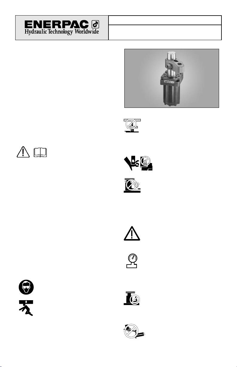
Page 1
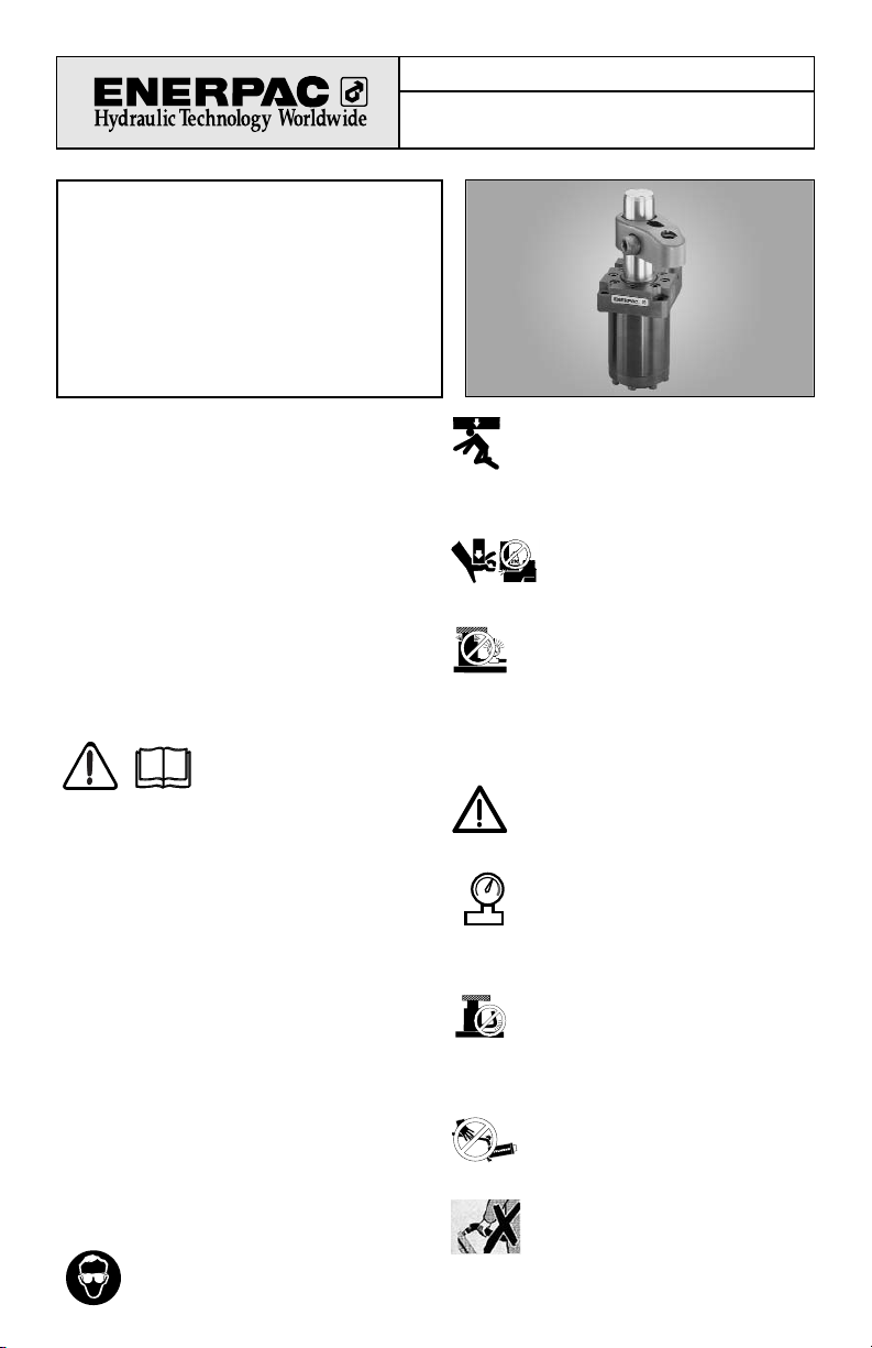
Instruction Sheet
Swing Cylinders – Metric
9,0 kN, 18,8 kN and 35 kN
Index:
English...............................................................1-8
Français.......................................................... 9-16
Deutsch........................................................ 17-24
Italiano.......................................................... 25-32
Español ........................................................ 33-40
Nederlands................................................... 41-48
®
L2063 Rev D 09/02
Repair Parts Sheets for this product are available
from the Enerpac web site at www.enerpac.com, or
from your nearest Authorized Enerpac Service Center
or Enerpac Sales office.
1.0 IMPORTANT RECEIVING
INSTRUCTIONS
Visually inspect all components for shipping damage.
Shipping damage is not covered by warranty. If
shipping damage is found, notify carrier at once. The
carrier is responsible for all repair and replacement
costs resulting from damage in shipment.
SAFETY FIRST
2.0 SAFETY ISSUES
Read all instructions,
warnings and cautions
carefully. Follow all safety
precautions to avoid personal injury or property
damage during system operation. Enerpac cannot be
responsible for damage or injury resulting from
unsafe product use, lack of maintenance or incorrect
product and/or system operation. Contact Enerpac
when in doubt as to the safety precautions and
operations. If you have never been trained on highpressure hydraulic safety, consult your distribution or
service center for a free Enerpac Hydraulic safety
course.
Failure to comply with the following cautions and
warnings could cause equipment damage and
personal injury.
A CAUTION is used to indicate correct operating or
maintenance procedures and practices to prevent
damage to, or destruction of equipment or other
property.
A WARNING indicates a potential danger that
requires correct procedures or practices to avoid
personal injury.
A DANGER is only used when your action or lack of
action may cause serious injury or even death.
WARNING: Wear proper personal
protective gear when operating hydraulic
equipment.
WARNING: Stay clear of loads
supported by hydraulics. A cylinder,
when used as a load lifting device, should
never be used as a load holding device. After the
load has been raised or lowered, it must always be
blocked mechanically.
DANGER: To avoid personal injury
keep hands and feet away from
cylinder and workpiece during
operation.
WARNING: Do not exceed equipment
ratings. Never attempt to lift a load
weighing more than the capacity of the
cylinder. Overloading causes equipment failure and
possible personal injury. The cylinders are designed
for a max. pressure of 350 bar [5,000 psi]. Do not
connect a jack or cylinder to a pump with a higher
pressure rating.
Never set the relief valve to a higher
pressure than the maximum rated pressure
of the pump. Higher settings may result in
equipment damage and/or personal injury.
WARNING: The system operating
pressure must not exceed the pressure
rating of the lowest rated component in
the system. Install pressure gauges in the
system to monitor operating pressure. It is your
window to what is happening in the system.
CAUTION: Avoid damaging hydraulic
hose. Avoid sharp bends and kinks when
routing hydraulic hoses. Using a bent or
kinked hose will cause severe back-pressure. Sharp
bends and kinks will internally damage the hose
leading to premature hose failure.
Do not drop heavy objects on hose. A
sharp impact may cause internal damage
to hose wire strands. Applying pressure to
a damaged hose may cause it to rupture.
IMPORTANT: Do not lift hydraulic
equipment by the hoses or swivel
couplers. Use the carrying handle or other
means of safe transport.
®
Page 2
Model Number Code
1 2 3 4 optional 5 6 optional
S = swing T = threaded body R = right swing S = single L = long 9 = 9,0 kN 2 = metric V = Viton
cylinder U = upper flange L = left swing acting stroke 2024 lb
L = lower flange S* = straight D = double 35 kN only 20 = 18,8 kN
(no swing) acting 3900 lb
35 = 35,0 kN
7600 lb
* Straight movement is not available on 35,0 kN (7600 lb) long stroke model.
CAUTION: Keep hydraulic equipment
away from flames and heat. Excessive
heat will soften packings and seals,
resulting in fluid leaks. Heat also weakens hose
materials and packings. For optimum performance
do not expose equipment to temperatures of 65 °C
[150 °F] or higher. Protect hoses and cylinders from
weld spatter.
DANGER: Do not handle pressurized
hoses. Escaping oil under pressure can
penetrate the skin, causing serious injury.
If oil is injected under the skin, see a doctor
immediately.
WARNING: Only use hydraulic cylinders in
a coupled system. Never use a cylinder
with unconnected couplers. If the cylinder
becomes extremely overloaded,
components can fail catastrophically causing severe
personal injury.
WARNING: BE SURE SETUP IS STABLE
BEFORE LIFTING LOAD. Cylinders
should be placed on a flat surface that can
support the load. Where applicable, use a
cylinder base for added stability. Do not
weld or otherwise modify the cylinder to attach a
base or other support.
Avoid situations where loads are not
directly centered on the cylinder plunger.
Off-center loads produce considerable
strain on cylinders and plungers. In addition, the load
may slip or fall, causing potentially dangerous results.
Distribute the load evenly across the entire
saddle surface. Always use a saddle to
protect the plunger.
IMPORTANT: Hydraulic equipment must
only be serviced by a qualified hydraulic
technician. For repair service, contact the
Authorized ENERPAC Service Center in
your area. To protect your warranty, use only
ENERPAC oil.
WARNING: Immediately replace worn or
damaged parts by genuine ENERPAC
parts. Standard grade parts will break
causing personal injury and property
damage. ENERPAC parts are designed to fit properly
and withstand high loads.
3.0 DESCRIPTION
These swing cylinders are designed to swing 90° in a
clockwise or counter-clockwise direction. They can
also be used in straight clamping applications.
Single-acting and double-acting swing cylinders are
available. Clamp arms are not supplied with
cylinders. Clamp arms can be purchased separately
or made according to the specifications on page 8.
2
®
Page 3
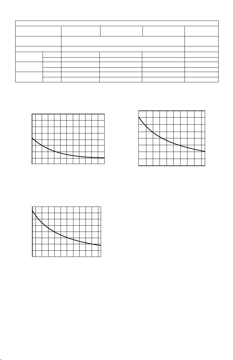
4.0 SPECIFICATIONS
4.1 Clamping Force -v- Arm Length Graphs
4.2 PRELIMINARY INFORMATION
IMPORTANT: Failure to read and follow these
instructions may lead to system malfunction or product
failure, and could invalidate your warranty.
1. High flow rates can lead to excessive cylinder
speed which can cause the kick-out mechanism to
activate. Hydraulic pressure and cylinder speed must
be adjusted to match the length of clamp arm. The
clamping force also varies with thelength of the clamp
arm.Refer to page 2 for operating specifications.
Refer to page 2 for operating specifications.
2. Flow controls with return checks should be used to
reduce swing cylinder speed to the recommended
rate. The return checks help minimize back pressure
that could lead to an unclamp malfunction on singleacting systems.
3. When using single-acting swing cylinders, limit the
return flow back pressure to 3,5 bar (50 psi)
maximum. Large diameter tubing (10 mm [3/8 in.]
O.D. or larger) and flow controls with free flow return
checks help minimize back pressure. Consult
Enerpac for proper system design.
4. Excessive return flow back pressure can also
activate the kick-out mechanism on double-acting
swing cylinders. Limit the return flow back pressure
to 42 bar (600 psi) maximum. Double-acting systems
should be set up for a metered-in with reverse free
flow in the clamp port.
5. Clamping of the part should occur at the midpoint of
the vertical travel. No clamping of part shall occur
while the swing clamp is turning. Clamp arm should
freely travel during the 90° rotation (avoid contact
with cutter heads, tools, etc.).
6. Attaching clamp arm to cylinder plunger must be
done according to the instructions on page 6.
3
Cylinder Specifications
Capacity kN (lbs) 9,0 kN (2024) 18,8 (3900) 35,0 (7600) 35,0 (7600)
Long Stroke
Body Style threaded body, lower flange, or upper flange mounting
upper flange
mounting
Cylinder Type single-acting and double-acting double-acting
Hydraulic clamp 12 (0.47) 14,0 (0.55) 16,0 (0.63) 31,8 (1.25)
Stroke [mm (in)] total 22 (0.87) 28,0 (1.10) 30,0 (1.18) 46,5 (1.83)
Effective Area clamp 3,13 (0.49) 7,16 (1.11) 12,42 (1.925) 12,42(1.925)
[cm2(in2)] unclamp 8,04 (1.25) 15,21 (2.356) 23,76 (3.683) 23,76(3.683)
Oil Capacity clamp 6,88 (0.42) 20,0 (1.22) 37,2 (2.27) 57,9 (3.53)
[cm3(in3)] unclamp 17,69 (1.08) 42,6 (2.60) 71,3 (4.35) 111,0 (6.77)
9,0 kN (2024 lb) Models
350 265 200 160 135 115 100
(5000) (3840) (2900) (2320) (1960) (1770) (1450)
12
(270)
10
(220)
8
(180)
6
(130)
4
(90)
Force kN (lbs.)
2
(45)
0
45 60 80 100 120 140 160
(1.77) (2.36) (3.15) (3.94) (4.73) (5.51) (6.30)
CAS-92 CAL-92Length mm (in. )
1,0 l/min . . . . . . . . . . . . . Q . . . . . . . . . . . . . . 0,6 l/min
(61 in3/min )
Pressure bar (psi)
(37 in3/min )
(5000) (2900) (2320) (1960) (1770) (1450)
35
(780)
30
(670)
30
(670)
25
(560)
20
(450)
Force kN (lbs.)
15
(340)
10
(220)
(110)
CAS-352 CAL-352Length mm (in.)
4,0 l/min . . . . . . . . . . . . . . . Q . . . . . . . . . . . . . . . . 2,0 l/min
(240 in
35,0 kN (7600 lb) Models
350 200 160 135 115 100
5
0
68 90 110 130 150 165
(2.68) (3.55) (4.33) (5.12) (5.90) (6.50)
3
/min )
Pressure bar (psi)
(120 in3/min)
18,8 kN (3900 lb) Models
350 250 215 175 150 130 120
(5000) (3630) (3120) (2540) (2200) (1890) (1740)
20,0
(450)
17,5
(390)
15,0
(340)
12,5
(280)
10,0
(220)
7,5
(170)
Force kN (lbs.)
5,0
(110)
2,5
(60)
0
55 70 90 110 130 150 165
(2.17) (2.76) (3.55) (4.33) (5.12) (5.90) (6.50)
CAS-202 CAL-202Length mm (in.)
2,5 l/min . . . . . . . . . . . . . Q . . . . . . . . . . . . . . 1,5 l/min
(150 in
Pressure bar (psi)
3
/min)
(92 in3/min)
Page 4
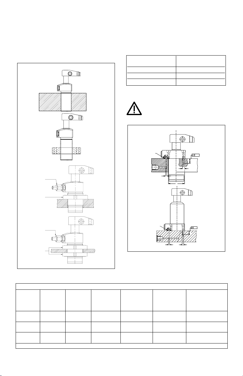
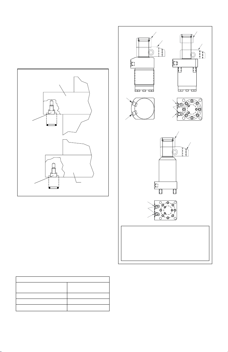
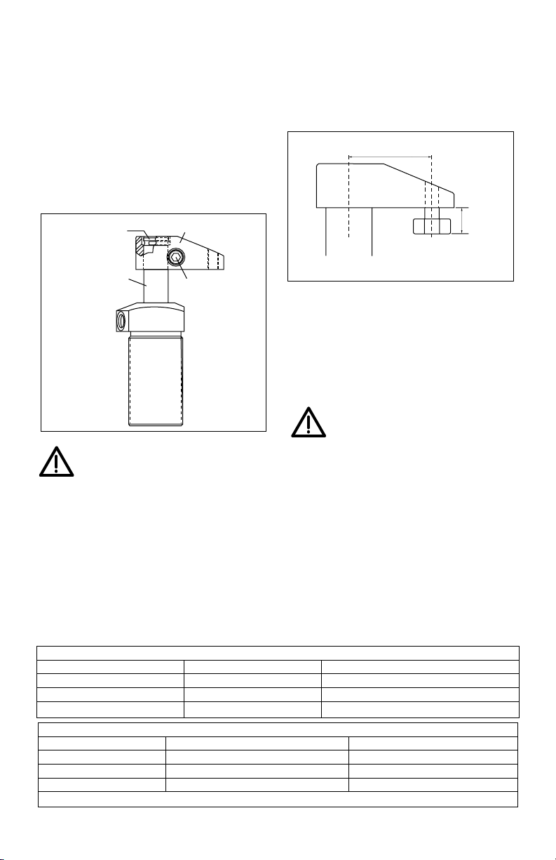
5.0 MOUNTING SPECIFICATIONS
5.1 Mounting Threaded Body Cylinders
Threaded body cylinders can be threaded into a tapped
hole, secured to the fixture using a mounting flange,
threaded into the fixture and secured with a jam nut, or
mounted through a clearance hole and secured with jam
nuts. See illustrations below.
When a threaded body style swing cylinder is being
installed in a fixture, the thread engagement should be
no less than the thread engagement for the standard
Enerpac mounting flange. If a cylinder is being mounted
using just the lower portion of the threads, the
engagement should be increased for additional support.
See table below for minimum thread engagement.
5..2 Mounting Upper and Lower Flange Cylinders
WARNING: The fixture must be capable of
withstanding 350 bar (5,000 psi) hydraulic
working pressure when the cylinders are
manifold mounted.
Cylinder Capacity Minimum Thread
Engagement
9,0 kN (2024 lb) 16 mm (0.63")
18,8 kN (3900 lb) 25 mm (1.00")
35,0 kN (7600 lb) 30 mm (1.25")
4
Manifold Specifications
Cylinder Max. Oil Fixture Mounting Minimum Lubricated Manifold
Capacity Channel Hole Threads Thread Mounting O-Ring
Diameter Diameter Depth Bolt Torque Dimensions
Ø A Ø B C D I.D. x w
9,0 kN 4mm 49,1± 0,8 M6x30 15 mm 13,5-15 Nm 4,34 x 3,56mm
2024 lb 0.156" 1.93± .03 0.59" 10-11 ft-lbs 0.171 x 0.139"
18,8 kN 0.156" 63,4± 0,4 M8x30 15 mm 32-38 Nm 4,34 x 3,56mm
3900 lb 4 mm 2.50 ± .02 0.59" 25-30 ft-lbs 0.171 x 0.139"
★ 35,0 kN 0.156" 77,5± 0,3 M10x30 15 mm 65-72 Nm 4,34 x 3,56mm
7600 lb 4mm 3.05 ± .01 0.59" 48-53 ft-lbs 0.171 x 0.139"
★ includes. long stroke
Threaded into
fixture
Mounting
flange
Oil connection
Jam nut
Jam nuts
Oil connection
Manifold
O-ring
Manifold
O-ring
0.003
0.003
A
B
C
D
A
C
D
Page 5
Before a swing cylinder can be manifold mounted, the
port screw plugs must be removed. The o-rings provided
should be lubricated and installed in the counter-bore
around the port prior to mounting and bolting down the
swing cylinder.
Be sure that the o-ring does not get pinched or damaged
during mounting as leakage could result. To prevent
leakage from the manifold mounting, provide a fixture
mounting surface with latness within 0,08 mm (0.003 in)
and a surface roughness not to exceed Ra 1,6
6.0 INSTALLATION
6.1 Hydraulic Connections
To make port connections, install fittings rated for 350
bar (5000 psi).
DO NOT use thread sealant. Sealing is accomplished by
using an o-ring on the fitting boss. Lubricate the o-ring
prior to assembly.
When designing your hydraulic circuit, consider the
factors listed in PRELIMINARY INFORMATION on page
3. For more information about plumbing hydraulic
circuits, see your Enerpac Production Automation
Catalog.
6.2 Port Identification
6.3 Vent Plug
Single-acting cylinders have a vented plug on the left
side of the cylinder when you are facing the hydraulic
ports. To prevent entry of chips and coolant, the vent
plug must not be removed. If the vent plug is subjected
to a continuous coolant flood condition, attach tubing to
the port using a BSPP fitting, and run the tubing to a noncontaminated area of the fixture.
Cylinder Ports
Cylinder Capacity 350 bar
BSPP Fitting
9,0 kN (2024 lb) G 1/4
18,8 kN (3900 lb) G 1/4
35,0 kN (7600 lb) G 1/4
5
KEY
A Port: Plunger rotates 90 ° and clamps
B Port: Double-acting -- Plunger unclamps and
rotates -90 °
Single-acting -- Vent Port
Do not remove vent plug except to attach tubing.
Upper flange
Remove port
screw plug
Remove port
screw plug
Lower flange
O-ring
O-ring
Unclamp
Clamp
Unclamp
Clamp
Upper flange
body style
(long stroke)
Side view
Side view
Bottom view
Bottom view
Manifold
ports
A
B
A
B
Unclamp
Clamp
Lower flange
body style
Manifold
ports
A
B
Bottom view
Threaded
Body
Side view
Threaded
Body
Page 6
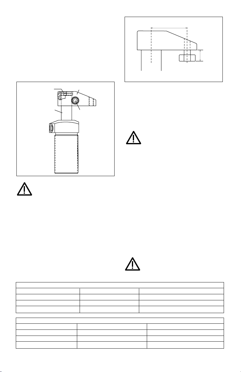
6.4 Attaching Clamp Arm
1. Remove the retaining ring from the top of the plunger.
2. Slide the clamp arm down over the plunger and use
a pliers to push the retaining ring back onto the
plunger groove. Orient the retaining ring so the
retaining ring gap will face the back of the clamp arm.
See illustration.
3. Move the clamp arm up until it is firmly against the
retaining ring and in the desired position. While
maintaining this position, torque the clamp arm bolt
to specification listed below.
CAUTION: Inadequate torquing of the
clamp arm bolt could cause the arm to slip
during operation. BE SURE TO USE QUALITY
12.9 DIN 912 (GRADE 8) SOCKET HEAD CAP SCREWS
(supplied with standard clamp arms).
6.5 Arms for Upper Flange Body Style
To use the upper flange body style cylinders, you have to
be sure that the contact bolt head will clear the upper
flange during operation. The clamp arm must be long
enough for the bolt head to clear the upper flange as the
arm swings down. Clearance problems are most
common when using the CAS series standard length
arm, with the final clamping position at the side of the
cylinder. You may need to use the longer CAL Series
clamp arm for these applications. You can cut CAL series
arms to meet your own requirements, or make your own
custom arms according to the dimensions on page 8.
7.0 OPERATION
Swing cylinders rotate 90° during the first portion of
the stroke, continuing without rotation for the final
clamping stroke. The straight downward stroke is the
clamping stroke of the cylinder. Clamping force must
be applied only during the vertical travel, not during
the swing motion.
CAUTION: — If clamping force is applied
during the rotation portion of the stroke,
internal plunger damage may result.
—To ensure maximum cylinder performance and
safety, be sure all hydraulic connections, hoses,
and fittings are properly sealed and fully
tightened.
—Be sure all items are rated to withstand system
pressures. Under-rated components will not
withstand higher pressure. Using under-rated
components will lead to equipment damage and
possible personal injury.
7.1 Turning Mechanism Protection
The kick-out turning mechanism protection is
designed to help prevent internal cylinder parts from
damage caused by obstructed plunger movement,
workpiece-clamp arm collision, and excessive oil
flow. If the kick-out mechanism activates, release
system pressure, check for the cause of the
activation and correct the problem. Return the
cylinder to its original position by hand or by using a
wrench.
CAUTION: After the kick-out mechanism
has been activated, always release the
hydraulic pressure in your system before
returning the mechanism to its original position.
6
Clamp Arm Bolt Torque
Cylinder Capacity Bolt Type Torque
9,0 kN (2024 lbs) M10 x 1.25 x 35 81-95 Nm (60-70 ft-lbs)
18,8 kN (3900 lbs) M12 x 1.25 x 40 95-108 Nm (70-80 ft-lbs)
35,0 kN (7600 lbs) M16 x 1.50 x 55 217-244 Nm (160-180 ft-lbs)
Maximum Contact Bolt Length
Cylinder Capacity Maximum Bolt Length CAS Series Arm
9,0 kN (2024 lbs) 18 mm (0.71”) L - 45 mm (1.77”)
18,8 kN (3900 lbs) 22 mm (0.875”) L - 55 mm (2.17”)
35,0 kN (7600 lbs) 24 mm (1.00”) L - 68 mm (2.68”)
Retaining ring
Clamping arm
(Opening toward
back of clamp arm)
Plunger
Clamp arm bolt
L
Contact bolt
(with head dia.
larger than 16mm [.63])
Max.
length
Page 7

7.2 Pressure and Flow Rate
Clamp arm length (L) determines operating pressure
setting and flow rate. See Clamping Force -v- Arm
Length Graphs on page 3 for clamp arm length, pressure
setting and flow rate. Set operating pressure and flow
rate according to the limits established by the length of
the clamp arm. Do not exceed the load-to-length
pressure ratios. As the arm length increases, the
clamping force and maximum operating pressure are
reduced.
CAUTION: It is very important that you use the
correct pressure and flow settings. Operating
outside these limits will cause damage to the
swing cylinder. Damage caused by exceeding rated
pressure and maximum flow is NOT COVERED BY
WARRANTY.
8.0 MAINTENANCE
Maintenance is required when wear or leakage is
noticed. Occasionally inspect all components to detect
any problem requiring service and maintenance.
Enerpac offers ready-to-use Repair Parts Kits. Repair
Parts Sheets are available with assembly drawing and
parts list. Contact Enerpac.
IMPORTANT: Consult the Repair Parts Sheet for service
information about correct assembly and disassembly.
Incorrect maintenance and service such as wrong torque
values may cause product malfunctions and/or personal
injury.
9.0 TROUBLESHOOTING
The following information is intended to be used only as
an aid in determining if a problem exists. For repair
service, contact your Distributor or Authorized Enerpac
Service Center.
7
Problem Possible Cause Solution
Cylinder will not clamp/unclamp. 1. Pump release valve open 1. Close pump release valve
2. No oil in pump reservoir 2. Fill pump reservoir
3. Air in system 3. Remove air from hydraulic system
4. Couplers not fully tightened 4. Retighten couplers
5. Blocked hydraulic line 5. Check valves, fittings, and tubing
6. Spring broken in cylinder 6. Replace spring
Cylinder advances part way. 1. Oil level in pump too low 1. Fill pump reservoir
2. Plunger binding 2. Replace damaged parts —refer to Repair
Parts Sheet
Kick-out mechanism activated. 1. Oil flow too high 1. Reduce oil flow
2. Workpiece-clamp arm collision 2. Prevent clamp arm collision—refer to
Turning Mechanism Protection on page 8
Cylinder clamps/unclamps 1. Leaking connection or loose fitting 1. Retighten fittings, couplers, and tubing
slower than normal. 2. Restricted hydraulic line 2. Check valves, fittings, and tubing
3. Pump malfunction 3. Refer to pump Instruction Sheet
Cylinder clamps/unclamps 1. Seals damaged 1. Replace seals — refer to Repair Parts Sheet
but will not hold pressure. 2. Leaking connection 2. Retighten fittings, couplers, and tubing
3. Pump malfunction 3. Refer to pump Instruction Sheet
Cylinder leaks oil. 1. Seals damaged 1. Replace seals—refer to Repair Parts Sheet
2. Plunger worn or damaged 2. Replace damaged parts—refer to Repair
Parts Sheet
Clamp arm does not make swing 1. Clamp arm loose 1. Reposition and tighten clamp arm—refer to
movement. Attaching Clamp Arm
2. Plunger damaged 2. Replace damaged parts
—refer to Repair Parts Sheet
L
Page 8
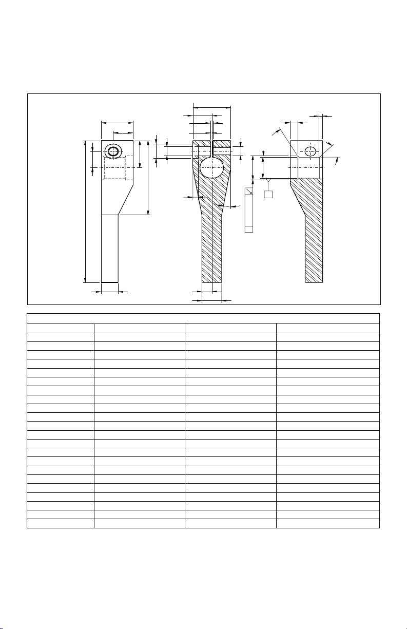
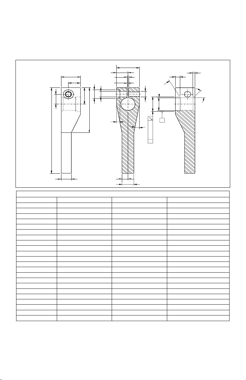
10.0 CLAMP ARM MACHINING
SPECIFICATIONS
Note: See Pressure and Flow Rate on page 7 to
correctly measure the arm length. To determine the
maximum clamping force for the arm, refer to
Clamping Force -v- Arm Length Graphs on page 3.
8
Dimensions are in mm (in.).
9,0 kN (2024 lb) 18,8 kN (3900 lb) 35,0 kN (7600 lb)
"A" 25 (0.99) 30 (1.18) 40(1.58)
"B" Max. 200 (7.88) 215 (8.47) 224 (8.83)
"C" 40 (1.58) 60 (2.36) 70 (2.76)
"D" 16 (0.63) 21 (0.83) 34 (1.34)
"E" 22 (0.87) 25 (0.99) 30 (1.18)
"F"(3 places) 86 (3.38) 107 (4.22) 114 (4.49)
"G" 30 (1.18) 35 (1.38) 40 (1.58)
"H" 12,5 (0.49) 15 (0.59) 20 (0.79)
"J" 20 (0.79) 30 (1.18) 35 (1.38)
"K" (Dia.) Ø 14 (0.55) Ø 17 (0.67) Ø 17 (0.67)
"L" 9 (0.35) 11 (0.43) 11 (0.43)
"M" (Dia.) Ø 9 (0.35) Ø 11 (0.43) Ø 11 (0.43)
"N" (Thru) M10 x 1.25 M12 x 1.25 M16 x 1.50
"P" 9 (0.35) 12,8 (0.50) 15 (0.59)
"Q" 18 (0.71) 25,5 (1.00) 30 (1.18 )
"R" 11°-12° 9°-10° 16°-17°
"S" (Dia.) Ø 27,85-27,95 Ø 35,50-35,60 Ø 41,50-41,60
(1.097-1.101) (1.399-1.402) (1.635-1.638)
"T" (Dia.) Ø 25 H8 Ø 32 H8 Ø 38 H8
(0.9848-0.9858) (1.2604-1.2614) (1.4965-1.4975)
"U" 3,9-4,2 (0.15-0.17) 5,1-5,5 (0.20-0.22) 4,9-5,3 (0.19-0.21)
"V" 2,8-3,3 (0.11-0.13) 2,8-3,3 (0.11-0.13) 2,8-3,3 (0.11-0.13)
“F” 3-places
“R” 2-places
"A"
"E"
"B"
"H"
2,1-3,0 [.08-.12]
1,1-1,5 [.04-.06]
"K"
"M"
"G"
"L"
"J"
"C"
"N"
"S"
0,08 [.003]
A
55˚-60˚
"T"
63P [1,6]
A
"U"
"V"
40˚-50˚
"D"
"P"
"Q"
Page 9
9
Les vues éclatées de ce produit sont disponibles sur le site
Enerpac www.enerpac.fr. Vous pouvez également les
obtenir auprès de votre réparateur agréé Enerpac ou
auprès d'Enerpac même.
1.0 INSTRUCTIONS IMPORTANTES
RELATIVES À LA RÉCEPTION
Inspecter tous les composants pour vous assurer qu’ils
n’ont subi aucun dommage en cours d’expédition. Les
dommages subis en cours de transports ne sont pas
couverts par la garantie. S’ils sont abîmés, aviser
immédiatement le transporteur, qui est responsable des
frais de réparation et de remplacement résultant de
dommages en cours de transport.
LA SÉCURITÉ AVANT TOUT !
2.0 SÉCURITÉ
Lire attentivement toutes les
instructions et mises en garde et tous
les avertissements. Suivre toutes les
précautions pour éviter d’encourir des
blessures personnelles ou de provoquer des dégâts
matériels durant le fonctionnement du système. Enerpac
ne peut pas être tenue responsable de dommages ou
blessures résultant de l’utilisation risquée du produit, d’un
mauvais entretien ou d’une application incorrecte du
produit et du système. En cas de doute sur les précautions
ou les applications, contacter Enerpac.
Respecter les mises en garde et avertissements suivants
sous peine de provoquer des dégâts matériels et des
blessures corporelles.
Une mise en garde ATTENTION sert à indiquer des
procédures d’utilisation et de maintenance correctes qui
visent à empêcher l’endommagement voire la destruction
du matériel ou d’autres dégâts.
Un AVERTISSEMENT indique un danger potentiel qui
exige la prise de mesures particulières visant à écarter tout
risque de blessure.
La mention DANGER n’est utilisée que lorsqu’une action
ou un acte de négligence risque de causer des blessures
graves, voire mortelles.
AVERTISSEMENT : Porter un équipement de
protection personnelle adéquat pour utiliser un
appareil hydraulique.
AVERTISSEMENT : Rester à l’écart de
charges soutenues par un mécanisme
hydraulique. Un vérin, lorsqu’il est utilisé
comme monte-charge, ne doit jamais servir de
support de charge. Après avoir monté ou abaissé la
charge, elle doit être bloquée par un moyen mécanique.
AVERTISSEMENT : UTILISER SEULEMENT
DES PIÈCES RIGIDES POUR SOUTENIR
LES CHARGES. Sélectionner avec précaution
des blocs d’acier ou de bois capables de
supporter la charge. Ne jamais utiliser un vérin hydraulique
comme cale ou intercalaire d’appui pour les applications
de levage ou de pressage.
DANGER : Pour écarter tout risque de
blessure personnelle, maintenir les
mains et les pieds à l’écart du vérin et
de la pièce à usiner durant l’utilisation.
AVERTISSEMENT : Ne pas dépasser les
valeurs nominales du matériel. Ne jamais
essayer de soulever une charge d’un poids
supérieur à la capacité du vérin. Une surcharge
entraînera la panne du matériel et risque de provoquer des
blessures corporelles. Les vérins sont conçus pour une
pression maximale de 700 bar. Ne pas connecter de
cric ou de vérin à une pompe affichant une pression
nominale supérieure.
Ne jamais régler la soupape de sûreté à une
pression supérieure à la pression nominale
maximale de la pompe sous peine de
provoquer des dégâts matériels et/ou des
blessures corporelles.
AVERTISSEMENT : La pression de
fonctionnement du système ne doit pas
dépasser la pression nominale du composant
du système affichant la plus petite valeur.
Installer des manomètres dans le système pour surveiller la
pression de fonctionnement. Ils permettent de vérifier ce
qui se passe dans le système.
ATTENTION : Éviter d’endommager les tuyaux
hydrauliques. Éviter de les plier et de les tordre
en les mettant en place. Un tuyau plié ou tordu
entraînera un fort retour de pression. Les plis et
coudes prononcés endommageront par ailleurs l’intérieur
du tuyau, provoquant son usure précoce.
Ne pas faire tomber d’objets lourds sur le
tuyau. Un fort impact risque de causer des
dégâts intérieurs (torons métalliques).
L’application d’ une pression sur un tuyau
endommagé risque d’entraîner sa rupture.
Fiche d’instructions
Vérins de bridage pivotants
métriques 9,0, 18,8 et 35 kN
L2063 Rev D 09/02
®
®
®
®
Page 10
IMPORTANT :
Ne pas soulever le matériel
hydraulique en saisissant ses tuyaux ou ses
raccords articulés. Utiliser la poignée de
transport ou procéder d’une autre manière sûre.
ATTENTION : Garder le matériel
hydraulique à l’écart de flammes et
d’une source de chaleur. Une forte
température amollira les garnitures et les
joints et provoquera par conséquent des fuites. La chaleur
affaiblit également les matériaux et les garnitures du tuyau.
Pour une performance maximale, ne pas exposer le
matériel à une température supérieure ou égale à 65 °C
[150 °F]. Protéger tuyaux et vérins de projections
de soudure.
DANGER : Ne pas manipuler les tuyaux sous
pression. L’huile sous pression qui risque de
s’en échapper peut pénétrer dans la peau et
provoquer des blessures graves. En cas
d’injection d’huile sous la peau, contacter immédiatement
un médecin.
AVERTISSEMENT : Utiliser des vérins
hydrauliques uniquement dans un système
couplé. Ne jamais utiliser un vérin en présence
de raccords déconnectés. La surcharge du
vérin peut avoir des effets désastreux sur ses composants,
qui peuvent causer des blessures graves.
AVERTISSMENT : S'assurer de la stabilité
de l'ensemble avant de lever une charge. Le
vérin doit être placé sur une surface plane
capable de supporter la charge.
Lorsqu'applicable, utiliser une base de vérin
pour accroître la stabilité. Ne pas souder ou modifier le
vérin de quelque façon que ce soit pour y fixer une base ou
un autre dispositif de support.
Éviter les situations où les charges ne sont pas
directement centrées sur le piston du vérin.
Les charges décentrées imposent un effort
considérable au vérins et pistons. En outre, la
charge risque de glisser ou de tomber, ce qui crée un
potentiel de danger.
Répartir la charge uniformément sur toute la
surface d'appui. Toujours utiliser un coussinet
d'appui si des accessoires non filetés sont
utilisés.
IMPORTANT : Le matériel hydraulique doit
uniquement être réparé par un technicien
hydraulique qualifié. Pour toute réparation,
contacter le centre de réparation ENERPAC
agréé le plus proche. Pour assurer la validité de la garantie,
n’utiliser que de l’huile ENERPAC.
AVERTISSEMENT : Remplacer
immédiatement les pièces usées ou
endommagées par des pièces ENERPAC
authentiques. Les pièces de qualité standard
se casseront et provoqueront des blessures et des dégâts
matériels. Les pièces ENERPAC sont conçues pour
s’ajuster parfaitement et résister à de fortes charges.
3.0 DESCRIPTION
Ces vérins de bridage sont conçus pour pivoter à 90°
vers la droite ou la gauche. Ils peuvent également être
utilisés pour des applications de bridage en ligne droite.
Des vérins à simple et double effet sont disponibles. Les
bras de bridage ne sont pas fournis avec les vérins. Ils
peuvent être commandés séparément ou fabriqués
selon les spécifications de la page 15.
10
Code de numéro de modèle
1 2 3 4 Option 5 6 Option
S = Vérin de T = Corps fileté R = Pivotement S = Simple L = Course 9 = 9,0 kN 2 = Métrique V = Viton
bridage pivotant U = Bride supérieure à droite effet longue 2024 lb
L = Bride inférieure L = Pivotement D = Double (35 Kn 20 = 18,8 kN
à gauche effet seulement) 3900 lb
S* = Droit (sans 35 = 35,0 kN
pivotement) 7600 lb
* Le mouvement en ligne droite n’est pas disponible sur les modèles 35,0 kN à course longue.
®
Page 11
4.0 CARACTÉRISTIQUES
4.1 Diagrammes de force de
bridage/longueur de bras
4.2 Informations Préliminaires
IMPORTANT : Toute négligence de la lecture ou du
respect de ces instructions peut résulter en une
panne du système ou une défaillance du produit et
annuler la garantie.
1. Des débits élevés peuvent causer une vitesse
excessive du vérin et, déclencher le mécanisme
d’arrêt d’urgence. La pression hydraulique et la
vitesse du vérin doivent être ajustées en fonction
de la longueur du bras de bridage. La force de
bridage dépend également de la longueur du
bras. Voir les caractéristiques de fonctionnement,
à la page 11.
2. Des régulateurs de débit avec clapet de retenue
doivent être utilisés pour limiter la vitesse du vérin
pivotant à la valeur recommandée. Ce clapet de
retenue minimise la pression en retour risquant de
causer des problèmes de fonctionnement sur les
systèmes à simple effet.
3. Si des vérins pivotants à simple effet sont utilisés,
limiter la pression en retour à 3,5 bar maximum.
Des tuyaux de gros diamètre (diamètre extérieur
de 10 mm ou plus) et des commandes de débit
avec clapets de retenue à écoulement libre
aident à minimaliser la pression en retour.
Consulter Enerpac pour la configuration de
système correcte.
4. Une pression en retour excessive peut également
déclencher le mécanisme d’arrêt d’urgence
Limiter la pression en retour à 42 bar maximum.
Les systèmes à double effet doivent être
configurés pour une entrée régulée avec
écoulement libre inversé sur l’orifice de bridage.
5. Le bridage de la pièce doit se faire à mi-chemin
de la course verticale et non pas lorsque la bride
pivotante tourne. Le bras de bridage doit
effectuer librement sa rotation à 90° (ne pas
toucher les têtes de coupe, outils, etc.).
11
Caractéristiques du vérin
Capacité kN 9,0 kN 18,8 35,0 35,0
Course longue
Type de corps Fileté, montage à bride inférieure ou supérieure bride supérieure
Type de vérin Simple et double effet double effet
Course bridage 12 14,0 16,0 31,8
hydraulique[mm] total 22 28,0 30,0 46,5
Surface utile bridage 3,13 7,16 12,42 12,42
[cm2] débridage 8,04 15,21 23,76 23,76
Contenance en bridage 6,88 20,0 37,2 57,9
huile [cm3] débridage 17,69 42,6 71,3 111,0
35,0 kN
9,0 kN
350 265 200 160 135 115 100
12
10
8
6
4
Force de bridage (kN)
2
0
45 60 80 100 120 140 160
CAS-92 CAL-92Longueur du bras mm
Pression maxi. de bridage (bar)
1,0 l/min . . . . . . . . . . . . . Q . . . . . . . . . . . . . . 0,6 l/min
Force de bridage (kN)
CAS-352 CAL-352Longueur du bras mm
Pression maxi. de bridage (bar)
350 200 160 135 115 100
35
30
30
25
20
15
10
5
0
68 90 110 130 150 165
4,0 l/min . . . . . . . . . . . . . . . Q . . . . . . . . . . . . . . . . 2,0 l/min
18,8 kN
350 250 215 175 150 130 120
20,0
17,5
15,0
12,5
10,0
7,5
Force de bridage (kN)
5,0
2,5
0
55 70 90 110 130 150 165
CAS-202 CAL-202Longueur du bras mm
Pression maxi. de bridage (bar)
2,5 l/min . . . . . . . . . . . . . Q . . . . . . . . . . . . . . 1,5 l/min
Page 12
6. Le bras de bridage doit être fixé au piston du vérin
conformément aux instructions de la page 14.
5.0 SPÉCIFICATIONS DE MONTAGE
5.1 Montage des vérins à corps fileté
Les vérins à corps fileté peuvent être vissés dans un
trou taraudé, assujettis à la machine au moyen d’une
bride, vissés et maintenus par un écrou de blocage
ou installés au travers d’un trou de dégagement et
assujettis par des écrous de blocage.
Si un vérin pivotant est installé, l’engagement du filet doit
être au moins égal à celui requis pour la bride de fixation
Enerpac standard. Si un vérin est monté en n’utilisant
que la partie inférieure du filetage, l’engagement doit être
accru pour obtenir davantage de support. Voir le tableau
ci-dessous pour l’engagement minimum de filet.
5.2 Montage des vérins par bride supérieure
ou inférieure
AVERTISSEMENT: L’ assemblage doit
pouvoir supporter une pression de service
de 350 bar lorsque les vérins sont montés
sur un bloc foré.
Pour pouvoir installer un vérin pivotant sur un bloc foré,
les bouchons filetés d’orifices (A) doivent être retirés. Les
joints toriques (B) fournis doivent être lubrifiés et installés
dans la noyure du pourtour de l’orifice avant de monter
et de boulonner le vérin pivotant.
Capacité du vérin Engagement
minimum du filet
9,0 kN 16 mm
18,8 kN 25 mm
35,0 kN 30 mm
12
Caractéristiques du bloc foré
Capacité Diamètre maxi. Diamètre Filets de Profondeur Couple de serrage Dimensions du
du du passage du trou montage minimum du boulon de joint torique
vérin d’huile de la machine montage lubrifié D.I. x I.
Ø A Ø B C D E
9,0 kN 4 mm 49,1± 0,8 M6x30 15 mm 13,5-15 Nm 4,34 x 3,56 mm
2024 lb 0.156" 1.93± .03 0.59" 10-11 ft-lbs 0.171 x 0.139"
18,8 kN 0.156" 63,4± 0,4 M8x30 15 mm 32-38 Nm 4,34 x 3,56 mm
3900 lb 4 mm 2.50 ± .02 0.59" 25-30 ft-lbs 0.171 x 0.139"
35,0 kN 0.156" 77,5± 0,3 M10x30 15 mm 65-72 Nm 4,34 x 3,56 mm
7600 lb 4 mm 3.05 ± .01 0.59" 48-53 ft-lbs 0.171 x 0.139"
vérin vissé sur
la machine
bride de
fixation
raccord d’huile
écrou de blocage
écrou de blocage
(écrous de blocage)
E
E
0.003
0.003
A
B
C
D
A
C
raccord d’huile
écrou de blocage
écrou de blocage
(écrous de blocage)
Page 13
Veiller à ce que le joint torique ne soit ni pincé ni
endommagé durant le montage, ce qui pourrait causer
des fuites. Pour éviter des fuites au bloc foré, la tolérance
de planéité de la surface de montage ne doit pas
excéder 0,08 mm et la rugosité Ra 1,6.
6.0 INSTALLATION
6.1 Branchements hydrauliques
Pour les branchements sur les orifices, poser des
raccords prévus pour une pression de service de 350
bar.
NE PAS: utiliser de produit d’étanchéité pour filetages.
L’étanchéité est assurée par un joint torique posé sur le
bossage du raccord. Lubrifier le joint torique avant le
montage.
Lors de la conception du circuit hydraulique, tenir
compte des facteurs mentionnés dans la section
INFORMATIONS PRÉLIMINAIRES, page 11. Pour plus
de détails sur les circuits hydrauliques, consulter le
catalogue d’automatisation de production Enerpac.
6.2 Identification d’orifice
6.3 Bouchon à évent
Les vérins simple effet sont munis un bouchon à évent
situé sur leur flanc gauche lorsque l’on fait face aux
orifices hydrauliques. Pour éviter l’entrée de limailles et
de liquide de refroidissement, le bouchon à évent ne doit
pas être retiré. Si le bouchon à évent est continuellement
noyé par le liquide de refroidissement, brancher un tuyau
sur l’orifice au moyen d’un raccord BSPP et l’acheminer
jusqu’à un endroit non contaminé de la machine.
Orifices de vérin
Capacité du vérin Raccord BSPP
350 bar
9,0 kN (2024 lb) G 1/4
18,8 kN (3900 lb) G 1/4
35,0 kN (7600 lb) G 1/4
13
KEY
Orifice A: le piston pivote à 90°
Orifice B: double effet — le piston débride et pivote
à -90° simple effet — Orifice d’aération
Orifices du bloc foré
Ne pas retirer le bouchon à évent, sauf pour brancher
la conduite. (Voir la section bouchon à évent.)
Bride supérieure
A
A
Bride inférieure
B
B
Débridage
Bridage
Débridage
Bridage
Corps à bride
supérieure
Vue de côté
Vue de côté
Vue de dessous
Vue de dessous
Orifices du
bloc foré
A
B
A
B
Débridage
Bridage
Corps à bride
inférieure
Orifices du
bloc foré
A
B
Vue de dessous
Vue de côté
Corps
fileté
Page 14
6.4 Montage du bras de bridage
1. Retirer la bague de retenue du haut du piston
du vérin.
2. Glisser le bras de bridage vers le bas, par-dessus le
piston et utiliser des pinces pour pousser la bague de
retenue sur la rainure du piston. Orienter la bague de
retenue de façon à ce que son ouverture soit dirigée
vers l’arrière du bras de bridage. Voir l’illustration.
3. Remonter le bras de bridage jusqu’à ce qu’il s’appuie
fermement sur la bague de retenue, dans la position
désirée. En le maintenant dans cette position, serrer
le boulon du bras de bridage au couple spécifié cidessous.
.
ATTENTION: Un serrage insuffisant du
boulon du bras de bridage peut causer le
glissement du bras pendant le travail.
VEILLER A UTILISER DES BOULONS À TÊTE
CREUSE DE CLASSE 8 (12.9 DIN 912) (fournis avec
les bras de bridage standard).
6.5 Bras de bridage pour vérin à
bride supérieure
Pour utiliser les vérins à bride supérieure, s’assurer
que le boulon de contact ne touche pas la bride
pendant le fonctionnement. Le bras de bridage doit
être assez long pour que la tête du boulon de contact
ne touche pas la bride avant lorsque le bras pivote
vers le bas. Les problèmes de dégagement sont les
plus fréquents avec les bras de série CAS de
longueur standard lorsque la position finale du
bridage se trouve sur le côté du vérin. Pour ces
applications, il peut être nécessaire d’utiliser le bras
de la série CAL, plus long. Les bras de série CAL
peuvent être coupés pour répondre à des besoins
particuliers ou des bras peuvent être fabriqués, selon
les dimensions données à la page 16.
7.0 FONCTIONNEMENT
Les vérins pivotants tournent de 90° pendant la
première partie de la course et continuent sans
rotation pour le bridage final. La course verticale
descendante est la course de bridage du vérin. La
force de bridage doit être appliquée uniquement
pendant ce déplacement vertical et non pas durant le
mouvement de rotation.
ATTENTION: —Si la force de bridage est
appliquée pendant la rotation, le piston
risque subir des dommages internes.
—Pour assurer une performance et sécurité
d’utilisation maximum des vérins, veiller à ce que
tous les branchements, flexibles et raccords soient
étanches et bien serrés.
—S’assurer que toutes les pièces sont prévues pour
supporter les pressions de service. Des composants
de moindre résistance ne peuvent pas supporter les
pressions élevées. Leur utilisation entraînera des
dommages matériels et corporels.
7.1 Protection du mécanisme de rotation
Ce mécanisme d’arrêt d’urgence est conçu pour
éviter l’endommagement des pièces internes du vérin
dû à l’obstruction du mouvement du piston, la
collision du bras de bridage avec la pièce traitée et un
14
Couples de serrage du boulon de bras de bridage
Capacité du vérin Type de boulon Couple du boulon
9,0 kN M10 x 1.25 x 35 81-95 Nm
18,8 kN M12 x 1.25 x 40 95-108 Nm
35,0 kN M16 x 1.50 x 55 217-244 Nm
Longueur maximum du boulon de contact
Capacité du vérin Longueur maximum du boulon (B) Bras de série CAL
9,0 kN 18 mm L - 45 mm
18,8 kN 22 mm L - 55 mm
35,0 kN 24 mm L - 68 mm
Boulon de contact (avec tête d’un diamètre supérieur à 16 mm)
A
C
B
D
L
B
Page 15
débit d’huile excessif. Si le mécanisme d’arrêt
d’urgence se déclenche, relâcher la pression du
système déterminer la source du problème et
effectuer les corrections nécessaires. Ramener le
vérin à sa position originale à la main ou au moyen
d’une clé.
ATTENTION: Une fois le mécanisme d’arrêt
d’urgence déclenché, toujours relâcher la
pression hydraulique du circuit avant de le
réarmer.
7.2 Pression et débit
ClaLa longueur (L) du bras de bridage détermine la
pression et le débit de fonctionnement.
Pour la longueur du bras de bridage, le réglage de
pression et le débit, voir Caractéristiques de
fonctionnement - Tableau de débits maximum, page 11.
Régler la pression de fonctionnement et le débit suivant
les limites établies par la longueur du bras de bridage. Ne
pas dépasser les limites prescrites. Plus le bras est long,
plus la force de bridage et la pression de fonctionnement
maximale diminuent.
ATTENTION: Il est très important d’utiliser les
réglages corrects de pression et de débit. Le
fonctionnement en dehors de ces limites
endommagera le vérin pivotant. Les dégâts causés par
le dépassement des pressions et débits maximum
permis NE SONT PAS COUVERTS PAR LA GARANTIE.
8.0 ENTRETIEN
L’entretien est nécessaire en cas d’usure ou de fuites. De
temps à autre, inspecter tous les composants en vue
d’éventuels problèmes exigeant l’entretien ou la
réparation. Enerpac offre des kits de réparation prêts à
l’emploi. Des planches illustrées des pièces détachées
sont disponibles avec schémas d’assemblage et
nomenclature. Contacter Enerpac.
IMPORTANT: Consulter la planche de pièces détachées
pour les instructions d’assemblage et désassemblage.
La négligence du respect des instructions d’entretien et
de réparation, par exemple l’usage de couples de
serrage incorrects, peut entraîner des problèmes de
fonctionnement et/ou causer des blessures.
9.0 DÉPANNAGE
Les informations suivantes ne sont fournies qu’à titre
indicatif afin de déterminer l’existence d’un problème.
Pour les réparations, contacter le distributeur ou centre
local Enerpac agréé.
15
Problème Cause possible Remède
Le vérin ne bride/débride pas 1. Soupape de décharge de la pompe 1. Fermer la soupape de décharge de la pompe
ouverte
2. Pas d’huile dans le réservoir 2. Remplir le réservoir de la pompe
3. Air emprisonné dans le circuit. 3. Purger l’air du circuit hydraulique
4. Raccords mal serrés 4. Resserrer les raccords
5. Conduite hydraulique obstruée 5. Vérifier les soupapes, raccords et tuyaux
6. Ressort cassé dans le vérin 6. Remplacer le ressort
Le vérin ne sort que partiellement 1. Niveau d’huile de la pompe 1. Remplir le réservoir de la pompe
insuffisant
2. Piston grippé 2. Remplacer les pièces endommagées
— Voir la planche des pièces détachées
Mécanisme d’arrêt 1. Débit d’huile excessif 1. Réduire le débit d’huile
d’urgence déclenché 2. Collision du bras de bridage avec 2. Empêcher la collision
la pièce — Voir Protection du mécanisme de rotation
Le vérin bride/débride plus 1. Fuite de branchement 1. Resserrer les raccords et branchements
lentement que la normale 2. Conduite hydraulique obstruée 2. Vérifier les soupapes, raccords et tuyaux
3. Défaillance de la pompe 3. Voir la feuille d’instructions de la pompe
Le vérin bride/débride, mais 1. Joints endommagés 1. Remplacer les joints — Voir la planche des
ne maintient pas la pression pièces détachées
2. Fuite de branchement 2. Resserrer les raccords et branchements
3. Défaillance de la pompe 3. Voir la feuille d’instructions de la pompe
Fuite d’huile au vérin 1. Joints endommagés 1. Remplacer les joints — Voir la planche des
pièces détachées
2. Piston usé ou endommagé 2. Remplacer les pièces endommagées
— Voir la planche des pièces détachées
Le bras de bridage n’effectue pas 1. Bras de bridage desserré 1. Repositionner et serrer le bras de bridage
le mouvement pivotant — Voir Fixation du bras de bridage
2. Piston endommagé 2. Remplacer les pièces endommagées
— Voir la planche des pièces détachées
L
Page 16
16
10.0 SPÉCIFICATIONS POUR L’USINAGE
DES BRAS DE BRIDAGE
Voir Pression et débit, page 14 pour la mesure
correcte de la longueur du bras. Pour déterminer la
force de bridage maximum du bras, voir les
diagrammes de force de bridage/longueur de bras,
page 11.
Les dimensions sont en mm (po).
9,0 kN (2024 lb) 18,8 kN (3900 lb) 35,0 kN (7600 lb)
"A" 25 (0.99) 30 (1.18) 40(1.58)
"B" Max. 200 (7.88) 215 (8.47) 224 (8.83)
"C" 40 (1.58) 60 (2.36) 70 (2.76)
"D" 16 (0.63) 21 (0.83) 34 (1.34)
"E" 22 (0.87) 25 (0.99) 30 (1.18)
"F"(3 emplacements) 86 (3.38) 107 (4.22) 114 (4.49)
"G" 30 (1.18) 35 (1.38) 40 (1.58)
"H" 12,5 (0.49) 15 (0.59) 20 (0.79)
"J" 20 (0.79) 30 (1.18) 35 (1.38)
"K" (diám.) Ø 14 (0.55) Ø 17 (0.67) Ø 17 (0.67)
"L" 9 (0.35) 11 (0.43) 11 (0.43)
"M" (diám.) Ø 9 (0.35) Ø 11 (0.43) Ø 11 (0.43)
"N" (traversant) M10 x 1.25 M12 x 1.25 M16 x 1.50
"P" 9 (0.35) 12,8 (0.50) 15 (0.59)
"Q" 18 (0.71) 25,5 (1.00) 30 (1.18 )
"R" 11°-12° 9°-10° 16°-17°
"S" (diám.) Ø 27,85-27,95 Ø 35,50-35,60 Ø 41,50-41,60
(1.097-1.101) (1.399-1.402) (1.635-1.638)
"T" (diám.) Ø 25 H8 Ø 32 H8 Ø 38 H8
(0.9848-0.9858) (1.2604-1.2614) (1.4965-1.4975)
"U" 3,9-4,2 (0.15-0.17) 5,1-5,5 (0.20-0.22) 4,9-5,3 (0.19-0.21)
"V" 2,8-3,3 (0.11-0.13) 2,8-3,3 (0.11-0.13) 2,8-3,3 (0.11-0.13)
“F” 3-emplacements
“R” 2-emplacements
"A"
"E"
"B"
"H"
2,1-3,0 [.08-.12]
1,1-1,5 [.04-.06]
"K"
"M"
"G"
"L"
"J"
"C"
"N"
"S"
0,08 [.003]
A
55˚-60˚
"T"
63P [1,6]
A
"U"
"V"
40˚-50˚
"D"
"P"
"Q"
Page 17

17
Das Ersatzteilblatt für dieses Produkt finden Sie auf der
Enerpac Website www.enerpac.com, oder bei Ihrem
nächstgelegenen authorisierten Enerpac Service Center
oder einem Enerpac Vertriebsbüro.
1.0 WICHTIGE VERFAHRENSHINWEISE FÜR
DEN EMPFANG:
Alle Komponenten auf sichtbare Transportschäden
inspizieren. Transport-schäden sind nicht von der Garantie
gedeckt. Werden solche Schäden festgestellt, ist
unverzüglich das Transportunternehmen zu verständigen.
Das Transportunternehmen ist für alle Reparatur- und
Ersatzkosten, die auf Transportschäden zurückzuführen
sind, verantwortlich.
SICHERHEIT GEHT VOR
2.0 SICHERHEITSFRAGEN
Alle Anleitungen, Warnungen und
Vorsichtshinweise sorgfältig
durchlesen. Beachten Sie alle
Sicherheitsvorkehrungen, um Verletzungen oder
Sachschäden während des Systembetriebs zu vermeiden.
Enerpac ist weder für Schäden noch Verletzungen haftbar,
die durch einen fahrlässigen Gebrauch des Produkts,
mangelhafte Instand-haltung oder eine
unvorschriftsmäßige Anwendung des Produkts und/oder
des Systems verursacht werden. Bei evtl. Fragen in bezug
auf Sicherheitsvorkehrungen und Betriebsabläufe wenden
Sie sich bitte an ENERPAC. Wenn Sie an keinerlei
Sicherheitsschulungen im Zusammenhang mit
Hochdruck-hydraulikanlagen teilgenommen haben,
fordern Sie von Ihrer Vertriebs- und Kundendienstzentrale
einen kostenlosen Enerpac-Hydraulik-Sicherheitskurs an.
Ein Mißachten der folgenden Vorsichtshinweise und
Warnungen kann zu Geräteschäden und Verletzungen
führen.
Mit einem VORSICHTSHINWEIS wird auf
ordnungsgemäße Betriebs- oder Wartungsverfahren und
–praktiken hingewiesen, um Schäden an den Geräten oder
anderen Sachwerten bzw. deren Zerstörung zu vermeiden.
Eine WARNUNG verweist auf eine potentielle
Verletzungsgefahr, die durch ordnungsgemäße Verfahren
oder Praktiken vermieden werden kann.
Ein GEFAHRENSHINWEIS wird nur dann gegeben, wenn
eine bestimmte Handlung oder die Unterlassung einer
bestimmten Handlung schwere oder tödliche Verletzungen
zur Folge haben kann.
WARNUNG: Beim Betrieb hydraulischer
Anlagen geeignete Schutzkleidung und
–ausrüstung tragen.
WARNUNG: Von Lasten fernhalten, die
durch ein Hydrauliksystem abgestützt
werden. Ein als Lastenhebegerät eingesetzter
Zylinder darf niemals als ein Lastenhaltegerät
verwendet werden. Nach Heben oder Senken der Last
muß diese stets auf mechanische Weise gesichert werden.
WARNUNG ZUM SICHERN VON LASTEN
STETS NUR STARRE TEILE VERWENDEN.
Zum Abstützen von Lasten sorgfältig dazu
geeignete Stahl- oder Holzblöcke auswählen.
Bei Hebe- oder Drückanwendungen keinesfalls einen
Hydraulikzylinder als Abstandsstück oder –halter
verwenden.
GEFAHR: Zur Vermeidung von
Verletzungen während des Betriebs
Hände und Füße von Zylinder und
Werkstück fernhalten.
WARNUNG: Die zugelassene Nennleistung
der Geräte nicht überschreiten. Keine Last zu
heben versuchen, deren Gewicht das
Hebevermögen des Zylinders übersteigt.
Überlasten verursachen Maschinenausfälle und können zu
Verletzungen führen. Die Zylinder wurden für einen max.
Druck von 700 bar konstruiert. Keinen Heber oder Zylinder
an eine Pumpe mit einer höheren nominalen Druckleistung
anschließen.
Das Überdruckventil keinesfalls auf einen
höheren Druck als den maximal zulässigen
Druck der Pumpe einstellen. Höhere
Einstellungen können zu Geräteschäden
und/oder Verletzungen führen.
WARNUNG: Der System-betriebsdruck darf
den zulässigen Nominaldruck der System-
komponente mit der niedrigsten Nennleistung
nicht überschreiten. Zur Überwachung des
Betriebsdrucks sind Manometer im System zu installieren.
Dies ist das Fenster zu den Abläufen im System.
VORSICHT: Beschädigungen am
Hydraulikschlauch vermeiden. Beim
Verlegen der Hydraulik-schläuche enge Bögen
und Abknicken vermeiden. Der Einsatz eines
gebogenen oder geknickten Schlauchs führt zu einem
Bedienungsanleitung
Schwenkspannzylinder —
Metrisch 9,0 kN, 18,8 kN und 35 kN
L2063 Rev D 09/02
®
®
®
Page 18

hohen Rückstau. Starke Biegungen und Knickstellen
schädigen den Schlauch auf der Innenseite und führen zu
dessen vorzeitigem Ausfall.
Keine schweren Gegenstände auf den
Schlauch fallen lassen. Starke
Erschütterungen können Schäden an den
im Schlauchinnern verlaufenden Drahtlitzen
verursachen. Ein Schlauch, auf den Druck ausgeübt wird,
kann bersten.
WICHTIG: Hydraulische Geräte weder an den
Schläuchen noch den Gelenkanschlüssen
anheben. Dazu den Tragegriff oder eine andere
sichere Transportmethode verwenden.
VORSICHT: Hydraulische Geräte von
Flammen und Hitzequellen fernhalten.
Zu hohe Temperaturen weichen Füllungen
und Dichtungen auf und bewirken
Flüssigkeitslecks. Große Hitze schwächt außerdem die
Schlauchmaterialien und –dichtungen. Zur Gewährleistung
einer optimalen Leistung darf die Anlage keinen
Te mperaturen über 65°C ausgesetzt werden. Außerdem
müssen Schläuche und Zylinder beim Schweißen vor
Funkenschlag geschützt werden.
GEFAHR: Nicht mit unter Druck stehenden
Schläuchen hantieren. Unter Druck
austretendes Öl kann in die Haut eindringen
und schwere Verletzungen verursachen. Falls
Öl unter die Haut gelangt, ist sofort ein Arzt aufzusuchen.
WARNUNG: In einem gekoppelten System
dürfen nur Hydraulikzylinder verwendet
werden. Niemals einen Zylinder mit
unverbundenen Kupplungen verwenden. Bei
einer extremen Überlastung des Zylinders können dessen
Komponenten einen Sprungvollausfall erleiden, was
schwere Verletzungen hervorrufen kann.
WARNUNG: Sicherstellen, dass die anlage
stabilisiert, bevor eine last angehoben wird.
Der Zylinder sollte auf einer ebenen Oberfläche
aufsitzen, die fest genug ist, um die Last
abzustützen. Wenn möglich einen Zylinderfuß verwenden,
um größere Stabilität zu gewährleisten. Keine
Schweißarbeiten oder andere Änderungen am Zylinder
vornehmen, um einen Zylinderfuß oder andere
Abstützungen anzubringen.
Situationen vermeiden, in denen die Lasten
nicht direkt über dem Kolben des Zylinders
ausgerichtet sind. Seitlich versetzte Lasten
führen zu erheblicher Belastung der Zylinder
und Kolben. Außerdem könnte die Last ins Rutschen
geraten oder fallen, was zu äußerst gefährlichen
Situationen führen kann.
Die Last gleichmäßig über die gesamte Fläche
des Druchstückes verteilen. Den Kolben
immer mit einem Druckstück schützen, wenn
keine Zusatzgeräte mit Gewinde benutzt
werden.
WICHTIG: Hydraulische Geräte müssen von
einem qualifizierten Hydrauliktechniker
gewartet werden. Bei Reparaturarbeiten an die
autorisierte ENERPAC-Kundendienstzentrale
der jeweiligen Region wenden. Zur Aufrechterhaltung der
Garantie nur ENERPAC-Öl verwenden.
WARNUNG: Abgenutzte oder beschädigte
Te ile unverzüglich durch ENERPAC-
Originalteile ersetzen. Standardteile anderer
Hersteller versagen und verursachen
Verletzungen und Sachschäden. ENERPAC-Teile werden
so konstruiert, daß sie richtig passen und hohen Lasten
standhalten.
3.0 BESCHREIBUNG
Diese Schwenkspannzylinder schwenken um 90° im
Uhrzeigersinn oder gegen den Uhrzeigersinn. Sie können
auch linear geführt werden. Es sind einfach wirkende und
doppelt wirkende Schwenkspannzylinder erhältlich. Die
Spannarme sind nicht im Lieferumfang der Zylinder
enthalten. Die Spannarme können einzeln gekauft oder
gemäß den Spezifikationen auf Seite 15 gefertigt werden.
18
Modellnummercode
1 2 3 4 Option 5 6 Option
S = Schwenk- T = Zylinder mit R = rechts S = einfach L = langer 9 = 9,0 kN 2 = metrisch V = Viton
spann- Außengewinde schwenkend wirkend Hub, nur 2024 lb
zylinder U = Kopfflansch L = links D = doppelt 35 kN 20 = 18,8 kN
L = Fußflansch schwenkend wirkend 3900 lb
S = gerade 35 = 35,0 kN
(nicht schwenkbar) 7600 lb
* Gerade Führung ist beim 35,0 kN Modell mit langem Hub nicht erhältlich.
®
®
Page 19

4.0 TECHNISCHE DATEN
4.1 Grafiken — Spannkraft im Verhältnis zur
Spannarmlänge
4.2 EINLEITENDE INFORMATIONEN
WICHTIG: Falls diese Anweisungen nicht gelesen und
beachtet werden, können Systemstörungen oder
Produktversagen die Folge sein und die Garantie kann
verfallen.
1. Zu hohe Durchflußraten können zu übermäßiger
Zylindergeschwindigkeit führen, die die
Überlastsicherung aktivieren kann. Hydraulik-druck
und Durchfluß sind entsprechend der Spannarmlänge
zu bestimmen. Die Spannkraft ist außerdem je nach
Spannarmlänge unterschiedlich. Siehe hierzu die
Betriebsspezifikationen auf Seite 19.
2. Flußsteuerungen mit Rücklaufventilen sollten zur
Verringerung der Schwenkzylindergeschwindig-keit auf
die empfohlene Geschwindigkeit benutzt werden. Die
Rücklaufventile dienen zur Minimierung des Staudrucks,
der zu einem Versagen bei der Entspannung auf einfach
wirkenden Systemen führen kann.
3. Bei der Verwendung von einfach wirkenden Zylindern
ist der Rücklauf-Staudruck auf maximal 3,5 bar zu
begrenzen. Rohre von großem Durchmesser (10 mm
Außendurchmesser oder größer) und
Durchflußsteuerungen mit Freifluß-Rücklaufventilen
helfen den Staudruck zu verringern. Wenden Sie sich
an Enerpac, um Informationen über entsprechende
Systementwürfe zu enthalten.
4. Übermäßiger Rücklauf-Staudruck kann bei doppelt
wirkenden Zylindern außerdem die Überlastsicherung
aktivieren. Der Rücklauf-Staudruck ist auf maximal 42
bar zu begrenzen. Doppelt wirkende Systeme sollten
einen begrenzbaren Durchfluß mit umgekehrtem
Freifluß im Spannausgang aufweisen.
5. Das Einspannen des Objekts sollte am Mittelpunkt der
vertikalen Arbeitshubs beginnen. Keine Objekte dürfen
eingespannt werden, während sich die
Schwenkklemme dreht. Der Spannarm muß sich
während der 90° Drehung frei drehen (Kontakt mit
Schneidspitzen, Werkzeugen usw. vermeiden).
19
Zylinderspezifikationen
Kapazität [kN] 9,0 kN 18,8 35,0 35,0
(Langer Hub)
Zylinderaus- Zylinder mit Außengewinde, Fußflansch oder Kopfflansch Montage am
führung Kopfflansch
Zylindertyp einfach wirkend und doppelt wirkend doppelt wirkend
Hydraulikhub spannen 12 14,0 16,0 31,8
[mm]gesamt 22 28,0 30,0 46,5
Arbeitsbereich spannen 3,13 7,16 12,42 12,42
[cm2] entspannen 8,04 15,21 23,76 23,76
Ölfassungs- spannen 6,88 20,0 37,2 57,9
vermögen [cm3] entspannen 17,69 42,6 71,3 111,0
35,0 kN
9,0 kN
350 265 200 160 135 115 100
12
10
8
6
4
Spannkraft (kN)
2
0
45 60 80 100 120 140 160
CAS-92 CAL-92Spannarmlänge mm
1,0 l/min . . . . . . . . . . . . . Q . . . . . . . . . . . . . . 0,6 l/min
Max. Spanndruck (bar)
350 200 160 135 115 100
35
30
30
25
20
15
Spannkraft (kN)
10
5
0
CAS-352 CAL-352Spannarmlänge mm
4,0 l/min . . . . . . . . . . . . . . . Q . . . . . . . . . . . . . . . . 2,0 l/min
Max. Spanndruck (bar)
68 90 110 130 150 165
18,8 kN
350 250 215 175 150 130 120
20,0
17,5
15,0
12,5
10,0
7,5
Spannkraft (kN)
5,0
2,5
0
55 70 90 110 130 150 165
CAS-202 CAL-202Spannarmlänge mm
2,5 l/min . . . . . . . . . . . . . Q . . . . . . . . . . . . . . 1,5 l/min
Max. Spanndruck (bar)
Page 20

6. Die Montage des Spannarms am Zylinderkolben muß
entsprechend den Anweisungen auf Seite 22 erfolgen.
5.0 MONTAGESPEZIFIKATIONEN
5.1 Montage von Zylindern mit Außengewinde
Die Zylinder mit Außengewinde können in einer
Gewindebohrung eingeschraubt, mit einem Flansch
in der Vorrichtung eingebaut, in die Vorrichtung
eingeschraubt und mit einer Gegenmutter befestigt
oder durch eine Zugangsöffnung montiert und mit
Gegenmuttern befestigt werden.
Wenn ein Schwenkspannzylinder mit Außengewinde in
einer Vorrichtung eingebaut wird, muß er genau so weit
eingeschraubt werden wie im Enerpac Standardflansch.
Wenn ein Zylinder nur an den untersten Gewinden
eingeschraubt wird, sollte er tiefer eingeschraubt
werden, um zusätzliche Haltekraft zu erzielen. Siehe die
nachstehende Tabelle für die Mindest-Einschraubtiefe
5..2 Montage von Kopf- und Fußflanschzylindern
ACHTUNG: Die Vorrichtung muß dem
angewandten hydraulischen Arbeitsdruck von
350 bar standhalten, wenn die Zylinder an
einem Verteilerkopf montiert sind.
Bevor Schwenkspannzylinder mit O-Ring an einem
Verteilerkopf montiert werden können, müssen die
Verschlußstopfen (A) entfernt werden. Die zur
Verfügung gestellten O-Ringe (B) sollten gefettet und
vor dem Montieren und Verschrauben des
Schwenkspannzylinders in die Ansenkung um die
Versorgungsbohrung eingelegt werden. Stellen Sie
sicher, daß der O-Ring während der Montage nicht
Zylinderkapazität Mindest-
Einschraubtiefe
9,0 kN 16 mm
18,8 kN 25 mm
35,0 kN 30 mm
20
Anschlußspezifikationen
Zylinder- Max. Ölkanal- Durchmesser Befestigungs- Mindest- Anzug-Dreh-moment O-Ring-Anschluß
kapazität durchmesser der Öffnung gewinde Einschraubtiefe der Befestigungs- nnendurch-
Depth schrauben messer x B
Ø A Ø B C D (geschmiert) E
9,0 kN 4mm 49,1± 0,8 M6x30 15 mm 13,5-15 Nm 4,34 x 3,56mm
2024 lb 0.156" 1.93± .03 0.59" 10-11 ft-lbs 0.171 x 0.139"
18,8 kN 0.156" 63,4± 0,4 M8x30 15 mm 32-38 Nm 4,34 x 3,56mm
3900 lb 4 mm 2.50 ± .02 0.59" 25-30 ft-lbs 0.171 x 0.139"
35,0 kN 0.156" 77,5± 0,3 M10x30 15 mm 65-72 Nm 4,34 x 3,56mm
7600 lb 4mm 3.05 ± .01 0.59" 48-53 ft-lbs 0.171 x 0.139"
In die Vorrichtung
geschraubt
Montageflansch
Ölanschluß
Gegenmutter
(Gegenmuttern)
Ölanschluß
Gegenmutter
(Gegenmuttern)
E
E
0.003
0.003
A
B
C
D
A
C
Page 21

zusammengedrückt oder beschädigt wird, da dies zu
Leckagen führen kann. Um Leckagen durch die
Anschlußmontage zu vermeiden, muß die Oberfläche
im Auflagebereich des Zylinders eine Ebenheit von
0,08 mm sowie eine Oberflächenrauhigkeit bis
höchstens 1,6 Ra aufweisen.
6.0 INSTALLATION
6.1 Hydraulikanschlüsse
Als Anschlußverschraubungen werden Verschraubungen mit 350 bar Nennleistung benutzt.
KEINE: Gewindedichtmittel benutzen. Die Dichtung
erfolgt durch einen O-Ring in der Verschraubung.
Schmieren Sie den O-Ring vor dem Zusammenbau.
Bei der Zusammenstellung des Hydraulikkreises sind
die Faktoren zu beachten, die unter EINLEITENDE
INFORMATIONEN auf Seite 19 angegeben sind.
Weitere Hinweise zur Installation von Hydraulikkreise
finden Sie im Katalog Enerpac Production
Automation.
6.2 Anschlußbeschreibung
6.3 Entlüftungsstopfen
Einfach wirkende Zylinder haben einen Entlüftungsstopfen auf der linken Seite des Zylinders (wenn Sie auf
die Hydraulikanschlüsse blicken). Um das Eindringen
von Splittern und Kühlmittel zu verhindern, darf der
Entlüftungsstopfen nicht entfernt werden. Wenn ständig
Kühlmittel über den Entlüftungsstopfen fließt, kann ein
Kunststoffschlauch mit einer BSPP-Verschraubung auf
dem Anschluß befestigt werden und der Schlauch an
einen externen, sauberen Bereich der Vorrichtung verlegt
werden.
Zylinderanschlüsse
Zylinderkapazität 350 bar BSPP-
Verschraubung
9,0 kN (2024 lb) G 1/4
18,8 kN (3900 lb) G 1/4
35,0 kN (7600 lb) G 1/4
21
KEY
Anschluß A: Kolben schwenkt 90° und spannt
Anschluß B: doppelt wirkend —Kolben entspannt
und schwenkt -90° einfach wirkend –
Entlüftungsanschluß
Verteilerkopfanschlüsse
Den Entlüftungsstopfen nicht entfernen, es sei denn
zum Anschließen von Rohren. (Siehe den Abschnitt
Entlüftungsstopfen.
Kopfflansch
A
A
Fußflansch
B
B
Entspannen
Spannen
Entspannen
Spannen
Zylinder mit
Kopfflansch
Seitenansicht
Seitenansicht
Ansicht von unten
Ansicht von unten
Verteilerkop-
fanschlüsse
A
B
A
B
Entspannen
Spannen
Zylinder mit
Fußflansch
Verteilerkop-
fanschlüsse
A
B
Ansicht von unten
Seitenansicht
Zylinder mit
Außengewinde
Page 22

6.4 Befestigung des Spannarms
1. Entfernen Sie den Sicherungsring (A) vom oberen Teil
des Kolbens (B).
2. Schieben Sie den Spannarm (C) über den Kolben
nach unten und verwenden Sie eine Zange, um den
Sicherungsring zurück in die Kolbennut zu drücken.
Richten Sie den Sicherungsring so aus, daß dessen
Öffnung am hinteren Teil des Spannarms liegt. Siehe
die Abbildung.
3. Bewegen Sie den Spannarm so lange nach oben, bis
er fest am Sicherungsring in der gewünschten
Stellung anliegt. In dieser Stellung befestigen Sie den
Spannarm mit dem erforderlichen Anzugsdrehmoment laut nachstehender Spezifikation.
VORSICHT: Durch falsches Anzugsdrehmoment der Spannarmschraube könnte der
Spannarm während des Betriebs verrutschen.
VERWENDEN SIE BITTE NUR SECHSKANTINBUSSCHRAUBEN 12.9 DIN 912 (QUALITÄTSKLASSE
8) (werden mit Standard-Spannarmen geliefert).
6.5 Spannarme für Zylinder mit Kopfflansch
Für die Verwendung von Kopfflanschzylindern muß
sichergestellt sein, daß das Druckstück während der
Verwendung nicht mit dem Kopfflansch kollidiert. Der
Spannarm muß lang genug sein, daß der
Schraubenkopf den Kopfflansch nicht berührt, wenn
der Arm abwärts geschwenkt wird. Abstandsprobleme
sind sehr häufig, wenn der Arm der CAS-Serie in
Standardlänge benutzt wird und die endgültige
Spannposition an der Seite des Zylinders ist. Unter
Umständen muß der längere Spannarm der CAL-Serie
für solche Anwendungen verwendet werden. Sie
können Spannarme der CAL-Serie nach Bedarf
zuschneiden oder nach Ihren individuellen
Anforderungen eigene Spannarme fertigen. Die
empfohlenen Fertigungsmaße finden Sie auf Seite 24.
7.0 BETRIEB
Schwenkspannzylinder drehen sich im ersten Teil des
Hubs um 90° und setzen dann ohne Drehung mit einem
Spannhub fort. Der Spannungshub des Zylinders ist ein
gerader Abwärtshub. Die Spannung darf nur im
vertikalen Hubbereich erfolgen, nicht während der
Schwenkbewegung.
VORSICHT: —Wenn die Spannkraft im
Schwenkbereich aufgebracht wird, führt dies
zu einer internen Beschädigung des Kolbens.
—Um höchstmögliche Leistung und Sicherheit des
Zylinders zu gewährleisten,; stellen Sie bitte sicher, daß
alle hydraulischen Verbindungen, Schläuche und
Anschlußstücke vollständig angezogen und abgedichtet
sind. Stellen Sie sicher, daß alle Teile dem Systemdruck
standhalten.
—Auf niedrigen Druck ausgerichtete Komponenten
können einem höheren Druck nicht standhalten. Die
Verwendung von Teilen, die auf niedrigen Druck
ausgerichtet sind, führt zu Beschädigung des Materials
und möglicherweise zu Arbeitsunfällen.
22
Anzugsdrehmoment der Spannarmschraube (D)
Zylinderkapazität Zylinderkapazität Anzugsdrehmoment
9,0 kN M10 x 1.25 x 35 81-95 Nm
18,8 kN M12 x 1.25 x 40 95-108 Nm
35,0 kN M16 x 1.50 x 55 217-244 Nm
Maximale Länge des Druckstücks
Zylinderkapazität Maximale Schraubenlänge (B) Spannarm der Serie CAS-Serie
9,0 kN 18 mm L - 45 mm
18,8 kN 22 mm L - 55 mm
35,0 kN 24 mm L - 68 mm
Druckstück (mit Kopfdurchmesser über 16 mm)
A
C
B
D
L
B
Page 23

7.1 Überlastsicherung des Drehmechanismus
Die Überlastsicherung des Drehmechanismus dient zum
Schutz innerer Zylinderkomponenten vor Schäden durch
blockierte Kolbenbewegung, Kollision des Werkstücks
mit dem Spannarm und zu großem Durchfluß.
Wenn die Überlastsicherung auslöst, muß der
Systemdruck entlastet werden. Stellen Sie die Ursache
der Auslösung fest und beheben Sie das Problem.
Bringen Sie den Zylinder von Hand oder mit einem
Schlüssel in die ursprüngliche Stellung zurück.
VORSICHT: Nach dem Auslösen der
Überlastsicherung ist zuerst der
Hydraulikdruck im System zu entlasten, bevor
der Spannarm in seine ursprüngliche Stellung
zurückgebracht wird.
7.2 Druck und Durchflußrate
Die Spannarmlänge (L) bestimmt die
Betriebsdruckeinstellung und die Durchflußrate.
Siehe die Grafiken: Spannkraft im Verhältnis zur
Spannarmlänge auf Seite 19 für Spannarmlänge,
Druckeinstellung und Durchflußrate. Stellen Sie den
Betriebsdruck und die Durchflußrate gemäß den
Grenzwerten ein, die durch die Spannarmlänge
festgelegt werden. Überschreiten Sie nicht die Lastzu-Länge-Druckverhältnisse. Je länger der Arm, desto
geringer die Spannkraft und der maximale
Betriebsdruck.
VORSICHT: Es ist sehr wichtig, daß die
korrekten Einstellungen für Druck und
Durchfluß benutzt werden. Ein Betrieb
außerhalb dieser Grenzwerte führt zur Beschädigung
des Schwenkspannzylinders. Beschädigungen
aufgrund der Überschreitung von Nenndruckwerten
und maximalen Durchflußwerten SIND NICHT DURCH
DIE GARANTIE GEDECKT.endommagera le vérin
pivotant. Les dégâts causés par le dépassement des
pressions et débits maximum permis NE SONT PAS
COUVERTS PAR LA GARANTIE.
8.0 WARTUNG
Die Wartung ist erforderlich, wenn Abnutzung oder
Leckage festgestellt werden. Prüfen Sie gelegentlich
alle Komponenten, um eventuelle Probleme
festzustellen, die Wartung und Service benötigen.
Enerpac bietet verwendungsfertige Reparaturteilsätze
an. Reparaturteilbögen mit schematischen Einbauzeichnungen und Ersatzteillisten sind erhältlich.
Wenden Sie sich hierzu an Enerpac.
WICHTIG: Entnehmen Sie bitte alle Informationen zur
korrekten Montage und Demontage den
Ersatzteilbögen. Falscher Wartung und falscher
Service wie z.B. falsche Anzugsdrehmomentwerte
können Funktionsfehler und/oder Arbeitsunfälle
verursachen.
23
Problem Mögliche Ursache Lösung
Zylinder spannt/entspannt nicht. 1. Pumpenentlastungsventil offen 1. Das Pumpenentlastungsventil schließen
2. Kein Öl im Pumpentank 2. Tank der Pumpe auffüllen
3. Luft im System 3. Luft aus dem Hydrauliksystem entfernen
4. Kupplungen nicht ganz festgezogen 4. Die Verschraubungen erneut festziehen
5. Verstopfte Hydraulikleitung 5. Ventile, Anschlüsse und Rohrverlegungen prüfen
6. Feder im Zylinder gebrochen 6. Feder ersetzen
Zylinder fährt nur teilweise aus 1. Ölstand in der Pumpe zu niedrig 1. Tank der Pumpe auffüllen
2. Kolben klemmt 2. Schadhafte Teile ersetzen
—siehe Ersatzteilbogen
Überlastsicherung aktiviert 1. Durchfluß zu hoch 1. Durchfluß verringern
2. Kollision des Werkstücks mit dem 2. Spannarmkollision verhüten
Spannarm — siehe Sicherung des Drehmechanismus
Zylinder spannt/entspannt 1. Leckage in der Verbindung 1. Anschlüsse, Verschraubungen und
langsamer als üblich Rohrverlegungen festziehen
2. Verstopfte Hydraulikleitung 2. Ventile, Anschlüsse und Rohrverlegungen prüfen
3. Funktionsstörung der Pumpe 3. Siehe Pumpenanleitungsblatt
Zylinder spannt/entspannt, 1. Dichtungen defekt 1. Dichtungen ersetzen — siehe Ersatzteilbogen
hält aber keinen Druck 2. Leckage in der Verbindung 2. Anschlüsse, Verschraubungen und
Rohrverlegungen festziehen
3. Funktionsstörung der Pumpe 3. Siehe Pumpenanleitungsblatt
Zylinder verliert Öl. 1. Dichtungen defekt 1. Dichtungen ersetzen — siehe Ersatzteilbogen
2. Kolben abgenutzt oder beschädigt 2. Schadhafte Teile ersetzen — siehe
Ersatzteilbogen
Spannarm macht keine 1.Spannarm lose. 1. Spannarm neu positionieren und festziehen
Schwenkbewegung. — siehe Befestigung des Spannarms, Seite #
2. Kolben beschädigt. 2. Schadhafte Teile ersetzen
— siehe Ersatzteilbogen.
L
Page 24

9.0 FEHLERBESEITIGUNG
Die folgende Information soll nur als Hilfe zur
Fehlerfeststellung dienen. Wenden Sie sich wegen
Reparaturen an Ihr Vertriebsunternehmen oder das
zuständige autorisierte Enerpac Service-Center.
10.0 FERTIGUNGSMASSE FÜR SPANNARME
Siehe Seite 15. Zur korrekten Messung der Armlänge
siehe den Abschnitt Druck und Durchflußrate auf
Seite 21. Zur Bestimmung der maximalen Spannkraft
für den Arm siehe Grafiken: Spannkraft im Verhältnis
zu Spannarmlänge auf Seite 19.
24
Abmessungen in mm (in.).
9,0 kN (2024 lb) 18,8 kN (3900 lb) 35,0 kN (7600 lb)
"A" 25 (0.99) 30 (1.18) 40(1.58)
"B" Max. 200 (7.88) 215 (8.47) 224 (8.83)
"C" 40 (1.58) 60 (2.36) 70 (2.76)
"D" 16 (0.63) 21 (0.83) 34 (1.34)
"E" 22 (0.87) 25 (0.99) 30 (1.18)
"F"(3 Stellen) 86 (3.38) 107 (4.22) 114 (4.49)
"G" 30 (1.18) 35 (1.38) 40 (1.58)
"H" 12,5 (0.49) 15 (0.59) 20 (0.79)
"J" 20 (0.79) 30 (1.18) 35 (1.38)
"K" (Durchm.) Ø 14 (0.55) Ø 17 (0.67) Ø 17 (0.67)
"L" 9 (0.35) 11 (0.43) 11 (0.43)
"M" (Durchm.) Ø 9 (0.35) Ø 11 (0.43) Ø 11 (0.43)
"N" (Durchm.) M10 x 1.25 M12 x 1.25 M16 x 1.50
"P" 9 (0.35) 12,8 (0.50) 15 (0.59)
"Q" 18 (0.71) 25,5 (1.00) 30 (1.18 )
"R" 11°-12° 9°-10° 16°-17°
"S" (Durchm.) Ø 27,85-27,95 Ø 35,50-35,60 Ø 41,50-41,60
(1.097-1.101) (1.399-1.402) (1.635-1.638)
"T" (Durchm.) Ø 25 H8 Ø 32 H8 Ø 38 H8
(0.9848-0.9858) (1.2604-1.2614) (1.4965-1.4975)
"U" 3,9-4,2 (0.15-0.17) 5,1-5,5 (0.20-0.22) 4,9-5,3 (0.19-0.21)
"V" 2,8-3,3 (0.11-0.13) 2,8-3,3 (0.11-0.13) 2,8-3,3 (0.11-0.13)
“F” 3-stellen
“R” 2-stellen
"A"
"E"
"B"
"H"
2,1-3,0 [.08-.12]
1,1-1,5 [.04-.06]
"K"
"M"
"G"
"L"
"C"
"J"
"N"
"S"
0,08 [.003]
A
"U"
55˚-60˚
"T"
63P [1,6]
A
"V"
40˚-50˚
"D"
"P"
"Q"
Page 25

25
L’ esploso delle parti di ricambio per questo prodotto è
ottenibile sul sito web www.enerpac.com, oppure
chiamando il Centro Assistenza Autorizzato a voi più
vicino, o il ns. ufficio commerciale.
1.0 NOTA IMPORTANTE
Ispezionare visivamente tutti i componenti per
identificare eventuali danni di spedizione e, se presenti,
avvisare prontamente lo spedizioniere. I danni subiti
durante la spedizione non sono coperti dalla garanzia
vigente. Lo spedizioniere è il solo responsabile per i costi
di riparazione o di sostituzione conseguenti a danni
avvenuti durante la spedizione.
2.0 INFORMAZIONI SULLA SICUREZZA
Leggere attentamente tutte le
istruzioni, le avvertenze e le
precauzioni. Durante il funzionamento
del sistema, rispettare tutte le norme di sicurezza onde
evitare infortuni o danni all'apparecchiatura. L'Enerpac
declina ogni responsabilità per danni risultanti da un uso
improprio del prodotto, dalla mancata manutenzione o
dall'applicazione errata del prodotto e del sistema. In
caso di dubbio in materia di sicurezza o applicazioni,
rivolgersi all'Enerpac. Se si richiedono informazioni sulle
norme di sicurezza per sistemi idraulici ad alta pressione,
rivolgersi al distributore o al centro di riparazione di zona
in grado di fornire gratuitamente un corso di
addestramento in materia di sicurezza idraulica
autorizzato dalla Enerpac.
La mancata osservanza delle seguenti precauzioni
potrebbe portare a seri danni all'apparecchiatura e a
lesioni personali.
Una PRECAUZIONE indica le corrette procedure di
azionamento o manutenzione per evitare danni
all'apparecchiatura o all'ambiente circostante.
Un'AVVERTENZA indica un potenziale pericolo che
richiede la messa in pratica delle procedure corrette per
evitare infortuni.
Un PERICOLO indica una situazione in cui un'azione o
la mancanza di azione può causare gravi lesioni
personali se non il decesso.
AVVERTENZA: Indossare un'attrezzatura di
protezione appropriata durante il
funzionamento dell'apparecchiatura.
AVVERTENZA: Stare lontano da carichi
sospesi e sostenuti idraulicamente. Un
cilindro utilizzato per sollevare un carico non
deve mai essere impiegato anche per il loro
sostegno. Dopo aver alzato o abbassato un peso, è
necessario che questo venga sempre bloccato in
maniera meccanica.
AVVERTENZA: UTILIZZARE SOLO
ATTREZZI RIGIDI PER IL SOSTEGNO DEI
CARICHI. Selezionare con cura blocchi in
acciaio o in legno capaci di supportare il
peso del carico. Non ricorrere mai a un cilindro idraulico
come cuneo o spessore in applicazioni di sollevamento
o pressatura.
PERICOLO: Per evitare lesioni
personali, durante la lavorazione tenere
le mani e i piedi lontano dal cilindro e dal
pezzo in lavorazione.
AVVERTENZA: Non superare mai la
capacità nominale dell'apparecchiatura. Non
tentare mai di sollevare un peso superiore alla
capacità del cilindro, dato che il sovraccarico
può causare guasti all'apparecchiatura e possibili
infortuni all'operatore. I cilindri sono stati studiati per una
pressione massima pari a 700 bar. Non collegare un
martinetto o un cilindro a una pompa la cui pressione
nominale è superiore.
Non impostare mai la valvola di scarico a una
pressione superiore a quella massima
nominale della pompa. Un'impostazione
superiore può arrecare danni
all'apparecchiatura e/o provocare infortuni all'operatore.
AVVERTENZA: La pressione di esercizio del
sistema non deve superare il valore nominale
prefissato per il componente dalla pressione
più bassa. Installare nel sistema un
manometro per tenere sotto controllo la pressione di
esercizio.
PRECAUZIONE: Evitare di arrecare danni
al tubo idraulico flessibile. Evitare di
piegare o arricciare il tubo flessibile durante
l'uso, poiché gli strozzature possono
provocare gravi contropressioni. Le piegature e gli
strozzature acute possono danneggiare internamente il
tubo flessibile e provocarne quindi un guasto prematuro.
Non lasciar cadere oggetti pesanti sul tubo
flessibile, dato che l'impatto potrebbe
danneggiarne i fili dell'armatura. La messa
sotto pressione di un tubo flessibile danneggiato può
causarne la rottura.
Manuale d’istruzione
Cilindri oscillanti — Metrici
9,0 kN, 18,8 kN e 35 kN
L2063 Rev D 09/02
®
®
®
®
Page 26

IMPORTANTE: Non sollevare
apparecchiature idrauliche mediante il tubo
flessibile o i giunti orientabili. Servirsi della
maniglia per trasporto o di un altro mezzo di
trasporto sicuro.
PRECAUZIONE: Tenere
l'apparecchiatura idraulica lontano da
fiamme e sorgenti di calore. Il calore
eccessivo ammorbidisce le guarnizioni,
provocando perdite di fluido. Il calore indebolisce altresì
il materiale di cui è composto il tubo flessibile. Per
garantire le migliori prestazioni, non esporre
l'apparecchiatura a temperature superiori a 65°C (150°F).
Proteggere i tubi flessibili e i cilindri da scintille o scaglie
di saldatura.
PERICOLO: Non maneggiare i tubi
flessibili sotto pressione. Eventuali
fuoriuscite d'olio sotto pressione possono
penetrare sotto la cute e provocare gravi lesioni. Se l'olio
penetra sotto la pelle, rivolgersi immediatamente a un
medico.
AVVERTENZA: Utilizzare i cilindri idraulici
solo se i giunti del sistema sono
debitamente accoppiati. Se il sovraccarico
del cilindro diventa eccessivo, i componenti
possono guastarsi irreparabilmente e provocare gravi
lesioni personali.
AVVERTENZA: Prima di sollevare il carico,
assicurarsi che la configurazione
dell'intera apparecchiatura sia
perfettamente stabile. Il cilindro deve
essere disposto su una superficie piana, in
grado di sostenere il carico. Se possibile, usare una base
per il cilindro, per aumentarne la stabilità. Non saldare ne
modificare in alcun modo il cilindro allo scopo di
collegarvi una base o un altro supporto.
Evitare situazioni in cui i carichi non siano
perfettamente centrati rispetto allo stelo del
cilindro stresso. I carichi disassati esercitano
notevoli sollecitazioni sui cilindri e steli.
Inoltre, il carico potrebbe scivolare o cadere, con risultati
potenzialmente pericolosi.
Distribuire il carico uniformemente sull'intera
superficie della testa del pistone. Usare
sempre una testina per proteggere lo stelo
quando non si usano attacchi filettati.
IMPORTANTE: Affidare la manutenzione
delle apparecchiature idrauliche solamente a
un tecnico specializzato. Per richiedere un
intervento di assistenza, rivolgersi al centro di
assistenza ENERPAC autorizzato di zona. Per usufruire
dei termini di garanzia, utilizzare esclusivamente olio
idraulico ENERPAC.
AVVERTENZA: Sostituire immediatamente
le parti usurate o danneggiate con pezzi di
ricambio ENERPAC originali. I pezzi di
ricambio di qualità standard si potrebbero
rompere più facilmente e arrecare danni alla propria
persona e all'ambiente circostante. I pezzi di ricambio
ENERPAC sono stati concepiti per adattarsi
perfettamente al sistema e per sopportare condizioni di
carico elevate.
3.0 DESCRIZIONE
Questi cilindri oscillanti sono realizzati in modo da poter
ruotare di 90° in senso orario o antiorario. Possono anche
essere impiegati in applicazioni di serraggio a moto
rettilineo. I cilindri oscillanti sono disponibili ad effetto
semplice e a doppio effetto.
I bracci di serraggio, non acclusi ai cilindri, possono essere
acquistati separatamente oppure realizzati in base alle
specifiche riportate a pagina 32.
26
Modellnummercode
1 2 3 4 Option 5 6 Option
S = Cilindro T = Corpo filettato R = Rotazione S = Ad effetto L = Corsa 9 = 9,0 kN 2 = Metrico V = Viton
oscillante U = Flangia superiore a destra semplice lunga, solo 2024 lb
L = Flangia inferiore L = Rotazione D = A doppio modello 20 = 18,8 kN
a sinistra effetto da 35 kN 3900 lb
S = Rettilineo 35 = 35,0 kN
(nessuna rotazione) 7600 lb
* Il movimento rettilineo non è disponibile nei modelli da 35,0 kN a corsa lunga.
®
Page 27

4.0 DATI TECNICI
4.1 Diagrammi della forza di serraggio in
funzione della lunghezza del braccio
4.2 INFORMAZIONI PRELIMINARI
IMPORTANTE: la mancata osservanza delle seguenti
istruzioni può causare malfunzionamenti del sistema o
guasti al prodotto e può annullare la garanzia.
1. Portate elevate possono causare velocità eccessive
del cilindro e ne può derivare l’attivazione del
meccanismo di sgancio. La pressione oleodinamica
e la velocità del cilindro devono essere regolate in
modo da adattarsi alla lunghezza del braccio di
serraggio. Da tale lunghezza dipende anche la forza
di serraggio. Vedere i dati di funzionamento riportati a
pagina 27.
2. Utilizzare regolatori di portata con valvole di controllo
del riflusso per mantenere la velocità dei cilindri
oscillanti entro i valori nominali. Le suddette valvole
sono di ausilio nel ridurre le pressioni inverse che
possono causare malfunzionamenti al rilascio nei
sistemi ad effetto semplice.
3. Quando si impiegano cilindri oscillanti ad effetto
semplice, limitare la pressione inversa di riflusso ad
un massimo di 3,5 bar. L’uso di tubi di grande sezione
(diametro esterno di 10 mm o maggiore) e di
regolatori di flusso con valvole di controllo del riflusso
libero è di ausilio nel ridurre al minimo la pressione
inversa. Consultare la Enerpac riguardo ad
un’appropriata progettazione del sistema.
4Eccessive pressioni inverse di riflusso possono
causare l’attivazione del meccanismo di sgancio
pure nei cilindri oscillanti a doppio effetto. Limitare la
pressione di riflusso ad un massimo di 42 bar. I
sistemi a doppio effetto devono essere installati con
regolatori di portata a riflusso libero nell’attacco di
serraggio.
5. Il serraggio del pezzo deve essere effettuato nel punto
centrale della corsa verticale. Durante la rotazione del
braccio oscillante non si deve verificare alcun serraggio
del pezzo. Il braccio di serraggio deve muoversi
liberamente durante la rotazione di 90° (evitare qualsiasi
contatto con portafrese, utensili, ecc.).
27
Dati relativi al cilindro
Forza sviluppata [kN] 9,0 kN 18,8 35,0 35,0
(Corsa lunga)
Corpo Filettato, montaggio a flangia inferiore o superiore flangia superiore
Tipo Ad effetto semplice e a doppio effetto doppio effetto
Corsa oleo- serraggio 12 14,0 16,0 31,8
dinamica [mm] totale 22 28,0 30,0 46,5
Area effettiva serraggio 3,13 7,16 12,42 12,42
[cm2]rilascio 8,04 15,21 23,76 23,76
Capacità serba- serraggio 6,88 20,0 37,2 57,9
toio olio [cm3]rilascio 17,69 42,6 71,3 111,0
35,0 kN
9,0 kN
350 265 200 160 135 115 100
12
10
8
6
4
Forza di serraggio (kN)
2
0
45 60 80 100 120 140 160
CAS-92 CAL-92Lunghezza del braccio mm
Pressione di serraggio max. (bar)
1,0 l/min . . . . . . . . . . . . . Q . . . . . . . . . . . . . . 0,6 l/min
Forza di serraggio (kN)
Pressione di serraggio max. (bar)
350 200 160 135 115 100
35
30
30
25
20
15
10
5
0
68 90 110 130 150 165
CAS-352 CAL-352Lunghezza del braccio mm
4,0 l/min . . . . . . . . . . . . . . . Q . . . . . . . . . . . . . . . . 2,0 l/min
18,8 kN
350 250 215 175 150 130 120
20,0
17,5
15,0
12,5
10,0
7,5
Forza di serraggio (kN)
5,0
2,5
0
55 70 90 110 130 150 165
CAS-202 CAL-202Lunghezza del braccio mm
Pressione di serraggio max. (bar)
2,5 l/min . . . . . . . . . . . . . Q . . . . . . . . . . . . . . 1,5 l/min
Page 28

6. Il fissaggio del braccio di serraggio allo stantuffo del
cilindro deve essere effettuato attenendosi alle
istruzioni riportate a pagina 30.
5.0 SPECIFICHE DI MONTAGGIO
5.1 Montaggio dei cilindri a corpo filettato
I cilindri a corpo filettato possono essere inseriti in un
foro filettato, assicurati ad un supporto fisso tramite
una flangia di montaggio, avvitati in supporto fisso ed
assicurati con un controdado oppure montati
inserendoli in un foro passante ed assicurati con
controdadi.
Quando si monta in un supporto fisso un cilindro
oscillante a corpo filettato, l’accoppiamento dei filetti non
deve essere minore di quello dei filetti di una flangia di
montaggio Enerpac standard. Se si monta un cilindro
usando solamente la parte inferiore dei filetti, si deve
aumentare la lunghezza di accoppiamento per fornire
supporto aggiuntivo. Vedere nella tabella che segue le
lunghezze minime di accoppiamento dei filetti.
5..2 Montaggio dei cilindri a flangia superiore ed
inferiore
AVVISO: Quando si monta un cilindro a collettore, il
supporto fisso deve poter resistere ad una pressione di
funzionamento oleodinamica di 350 bar.
Prima di montare un cilindro oscillante a collettore, si
devono rimuovere i tappi filettati degli attacchi. Prima
del montaggio e dell’imbullonamento del cilindro
oscillante, lubrificare gli O-Ring forniti ed inserirli nella
loro sede, di dimensioni maggiorate, intorno
all’attacco.
Forza sviluppata Lunghezza min. di
dal cilindro accoppiamento filetti
9,0 kN 16 mm
18,8 kN 25 mm
35,0 kN 30 mm
28
Specifiche del collettore
Forza Diametro Diametro foro Filetti di Profunditá Coppia di Dimensioni
sviluppata max. condotto supporto montaggio min. dei montaggio bullone O-Ring collettore
dal cilindro olio fisso filetti lubrificato D.I. x s
Ø A Ø B C D E
9,0 kN 4 mm 49,1± 0,8 M6x30 15 mm 13,5-15 Nm 4,34 x 3,56 mm
2024 lb 0.156" 1.93± .03 0.59" 10-11 ft-lbs 0.171 x 0.139"
18,8 kN 0.156" 63,4± 0,4 M8x30 15 mm 32-38 Nm 4,34 x 3,56 mm
3900 lb 4 mm 2.50 ± .02 0.59" 25-30 ft-lbs 0.171 x 0.139"
35,0 kN 0.156" 77,5± 0,3 M10x30 15 mm 65-72 Nm 4,34 x 3,56 mm
7600 lb 4 mm 3.05 ± .01 0.59" 48-53 ft-lbs 0.171 x 0.139"
Avvitato nel
supporto fisso
Flangia di montaggio
raccordo del olio
controdado
(controdadi)
raccordo del olio
controdado
(controdadi)
E
E
0.003
0.003
A
B
C
D
A
C
Page 29

Fare attenzione a che, durante il montaggio, l’O-Ring
non venga intaccato né danneggiato in altro modo, o
ne possono derivare trafilamenti. Per assicurare che il
montaggio del collettore sia a perfetta tenuta,
verificare che la superficie di montaggio del supporto
fisso presenti uno scostamento dalla planarità non
superiore a 0,08 mm ed una rugosità non superiore a
Ra 1,6.
6.0 INSTALLAZIONE
6.1 Raccordi oleodinamici
Raccordare gli attacchi utilizzando raccordi di
pressione nominale 350 bar.
NON: usare sigillante per filetti. La tenuta è garantita
dall’O-Ring montato sul risalto del raccordo.
Lubrificare l’O-Ring prima del montaggio.
In fase di progettazione del circuito oleodinamico,
considerare i fattori elencati nella sezione
INFORMAZIONI PRELIMINARI a pagina 27. Per
ulteriori informazioni sull’installazione di circuiti
oleodinamici, consultare il catalogo Enerpac di
automazione prodotti.
6.2 Identificazione degli attacchi
6.3 Tappo di sfiato
I cilindri ad effetto semplice sono dotati di un tappo di
sfiato situato lateralmente (a sinistra osservando gli
attacchi oleodinamici). Per evitare l’entrata di trucioli e
refrigerante nel cilindro, non rimuovere il tappo. Se il
tappo di sfiato è lambito continuamente dal refrigerante,
collegare all’attacco di sfiato (utilizzando un raccordo
BSPP) un tubo di lunghezza tale che il suo sbocco si trovi
in una zona non contaminata dell’ambiente.
Attacchi del cilindro
Forza sviluppata Raccordo BSPP
dal cilindro da 350 bar
9,0 kN (2024 lb) G 1/4
18,8 kN (3900 lb) G 1/4
35,0 kN (7600 lb) G 1/4
29
KEY
Attacco A: lo stantuffo ruota di 90° e serra.
Attacco B: a doppio effetto -- lo stantuffo rilascia e
ruota di -90° ad effetto semplice
-- attacco di sfiato
Attacchi del collettore
Non rimuovere il tappo di sfiato, fuorché per il collegamento
di tubi (vedere la sezione sul tappo di sfiato).
Flangia superiore
A
A
Flangia
B
B
Rilascio
Serraggio
Rilascio
Serraggio
Corpo
a flangia
superiore
Vista lateral
Vista lateral
Vista dal basso
Vista dal basso
Attacchi del
collettore
A
B
A
B
Rilascio
Serraggio
Corpo a
flangia inferiore
Attacchi del
collettore
A
B
Vista dal basso
Vista lateral
Corpo
filettato
Page 30

6.4 Fissaggio del braccio di serraggio
1. Rimuovere l’anello di ritegno (A) dalla parte superiore
dello stantuffo (B).
2. Fare scorrere il braccio di serraggio (C) in giù sullo
stantuffo ed utilizzare una pinza per reinserire,
spingendolo, l’anello di ritegno nella gola dello
stantuffo. Orientare l’anello di ritegno in modo che
lapertura tra le sue estremità sia rivolta verso la parte
posteriore del braccio di serraggio. Vedi figura.
3. Spostare il braccio di serraggio verso l’alto finché non
riposi fermamente sull’anello di ritegno, nella
posizione desiderata. Mantenendolo in questa
posizione, serrarne il bullone (D) alla coppia
specificata nella tabella che segue.
ATTENZIONE: Una coppia di fissaggio
inadeguata del bullone del braccio di serraggio
può causare movimenti indesiderati del
braccio durante il funzionamento. ACCERTARSI DI
USARE BRUGOLE DI CLASSE 8 (12.9 DIN 912) (in
dotazione con i bracci di serraggio standard).
6.5 Bracci per corpi a flangia superiore
Per impiegare cilindri con corpo a flangia superiore, è
necessario verificare che il bullone di contatto non possa
toccare la flangia superiore durante il funzionamento. Il
braccio di serraggio deve essere di lunghezza sufficiente
perché la testa del bullone di contatto non tocchi la
flangia superiore mentre il braccio oscilla verso il basso.
Problemi relativi al contatto tra testa del bullone e flangia
in genere si presentano quando si impiega un braccio
serie CAS di lunghezza standard, con la posizione finale
di serraggio sul lato del cilindro. Per tali applicazioni
potrebbe essere necessario utilizzare il braccio di
serraggio serie CAL più lungo. È possibile tagliare i bracci
serie CAL per soddisfare i propri requisiti oppure si
possono ealizzare bracci delle caratteristiche desiderate
in base alle dimensioni riportate a pagina 32.
7.0 FUNZIONAMENTO
I cilindri oscillanti ruotano di 90° durante la prima fase
della corsa, continuando senza rotazione nella fase finale
di serraggio. La corsa rettilinea discendente corrisponde
alla corsa di serraggio del cilindro. La forza di serraggio
deve essere applicata solo durante il movimento
verticale, non durante quello rotatorio.
ATTENZIONE: —Se si applica la forza di
serraggio durante la fase rotatoria della corsa,
ne risultano danni allo stantuffo interno.
—Per ottenere sicurezza e le massime prestazioni dal
cilindro, verificare l’accurato serraggio e la perfetta
tenuta di tutti i collegamenti oleodinamici, tubi flessibili e
raccordi.
—Controllare che la pressione nominale di tutti i
componenti sia adeguata a quelle che si sviluppano nel
sistema. Componenti inadeguati non resisterebbero a
pressioni eccessive; l’uso di tali componenti causa danni
all’impianto e comporta il rischio di infortuni.
30
Coppia del bullone del braccio di serraggio
Forza sviluppata dal cilindro Tipo di bullone Coppia
9,0 kN M10 x 1.25 x 35 81-95 Nm
18,8 kN M12 x 1.25 x 40 95-108 Nm
35,0 kN M16 x 1.50 x 55 217-244 Nm
Lunghezza massima del bullone di contatto
Forza sviluppata dal Lunghezza massima del Braccio serie CAS
cilindro bullone (B)
9,0 kN 18 mm L - 45 mm
18,8 kN 22 mm L - 55 mm
35,0 kN 24 mm L - 68 mm
Bullone di contatto con diametro della testa maggiore di 16 mm
A
C
B
D
L
B
Page 31

7.1 Meccanismo rotante di protezione
Il meccanismo rotante di sgancio è un meccanismo di
protezione realizzato per essere di ausilio nell’evitare
danni alle parti interne del cilindro causati da ostruzioni
del movimento dello stantuffo, urti tra il braccio di
serraggio e il pezzo di lavoro e portate eccessive
dell’olio.
Se il meccanismo di sgancio si attiva, scaricare la
pressione del sistema, individuare la causa
dell’intervento del meccanismo ed ovviare al problema.
Riportare il cilindro nella posizione originale
manualmente o utilizzando una chiave.
ATTENZIONE: Ogniqualvolta il meccanismo
di sgancio interviene, prima di riportare il
meccanismo nella posizione di riposo
scaricare sempre la pressione del sistema.
7.2 Pressione e portatae
La lunghezza (L) del braccio di serraggio determina la
pressione e la portata di funzionamento.
La sezione Diagrammi della forza di serraggio in funzione
della lunghezza del braccio, a pagina 27 riporta i valori
della lunghezza del braccio di serraggio, della pressione
e della portata di funzionamento. Regolare la pressione e
la portata in base ai limiti stabiliti dalla lunghezza del
braccio di serraggio. Non eccedere i valori di pressione
determinati dalla relazione forza-lunghezza.
All’aumentare della lunghezza del braccio, diminuiscono
sia la forza di serraggio che la massima pressione di
funzionamento.
ATTENZIONE: È molto importante impiegare i
corretti valori di pressione e portata. Il
funzionamento fuori dei limiti specificati causa
danni al cilindro oscillante. Eventuali danni causati dal
superamento dei valori massimi di pressione e portata
specificati NON SONO COPERTI DALLA GARANZIA.
8.0 MANUTENZIONE
Eseguire la manutenzione ogniqualvolta si notano
usure o trafilamenti. Controllare di tanto in tanto tutti
i componenti, per individuare un qualsiasi problema
che richieda interventi o manutenzione. La Enerpac
offre kit di parti di riparazione pronti all’uso. Manuali
delle parti di riparazione sono disponibili insieme ai
disegni di montaggio e alla lista delle parti. Rivolgersi
alla Enerpac.
IMPORTANTE: consultare il manuale delle parti di
riparazione per informazioni sul corretto montaggio
e smontaggio. Interventi e operazioni di manutenzione
errati, come l’applicazione di coppie sbagliate, possono
causare malfunzionamenti prodotto e/o infortuni.
9.0 FRICERCA GUASTI
Le informazioni qui di seguito riportate sono solamente
un aiuto per determinare se esiste un problema. Per
assistenza tecnica, rivolgersi al Centro di assistenza
autorizzato Enerpac più vicino alla propria sede.
31
Problema Causa possibile Soluzione
Il cilindro non serra/non rilascia. 1. Valvola di rilascio della pompa aperta 1. Chiudere la valvola di rilascio della pompa
2. Serbatoio della pompa senza olio 2. Riempire il serbatoio della pompa
3. Aria nel sistema 3. Disaerare il sistema oleodinamico
4. Raccordi non serrati bene 4. Serrare bene i raccordi
5. Linea oleodinamica bloccata 5. Controllare le valvole di controllo, i
raccordi e i tubi
6. Molla del cilindro rotta 6. Sostituire la molla
Il cilindro avanza parzialmente. 1. Livello dell’olio nella pompa basso 1. Riempire il serbatoio della pompa
2. Grippaggio dello stantuffo 2. Sostituire le parti danneggiate
— consultare il manuale delle parti di riparazione
Il meccanismo di sgancio si attiva. 1. Portata dell’olio eccessiva 1. Ridurre la portata dell’olio
2. Urto tra braccio di serraggio e 2. Evitare urti del braccio di serraggio
pezzo di lavoro — vedi Meccanismo rotante di protezione
Il cilindro serra/rilascia più 1. Collegamento non a tenuta 1. Serrare bene tutti i raccordi e i tubi.
lentamente del normale. 2. Linea oleodinamica strozzata 2. Controllare le valvole, i raccordi e i tubi.
3. Guasto della pompa 3. Consultare il manuale di istruzione della pompa.
Il cilindro serra/rilascia, ma 1. Guarnizioni danneggiate 1. Sostituire le guarnizioni — consultare il manuale
non mantiene la pressione delle parti di riparazione.
2. Collegamento non a tenuta 2. Serrare bene tutti i raccordi.
3. Guasto della pompa 3. Consultare il manuale di istruzione della pompa.
Il cilindro perde olio. 1. Guarnizioni danneggiate 1. Sostituire le guarnizioni — consultare il manuale
delle parti di riparazione.
2. Stantuffo usurato o danneggiato 2. Sostituire le parti danneggiate
— consultare il manuale delle parti di riparazione.
Il braccio di serraggio non 1. Braccio di serraggio allentato 1. Riposizionare e fissare bene il braccio di serraggio
effettua il movimento oscillatorio. —vedi Fissaggio del braccio di serraggio
2. Stantuffo danneggiato 2. Sostituire le parti danneggiate
— consultare il manuale delle parti di riparazione.
L
Page 32

10.0 SPECIFICHE DELLA LAVORAZIONE A
MACCHINA DEL BRACCIO DI
SERRAGGIO
Vedere la sezione Pressione e portata, a pagina 31,
riguardo la corretta misurazione della lunghezza del
braccio. Per determinare la massima forza di
serraggio del braccio, consultare a pagina 27 la
sezione Diagrammi della forza di serraggio in
funzione della lunghezza del braccio.
32
Las demensiones se dan en mm (pulg).
9,0 kN (2024 lb) 18,8 kN (3900 lb) 35,0 kN (7600 lb)
"A" 25 (0.99) 30 (1.18) 40(1.58)
"B" Max. 200 (7.88) 215 (8.47) 224 (8.83)
"C" 40 (1.58) 60 (2.36) 70 (2.76)
"D" 16 (0.63) 21 (0.83) 34 (1.34)
"E" 22 (0.87) 25 (0.99) 30 (1.18)
"F"(3 puntos) 86 (3.38) 107 (4.22) 114 (4.49)
"G" 30 (1.18) 35 (1.38) 40 (1.58)
"H" 12,5 (0.49) 15 (0.59) 20 (0.79)
"J" 20 (0.79) 30 (1.18) 35 (1.38)
"K" (3 Diam.) Ø 14 (0.55) Ø 17 (0.67) Ø 17 (0.67)
"L" 9 (0.35) 11 (0.43) 11 (0.43)
"M" (Diam.) Ø 9 (0.35) Ø 11 (0.43) Ø 11 (0.43)
"N" (agujero N) M10 x 1.25 M12 x 1.25 M16 x 1.50
"P" 9 (0.35) 12,8 (0.50) 15 (0.59)
"Q" 18 (0.71) 25,5 (1.00) 30 (1.18 )
"R" 11°-12° 9°-10° 16°-17°
"S" (Diam.) Ø 27,85-27,95 Ø 35,50-35,60 Ø 41,50-41,60
(1.097-1.101) (1.399-1.402) (1.635-1.638)
"T" (Diam.) Ø 25 H8 Ø 32 H8 Ø 38 H8
(0.9848-0.9858) (1.2604-1.2614) (1.4965-1.4975)
"U" 3,9-4,2 (0.15-0.17) 5,1-5,5 (0.20-0.22) 4,9-5,3 (0.19-0.21)
"V" 2,8-3,3 (0.11-0.13) 2,8-3,3 (0.11-0.13) 2,8-3,3 (0.11-0.13)
“F” 3-puntos
“R” 2-puntos
"A"
"E"
"B"
"H"
2,1-3,0 [.08-.12]
1,1-1,5 [.04-.06]
"K"
"M"
"G"
"L"
"J"
"C"
"N"
"S"
0,08 [.003]
A
55˚-60˚
"T"
63P [1,6]
A
"U"
"V"
40˚-50˚
"D"
"P"
"Q"
Page 33

33
Las hojas de despiece para este producto estan
disponibles en la página web de Enerpac en la dirección
www.enerpac.com,o en su centro de Asistencia Técnica
ó punto de venta Enerpac mas cercano.
1.0 IMPORTANTES INSTRUCCIONES DE
RECEPCIÓN
Inspeccione visualmente todos los componentes para
verificar si hay daños de envío. Debido a que la garantía
no ampara daños por envío, si los hubiese, infórmeselo
inmediatamente a la empresa de transportes, puesto
que ésta es responsable de todos los gastos de
reparaciones o reemplazo que resulten por daños de
envío.
SEGURIDAD PRIMERO
2.0 ASPECTOS DE SEGURIDAD
Lea todas las instrucciones,
advertencias y precauciones. Acate
todas las precauciones de seguridad
para evitar lesiones personales o daños a la propiedad
durante la operación del sistema. ENERPAC no puede
ser responsable de daños o lesiones que resulten de no
usar el producto de forma segura, falta de
mantenimiento o aplicación incorrecta del producto y/u
operación del sistema. Comuníquese con ENERPAC si
tuviese dudas sobre las precauciones de seguridad o
sobre las aplicaciones. Si nunca ha sido capacitado en
seguridad hidráulica de alta presión, consulte a su
distribuidor o centro de servicio para obtener un curso
de seguridad gratis denominado ENERPAC Hydraulic.
El no cumplir con las siguientes precauciones y
advertencias podría causar daños al equipo y lesiones
personales.
Una PRECAUCIÓN se utiliza para indicar
procedimientos y prácticas de operación o
mantenimiento correctos para evitar daños o la
destrucción de equipo u otra propiedad.
Una ADVERTENCIA indica un potencial peligro que
requiere de procedimientos o prácticas correctos para
evitar lesiones personales.
Un PELIGRO se utiliza sólo cuando su acción o falta de
acción podría causar lesiones graves o incluso la
muerte.
ADVERTENCIA: Use el equipo de
protección personal adecuado cuando opere
equipo hidráulico.
ADVERTENCIA: Manténgase alejado de
las cargas soportadas por sistemas
hidráulicos. Cuando un cilindro se utiliza
como dispositivo para levantar carga, nunca
debería usarse como dispositivo para sostener carga.
Después de que la carga haya sido levantada o
descendida, debe bloquearse siempre en forma mecánica.
ADVERTENCIA: USE SÓLO PIEZAS
RÍGIDAS PARA SOSTENER CARGAS.
Seleccione cuidadosamente bloques de
acero o de madera capaces de soportar la
carga. Nunca use un cilindro hidráulico como calza o
separador en aplicaciones de levantamiento o presión.
PELIGRO: Para evitar lesiones
personales, mantenga las manos y
los pies alejados del cilindro y pieza
de trabajo durante la operación.
ADVERTENCIA: No sobrepase el valor
nominal del equipo. Nunca intente levantar
una carga que pese más de la capacidad del
cilindro. Las sobrecargas ocasionan fallas
del equipo y posibles lesiones personales. Los cilindros
están diseñados para resistir una presión máxima de 700
bar. No conecte un gato o cilindro a una bomba cuyo
valor nominal de presión es mayor que el indicado.
Nunca fije la válvula de seguridad a una
presión más alta que el máximo valor
nominal de presión de la bomba. Los ajustes
más altos pueden resultar en daños al
equipo y/o lesiones personales.
ADVERTENCIA: La presión de operación del
sistema no debe sobrepasar el valor nominal
de presión del componente con el valor
nominal más bajo en el sistema. Instale
manómetros de presión en el sistema para vigilar la
presión de operación. Es su ventana a lo que está
sucediendo en el sistema.
PRECAUCIÓN: Evite dañar la manguera
hidráulica. Evite pliegues y curvas agudos al
guiar las mangueras hidráulicas. Usar una
manguera con pliegues o curvas puede
causar severa contrapresión. Los pliegues y curvas
agudos causarán daños internos la manguera, lo que
ocasionará que ésta falle prematuramente.
Hoja de Instrucciones
Cilindros de giro — Métricos
9,0 kN, 18,8 kN y 35 kN
L2063 Rev D 09/02
®
®
®
Page 34

No deje caer objetos pesados sobre la
manguera. Un impacto directo puede causar
daños internos a las hebras de alambre de la
manguera. Aplicar presión a una manguera dañada
puede ocasionar que se quiebre.
IMPORTANTE: No levante el equipo
hidráulico por las mangueras o acopladores
giratorios. Use el mango de transporte u
otros medios para transportarla con
seguridad.
PRECAUCIÓN: Mantenga el equipo
hidráulico alejado de las llamas y el calor.
El calor en exceso ablandará las juntas y
sellos, lo que resultará en fugas de
líquidos. Asimismo, el calor debilita los materiales de la
manguera y juntas. Para lograr un rendimiento óptimo,
no exponga el equipo a temperaturas de 65 °C [150 °F]
o mayores. Proteja las mangueras y cilindros de
salpicaduras de soldadura.
PELIGRO: No manipule mangueras bajo
presión. El aceite que escape bajo presión
puede penetrar la piel y causar lesiones
graves. Si se inyecta aceite bajo la piel,
consulte a un médico inmediatamente.
ADVERTENCIA: Use cilindros hidráulicos
únicamente en sistemas acoplados.
Nunca use un cilindro si los acopladores no
están conectados. Si el cilindro se
sobrecarga, los componentes pueden fallar
calamitosamente, lo que causaría lesiones personales
graves.
ADVERTENCIA: Asegurese que el equipo
sea antes de levantar la carga. El cilindro
debe colocarse sobre una superficie plana
capaz de soportar la carga. De ser necesario,
utilice una base de cilindro para mayor
estabilidad. No suelde ni modifique el cilindro en modo
alguno para fijarle una base u otro medio de soporte.
Evite las situaciones en las cuales las cargas
no estén directamente centradas sobre el
émbolo del cilindro. Las cargas
descentradas producen un esfuerzo
considerable sobre los cilindros y los émbolos. Adeás, la
carga podria resbalar o caerse, creando situaciones
potencialmente peligrosas.
Distribuya la carga uniformemente sobre la
superficie total del asiento del cilindro.
Siempre utilice un asiento para proteger el
émbolo cuando no se usen accesorios
roscados.
IMPORTANTE: Únicamente técnicos
calificados en sistemas hidráulicos habrán
de prestarle servicio al equipo hidráulico.
Comuníquese con el Centro de Servicio
ENERPAC autorizado en su zona para prestarle servicio
de reparaciones. Use únicamente aceite ENERPAC a fin
de proteger su garantía.
ADVERTENCIA: Reemplace inmediatamente
las piezas gastadas o dañadas por piezas
ENERPAC genuinas. Las piezas de
clasificación estándar se romperán, lo que
causará lesiones personales y daños a la propiedad. Las
piezas ENERPAC están diseñadas para encajar
debidamente y resistir altas cargas.
3.0 DESCRIPCION
Los cilindros de giro están diseñados para girar 90° en
sentido horario o contrahorario. Pueden usarse en
situaciones de fijación recta. Se ofrecen cilindros de
acción única y de acción doble.
Los brazos de fijación no se incluyen con los cilindros.
Los brazos de fijación pueden adquirirse por separado
o fabricarse según las especificaciones dadas en la
página 40.
34
Código de número de modelo
1 2 3 4 Option 5 6 Option
S = cilindro T = cuerpo R = giro a derecha S = acción L = carrera 9 = 9,0 kN 2 = métrico V = Viton
de giro roscado L = giro a izquierda única larga (sólo 2024 lb
U = brida superior S = recto (no gira) D = acción modelo 35 kN) 20 = 18,8 kN
L = brida inferior doble 3900 lb
35 = 35,0 kN
7600 lb
* El movimiento en línea recta no se ofrece con el modelo de 35,0 kN de carrera larga.
®
®
Page 35

4.0 ESPECIFICACIONES
4.1 Gráficas de fuerza de fijación vs. longitud
del brazo
4.2 INFORMACION PRELIMINAR
IMPORTANTE: El no leer y atenerse a estas
instrucciones puede causar el mal funcionamiento del
sistema o la falla del producto y anular la garantía.
1. Los caudales excesivos pueden imprimir una
velocidad excesiva al cilindro y hacer que se active el
mecanismo de desconexión. La presión hidráulica y
la velocidad del cilindro deben ajustarse de modo
correspondiente a la longitud del brazo de fijación. La
fuerza de fijación también
varía según la longitud del brazo de fijación. Consulte
la página 35 para las especificaciones de
funcionamiento.
2. Se deben usar controles de caudal con válvulas de
retención en los conductos de retorno para reducir la
velocidad del cilindro de giro al valor recomendado.
Las válvulas de retención en los conductos de retorno
ayudan a reducir la contrapresión que podría causar
la falla de la función de soltado en los sistemas de
acción única.
3. Al usar cilindros de giro de acción única, limite la
contrapresión del caudal de retorno a un máximo de
3,5 bar. El uso de tubería de diámetro grande (D.E. de
10 mm o mayor) y controles de caudal con válvulas
de retención de retorno de caudal libre contribuye a
reducir la contrapresión al mínimo. Consulte a
Enerpac para el diseño apropiado del sistema.
4. Una contrapresión por exceso de caudal de retorno
también puede activar el mecanismo de desconexión
en los cilindros de giro de acción doble. Limite la
contrapresión del caudal de retorno a un máximo de
42 bar. Los sistemas de acción doble deben
diseñarse con un caudal dosificado de entrada con
caudal inverso libre en la lumbrera de fijación.
5. La fijación del componente debe ocurrir en el
punto medio de la carrera vertical. No debe
producirse fijación alguna mientras la pinza de giro
está en movimiento. El brazo de fijación debe
moverse libremente en los 90° de su trayectoria de
giro (debe evitarse la interferencia con herramientas,
accesorios, etc.).
35
Especificaciones de cilindros
Capacidad [kN] 9,0 kN 18,8 35,0 35,0
(Carrera larga)
Estilo de cuerpo cuerpo roscado, montaje en brida inferior o superior brida superior
Tipos de cilindro acción única y acción doble acción doble
Carrera fijado 12 14,0 16,0 31,8
hidráulica [mm] total 22 28,0 30,0 46,5
Superficie fijado 3,13 7,16 12,42 12,42
eficaz [cm2] suelto 8,04 15,21 23,76 23,76
Capacidad de fijado 6,88 20,0 37,2 57,9
aceite [cm3] suelto 17,69 42,6 71,3 111,0
9,0 kN
350 265 200 160 135 115 100
12
10
8
6
4
Fuerza de fijación (kN)
2
0
45 60 80 100 120 140 160
CAS-92 CAL-92Longitud del brazo mm
350 250 215 175 150 130 120
20,0
17,5
15,0
12,5
10,0
7,5
Fuerza de fijación (kN)
5,0
2,5
0
55 70 90 110 130 150 165
CAS-202 CAL-202Longitud del brazo mm
Presión máx. de fijación (bar)
1,0 l/min . . . . . . . . . . . . . Q . . . . . . . . . . . . . . 0,6 l/min
18,8 kN
Presión máx. de fijación (bar)
2,5 l/min . . . . . . . . . . . . . Q . . . . . . . . . . . . . . 1,5 l/min
350 200 160 135 115 100
35
30
30
25
20
15
Forza di serraggio (kN)
10
5
0
68 90 110 130 150 165
CAS-352 CAL-352Longitud del brazo mm
4,0 l/min . . . . . . . . . . . . . . . Q . . . . . . . . . . . . . . . . 2,0 l/min
35,0 kN
Presión máx. de fijación (bar)
Page 36

6. La conexión del brazo de fijación al émbolo del
cilindro debe hacerse según las instrucciones dadas
en la página 38.
5.0 ESPECIFICACIONES DE MONTAJE
5.1 Montaje de cilindros de cuerpo roscado
Los cilindros de cuerpo roscado pueden atornillarse en
un agujero roscado, fijarse al aparejo de montaje usando
una brida, atornillarse en el aparejo y fijarse con una
contratuerca o montarse a través de un agujero de
utilidad y fijarse con contratuercas.
Cuando se instala un cilindro de giro de cuerpo roscado
en un aparejo, la distancia de roscas que se engranen no
debe ser menor que la distancia de roscas que se
engranan en una brida de montaje estándar de Enerpac.
Si se instala un cilindro usando únicamente la porción
inferior de las roscas, la distancia de roscas engranadas
debe aumentarse para ofrecer más soporte. Consulte
la tabla siguiente para la distancia mínima de
roscas engranadas.
5.2 Montaje de cilindros con brida superior y
brida inferior
ADVERTENCIA: El aparejo deberá ser capaz de
soportar una presión hidráulica de trabajo de 350 bar
cuando los cilindros se montan en colector.
Antes de montar un cilindro de giro en un colector,
quite los tapones roscados de las lumbreras (A). Los
anillos "O" (B) provistos deben lubricarse e instalarse
Capacidad del cilindro Distancia mínima de
roscas engranadas
9,0 kN 16 mm
18,8 kN 25 mm
35,0 kN 30 mm
36
Especificaciones del colector
Capacidad Diámetro máx. Diámetro de Roscas de Profundidad Apriete de Dimensiones de anillo
del de conducto agujero en montaje mín. de rocas pernos de "O" de colector
cilindro de aceite aparejo montaje lubricatos D. I. x ancho
Ø A Ø B C D E
9,0 kN 4mm 49,1± 0,8 M6x30 15 mm 13,5-15 Nm 4,34 x 3,56mm
2024 lb 0.156" 1.93± .03 0.59" 10-11 ft-lbs 0.171 x 0.139"
18,8 kN 0.156" 63,4± 0,4 M8x30 15 mm 32-38 Nm 4,34 x 3,56mm
3900 lb 4 mm 2.50 ± .02 0.59" 25-30 ft-lbs 0.171 x 0.139"
35,0 kN 0.156" 77,5± 0,3 M10x30 15 mm 65-72 Nm 4,34 x 3,56mm
7600 lb 4mm 3.05 ± .01 0.59" 48-53 ft-lbs 0.171 x 0.139"
atorinillado en
el aparejo
brida de montaje
conexión de aceite
contratuerca
(contratuercas)
conexión de aceite
contratuerca
(contratuercas)
E
E
0.003
0.003
A
B
C
D
A
C
Page 37

en el agujero contrataladrado alrededor de la
lumbrera antes de montar y empernar el cilindro de
giro. Asegúrese de no aplastar ni dañar el anillo "O"
al instalarlo, de lo contrario se podrían causar fugas.
Para evitar las fugas del montaje en colector, la
superficie de montaje en el aparejo deberá ser plana
con una tolerancia de 0,08 mm y la aspereza de la
superficie no deberá exceder el índice Ra 1,6.
6.0 INSTALACION
6.1 Conexiones hidráulicas
Para hacer las conexiones en las lumbreras, utilice
adaptadores con capacidad nominal de 350 bar.
NO USE pasta selladora de roscas. El sellado se
logra por medio de un anillo "O" colocado en la
saliente del adaptador. Lubrique el anillo "O" antes
del armado.
Al diseñar el circuito hidráulico, tome en
consideración los factores indicados en
INFORMACION PRELIMINAR en la página 30. Para
más información en cuanto a los circuitos
hidráulicos, consulte el Catálogo de automatización
de producción Enerpac.
6.2 Identificación de lumbreras
6.3 Tapón ventilado
Los cilindros de acción única tienen un tapón ventilado
en el lado izquierdo del cilindro, cuando se está mirando
las lumbreras hidráulicas. Para evitar la entrada de
partículas extrañas y de refrigerante, no quite el tapón
ventilado. Si el tapón ventilado sufre una inundación
continua de refrigerante, conecte un tubo a la lumbrera
usando un adaptador BSPP y lleve el otro extremo del
tubo a una zona no contaminada del aparejo.
Lumbreras de cilindros
Capacidad del cilindro Adaptador BSPP
de 350 bar
9,0 kN (2024 lb) G 1/4
18,8 kN (3900 lb) G 1/4
35,0 kN (7600 lb) G 1/4
37
KEY
Lumbrera A: El émbolo gira 90° y se fija
Lumbrera B: acción doble — El émbolo se suelta y
gira -90°
acción única — Lumbrera de ventilación
Lumbreras del colector
No saque el tapón ventilado salvo para conectar
tubería en su lugar. (Vea la sección del tapón ventilado.)
Brida superior
A
A
Brida inferior
B
B
Soltado
Fijación
Soltado
Fijación
Cuerpo
con brida
superior
Vista lateral
Vista lateral
Vista inferior
Vista inferior
Lumbreras
del
colector
A
B
A
B
Soltado
Fijación
Cuerpo con
brida inferior
Lumbreras
del colector
A
B
Vista inferior
Vista lateral
Cuerpo
roscado
Page 38

6.4 Instalación del brazo de fijación
1. Quite el anillo retenedor (A) de la parte superior
del émbolo (B).
2. Deslice el brazo de fijación (C) hacia la parte
inferior del émbolo y use alicates para volver a
insertar el anillo retenedor en la ranura del
émbolo. Oriente el anillo retenedor de modo que
su separación quede hacia la parte posterior del
brazo de fijación. Vea la ilustración.
3. Mueva el brazo de fijación hacia arriba hasta que
quede firmemente ajustado contra el anillo
retenedor y en la posición deseada. Mientras se
mantiene esta posición, apriete el perno (D) del
brazo de fijación al valor especificado abajo.
ATENCION: Si el perno del brazo de fijación
no se aprieta debidamente, el brazo podría
patinar durante su funcionamiento.
ASEGURESE DE USAR PERNOS DE CABEZA HUECA
DE CLASE 8 (12.9 DIN 912), suministrados con los
brazos de fijación estándar.
6.5 Brazos para cuerpo con brida superior
Para usar los cilindros con brida superior, asegúrese
que el perno de contacto quede libre de la brida
superior durante el funcionamiento. El brazo de
fijación debe ser suficientemente largo para que el
perno de contacto quede libre de la brida superior
cuando éste se mueve hacia abajo. Los problemas
de interferencia ocurren con mayor frecuencia
cuando se usa el brazo serie CAS de longitud
estándar y la posición de fijación final está a un
costado del cilindro. Podría ser necesario utilizar el
brazo de fijación de la serie CAL, que es más largo,
en estas aplicaciones. Los brazos de la serie CAL
pueden cortarse según se requiera, o se puede
fabricar un brazo especial según las dimensiones
dadas en la página 40.
7.0 FUNCIONAMIENTO
Los cilindros de giro giran 90° durante la primera parte
de la carrera y avanzan sin girar durante la carrera final
de fijación. La carrera recta descendente es la carrera de
fijación del cilindro. La fuerza de fijación debe aplicarse
únicamente durante la carrera vertical y no durante el
movimiento de giro.
ATENCION: —Si la fuerza de fijación se
aplica durante la porción de giro de la
carrera, se pueden causar daños internos
al émbolo.
—Para asegurar el rendimiento máximo del cilindro
y la seguridad de funcionamiento, asegúrese
que todas las conexiones, mangueras y
adaptadores hidráulicos estén debidamente sellados
y bien apretados.
—Asegúrese que todos los componentes tengan
capacidad suficiente para soportar las presiones
de trabajo del sistema. Los componentes
con capacidad insuficiente no soportarán las
presiones excesivas. El uso de componentes con
capacidad insuficiente causará daños al equipo y
lesiones personales.
38
Apriete del perno del brazo de fijación
Capacidad del cilindro Tipo de perno Apriete con perno
9,0 kN M10 x 1.25 x 35 81-95 Nm
18,8 kN M12 x 1.25 x 40 95-108 Nm
35,0 kN M16 x 1.50 x 55 217-244 Nm
Longitud máxima del perno de contacto
Capacidad del cilindro Longitud máxima del perno (B) Brazo serie CAS
9,0 kN 18 mm L - 45 mm
18,8 kN 22 mm L - 55 mm
35,0 kN 24 mm L - 68 mm
Perno de contacto (con cabeza de diámetro mayor que 16 mm)
A
C
B
D
L
B
Page 39

7.1 Protección del mecanismo de giro
El dispositivo de desconexión que protege al
mecanismo de giro está diseñado para evitar que los
componentes internos del cilindro sufran daños
causados por la obstrucción del movimiento del émbolo,
por la colisión entre un accesorio y el brazo de fijación y
por el caudal excesivo de aceite.
Si el mecanismo de desconexión se acciona, alivie la
presión del sistema, investigue la causa del
accionamiento y corrija el problema que exista. Vuelva a
colocar el cilindro en su posición original con la mano o
con una llave de tuercas.
ATENCION: Después que el mecanismo de
desconexión se haya activado, siempre alivie
la presión hidráulica del sistema antes de
volver a colocar el mecanismo en su posición original.
7.2 Presión y caudal
La longitud (L) del brazo de fijación determina los valores
de la presión y caudal de trabajo.
Vea Gráficas de fuerza de fijación vs. longitud del
brazo en la página 11 para la relación entre la longitud
del brazo de fijación y el valor del caudal. Ajuste la
presión y caudal de trabajo según los límites establecidos por la
longitud del brazo de fijación. No exceda la relación entre la
presión de carga y la longitud. Cuanto mayor sea la longitud del
brazo, tanto menor será la fuerza de fijación y la presión máxima
de trabajo.
ATENCION Es sumamente importante que
se ajusten los valores de presión y caudal
correctamente. El exceder los límites
establecidos dañará el cilindro de giro. Los daños
ocurridos como consecuencia de exceder la presión
y caudal nominales NO ESTAN CUBIERTOS POR
LA GARANTIA.
8.0 MANTENIMIENTO
La unidad necesita mantenimiento cuando se observa
desgaste o fugas. Inspeccione ocasionalmente todos
los componentes para ver si existe algún problema
que requiera servicio y mantenimiento. Enerpac ofrece
juegos de reparación que incluyen los repuestos
necesarios. Las hojas de repuestos se ofrecen con los
diagramas de disposición y listas de piezas.
Comuníquese con Enerpac.
IMPORTANTE: Consulte la Hoja de repuestos para
obtener información en cuanto a los procedimientos
correctos de armado y desarmado. Los
procedimientos incorrectos de mantenimiento y
servicio, tales como el uso de valores incorrectos de
apriete, pueden causar la falla del producto y/o
lesiones personales.
39
Problema Causa posible Solución
El cilindro no se fija/suelta 1. La válvula de alivio de la bomba 1. Cierre la válvula de alivio de la bomba
está abierta
2. Falta de aceite en depósito de la bomba 2. Llene el depósito de la bomba.
3. Aire en el sistema 3. Purgue el aire del sistema hidráulico
4. Los acopladores no están 4. Apriete los acopladores
completamente apretados
5. Línea hidráulica obstruida. 5. Revise las válvulas, adaptadores y tubería
6. Resorte roto en cilindro 6. Sustituya el resorte
El cilindro avanza parcialmente 1. Nivel bajo de aceite en bomba 1. Llene el depósito de la bomba.
2. Embolo agarrotado 2. Sustituya los componentes dañados
— consulte la Hoja de repuestos
El mecanismo de 1. Caudal de aceite excesivo 1. Reduzca el caudal de aceite
desconexión se
2. Colisión entre un accesorio y el 2. Evite la colisión del brazo de fijación
ha activado
brazo de fijación — consulte Protección del mecanismo de giro
El cilindro se fija/suelta más 1. Conexión con fugas 1. Apriete los adaptadores, acopladores y tubería
lento que lo normal
2. Línea hidráulica restringida 2. Revise las válvulas, adaptadores y tubería
3. Avería de la bomba 3. Consulte la hoja de instrucciones de la bomba
El cilindro se fija/suelta pero 1. Sellos dañados 1. Sustituya los sellos
no retiene su presión — consulte la Hoja de repuestos.
2. Conexión con fugas 2. Apriete los adaptadores, acopladores y tubería
3. Avería de la bomba 3. Consulte la hoja de instrucciones de la bomba
Fugas de aceite en el cilindro 1. Sellos dañados. 1. Sustituya los sellos
— consulte la Hoja de repuestos
2. Embolo desgastado o dañado 2. Sustituya los componentes dañados
— consulte la Hoja de repuestos
El brazo de fijación no girapp 1. Brazo de fijación suelto 1. Ajuste la posición del brazo de fijación y apriételo
— vea Instalación del brazo de fijación
2. Embolo dañado 2. Sustituya los componentes dañados
— consulte la Hoja de repuestos
L
Page 40

9.0 LOCALIZACION DE AVERIAS
La siguiente información está destinada sólo a ayudar
a determinar si existe alguna avería. Para servicio de
reparación, diríjase al distribuidor o al centro de
servicio autorizado Enerpac de su zona.
10.0 ESPECIFICACIONES DE FABRICACION
DEL BRAZO DE FIJACION
Vea Presión y caudal en la página 33 para medir la
longitud correcta del brazo. Para determinar la
fuerza de fijación máxima del brazo, consulte
Gráficas de fuerza de fijación vs. longitud del brazo
en la página 35.
40
Le dimensioni sono in mm (in.).
9,0 kN (2024 lb) 18,8 kN (3900 lb) 35,0 kN (7600 lb)
"A" 25 (0.99) 30 (1.18) 40(1.58)
"B" Max. 200 (7.88) 215 (8.47) 224 (8.83)
"C" 40 (1.58) 60 (2.36) 70 (2.76)
"D" 16 (0.63) 21 (0.83) 34 (1.34)
"E" 22 (0.87) 25 (0.99) 30 (1.18)
"F"(3 punti) 86 (3.38) 107 (4.22) 114 (4.49)
"G" 30 (1.18) 35 (1.38) 40 (1.58)
"H" 12,5 (0.49) 15 (0.59) 20 (0.79)
"J" 20 (0.79) 30 (1.18) 35 (1.38)
"K" (Diam.) Ø 14 (0.55) Ø 17 (0.67) Ø 17 (0.67)
"L" 9 (0.35) 11 (0.43) 11 (0.43)
"M" (Diam.) Ø 9 (0.35) Ø 11 (0.43) Ø 11 (0.43)
"N" (passante) M10 x 1.25 M12 x 1.25 M16 x 1.50
"P" 9 (0.35) 12,8 (0.50) 15 (0.59)
"Q" 18 (0.71) 25,5 (1.00) 30 (1.18 )
"R" 11°-12° 9°-10° 16°-17°
"S" (Diam.) Ø 27,85-27,95 Ø 35,50-35,60 Ø 41,50-41,60
(1.097-1.101) (1.399-1.402) (1.635-1.638)
"T" (Diam.) Ø 25 H8 Ø 32 H8 Ø 38 H8
(0.9848-0.9858) (1.2604-1.2614) (1.4965-1.4975)
"U" 3,9-4,2 (0.15-0.17) 5,1-5,5 (0.20-0.22) 4,9-5,3 (0.19-0.21)
"V" 2,8-3,3 (0.11-0.13) 2,8-3,3 (0.11-0.13) 2,8-3,3 (0.11-0.13)
“F” 3-punti
“R” 2-punti
"A"
2,1-3,0 [.08-.12]
"H"
1,1-1,5 [.04-.06]
"K"
"M"
"E"
"B"
"G"
"L"
"C"
"J"
"N"
"S"
0,08 [.003]
A
"U"
55˚-60˚
"T"
63P [1,6]
A
"V"
40˚-50˚
"D"
"P"
"Q"
Page 41

41
Reparatie/Onderdelenlijsten voor deze produkten zijn
te downloaden van de Enerpac Website
www.enerpac.com of verkrijgbaar via uw Enerpac
Service Centre of vertegenwoordiger.
1.0 BELANGRIJKE INSTRUCTIES BIJ
ONTVANGST
Controleer visueel alle onderdelen op schade
opgelopen tijdens de verzending. Schade opgelopen
tijdens de verzending wordt niet door de garantie
gedekt. Als schade opgelopen tijdens de verzending
wordt gevonden, de transporteur hier onmiddellijk van
op de hoogte stellen. De transporteur is
verantwoordelijk voor alle reparatie- of
vervangingsonkosten als gevolg van opgelopen
schade tijdens de verzending.
VEILIGHEID VOOROP
2.0 VEILIGHEIDSKWESTIES
Lees nauwkeurig alle instructies,
waarschuwingen en let opgedeelten. Volg alle
veiligheidsvoorzieningen om
persoonlijk letsel of schade aan eigendom te
voorkomen als het systeem in werking is. Enerpac
kan niet verantwoordelijk worden gesteld voor
schade of letsels als gevolg van onveilig gebruik van
dit product, gebrek aan onderhoud, of onjuiste
toepassing van het product of het systeem. Neem
contact op met Enerpac mocht u twijfels hebben over
veiligheidsvoorzieningen en werkingen. Als u nooit
een opleiding in hogedruk hydraulische veiligheid
hebt gevolgd neem dan contact om met uw verdeelof servicecentrum voor een gratis veiligheidscursus
van Enerpac Hydraulic.
Het niet volgen van deze waarschuwing
sboodschappen en voorzorgsmaatregelen kan
schade aan de machine en persoonlijk letsel
veroorzaken.
LET OP wordt gebruikt om correcte bedienings- en
onderhoudsprocedures en praktijken aan te duiden
om schade aan, of vernietiging van, machines of
andere eigendom te voorkomen.
WAARSCHUWING wijst op een mogelijk gevaar dat
de juiste procedures en praktijken vereist om
persoonlijk letsel te voorkomen.
GEVAAR wordt enkel gebruikt als uw actie of gebrek
aan actie ernstig letsel of zelfs de dood tot gevolg
kan hebben.
WAARSCHUWING: Draag de juiste
persoonlijke beschermende kleding bij het
werken met hydraulische machines.
WAARSCHUWING: Blijf uit de buurt van
ladingen die hydraulisch worden
ondersteund. Een cilinder die wordt
gebruikt als een hefinrichting mag nooit
worden gebruikt als een lasthouder. Nadat de lading
omhoog of omlaag is gebracht, moet deze altijd
mechanisch worden geblokkeerd.
WAARSCHUWING: GEBRUIK ENKEL
STIJVE MATERIALEN OM DE
LADINGEN VAST TE HOUDEN. Kies met
zorg stalen of houten blokken die een
lading kunnen ondersteunen. Gebruik nooit een
hydraulische cilinder als een pakkingschijf of een
afstandstuk in enige toepassing waarbij opheffen of
drukken wordt gebruikt.
GEVAAR: Om persoonlijk letsel te
voorkomen, handen en voeten
weghouden van de cilinder en het
werkstuk tijdens de bediening.
WAARSCHUWING: Niet de nominale
waarden van de machines overschrijden.
Probeer nooit om een lading op te heffen
die meer weegt dan de capaciteit van de
cilinder. Overladen veroorzaakt falen van de machine
en mogelijk persoonlijk letsel. De cilinders zijn
ontworpen voor een maximale druk van 700 bar.
Geen vijzel of cilinder op een pomp aansluiten die
een hogere drukwaarde heeft.
Nooit de ontlastklep instellen op een
hogere druk dan de maximaal nominale
druk van de pomp. Hogere instellingen
kunnen schade aan de machine en/of
persoonlijk letsel tot gevolg hebben.
WAARSCHUWING: De bedieningsdruk
van het systeem mag de nominale
drukwaarde van het onderdeel met de
laagste waarde in het systeem niet
overschrijden. Installeer drukmeters in het systeem
om de bedieningsdruk te controleren. Op die manier
weet u wat er in het systeem gebeurt.
Instructieblad
Draaicilinders-metriek
9,0 kN, 18,8 kN en 35 kN
L2063 Rev D 09/02
®
®
®
Page 42

LET OP: De hydraulische slang niet
beschadigen. Vermijd ombuigen en
knikken bij het aanbrengen van de
hydraulische slangen. Een gebogen of
geknikte slang gebruiken kan ernstige tegendruk van
de afvoerstroom veroorzaken. Scherpe ombuigingen
en knikken beschadigen de slang aan de binnenkant
wat tot vroegtijdig falen van de slang kan leiden.
Geen zware objecten op de slang laten
vallen. Een scherpe impact kan interne
schade aan de draadvezels van de slang
veroorzaken. Druk uitoefenen op een slang die
beschadigd is, kan scheuren van de slang tot gevolg
hebben.
BELANGRIJK: Hydraulische machines
niet bij de slangen of de
wartelkoppelingen opheffen. Gebruik de
draaghandgreep of een ander middel om
de machine veilig te transporteren.
LET OP: Houd de hydraulische
machine weg van vlammen en hitte.
Buitenmatige hitte verzacht de
pakkingen en afdichtingen wat tot
vloeistoflekken kan leiden. Hitte verzwakt ook
slangmaterialen en pakkingen. Voor optimale
prestaties de machines niet blootstellen aan
temperaturen van 65°C (150°F) of hoger. Bescherm
slangen en cilinders tegen lasspetters.
GEVAAR: Slangen die onder druk staan,
niet aanraken. Als olie die onder druk
staat ontsnapt, kan het door de huid
dringen wat ernstige letsel kan veroorzaken. Als olie
onder de huid wordt geïnjecteerd, onmiddellijk een
arts raadplegen.
WAARSCHUWING: Gebruik hydraulische
cilinders enkel in een aangesloten
systeem. Nooit een cilinder gebruiken met
koppelingen die niet aangesloten zijn. Als
de cilinder uiterst overladen is, kunnen onderdelen op
een catastrofistische manier falen wat ernstig
persoonlijk letsel kan veroorzaken.
WAARSCHUWING: Zorg dat de
apparatuur stabiel is opgezet alvorens
lasten te heffen. De cilinder dient op een
vlakke ondergrond geplaatst te worden die
de last kan dragen. Gebruik waar mogelijk een
ondersteuning voor de cilinder voor extra stabiliteit.
De cilinder mag niet gelast of op een andere manier
aangepast worden voor het bevestigen van een
voetstuk of andere ondersteuning.
Vermijd situaties, waarbij de last niet
aangrijpt in het hart van de cilinderplunjer.
Niet-centrisch aangrijpende lasten
veroorzaken aanzienlijke spanningen in de
cilinder en de plunjer. Bovendien kan de last
wegglijden of vallen, wat tot gevaarlijke situaties leidt.
Verdeel de last gelijkmatig over het gehele
zadeloppervlak. Gebruik altijd een zadel
om de plunjer te beschermen, wanneer
geen hulpstukken met schroefdraad
worden gebruikt.
BELANGRIJK: Hydraulische machines
mogen enkel door een bevoegd
hydraulisch technicus van onderhoud
worden voorzien. Voor reparaties dient u
contact op te nemen met een nabijgelegen bevoegd
ENERPAC servicecentrum. Om uw garantie te
beschermen, enkel ENERPAC olie gebruiken.
WAARSCHUWING: Versleten of
beschadigde onderdelen onmiddellijk met
authentieke ENERPAC onderdelen
vervangen. Standaardonderdelen breken,
wat tot persoonlijk letsel en schade aan eigendom
kan leiden. ENERPAC onderdelen zijn zodanig
ontworpen dat ze precies passen en hoge ladingen
kunnen weerstaan.
3.0 BESCHRIJVING
Deze draaicilinders zijn ontworpen om zowel naar
rechts als naar links 90° te draaien. Zij kunnen ook
gebruikt worden bij rechte klemtoepassingen. Er zijn
enkelwerkende en dubbelwerkende cilinders
verkrijgbaar. Bij de cilinders worden geen klemarmen
geleverd. Klemarmen kunnen apart worden
aangeschaft of volgens de specificaties op pagina 15
worden gemaakt.
42
®
®
Page 43

4.0 SPECIFICATIES
4.1 Grafieken klemkracht -v- lengte arm
4.2 INLEIDENDE INFORMATIE
BELANGRIJK: Het niet lezen of niet opvolgen van deze
instructies kan leiden tot defecten of storingen in het
produkt, en kan uw garantie doen vervallen.
1. Hoge stroomsnelheden kunnen leiden tot
overmatige cilindersnelheid, waardoor het
afslagmechanisme kan worden geactiveerd. De
hydraulische druk en cilindersnelheid moeten
aangepast worden aan de lengte van de klemarm.
Ook de klemkracht varieert al naargelang de
lengte van de klemarm.
2. Er moeten stromingsregelingen met terugslagkleppen
gebruikt worden om de snelheid van de draaicilinder
te verlagen tot de aanbevolen snelheid. De
terugslagkleppen helpen de tegendruk te
minimaliseren, die tot niet goed functioneren van het
afspannen bij enkelwerk ende systemen kan leiden.
3. Beperk bij het gebruik van enkelwerkende
draaicilinders de tegendruk bij terugstroom tot
maximaal 3,5 bar. Slangen met een grote diameter
(buitendiameter 10 mm of groter) en
43
Code modelnummer
1 2 3 4 optioneel 5 6 optioneel
S = draai- T = lichaam met R = rechts- S = enkel- L= lange 9 = 9,0 kN 2 = metriek V = Viton
cilinder schroefdraad draaiend werkend slag 2024 lb
U = bovenflens L = links- D = dubbel- alleen 20 = 18,8 kN
L = onderflens draaiend werkend 35 kN. 3900 lb
S = recht 35 = 35,0 kN
(geen draai) 7600 lb
* Rechte beweging is niet beschikbaar op het lange slagmodel 35,0 kN
Specificaties cilinder
Capaciteit kN 9,0 kN 18,8 35,0 35,0 (Lange slag)
Typ e lichaam lichaam met schroefdraad, onder- of bovenflensmontage bovenflensmontage
Cilindertype enkelwerkend en dubbelwerkend dubbelwerkend
Hydraulische klemmen 12 14,0 16,0 31,8
slag [mm] totaal 22 28,0 30,0 46,5
Nuttig oppervlak klemmen 3,13 7,16 12,42 12,42
[cm2]afspannen 8,04 15,21 23,76 23,76
Olie-inhoud klemmen 6,88 20,0 37,2 57,9
[cm3]afspannen 17,69 42,6 71,3 111,0
9,0 kN
350 265 200 160 135 115 100
12
10
8
6
Klemkracht (kN)
4
2
0
45 60 80 100 120 140 160
CAS-92 CAL-92Lengte arm mm
1,0 l/min . . . . . . . . . . . . . Q . . . . . . . . . . . . . . 0,6 l/min
350 250 215 175 150 130 120
20,0
17,5
15,0
12,5
10,0
7,5
Klemkracht (kN)
5,0
2,5
0
55 70 90 110 130 150 165
CAS-202 CAL-202Lengte arm mm
2,5 l/min . . . . . . . . . . . . . Q . . . . . . . . . . . . . . 1,5 l/min
Max. klemdruk (bar)
18,8 kN
Max. klemdruk (bar)
35,0 kN
350 200 160 135 115 100
35
30
30
25
20
15
Klemkracht (kN)
10
5
0
68 90 110 130 150 165
CAS-352 CAL-352Lengte arm mm
4,0 l/min . . . . . . . . . . . . . . . Q . . . . . . . . . . . . . . . . 2,0 l/min
Max. klemdruk (bar)
Page 44

stromingsregelingen met ’free flow’ terugslagkleppen
helpen de tegendruk tot een minimum te beperken.
Raadpleeg Enerpac voor een toepasselijk
systeemontwerp.
4. Overmatige tegendruk bij terugstroom kan bij
dubbelwerkende draaicilinders ook het
afslagmechanisme activeren. Beperk de tegendruk
bij terugstroom tot maximaal 42 bar.
Dubbelwerkende systemen moeten opgesteld
worden met een dosering met ’free-flow’ achteruit in
de klempoort.
5. Het onderdeel dient geklemd te worden in het
midden van het verticale traject. Het onderdeel mag
niet geklemd worden terwijl de draaiklem draait.
De klemarm moet tijdens de rotatie van 90° vrij
bewegen (vermijd contact met snijkoppen,
gereedschappen etc.).
6. De klemarm moet volgens de instructies op pagina
44 aan de cilinderplunjer bevestigd worden.
5.0 MONTAGESPECIFICATIES
5.1 Monteren van cilinders
met schroefdraadlichaam
Cilinders met een schroefdraadlichaam kunnen in een
getapt gat worden geschroefd, met behulp van een
montageflens aan het appendage worden bevestigd, in
het appendage worden geschroefd en met een
tegenmoer vastgezet of door een opening worden
gemonteerd en met tegenmoeren worden vastgezet.
Wanneer een draaicilinder van het type met
schroefdraadlichaam in een appendage wordt
geïnstalleerd, mag het ingrijpen van de schroefdraad niet
minder zijn dan het ingrijpen van de schroefdraad bij de
standaard montageflens van Enerpac. Als een cilinder
wordt gemonteerd met behulp van alleen het onderste
gedeelte van de schroefdraad, moet het ingrijpen voor
extra steun worden vergroot. Zie onderstaande tabel
voor minimaal ingrijpen van schroefdraad.
5.2 Monteren van onder- en bovenflens
van cilinders
WAARSCHUWING: Het appendage moet 350 bar
hydraulische werkdruk kunnen weerstaan wanneer de
cilinders op het verdeelstuk zijn gemonteerd.
Voordat een draaicilinder op een verdeelstuk gemonteerd
kan worden, moeten de poortschroefstoppen (A) worden
verwijderd.De bijgeleverde O-ringen (B) moeten worden
gesmeerd en voorafgaand aan het monteren en
vastbouten van de draaicilinder in de verzonken boring
rond de poort worden geïnstalleerd.
Zorg ervoor dat de O-ring tijdens het monteren niet
bekneld of beschadigd raakt, aangezien dit lekkage tot
gevolg kan hebben. Om lekkage van de montage op het
verdeelstuk te voorkomen, moet het montageoppervlak
van het appendage een vlakheid binnen 0,08 mm en een
ruwheid van niet meer dan Ra 1,6 hebben.
Cilindercapaciteit Minimaal ingrijpen
van schroefdraad
9,0 kN 16 mm
18,8 kN 25 mm
35,0 kN 30 mm
44
in appendage
geschroefd
montageflens
oileaansluiting
tegenmoer
(tegenmoeren)
tegenmoer
(tegenmoeren)
oileaansluiting
E
E
0.003
0.003
A
B
C
D
A
C
Page 45

Specificaties verdeelstuk
Cilinder- Max. Diameter Montage- Minimale Aandraai- Afmeting O-Ring
capaciteit diameter gat schroefdraad scroefdraad- moment verdeelstuk
oliekanaal appendage diepte gesmeerde binnendiam. x b
Ø A Ø B C D montagebaut E
9,0 kN 4mm 49,1± 0,8 M6x30 15 mm 13,5-15 Nm 4,34 x 3,56mm
2024 lb 0.156" 1.93± .03 0.59" 10-11 ft-lbs 0.171 x 0.139"
18,8 kN 0.156" 63,4± 0,4 M8x30 15 mm 32-38 Nm 4,34 x 3,56mm
3900 lb 4 mm 2.50 ± .02 0.59" 25-30 ft-lbs 0.171 x 0.139"
35,0 kN 0.156" 77,5± 0,3 M10x30 15 mm 65-72 Nm 4,34 x 3,56mm
7600 lb 4mm 3.05 ± .01 0.59" 48-53 ft-lbs 0.171 x 0.139"
6.0 INSTALLATIE
6.1 Hydraulische verbindingen
Installeer voor het maken van de poortverbindingen
fittingen die geschikt zijn voor een druk van 350 bar.
Gebruik GEEN draadafdichtmiddel. Afdichting wordt
verkregen door het gebruik van een O-ring op de nok van
de fitting. Smeer de O-ring vóór de montage.
Neem bij het ontwerp van uw hydraulisch circuit de
factoren in overweging die vermeld zijn in INLEIDENDE
INFORMATIE op pagina 42. Voor meer informatie over
het aansluiten van hydraulische circuits kunt u uw
Produktieautomatiseringscatalogus van Enerpac
raadplegen.
6.2 Port Identification
Cilinderpoorten
Cilindercapaciteit 350 bar
BSPP Fitting
9,0 kN G 1⁄4
18,8 kN G 1⁄4
35,0 kN G 1⁄4
45
KEY
A Poort: plunjer draait 90° en klemt
B Poort:dubbelwerkend — plunjer spant af en
draait -90°
enkelwerkend — ontluchtingspoort
Poorten verdeelstuk
Verwijder de ontluchtingsstop alleen voor het bevestigen
van slangen. (Zie het gedeelte Ontluchtingsstop.)
Bovenflens
A
A
Onderflens
B
B
Afspannen
Klemmen
Afspannen
Klemmen
Lichaam
met
bovenflens
Zijaanzicht
Zijaanzicht
Vista inferior
Zijaanzicht
Poorten
verdeelstuk
A
B
A
B
Afspannen
Klemmen
Lichaam met
onderflens
Poorten
verdeelstuk
A
B
Vista inferior
Zijaanzicht
Schroefdraadlichaam
Page 46

6.3 Ontluchtingsstop
Enkelwerkende cilinders hebben een ontluchtingsstop
die zich aan de linkerkant van de cilinder bevindt
wanneer u vóór de hydraulische poorten staat. De
ontluchtingsstop mag niet worden verwijderd om het
binnenkomen van schilfers en koelvloeistof te
voorkomen. Als de ontluchtingsstop voortdurend wordt
blootgesteld aan koelvloeistof, bevestigt u met behulp
van een BSPP-fitting een slang aan de poort en leidt u
de slang naar een niet verontreinigd gedeelte van
het appendage.
6.4 Bevestigen van de klemarm
1. Verwijder de borgring (A) uit de bovenkant van de
plunjer (B)
2. Schuif de klemarm (C) over de plunjer naar beneden
en gebruik een tang om de borgring terug op de
plunjergroef te duwen. Draai de borgring zodanig dat
de spleet in de borgring naar de achterkant van de
klemarm wijst. Zie afbeelding.
3. Breng de klemarm omhoog totdat deze zich stevig in
de gewenste stand tegen de borgring bevindt. Terwijl
u deze stand handhaaft, draait u de bout (D) van de
klemarm aan tot het onderstaande aandraaimoment.
OPGELET: Wanneer de bout van de
klemarm niet voldoende is aangedraaid, kan de
arm tijdens gebruik slippen. ZORG ERVOOR
DAT U INBUSTAPBOUTEN VAN STERKTEKWALITEIT 8
(12.9 DIN 912) GEBRUIKT (worden bij standaard
klemarmen geleverd.)
6.5 Armen voor type met bovenflens
Voor het gebruik van cilinders met bovenflens moet u er
zeker van zijn dat de contactbout de bovenflens tijdens
bedrijf niet raakt. De klemarm moet lang genoeg zijn dat
de kop van de bout de bovenflens niet raakt wanneer de
arm naar beneden draait. Problemen met onvoldoende
speling komen het meeste voor wanneer een arm met
standaardlengte van de serie CAS wordt gebruikt,
waarbij de uiteindelijke klemstand zich aan de zijkant van
de cilinder bevindt. Mogelijk moet u de langere klemarm
van de serie CAL bij deze toepassingen gebruiken. U
kunt armen van de serie CAL volgens uw eigen eisen
afsnijden of u kunt uw eigen armen op maat maken
volgens de afmetingen op pagina 48.
7.0 WERKING
Draaicilinders draaien gedurende het eerste gedeelte
van de slag 90° en lopen zonder rotatie verder voor
de uiteindelijke klemslag. De slag recht naar beneden
is de klemslag van de cilinder. Klemkracht mag alleen
tijdens het verticale traject worden toegepast, niet
gedurende de draaibeweging.
OPGELET: —Wanneer er klemkracht wordt
uitgeoefend tijdens het draaigedeelte van de
slag, is interne beschadiging van de plunjer
het resultaat.
—Controleer voor maximale cilinderprestaties en
maximale veiligheid of alle hydraulische verbindingen,
slangen en fittingen goed afgedicht en vast aangedraaid
zijn.
—Verzeker u ervan dat alle onderdelen de nominale
systeemdrukken kunnen weerstaan. Onderdelen die niet
aan de nominale waarden voldoen, weerstaan de hogere
drukken niet. Het gebruik van dergelijke onderdelen
leidt tot beschadiging van de apparatuur en mogelijk
lichamelijk letsel.
46
Aandraaimoment klemarmbout
Cilindercapaciteit Type bout aandraaimoment
9,0 kN M10 x 1.25 x 35 81-95 Nm
18,8 kN M12 x 1.25 x 40 95-108 Nm
35,0 kN M16 x 1.50 x 55 217-244 Nm
A
C
B
D
L
B
Page 47

7.1 Beveiliging draaimechanisme
De afslagbeveiliging van het draaimechanisme
is ontworpen om schade aan inwendige
cilinderonderdelen als gevolg van belemmerde
plunjerbeweging, botsing tussen werkstuk en klem
en overmatige oliestroming te voorkomen.
Als het afslagmechanisme geactiveerd wordt, ontlast
u de systeemdruk, controleert u wat de oorzaak van
de activatie was en verhelpt u het probleem. Breng
de cilinder met de hand of met een moersleutel terug
naar de oorspronkelijke stand ervan.
OPGELET: Nadat het afslagmechanisme
is geactiveerd, moet u altijd de hydraulische
druk in het systeem ontlasten voordat
u het mechanisme naar de oorspronkelijke stand
terugbrengt.
7.2 Druk en stroomsnelheid
De lengte (L) van de klemarm bepaalt de instelling van de
bedrijfsdruk en de stroomsnelheid. Raadpleeg Grafieken
klemkracht versus lengte arm op pagina 43 voor de
lengte van de klemarm, de drukinstelling en de
stroomsnelheid. Stel de bedrijfsdruk en de
stroomsnelheid in volgens de grenzen die bepaald
worden door de lengte van de klemarm. Overschrijd de
drukverhouding belasting-lengte niet. Hoe langer de
arm, des te kleiner de klemkracht en de maximale
bedrijfsdruk.
OPGELET:Het is zeer belangrijk dat u de juiste
instelling voor druk en stroming gebruikt.
Wanneer u buiten deze grenzen werkt, is
beschadiging van de draaicilinder het gevolg. Schade
die het resultaat is van het overschrijden van de nominale
druk en de maximale stroming wordt NIET DOOR DE
GARANTIE GEDEKT.
8.0 ONDERHOUD
Onderhoud is vereist wanneer slijtage of lekkage wordt
opgemerkt. Inspecteer zo nu en dan alle onderdelen om
eventuele problemen op te sporen die onderhoud of
reparaties vereisen. Enerpac levert Reparatieonderdelensets die klaar zijn voor gebruik. Er zijn
Reparatie-onderdelenbladen verkrijgbaar met
montagetekening en onderdelenlijst. Neem hiervoor
contact op met Enerpac.
47
Maximale lengte contactbout
Cilindercapaciteit Maximale lengte bout (B) Arm serie CAS
9,0 kN 18 mm L - 45 mm
18,8 kN 22 mm L - 55 mm
35,0 kN 24 mm L - 68 mm
Probleem Mogelijke oorzaak Oplossing
Cilinder klemt niet /spant niet af 1. Pompontlastklep open 1. Sluit pompontlastklep
2. Geen olie in pompreservoir 2. Vul pompreservoir
3. Lucht in het systeem 3. Verwijder lucht uit hydraulische systeem
4. Koppelingen niet goed aangedraaid 4. Draai koppelingen opnieuw aan
5. Hydraulische lijn geblokkeerd 5. Controleer kleppen, fittingen en slangen
6. Gebroken veer in cilinder 6. Vervang veer
Cilinder loopt slechts 1. Oliepeil in pomp te laag 1. Vul pompreservoir
gedeeltelijk uit 2. Plunjer loopt vast 2. Vervang beschadigde onderdelen
— raadpleeg Reparatie-onderdelenblad
Afslag-mechanisme geactiveerd 1. Oliestroom te hoog 1. Verlaag de oliestroming
2. Botsing tussen werkstuk en klem 2. Voorkom botsing klemarm
— raadpleeg Beveiliging draaimechanisme
Cilinder klemt/spant 1. Ekkende verbinding 1. Draai fittingen, koppelingen en slangen
langzamer dan normaal af opnieuw aan
2. Belemmerde hydraulische leiding 2. Controleer kleppen, fittingen en slangen
3. Storing pomp 3. Raadpleeg de pomphandleiding
Cilinder klemt/spant af, 1. Afdichtingen beschadigd 1. Vervang afdichtingen
maar blijft niet op druk — raadpleeg Reparatie-onderdelenblad
2. Lekkende verbinding 2. Draai fittingen, koppelingen en slangen
opnieuw aan
3. Storing pomp 3. Raadpleeg de pomphandleiding
Cilinder lekt olie 1. Afdichtingen beschadigd 1. Vervang afdichtingen
— raadpleeg Reparatie-onderdelenblad
2. Plunjer versleten of beschadigd 2. Vervang beschadigde onderdelen
— raadpleeg Reparatie-onderdelenblad
Klemarm maakt geen 1. Klemarm los 1. Positioneer en draai klemarm opnieuw aan
draaibeweging — zie Bevestigen van de klemarm
2. Plunjer beschadigd 2. Vervang beschadigde onderdelen
— raadpleeg Reparatie-onderdelenblad
L
Page 48

BELANGRIJK: Raadpleeg het Reparatie-onderdelenblad
voor service-informatie over de juiste montage en
demontage. Onjuist onderhoud of onjuiste reparaties zoals
verkeerde aandraaimomenten kunnen defecten aan het
produkt en/of lichamelijk letsel veroorzaken.
9.0 OPLOSSEN VAN STORINGEN
De volgende informatie is alleen bedoeld als hulpmiddel
bij het vaststellen van een eventueel probleem. Neem
voor reparatie-service contact op met uw distributeur of
een erkend technisch servicecentrum van Enerpac.
10.0 BEWERKINGSSPECIFICATIES
VOOR KLEMARM
Zie Druk en stroomsnelheid op pagina 45 voor het juiste
meten van de lengte van de arm. Raadpleeg Grafieken
klemkracht versus lengte arm op pagina 43 om de
maximale klemkracht voor de arm te bepalen.
48
“F” 3-Plaatsen
“R” 2-Plaatsen
Afmetingen zijn in mm (inch).
9,0 kN (2024 lb) 18,8 kN (3900 lb) 35,0 kN (7600 lb)
"A" 25 (0.99) 30 (1.18) 40(1.58)
"B" Max. 200 (7.88) 215 (8.47) 224 (8.83)
"C" 40 (1.58) 60 (2.36) 70 (2.76)
"D" 16 (0.63) 21 (0.83) 34 (1.34)
"E" 22 (0.87) 25 (0.99) 30 (1.18)
"F"(3 Plaatsen) 86 (3.38) 107 (4.22) 114 (4.49)
"G" 30 (1.18) 35 (1.38) 40 (1.58)
"H" 12,5 (0.49) 15 (0.59) 20 (0.79)
"J" 20 (0.79) 30 (1.18) 35 (1.38)
"K" (Diam.) Ø 14 (0.55) Ø 17 (0.67) Ø 17 (0.67)
"L" 9 (0.35) 11 (0.43) 11 (0.43)
"M" (Diam.) Ø 9 (0.35) Ø 11 (0.43) Ø 11 (0.43)
"N" (Doorloop) M10 x 1.25 M12 x 1.25 M16 x 1.50
"P" 9 (0.35) 12,8 (0.50) 15 (0.59)
"Q" 18 (0.71) 25,5 (1.00) 30 (1.18 )
"R" 11°-12° 9°-10° 16°-17°
"S" (Diam.) Ø 27,85-27,95 Ø 35,50-35,60 Ø 41,50-41,60
(1.097-1.101) (1.399-1.402) (1.635-1.638)
"T" (Diam.) Ø 25 H8 Ø 32 H8 Ø 38 H8
(0.9848-0.9858) (1.2604-1.2614) (1.4965-1.4975)
"U" 3,9-4,2 (0.15-0.17) 5,1-5,5 (0.20-0.22) 4,9-5,3 (0.19-0.21)
"V" 2,8-3,3 (0.11-0.13) 2,8-3,3 (0.11-0.13) 2,8-3,3 (0.11-0.13)
"A"
2,1-3,0 [.08-.12]
"H"
1,1-1,5 [.04-.06]
"K"
"M"
"E"
"G"
"B"
"L"
"C"
"J"
"U"
55˚-60˚
"V"
40˚-50˚
"N"
"T"
"S"
63P [1,6]
A
0,08 [.003]
A
"D"
"P"
"Q"
Page 49

495051
Page 50

Page 51

Page 52

Enerpac Worldwide Locations ✦
Australia
ENERPAC, Applied Power Australia Ltd.
Block V Unit 3
Regents Park Estate
391 Park Road
Regents Park NSW 2143
(P.O. Box 261) Australia
Te l: +61 297 438 988
Fax:+61 297 438 648
Brazil
Power Packer do Brasil Ltda.
Rua dos Inocentes, 587
04764-050 - Sao Paulo (SP)
Te l: +55 11 5687 2211
Fax:+55 11 5686 5583
To ll Free in Brazil:
Te l: 000 817 200 3949
vendasbrasil@enerpac.com
Canada
Actuant Canada Corporation
6615 Ordan Drive, Unit 14-15
Mississauga, Ontario L5T 1X2
Te l: +1 905 564 5749
Fax:+1 905 564 0305
To ll Free:
Te l: +1 800 268 4987
Fax: +1 800 461 2456
Technical Inquiries:
techservices@enerpac.com
China
Actuant China Ltd.
1F, 269 Fute N. Road
Waigaoqiao Free Trade Zone
Pudong New District
Shanghai, 200 131, China
Te l: +86 21 5866 9099
Fax:+86 21 5866 7156
Actuant China Ltd. (Beijing)
709A Xin No. 2
Diyang Building
Dong San Huan North Rd.
Beijing City, 100028, China
Te l: +86 10 845 36166
Fax: +86 10 845 36220
France, Turkey, Greece,
Africa, Middle East
ENERPAC S.A.
B.P. 200
Parc d’Activités
du Moulin de Massy
F-91882 Massy CEDEX (Paris)
France
Te l: +33 1 601 368 68
Fax:+33 1 692 037 50
All Enerpac products are guaranteed against defects in workmanship and materials for as long as you own them.
For your nearest authorized Enerpac Service Center, visit us at www.enerpac.com
e-mail:info@enerpac.com
Germany, Switzerland,
Austria, Eastern Europe
ENERPAC
Applied Power GmbH
P. O. Box 300113
D-40401 Düsseldorf, Germany
Te l: +49 211 471 490
Fax:+49 211 471 49 28
India
ENERPAC Hydraulics
(India) Pvt. Ltd.
Plot No. A/571
MIDC, TTC Industrial Area
Mahape-400 701
Navi Mumbai, India
Te l: +91 22 778 1779
Fax:+91 22 778 1473
Italy
ENERPAC
Applied Power Italiana S.p.A.
Via Canova 4
20094 Corsico (Milano)
Te l: +39 02 4861 111
Fax:+39 02 4860 1288
Japan
Applied Power Japan Ltd.
1-1-11, Shimomae
Toda-shi, Saitama Pref.
Japan 335-0016
Te l: +81 48 430 2311
Fax:+81 48 430 1117
Mexico
ENERPAC Applied Power
Mexico S. de R.L. de C.V.
Avenida Principal, La Paz #100
Fracc. Industrial La Paz
42092 Pachuca, Hidalgo
Te l: +52 771 71 33700
Fax:+52 771 71 35232
To ll Free in Mexico:
Te l: 001 800 590 0130
The Netherlands, Belgium,
Luxembourg, Sweden, Denmark,
Norway, Finland, United
Kingdom, Ireland
ENERPAC B.V.
Storkstraat 25
P. O. Box 269, 3900 AG Veenendaal
The Netherlands
Te l: +31 318 535 911
Fax:+31 318 525 613
+31 318 535 848
UK, Ireland
Te l: +44 01527 598 900
Fax:+44 01527 585 500
✦
internet: www.enerpac.com
Singapore
Actuant Asia Pte. Ltd.
25 Serangoon North Ave. 5
#03-01 Keppel Dlgihub
Singapore 554914
Thomson Road
P. O . Box 114
Singapore 915704
Te l: +65 6484 5108
Fax:+65 6484 5669
South Korea
ENERPAC
Applied Power Korea Ltd.
163-12 Dodang-Dong
Wonmi-Ku, Buchun-shi
Kyunggi-Do
Republic of Korea
Te l: +82 32 675 08 36
Fax:+82 32 675 30 02/73
Spain, Portugal
ENERPAC
Applied Power International S.A.
Avda. Camino de lo Cortao
21 - Nave 3
San Sebastian de los Reyes
28709 Madrid
Spain
Te l: +34 91 661 11 25
Fax:+34 91 661 47 89
USA, Latin America
and Caribbean
ENERPAC
P. O. Box 3241
6100 N. Baker Road
Milwaukee, WI 53209 USA
Te l: +1 262 781 6600
Fax:+1 262 783 9562
User inquiries:
+1 800 433 2766
Distributor inquiries/orders:
+1 800 558 0530
Technical Inquiries:
techservices@enerpac.com
092501
 Loading...