

Page 1
OPERATING MANUAL
Index:
L14004710 rev: preliminary F 03/07/14
1.0 SAFETY & GENERAL INFORMATION ............ 1
2.0 SAFETY PRECA UTIONS ................................. 1
3.0 SPECIFICATIONS ............................................ 2
4.0 INSTALLATION ................................................ 3
5.0 OPERATION ..................................................... 4
6.0 MAINTENANCE ................................................ 5
7.0 TROUBLESHOOTING GUIDE ......................... 5
8.0 ATTACHED DOCUMENTATION TABLE ......... 6
1.0 SAFETY & GENERAL INFORMATION
Read all instructions, warnings and
cautions carefully. Follow all safety
precautions to avoid personal injury or
property damage during s ystem operation.
Enerpac cannot be responsible for damage or injury
resulting from uns afe product us e, lack of m aintenance
or incorrect product and/or system operation. Contact
Enerpac when in doubt as to the safety precautions
and operations. If you have never been trained on
high-pressure h ydraulic safet y, consult your dist ributio n
or service center for a free Enerpac Hydraulic safety
course.
Failure to comply with the following cautions and
warnings could cause equi pment damage and personal
injury.
A CAUTION is used to indicate correct operating or
maintenance procedures and practices to prevent
damage to, or destruction of equipment or other
property.
A WARNING ind icates a potential danger that requires
correct procedures or practices to avoid personal
injury.
SFP SERIES
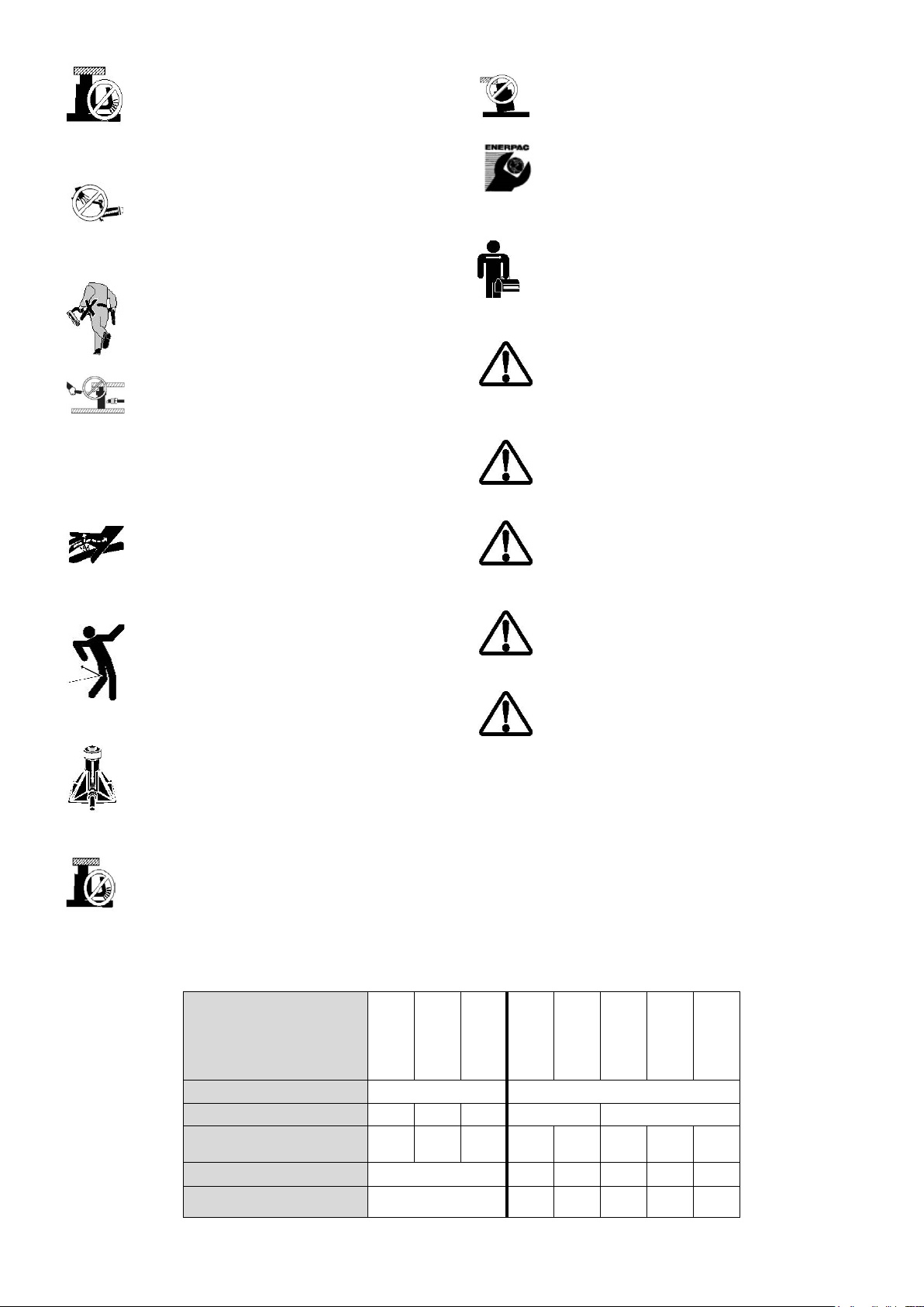
2.0 SAFETY PRECAUTIONS
WARNING: Stay clear of loads suppor ted by
hydraulics. A cylinder, wh en used as a load
lifting device, should ne ver be us e d as a loa d
holding device. After the load has been
raised or lowered, it must always be blocked
mechanically.
WARNING: use only rigid pieces to hold
loads. Carefully select steel or wood blocks
that are capable of supporting the load.
Never use a hydraul ic cylinder as a shim or spac er in
any lifting or pressing application.
WARNING: Wear proper personal protective
gear when operating hydraulic equ ipm ent .
DANGER: To avoid personal injury keep
hands and feet away from cylinder and
workpiece during operation.
WARNING: Do not exceed equipment
ratings. Never att empt to lift a lo ad weighing
more than the capacity of the cylinder.
Overloading causes equipment failure and possible
personal injury.
A DANGER is only used when your action or lack of
action may cause serious injury or even death.
1
CAUTION: Do not connect a jack or cylinder
to a pump with a higher pressure rating.
Never set the relief valve to a higher
pressure than the maximum rated pressure
of the pump. Higher settings may result in
equipment damage and/or personal injury.
WARNING: The system operatin g pressure
must not exceed the pressure rating of the
lowest rated component in the system.
Install pressure gauges in the system to monitor
operating pressure. It is your window to what is
happening in the system.
Page 2
CAUTION: Avoid damaging hydraulic hose.
Avoid sharp bends and kinks when routing
hydraulic hoses. Us ing a bent or kinked hose
will cause severe backpressure. Sharp
bends and kinks will internally damage the
hose leading to premature hose failure.
CAUTION: Do not drop heavy objects on
hose. A sharp impact may cause internal
damage to hose wire strands. Applying
pressure to a damaged hos e may cause it to
rupture.
IMPORTANT: Do not lift hydraulic
equipment by the hoses or swivel couplers.
Use the carrying handle or other means of
safe transport.
CAUTION: Keep hydraulic equipment away
from flames and heat. Excessive heat will
soften packings and seals, resulting in fluid
leaks. Heat also weakens hose materials
and packings. For optim um performance do
not expose equipment to temperatures of
65°C [150°F] or higher. Protect hoses and
cylinders from weld spatter.
DANGER: Do not hand le pres surized h oses.
Escaping oil under pressure can penetrate
the skin, causing serious injury. If oil is
injected under the skin, see a doctor
immediately
WARNING: Only use hydra ulic cylinders in a
coupled system. Never use a cylinder with
unconnected couplers. If the cylinder
becomes extrem ely overloaded, com ponents
can fail catastrophically causing severe
personal injury.
WARNING: be sure setup is stable before
lifting load. Cylin ders should be placed on a
flat surface that can support the load. Where
applicable, use a cylinder base for added
stability. Do not weld or otherw ise modif y the
cylinder to attach a base or other support.
CAUTION: Avo id situations where loads ar e
not directly center ed on the c ylinder plunger.
Off-center loads produce considerab le strain
on cylinders and plungers. In addition, the
load may slip or fall, causing potentially
dangerous results.
CAUTION: D istribute the load evenly across
the entire saddle surface. Always use a
saddle to protect the plunger.
IMPORTANT: Hydraulic equipment must
only be serviced by a qualified hydraulic
technician. For repair service, contact the
Authorized ENERPAC Service Center in
your area.
WARNING: In case of leakage contact
ENERPAC parts. Standard grade parts will
break causing personal injury and property
damage. ENERPAC parts are designed to fit
properly and withstand high loads.
WARNING: Do not use electric pum ps in an
explosive atmosphere. Adhere to all local
and national electrical codes. A qualified
electrician must do installation and
modification
WARNING: Start the pump with the valve in
the neutral position to prevent accidental
cylinder operation. Keep hands clear of
moving parts and pressurized hoses.
WARNING: These pumps have internal
factory adjusted rel ief valv es , which m ust not
be repaired or adjusted except by an
Authorized Enerpac Service Center.
CAUTION: To prevent damage to pump
electric motor, check specifications. Use of
incorrect power source will damage the
motor.
CAUTION: Check motor rotation dir ection to
prevent damage to hydraulic pump (See 4.0
installation)
PUMP MODEL
RESERVOIR CAPACITY (L) 40 150
OUTLETS (points) 2 4 6 2 4
FLOW (l/min) at 700 BAR 1,3 0,45 0,45 2,8 4,2 0,9 1,4 2,1
2
MOTOR POWER KW 5,5 7,5 11 5,5 7,5 11
WEIGHT (Kg) 240 488 526 475 488 526
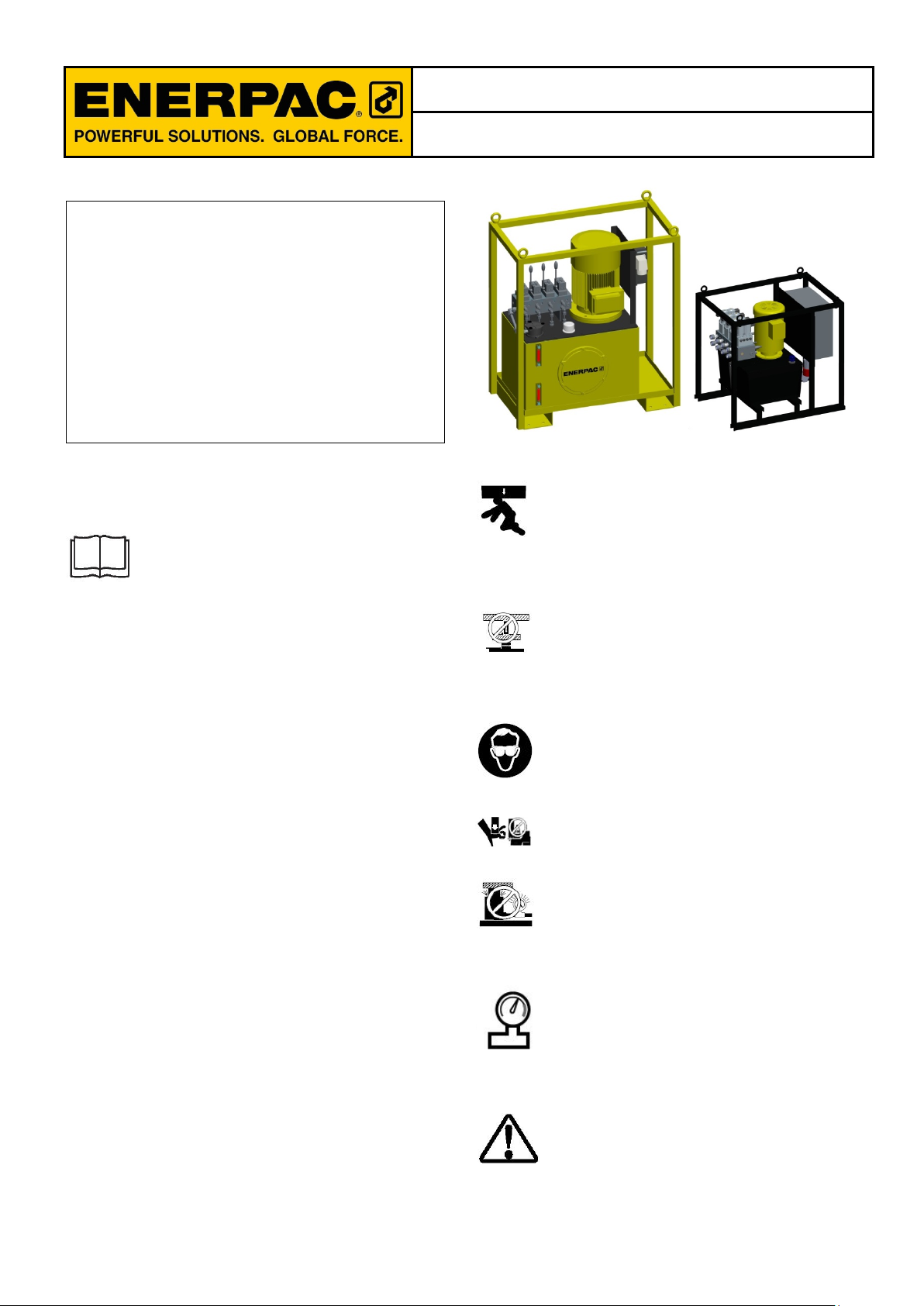
3.0 SPECIFICATIONS
SFP213SW
SFP213MW
The system is composed by a powerpack which
commands 4 double acting cylinders.
There are different m odels of powerpack depe nding on
the number of outlets and flow. Check in the next table
the features of the powerpack concerning to the
equipment acquired
SFP404SW
SFP404MW
SFP604SW
SFP604MW
SFP228SW
SFP228MW
SFP242SW
SFP242MW
SFP409SW
SFP409MW
SFP414SW
SFP414MW
SFP421SW
SFP421MW
Page 3

4.0 INSTALLATION
Visually inspect all components for shipping damage.
Shipping damage is not covered by warranty. If
shipping damage is found, notify carrier at once. The
carrier is responsible for all repair and replacement
costs resulting from damage in shipment.
Install or position the pump to ensure that air flow
around the motor and pump is unobstruc ted. Keep the
motor clean to ensure maximum cooling during
operation.
1. The disconnection and line circuit protection to be
provided by customer. Line circuit protection to be
115% of motor full load c urrent at maxim um pressure
of application.
IMPORTANT: T he pumps with reservoir of 40 L. have
the motor rotation direction sense. When connect the
male plug to the e lectr ic main power, be s ur e tha t th ere
is in the cor rect phase. If not, change th e phase of th e
motor.
4.3 Hydraulic connections
IMPORTANT: Eliminate the presence of side load
forces when using hydraulic cylinders. Side load can
occur through:
1. An eccentric load on the plunger.
2. A horizontal load on a structure.
3. A structure and/or cylinder misalignment.
4. Non synchronized lifting actions.
5. Non stable cylinder base support.
Always use a flat, hard surface as a cylinder support
plate. Use a low friction mat erial on top of the saddle.
To reduce cylinder offset loading, optional CATGswivel saddles are available. Always use grease
underneath swivel saddles.
IMPORTANT: It is mandatory that the operator has a
full understanding of all ins tructions, saf ety regulations ,
cautions and warnings, be fore starting to operate any
of this high force tool equipment. In case of doubt,
contact Enerpac.
4.1 Transportation
WARNING: On double-acti ng cylinders be certain that
hoses are connected to BOTH couplers. Ne ver attempt
to pressurize a do uble-acting cylinder if only one hose
is connected.
IMPORTANT: T o dec om press ports prior t o con nectin g
hoses, move the manua l va lve s ev eral t imes in position
advance and retract with the motor switched off
(manual valves). For solenoid valves turn clockwise
completely the valve handl er in every valve as showed
in the picture (previous unlock the locknut) and leave
finally valves deactivated.
For transportation the frame has two forklift truck
pockets that make available for forklift lift, and four
hoisting certified eyes for lifting with cranes.
dwg 1
4.2 Electric connections
The pump is factory equipped with a 3
phase electrical plug for the given voltage,
altering the plug t ype shoul d only be done by
a qualified electrician, adhering to all applicable local
and national codes.
The plug supplied is set as follow: 3+N+PE 380V 16 A
Connect the hydraulic hoses using the following
diagram.
Port A to the advance side of the cylinder
Port B to the retract s i de of the cylinder (on l y for double
acting cylinders, for single acting cylinder leave it
disconnected).
Follow the next steps to correctly connect the hos es :
1. Keep cylinder con nected to a hydraulic system with
a fluid cleanliness level minimum of NAS 1638 Class 6.
2. Remove dust covers/rubber plugs from oil ports
3. Inspect all threads and fittings for signs of wear or
damage and replace as needed.
4. Clean all threads and fittings.
5. Make hydraulic connections for double-acting
cylinders using t wo hoses.
6. Fully hand-tighten all couplers. Loose coupler
connections will block the flow of oil between the pump
and the cylinder.
7. Check for leaks in system and have repaired by
qualified personnel.
3
Page 4

4.4 Flow level
Check the oil level of the pump prior to start-up, if
necessary add oil by rem oving the plug f rom the top of
the reservoir. The reservoir is full when the oil level
reaches the top of the sight glass.
IMPORTANT: Add oil only when all system
components are fully retracted, otherwise the system
will contain more oil than the reservoir can hold.
5.0 OPERATION
5.1 Manual valve Control
Some models have been design ed to be operated 2, 4
or 6 manual valves, one per output (depend on the
model type:
To move the cylinder moves the handler of the valve
according to the desired movement. The movement
advance or retract is described in a label on the valve.
1. Cylinder 4 selector: This selector actives the
movement of cylinder 4
2. Cylinder 3 selector: This selector actives the
movement of cylinder 3
3. Cylinder 2 selector: This selector actives the
movement of cylinder 2
4. Cylinder 1 selector: This selector actives the
movement of cylinder 1
5. Retracting plunger: Pushing this button the flow of
the port A goes to tank, therefor e in a general purpose
cylinder the plunger goes in.
6. Advancing plunger: Pushing this button the flow of
the port A goes to the c ylinder, therefore in a general
purpose cylinder the plunger goes out.
7. Emergency button: Push ing this button the machine
stops all the movements.
5.3 Electric panel description
On the electric panel (models with solenoid valves)
there are the necessary controls to switch on the
machine.
dwg 2
5.2 Pendant Control
Some machines (models with solenoid valves) have
been designed to be operated by a remote control
connected to the electric cabinet with a 10 m cable in
the connector Nr 6 (see dwg 3).
Through this device the operator can operate every
cylinder (2, 4 or 6 cylinders depending on model).
Therefore it is important to familiarize yourself with
every button. See the next explanation for it:
dwg 3
dwg 4
1. Main electrical switch
2. Power on led
3. System Alarm Light
4. Reset Pushbutton
5. Start/Stop Motor Pushbutton
6. Decompress Pushbutton
7. Pendant Control Connector
8. Power supply connector
5.4 Turning the powerpack on
5.4.1 Pumps with manual valves
To turn the motor on following the next steps:
1. Turn the main switch to the right on the electrical
cabinet
2. Press the motor starter button for 3 seconds.
4
Page 5

Now the machine is able to work. Use the manual
valves to move the cylinders as explained in the
paragraph 5.1.
5.4.2 Pumps with solenoid valves
2. Push decompress button in the electric cabinet
3. Push at the same time the button up in the pendant
The solenoid valve will move to leave free way to the
pressurized line.
To turn the motor on following the next steps:
1. Turn the main switch (Nr 1) to the right on the
electrical cabinet
2. Deactivate the emergency stop button (on the
pendant).
3. Press the reset button to reset the security system
after the emergency button have been activated (Nr 4)
4. Press the motor starter button for 3 seconds (Nr 3)
Now the machine is able to work with the pen dant. U se
the pendant to move the cylind ers as explained in the
paragraph 5.2.
5.5 Setting up the relief valve
The powerpack has been designed to set the
relief valves u p by the operator. T he maximum
pressure of the relief valve is between 10 and
700 bar. For this propose the op erator needs
the next tools:
1. Plain slot screwdriver (1 unit)
2. Spanner of 13 mm (1 unit)
3. Manometer 0-1000 bar (f or press ures up to 700 bar )
(4 units).
Manometers must be connected to the MP port (1/4”
NPT), in order to know the pressure in each line.
To set the relief valve up, follow the next steps:
1. Connect the output to one cylinder
2. Unblock the hexagonal nut of the relief valve.
3. Turn the bolt with the screwdriver totally (counter
clockwise)
4. Turn the bolt a q uart er t ur n in or der to op en the relief
valve (clockwise)
5. Press the motor starter button for 3 seconds (Nr 3)
6.0 MAINTENANCE
6.1 Check Oil Level
Check the oil level of the pump prior to start-up, and
add oil, if necessary, by removing the fill port cap.
Always be sure cylinders are fully retracted before
adding fluid to the reservoir.
6.2 Change Oil and Clean Reservoir
Enerpac HF oil is a crisp blu e color. Frequently check
oil condition for contam ination by comparing pump oil
to new Enerpac oil. As a genera l rule, completel y drain
and clean the reservoir every 250 hours, or more
frequently if used in dirty environments.
NOTE: This procedure requires that you remove the
pump from the res ervoir. Work on a clean bench and
dispose of used oil according to local codes.
1. Unscrew the bolts holding the cover plate to the
reservoir and lift the pum p unit out of the reser voir. Be
careful not to damage the filter screen.
2. Pour all oil out of the reservoir.
3. Thoroughly clean t he reser voir and reser voir m agnet
with a suitable cleaning agent.
4. Reassemble the pump and reservoir
5. Fill the reservoir with clean Enerpac hydraulic oil.
The reservoir is full when oil level is in middle of the
sight gauge
6.3 Changing the Filter Element
The f ilter element shou ld be replaced e very 250 hours,
or more frequently in dirty environments. The filter
manifold is equipped with a 25 psi (1,7 bar) b ypass to
prevent over pressure rupture if filter plugging occurs
and with a small gauge that shows the pressure when
the filter is dirty (see in the hydraulic diagrams num 8).
6. Extract the cylinder plunger up to final. (When the
plunger reaches the final of the stroke the pressure
gets up. See in the manometer the m aximum pressure
reached).
7. Turn the bolt (counter clockwise to decrease the
pressure, or clockwise to increase the pressure) with
the screw driver to reach the desired pressure.
8. Block the nut with the spanner to block the relief
valve.
5.6 Decompressing system
With the motor switched off:
1. Select cylinders to decompress in the pendant
5
7.0 TROUBLESHOOTING GUIDE
Only qualified hydrau lic technicians should ser vice the
pump or system components. A system failure may or
may not be the result of a pump malfunction. To
determine the cause of the problem, the complete
system must be included in any diagnostic procedure.
Refer to the troubleshooting chart for a list of typical
cylinder problems and possible causes. The
troubleshooting chart is not all-inclus ive, and should be
considered only as an aid to help diagnose the most
common problems. For repair service, contact your
local Authorized Enerpac Service Center.
Page 6

7.1 Troubleshooting chart
PROBLEM
POSSIBLE CAUS E
SOLUTION
Cylinder does not advance,
A. Oil level in pump reservoir is low.
A. Add oil to pump.
authorized Enerpac service center
Cylinder advances, but does not
A. Leaking oil connection.
A. Check that all connections are
authorized Enerpac service center.
Cylinder does not retract
A. Pump reservoir overfilled.
A. Drain oil level to full mark.
retract the cylinder
Wrong motor rotation direction
A. The phase of the motor is wrong
A change the phase of the motor
Alarm light switched on
A. Thermic protection is down.
A. Open the electric cabinet and
Have pump serviced by an
authorized Enerpac service center.
advances slowly or in spurts
hold pressure.
B. Release valve open.
C. Loose hydraulic coupler.
D. Air trapped in system.
E. Cylinder plunger binding
B. Leaking seals.
C. Internal leakage in pump.
B. Loose hydraulic coupler.
C. Air trapped in system.
D. Oil flow to cylinder blocked.
E. Hose internal diameter too narrow.
F. No load on a load return cylinder
B. Close pump release valve.
C. Check that all couplers are fully
tightened.
D. Remove air.
E. Check for damage to cylinder.
Have cylinder serviced by an
tightened.
B. Locate leak(s) and have
equipment serviced by an Enerpac
service center.
C. Have pump serviced by an
B. Check that coupler(s) are fully
tightened.
C. Remove air.
D. Check that coupler(s) are correctly
connected fully tighten ed a nd valving
is functioning properly.
E. Use a larger diameter hose.
F. CLL and CLS cylinders are load
return. Apply load force to completely
8.0 ATTACHED DO CUMENTATION TABLE
In this manual other documents hav e been attac hed which are necessary t o interpret this manual. I n th e nex t tab le
there is an index to facilitate finding these documents. Push on the paper icon
150 L RESERVOIR 40 L RESERVOIR
MANUAL VALVES SOLENOID VALVES MAN. VALVES SOLEN. VALVES
PUMP MODEL
ASSEMBLY DRAWING
HYDRAULIC SCHEME
SPARE PARTS
B. DC protection is down.
SFP228MW
SFP242MW
SFP409MW
SFP414MW
SFP421MW
switch up the thermic protection
B.
to show them.
SFP228SW
SFP242SW
SFP409SW
SFP414SW
SFP421SW
SFP213MW
SFP404MW
SFP213SW
SFP404SW
SFP604MW
SFP604SW
CE DECLARATION
6
 Loading...