

Instruction Manual
M
ANU
AL
Super Boom Lift
SBL1
SBL1100
- 1100 Sh. Te Hydraulic Gantry -
100
Document number ED.02518.001.R03.ENG
Issued
Revision No. 3
Revision Date 27-06-2011
23-12-2010

Dear customer,
This is the manual for the Enerpac product you have purchased.
This manual contains important information for the correct use and safe
operation of the machine.
If this manual should become wholly or partly unusable, you can order a new
replacement copy of it, making reference to the number shown on the cover.
Enerpac reserves the right to modify this manual at any time, at its discretion
or according to its advancing insight.
ED.02518.00.001.R03.ENG
Page 2

Contents
Contents ______________________________________________________________________ 3
Introduction ___________________________________________________________________ 5
1. General Information _________________________________________________________ 7
1.1. General _______________________________________________________________________ 7
1.2. Manufacturer’s address __________________________________________________________ 7
1.3. Declaration ____________________________________________________________________ 7
1.4. Identification __________________________________________________________________ 7
1.5. Liability _______________________________________________________________________ 8
1.6. Appropriate use ________________________________________________________________ 8
1.7. Application limits _______________________________________________________________ 8
1.8. The basic principle ______________________________________________________________ 9
1.9. General Specifications ___________________________________________________________ 9
1.10. Machine overview ___________________________________________________________ 10
2. Safety ____________________________________________________________________ 11
2.1. Mandatory protective gear while working with or on the system _______________________ 12
2.2. Explanation of symbols in this manual _____________________________________________ 12
2.3. Explanation of symbols on the machine ____________________________________________ 13
3. Preparation for a lifting operation _____________________________________________ 14
3.1. Lifting capacity of the units ______________________________________________________ 15
3.2. Capacity of the Side shift or Lug __________________________________________________ 18
3.3. Capacity of the Header beam ____________________________________________________ 19
3.4. Surface loading for full support of the skid tracks ____________________________________ 19
3.5. Surface load with filler material under the skid tracks ________________________________ 21
3.6. Maximum permissible wind loading _______________________________________________ 23
4. Explanations of Methods ____________________________________________________ 24
4.1. Storage ______________________________________________________________________ 24
4.2. Handling _____________________________________________________________________ 25
4.3. Placement of the skid tracks _____________________________________________________ 29
4.4. Placement of the unit __________________________________________________________ 36
4.5. Connection of power cable ______________________________________________________ 36
4.6. Erect the mast ________________________________________________________________ 37
4.7. Mounting the header beams _____________________________________________________ 40
4.8. Mounting the side shift _________________________________________________________ 41
ED.02518.00.001.R03.ENG
Page 3

5. Before raising the load ______________________________________________________ 42
6. Checklists _________________________________________________________________ 44
6.1. Preparation for a lifting operation ________________________________________________ 44
6.2. Setting up the portal system _____________________________________________________ 45
6.3. Before raising the load __________________________________________________________ 45
7. The operation of the machine _________________________________________________ 46
7.1. The control panel on the unit ____________________________________________________ 47
7.2. The Intellilift control panel ______________________________________________________ 49
7.3. Manual control ________________________________________________________________ 50
7.4. Intellilift control _______________________________________________________________ 50
7.5. Mechanical locking ____________________________________________________________ 62
8. Special applications _________________________________________________________ 64
8.1. Tilting a load __________________________________________________________________ 64
9. Maintenance ______________________________________________________________ 67
9.1. Lubrication Points _____________________________________________________________ 68
9.2. Maintenance of the hydraulic system _____________________________________________ 69
9.3. Adjust guides _________________________________________________________________ 72
9.4. Lubricating the rams ___________________________________________________________ 76
9.5. Roller Chain __________________________________________________________________ 78
Appendices ___________________________________________________________________ 80
Appendix A Checklist for work preparation ______________________________________________ 80
Appendix B Checklist for setting up the machine __________________________________________ 82
Appendix C Checklist for lifting the load _________________________________________________ 83
Appendix D Hydraulic fluid safety information sheet ______________________________________ 85
Appendix E Skid track requirements ____________________________________________________ 90
ED.02518.00.001.R03.ENG
Page 4

Introduction
Introduction
Dear customer,
In purchasing the SBL portal lift system, you have bought a quality product from the
Enerpac company.
We thank you for the confidence you place in us by your purchase of this portal lift
system.
Operating an SBL system is only permitted if you are certified by Enerpac as an
authorised operator.
In order to be able to use the portal lift safely, we urgently request you to read this
manual thoroughly before you start working with the machine.
The manual is made up in such a way that you are comprehensively provided with
information during the course of the working situation. The whole consists of
comprehensive directions and instructions about maintenance, safe use, safe
practices and specific safety instructions. It is necessary, important and
advantageous to the proper function and reliability of your SBL portal lift system, and
to maintain its value, to take these directions and instructions into account.
Note:
In the rest of this manual, the portal lift is also referred to by the term
“Machine”.
NOTE:
This manual is part of the machine.
Only operate the machine after you have been trained, and taking this manual into
account.
Follow the safety instructions exactly!
Also observe the applicable directions to prevent accidents and the generally
recognised safety regulations, as well as the health and safety inspectorate’s
regulations.
All information, illustrations and technical data in this manual are applicable to the
situation existing at the time of publication.
We strive continuously to improve our products and therefore reserve the right to
implement improvements and changes whenever it is necessary and possible to do
so, without any obligation to apply improvements or changes to models purchased
previously.
If this manual should become wholly or partly unusable,
you can order a new replacement copy of it, making reference to the number shown
on the cover.
This manual is continually updated. We welcome suggestions which make the reading
of this manual or the use of the SBL system easier or safer.
ED.02518.00.001.R03.ENG
Page 5

even death.
Introduction
Despite the fact that this manual has been drafted with great care, we cannot
guarantee that it does not contain any errors. The interpretation and use of that
described in this document and possible consequences through improper use of the
system are wholly the responsibility of the user. Enerpac shall under no
circumstances accept responsibility for such improper use.
Improper use of the machine or failure to take the changes
indicated in this manual into consideration may result in
accidents causing damage not only to the machine itself, but also
to objects and goods in its vicinity or mounted to the machine, as
well as injuries to people in the immediate area, and possibly
All rights reserved. Nothing in this publication may be duplicated, stored in an
automated database or made public in any form or in any manner, whether
electronic, mechanical, by photocopying, recording or any other means, without prior
written approval by Enerpac.
We hope you find your Enerpac machine very useful.
Enerpac.
ED.02518.00.001.R03.ENG
Page 6

General Information
Enerpac Integrated Solutions B.V.
1. General Information
The manual contains fundamental instructions that must be taken into consideration
in preparing for a lifting operation, and for assembly, use and maintenance. For this
reason it is essential that the user read this manual before working with or on the
machine, and it must always be available for reference.
Points that must be followed are mentioned, not only in the safety chapter; in other
chapters too there are specific directions that must be read and followed.
1.1. General
This manual applies to a complete SBL1100 system.
1.2. Manufacturer’s address
Enerpac Integrated Solutions B.V.
Opaalstraat 44 7554 TS
Hengelo The Netherlands
Tel. +31 - 74 - 242 20 45
Fax. +31 - 74- 243 03 38
E-mail: info.hengelo@Enerpac.com
1.3. Declaration
EC Conformity declaration according to Directive.
1.4. Identification
Each unit; header beam, side shift and skid track is provided with a type plate as
illustrated below.
The type plates are official documents and must not be altered or made
ED.02518.00.001.R03.ENG
illegible!
Page 7

General Information
1.5. Liability
In the risk analysis conducted by Enerpac, intended usage and reasonably
foreseeable incorrect usage of the SBL portal lift system were assessed. The
instructions in this manual came into being based upon this analysis.
It is expected of the user of the SBL portal lift system that he or she has read and
understood this manual.
In cases of doubt about the use or application of this machine, always make contact
with Enerpac for advice and recommendations.
Unauthorised alterations to the machine may have a deleterious effect on the
characteristics of the machine and may disrupt the control functions. Unauthorised
alterations therefore annul any resultant damage claims against the manufacturer.
1.5.1. Limitations of liability:
We accept no liability whatsoever:
- for damage as a result of this equipment;
- to objects and third party equipment;
- to vehicles;
- for personal injury.
1.6. Appropriate use
The SBL1100 hydraulic portal lift is a four point lifting system. All four units must
always be used when lifting or transferring various objects. The centre of gravity
(C.O.G.) of the load must always remain within the four feet and under the header
beam.
The machine has been designed to be controlled using the associated Intellilift
remote control. Using this, the user can and must remain outside the range of the
machine while working with it.
Additional possible applications for the machine with the associated warnings are to
be found in Chapter 8, “special applications”.
The machine must not be used in potentially explosive environments.
1.7. Application limits
The application limits for the capacity, lifting height, skew, wind and environmental
influences are the maxima either calculated or tested by the manufacturer. During
practical applications, you must bear in mind that, through influences these
characteristics may exercise on each other, they may reinforce each other, and must
then be appropriately altered. Enerpac can advise you on this point.
ED.02518.00.001.R03.ENG
Page 8

General Information
(1)
(2)
(2)
used because they may lock up.
1.8. The basic principle
Each lifting unit consists of a basic frame with its own drive and octagonal telescopic
masts. In each telescopic mast there is an extending hydraulic ram.
The internal propulsive force is provided by a hydraulically driven roller track system.
This reduces the basic loading in comparison with conventional wheels. Moreover, the
resistance when bridging rail systems is reduced. It is impossible for wheels to slip
through!
One of the unique characteristics of the SBL1100 portal lift is the integration of the
power source into the basic frame. In contrast to conventional systems, this means
no separate power source and no hoses or data cables between power source and
units.
The beams across the top of the units create a portal.
The load is affixed to the beam by means of a side shift module or lifting anchor.
1.9. General Specifications
Each separate unit has a load carrying capacity of 2,670 kN.
The exact permissible loading is described in detail in Chapter 3.
The hydraulic pumps have a fixed stroke capacity. The machine's speed is variable
thanks to the built-in frequency controller.
Specification of the power source:
Voltage.......................................................................... :360 to 480 V AC/ 3-phase
Current.......................................................................... :16 A per unit
Frequency...................................................................... :50-60 Hz
Power............................................................................ :7.5 kW per unit (10 hp)
The units feature automatic phase selection according to the rotation direction of the electric motors.
Noise pressure................................................................ :77 dB(A)
.
Temperatures
Minimum operating temperature of the machine.................. :-25°C
Maximum operating temperature of the machine................. :50°C
Minimum storage temperature of the machine.................... :-25°C
Maximum storage temperature of the machine................... :60°C
Minimum storage temperature of the Intellilift control panel.. :20°C/0°C
Maximum storage temperature of the Intellilift control panel. :60°C/45°C
(1)
measured at ear height at nominal loading one metre away from any unit’s
electric motor
(2)
While charging the battery.
NOTE:
ED.02518.00.001.R03.ENG
There is a risk of ice accretion at temperatures below 0ºC.
If ice has accreted on machine components, they cannot be
Page 9
2
2
3
4
3
4
1
1
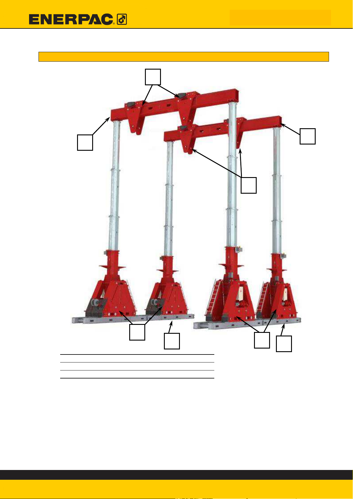
1.10. Machine overview
General Information
1) Skid track Required
2) Lift unit Required
3) Header beam* Required
4) Side shift unit** Required
*The figure shows a 10-metre beam. Beam dimensions and material may vary from
customer to customer.
** The figure shows an HBS6000 Side Shift unit. It is also possible to opt for a
different type of side shift, or fixed anchors.
ED.02518.00.001.R03.ENG
Page 10

Safety
2. Safety
Points that must be followed are covered not only in this chapter; in other chapters
too there are specific safety directions that must be read and followed.
It is very important to inspect the condition of the SBL system before every individual
start-up, given the fact that the slightest defect may have disastrous, and in some
cases fatal, consequences.
Keep your equipment clean. Badly maintained equipment can cause time wastage
and lead to permanent damage to the equipment and/or it surroundings.
Do not use equipment, whether loaded or not, while people are in the vicinity of the
equipment or object. The SBL series has been designed for used without manpower
inside the range of the portal lift, and must be operated according to the instructions.
Only operate the SBL system if you have been certified by Enerpac as an authorised
operator.
Only use original Enerpac spares to repair machine faults.
Maintain concentration during the work. Carelessness may result in serious injuries to
others, and possibly even death.
Additional lifting gear and accessories such as hawsers, shackles etc. must comply
with the legal requirements imposed in the country of use.
Enerpac is not liable for improper use of such accessories in combination with the SBL
system.
Adhere to the checklists during all work activities: during
preparation for the lifting operation, system construction, and for
lifting the load.
Failure to adhere to the checklists may result in serious injury to
the user, possibly even death.
ED.02518.00.001.R03.ENG
Page 11
Safety
2.1. Mandatory protective gear while working with or on the system
Ensure that you and other people in the vicinity and during the operation of the portal
lift wear a safety helmet and that the applicable safety regulations are observed.
Wear safety footwear, safety goggles, and, when not using the remote control, safety
gloves*.
*We strongly advise against wearing safety gloves while using the Intellilift remote
control.
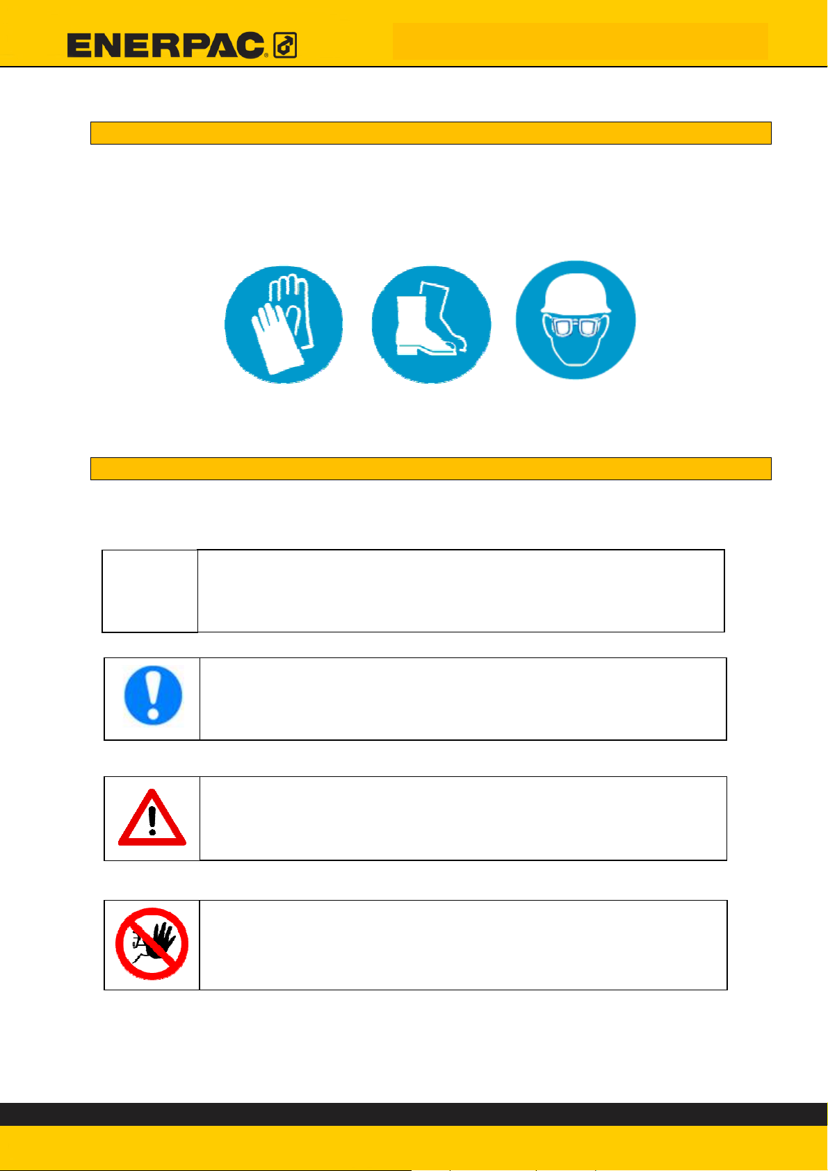
2.2. Explanation of symbols in this manual
The following symbols are used in this design manual to elucidate the various specific
instructions.
Indicates to the user that something needs to be filled in on the
checklist.
Gives the user hints and tips on simple control procedures and
work activities
General warning to the operator for possible damage to
equipment and to the environment in general.
Draws the user's attention to risks to personnel if work
instructions are not followed precisely
ED.02518.00.001.R03.ENG
Page 12
Safety
4 stickers (On protective caps)
2
2
1
4
3
1
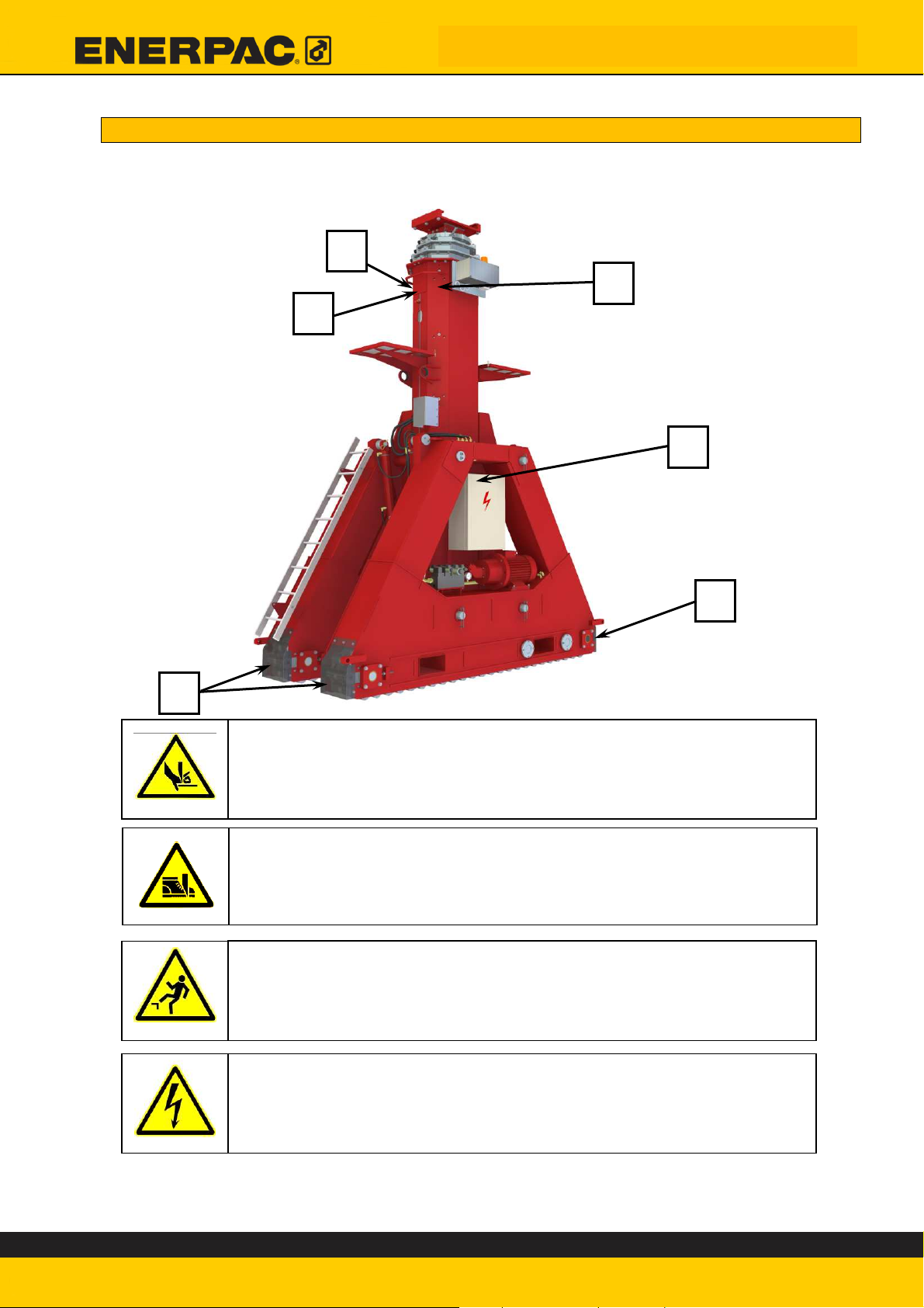
2.3. Explanation of symbols on the machine
Instructions on labels applied directly to the machine must be followed without
question, and always be kept in a fully and properly legible condition.
1. Risk of trapping parts of the hand
2. Risk of trapping parts of the foot
3. Risk of falling
4. Risk from electricity
4 stickers (Around the bottom ram)
2 stickers (visible from stage)
2 stickers (On motor and Switchbox)
ED.02518.00.001.R03.ENG
Page 13
Preparation for a lifting operation
3. Preparation for a lifting operation
In this chapter, the essential preparations for a lifting preparation are
comprehensively described.
Before this preparation can be started, certain information must be known:
• Mass of the load.
• Centre of gravity of the load.
• Dimensions of the load.
• Maximum lifting height.
• Allowable pressure on the subsoil before subsidence happens.
First, the position of the load’s centre of gravity within the units should be
determined. Then the maximum lifting height is determined.
Thereafter, it is checked whether the following details are adequate:
• Lifting capacity of the most heavily loaded unit.
• Capacity of the side shift.
• Capacity of the header beams.
• Load capacity of the subsoil.
Finally, the maximum acceptable wind speed should be calculated.
This preparation results in:
A checklist for use while setting up the machine.
A checklist the operator must follow during use of the machine.
It is of the utmost importance to read this whole chapter
carefully before setting up the machine.
Failure to prepare correctly for a lifting operation may
result in total loss of machine stability during use.
ED.02518.00.001.R03.ENG
Page 14
Preparation for a lifting operation
=
⋅
3.1. Lifting capacity of the units
Determine the maximum for the lifting height needed for your lifting operation.
3.1.1. Maximum load
The portal lift system comprises four units. Given the fact that each unit is
provided with a telescopic hydraulic ram, the capacity varies according to the
phase. The working pressure for each step is around 350 bar. This results in the
following lifting capacities:
st
1
stage: 2670 kN, → lifting height: 0 mm to 2934 mm
nd
2
stage: 1750 kN, → lifting height 2934 mm to 5698 mm
nd
3
stage: 1000 kN, → lifting height: 5698 mm to 7632 mm
Theoretically, this means that the maximum loading is
this is only applicable if the load is evenly distributed over the portal lift. In other
words, if the centre of gravity is positioned in such a way that each lifting units
carries exactly the same load. This is naturally a situation that never arises in
practice. In order to prevent overloading of the portal lift, the loading table must
be used.
Dimensions of the units, beams, side shift, and skid tracks.
may be found in Appendix D to G.
This information can be used to determine the required lifting
height.
Fill the maximum lifting height into the checklist in appendix A
1068026704
kN
kN. But
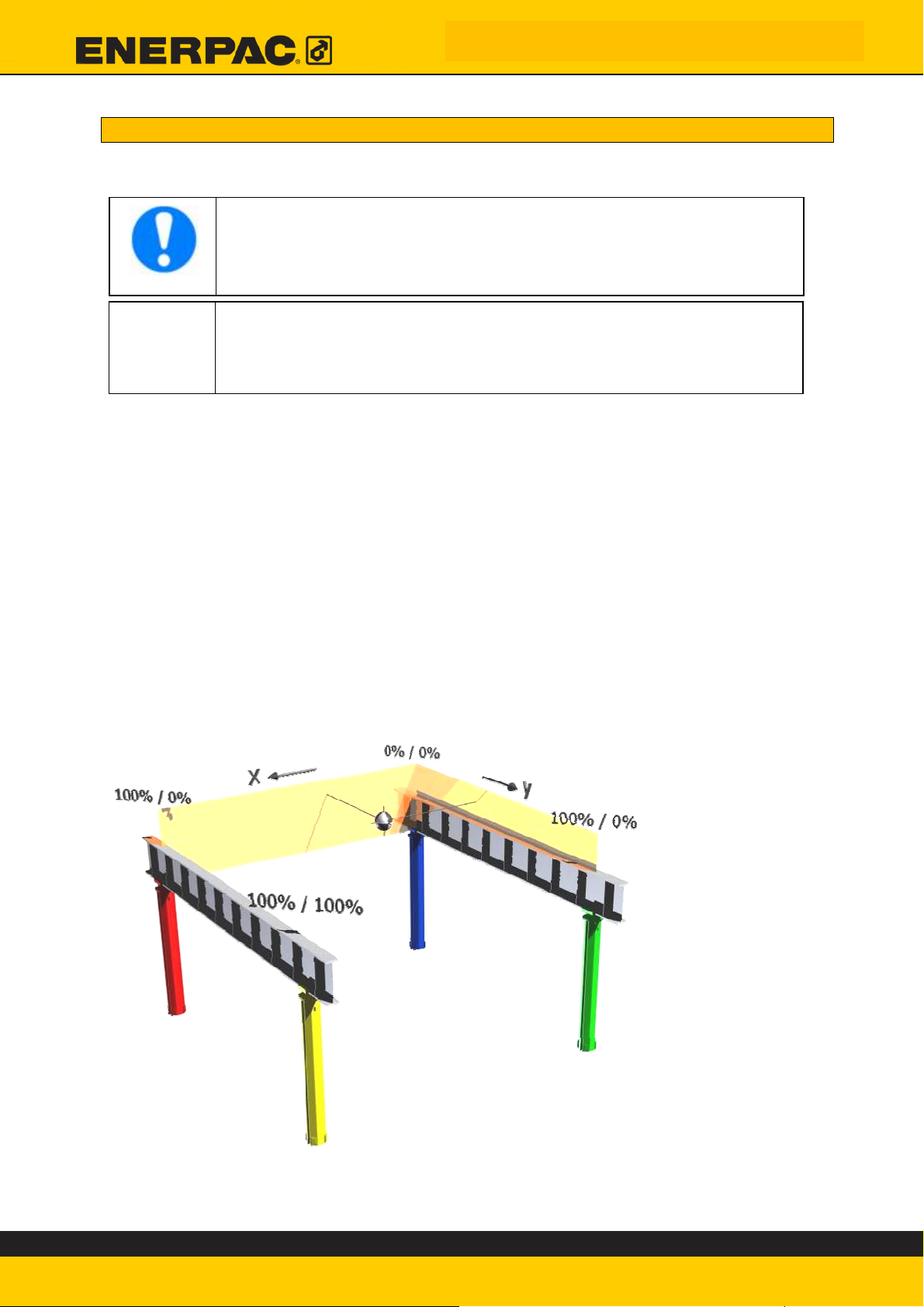
The figure shows the orientation of the table with respect
to the portal lift.
The coloured cells in the load chart correspond to the
lifting units in the figure
ED.02518.00.001.R03.ENG
Page 15
The stability of the system is such that if the COG is positioned in
the centre of the machine, then any movement of the COG out of
the ideal centre will result in reduced stability of the overall
system.
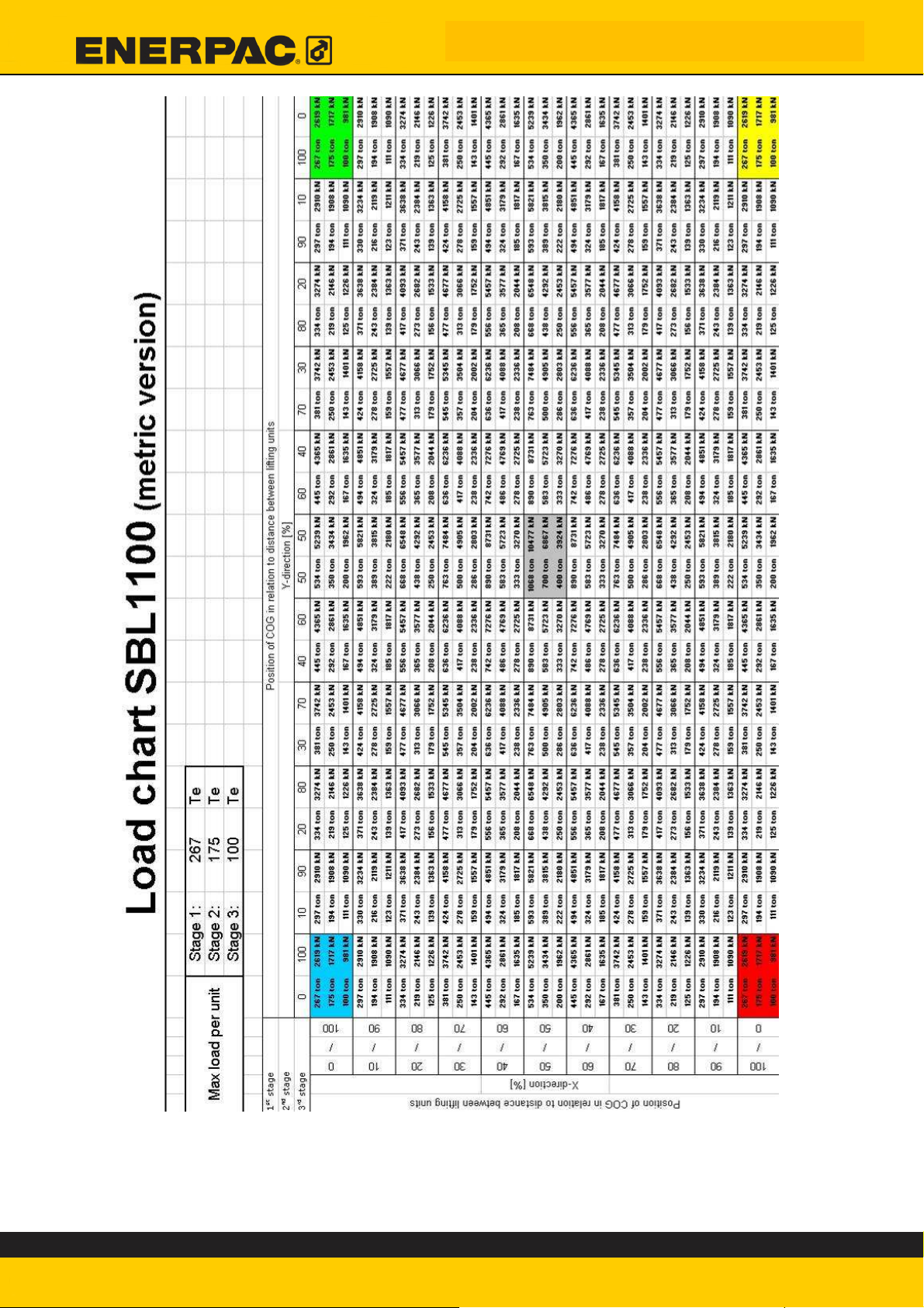
The table on the next page should always be used before and
during side-shift operations.
During this kind of work, the load's centre of gravity (COG) shifts
from one point to another. After this kind of shift, one or two
units will bear more of the load, and the other two will bear less
of it. In order to ensure that the maximum permissible load is
not exceeded for any of the units, it is necessary to consult the
table before each operation.
Use the load chart to fill the maximum force per unit occurring
during the lifting operation into checklist A
(Only for the unit under the heaviest load)
Preparation for a lifting operation
ED.02518.00.001.R03.ENG
Page 16
Preparation for a lifting operation
This table must always be used for side shift operations. During this kind of work,
the load's centre of gravity (COG) shifts from one point to another. After this kind
of shift, one or two units will bear more of the load, and the other two will bear
less of it. In order to ensure that the maximum permissible load is not exceeded
for any of the units, it is necessary to consult the table before each operation.
ED.02518.00.001.R03.ENG
Page 17
Preparation for a lifting operation
3.1.2. Minimum load
Due to friction in the hydraulic cylinders, it is possible that the extension order of
the first and second step may not be followed properly, due to insufficient loading
of the units. In other words, the units also have a minimum lifting capacity. The
total minimum loading is 50 kN. In most cases, the header beams’ own weight is
sufficient.
3.2. Capacity of the Side shift or Lug
The force on each anchor point cannot under any circumstances be greater than
the capacity of the side shift unit or lug. The capacity of the side shift or lug is
indicated on the documentation provided on delivery.
Use the load chart to fill the minimum force per unit occurring
during the lifting operation into checklist A
(Only for the unit under the lightest load)
Always determine the force on each anchor point. Even for
relatively light loads. This can be done using a centre of gravity
calculation.
The preparer is expected to possess this skill. In case of doubt,
Fill the maximum anchor load into the checklist in
appendix A
ED.02518.00.001.R03.ENG
Page 18
Preparation for a lifting operation
0
,
2
°
3.3. Capacity of the Header beam
The force on each anchor point may not in any case be greater than the capacity
of the header beam. The capacity of the header beams is shown in the beam load
chart.
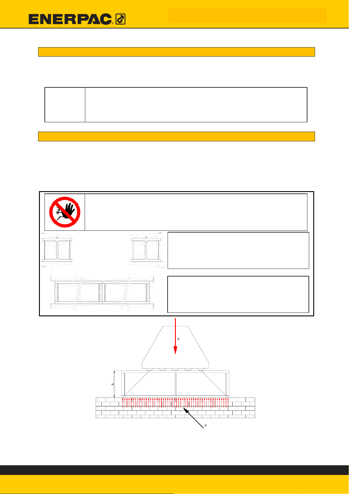
3.4. Surface loading for full support of the skid tracks
If it is not possible to have the underside of the skid tracks 100% supported,
Azobé wood and steel plates must be installed under the skid track – see section
3.5.
The surface load is defined as follows: the load due to the weight exerted on the
subsoil by the guide rails.
Fill the maximum permissible beam load into the checklist
in appendix A
If the following requirements cannot be met: then the skid tracks
must be set up using filler materials.
In this case, the force on the subsoil is determined in chapter
3.5.
The rails may not be skewed in side
view. The angle from the horizontal
plane must be less than 0.2° in both
axes.
0
,
2
°
0
,
2
°
°
2
,
0
The incline angle of the running surface
must not be more than 0.2°.
The surface loading is dependent on the type of guide rails used.
The height h is indicated on the drawing provided with the skid tracks.
The surface loading may be calculated by means of the formulae below; a small
extra safety factor is already included in these formulae.
ED.02518.00.001.R03.ENG
Page 19
Preparation for a lifting operation
1380
+
+
⋅
h
33.54
+
+
⋅
h
1380
400
1380
+
+
⋅
+
+
⋅
h
33.54
15
33.54
+
+
⋅
+
+
⋅
h
Metric system Imperial system
5000100
=
σ
σ = surface load, [metric tonnes/m2] σ = surface load, [short tonnes/ft2]
F = load on a particular foot, [kN] F = load on a particular foot, [kips]
h = rail height, [mm] h = rail height, [inches]
The load F is the maximum load on one particular lifting foot. This is the force
determined in section 3.2 and indicated as the maximum force per unit occurring
during the lifting operation.
Replace parameter F in the formula with this maximum load to determine the
maximum surface load during the lifting work.
Examples:
Metric: The expected maximum load on one of the feet is 1200 kN. The height of
the rail is 400 mm. The resulting maximum surface loading is then:
5000100
=
σ
F
F
7.1*
=
7.1*
50001200100
1197.1*
=
metric Te/m2, or
=
σ
F
11.2079.1
1.19
N/mm2.
7.1*
Imperial: The expected maximum load on one of the feet is 350 kips. The height
of the rail is 15”. The resulting maximum surface loading is then:
=
σ
F
11.2079.1
7.1*
=
The surface load occurring with complete underfilling of the skid
tracks must always be less than the permissible surface load.
The height of the skid tracks is indicated on the drawing provided
with the skid tracks
Fill the maximum surface load into the checklist in
appendix A
11.2035079.1
9,157.1*
=
sh. tonnes/ft2.
ED.02518.00.001.R03.ENG
Page 20
Preparation for a lifting operation
+
=
*.*6.
33
+
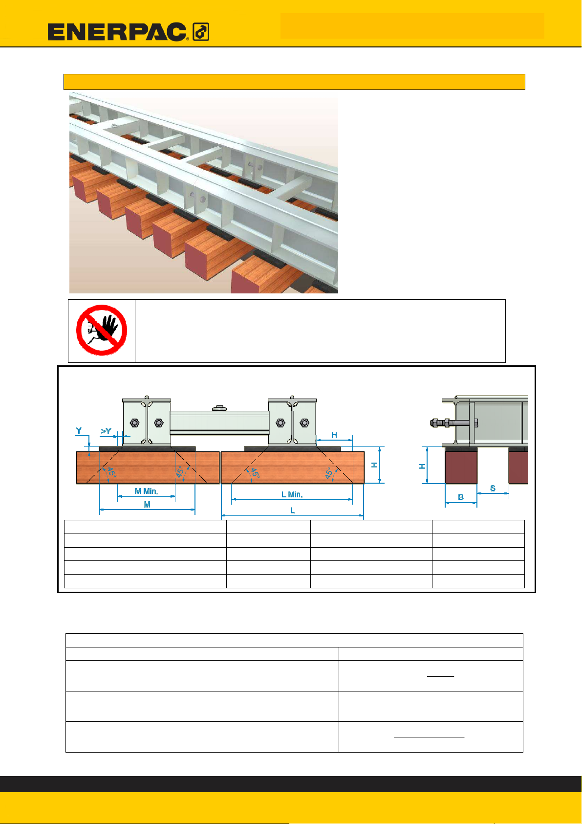
3.5. Surface load with filler material under the skid tracks
If it is necessary to use Azobé
wood under the rails to
compensate for unevenness in
the subsoil, or to create a lower
surface loading, then a number
of matters must be borne in
mind!
The points of attention are
dealt with in this chapter and in
the chapter “Explanations of
Methods”. The preparer must
also go through and
understand section 4.3.
Geometrical requirements for the Filler material:
Only use filler materials in accordance with section 4.3.2
Read section 4.3.2 before proceeding any further in this section.
In case of doubt, consult Enerpac
Description Parameter Requirements Comment
Length of the filler material L > L Min. Max. 914mm
Length between plates M > M Min.
Width of the filler material B > H and > 250 mm
Space in between S < 250 mm
The surface loading may be calculated by means of the formulae below; a small
extra safety factor is already included in these formulae.
Length measurements in metres
Description Formulas
O = filler material ratio
O+=
B
SB
L net. = Effective Length
Please Note: L net can never be greater than 0.914 m
σ = surface load, [metric tonnes/m2]
F = load on a particular foot, [kN]
=
σ
ED.02518.00.001.R03.ENG
Page 21
HLnet *23.0.
100
F
7.1*
OLnet
Preparation for a lifting operation
25.04.
0
+
=
+
=
*.*6.
33
+
61.0*9.0*6.33
+
The load F is the maximum load on one specific lifting foot; this is the force
specified in section 3.2, defined as the maximum force arising during the lifting
operation.
Example:
The expected maximum load on one of the feet is 1200 kN.
B= 400mm 0.40m
H= 300mm 0.30m
S= 250mm 0.25m
The resulting maximum surface loading is then:
O+=
σ
B
61.0+=
SB
HLnet *23.0.
100
F
=
7.1*
m
OLnet
The actual surface load must always be less than the permissible
surface load.
The formulas in this section are based on the
Enerpac Rollertrack
4.0
3.0*23.0.9.0
2
/120
=mton
1001200
7.1*
Fill the maximum surface load, the L, W, H and the S from
the checklist in appendix A
ED.02518.00.001.R03.ENG
Page 22
Preparation for a lifting operation
3.6. Maximum permissible wind loading
Another factor that must be taken into account when lifting is the sidewards
loading. During activities in the open air, the wind exerts a certain force on the
object lifted by the portal, which directly results in a sidewards loading. The
permissible sidewards loading is dependent upon a number of factors, namely the
size of the object, the wind speed and the height of the top beams (lifting height).
This means that, before every lifting operation, it must be checked that the wind
does not present danger.
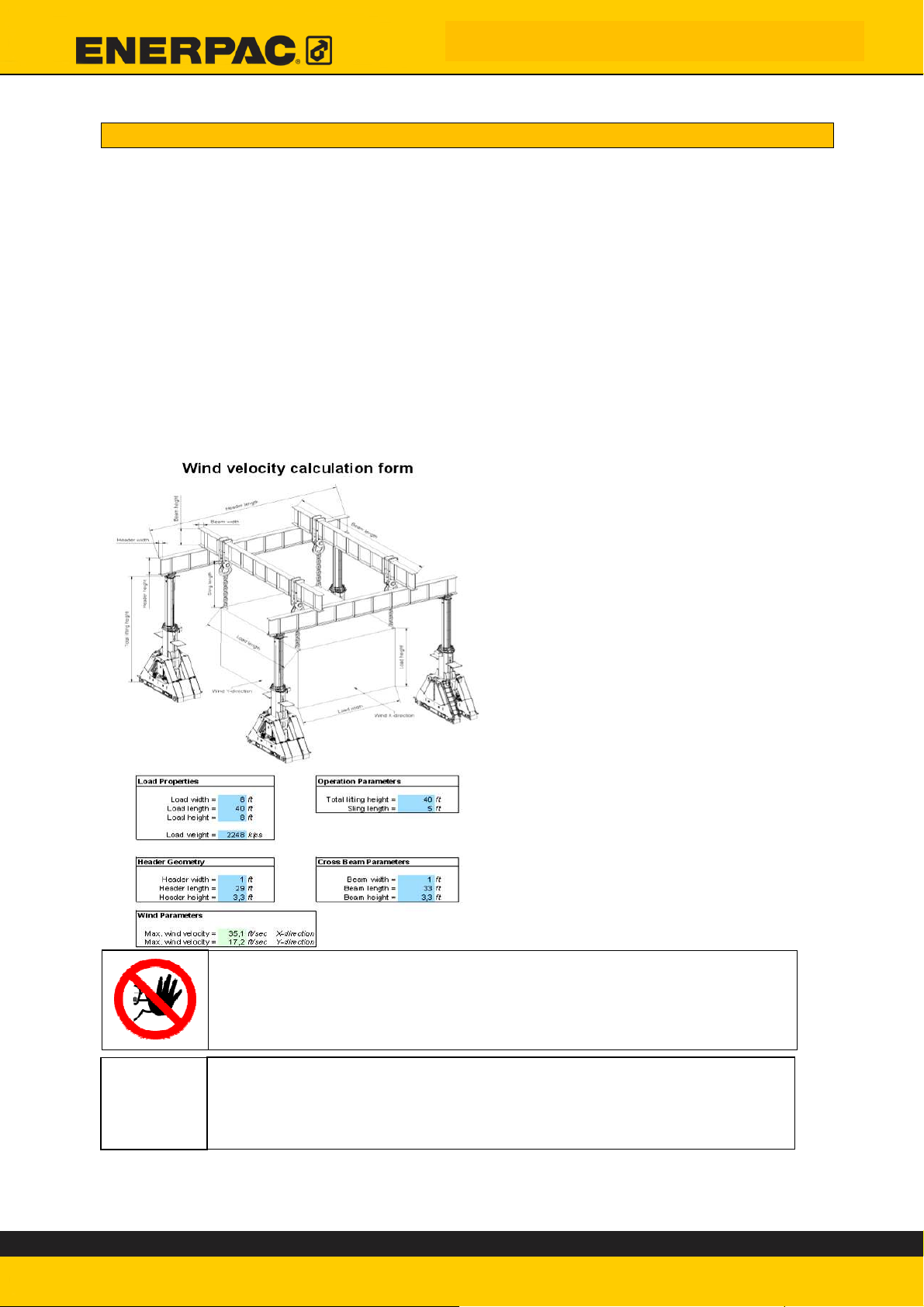
The maximum wind speed is calculated in accordance with a calculation form for
loads; this form can be found on the CD-ROM supplied. The form shows the
maximum permissible wind speed in both directions under different
circumstances.
Under no circumstances whatsoever may lifting operations be carried out when
the wind speed is greater than the values given on the form.
On the left, you will find an example
of a fully completed form:
Only certain parameters have to be
entered. Enter the dimensions
referred to as the outline dimensions
of the object. These are the x-y-z
dimensions of the outline of the
beams and load. The foot
dimensions of the portal lift are
already entered and cannot be
changed. Always start from the most
adverse situation.
Do not forget that the wind speed
and direction may change during
lifting.
When lifting, always assume a worst-case scenario. The wind can
be unpredictable, quickly changing speed and direction. Do not
take any chances: if the wind is strong, that means it's a 'no go'!
Fill the maximum permissible windspeed into the checklist in
appendix A
ED.02518.00.001.R03.ENG
Page 23
Explanations of Methods
4. Explanations of Methods
This chapter provides detailed information about putting the SBL1100 system into
use. The preparations to be made for the working location, the portal lift etc. are
described here.
4.1. Storage
In storing the SBL system, you should distinguish between temporary storage and
storage for a long period. If you intend to store the system for a longer period, a
dry and preferably closed space is recommended.
During short-term storage, especially in
the open air, cover the units with a
tarpaulin in order keep electrical and
other moisture-sensitive components dry.
During storage in the open air, cover the units with a tarpaulin in
order keep electrical and other moisture-sensitive components
dry.
If the stroke meter gets wet, its functioning may be impaired. So
pay special attention to the encoder box.
The tarpaulin is not included in the delivery, but can be added as
an option.
ED.02518.00.001.R03.ENG
Page 24
Explanations of Methods
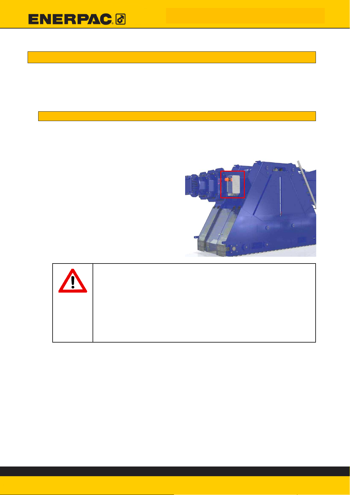
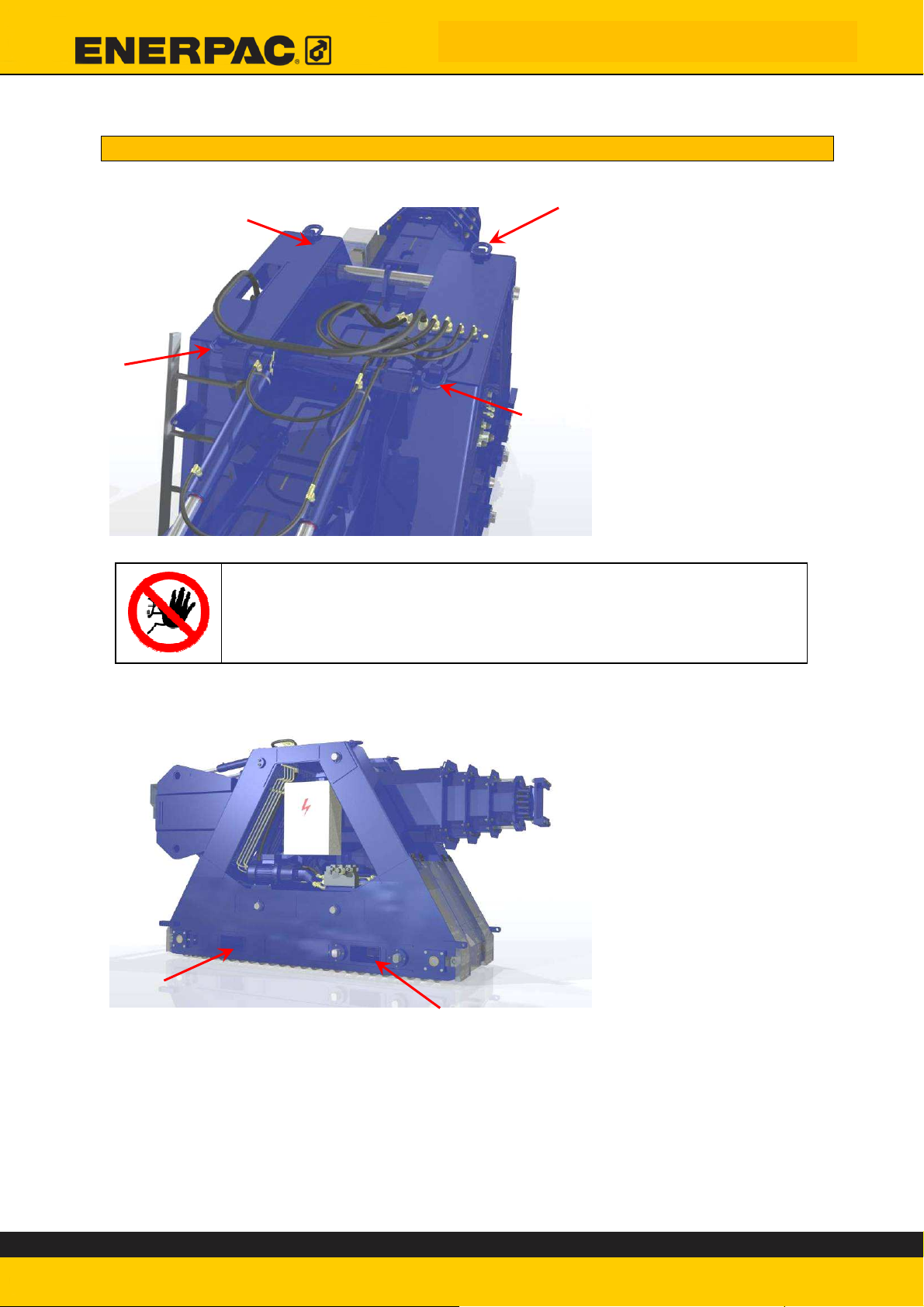
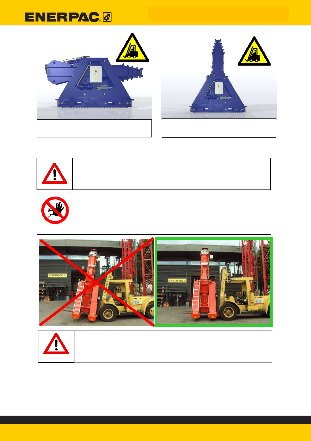
4.2. Handling
Each unit is fitted with four lifting eyes, as shown in the figure below:
Always use all four of the lifting eyes
The lower section of the base is provided with two lifting openings for a forklift
truck:
Lifting eyes can only be used when the mast is in retracted position (horizontal
position). Use of the forklift trucks is permitted in both positions. Please note that
when using the forklift truck with the mast in extended position, the centre of
gravity (COG) of the unit is considerably higher, and therefore less stable.
ED.02518.00.001.R03.ENG
Page 25
Explanations of Methods
In extended position, only use the fork openings
In this setup, it is possible to use both the lifting
eyes and the fork openings.
In order to prevent damage to the wheels, all movements, in any direction, must
be executed at a height of 300 mm off the ground.
In order to prevent damage to the wheels, all movements, in any
direction, must be executed at a minimum height of 300 mm off
the ground.
• The unit can only be moved if the telescopic cylinder is
fully retracted.
• Movement of the unit is not permitted with the top beams
mounted on the top plates.
for lifting trucks to move the units.
Hold the mast of the lifting truck upright.
Leaning it too far back may cause damage to the roller tracks.
ED.02518.00.001.R03.ENG
Page 26
Explanations of Methods
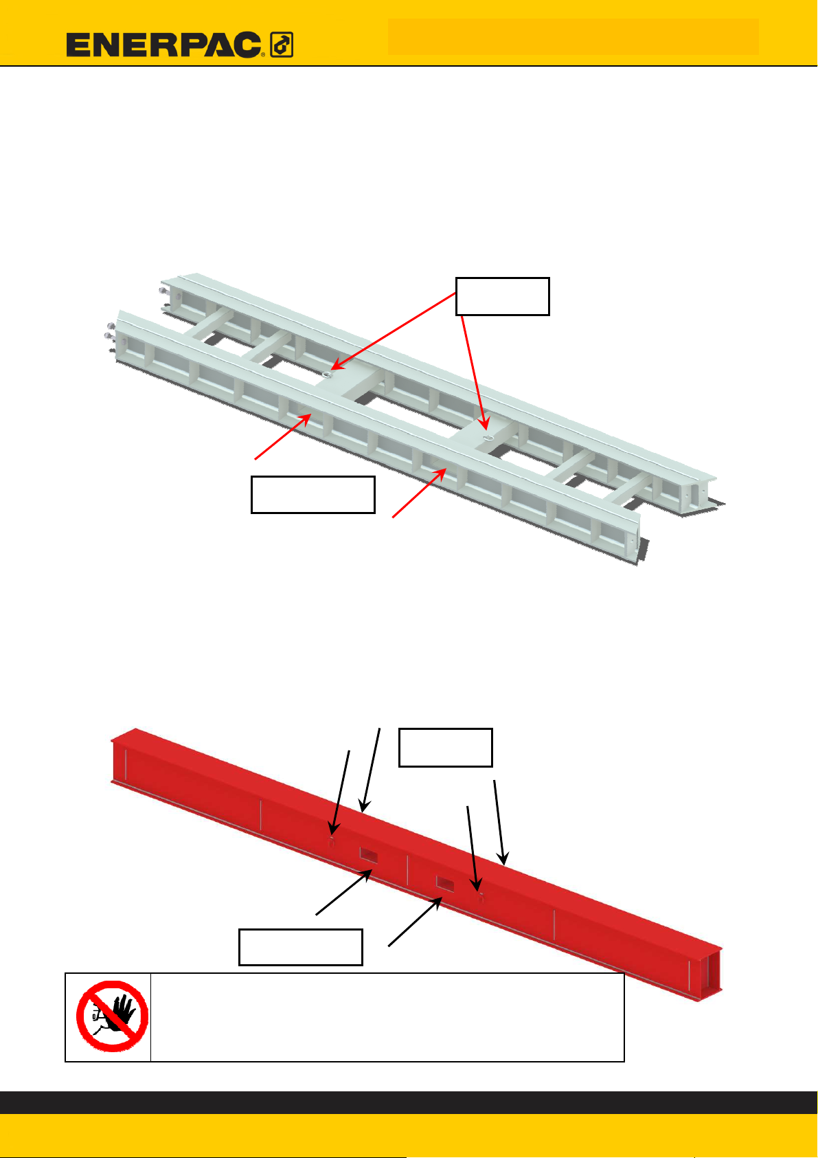
4.2.1. Skid tracks
The skid tracks may be moved in two ways:
1. With a forklift truck. For this, the skid tracks are fitted with fork holes
2. Using a crane. For this, the skid tracks are fitted with 2 lifting eyes.
See illustration below:
Lifting
Fork holes
4.2.2. Header beam
The header beams may be moved in two ways:
1. With a forklift truck; the header beam is provided with fork openings for
this
2. Using a crane; for this, the header beam is provided with four lifting eyes.
See illustration below:
Lifting
Fork holes
Always use all four lifting eyes
ED.02518.00.001.R03.ENG
Page 27

Explanations of Methods
4.2.3. Side shift
The side shift may only be moved using the lifting eyes. Once the side shift is off
the beam, it must be laid down flat as shown in the illustration below:
In order to place the side shift on the beam, it is
provided with lifting eyes.
During assembly, always work with two or three
lifting chains; in this way the side shift always
remains horizontal during lifting. See
illustration:
In this case, set a filling
block for lifting.
Always set a filling block between the roller bearings first before
raising the side shift.
This is to prevent damage to the shift shift motor.
ED.02518.00.001.R03.ENG
Page 28

Explanations of Methods
4.3. Placement of the skid tracks
In order to ensure proper functioning, the system should be set up level on the
ground. In many cases, the subsoil is not flat and must be graded to create a
good solid foundation on which the system can work safely.
The definition of a good supporting surface is:
a properly graded base that cannot be deformed by transverse forces under load
or overloading.
Guide rails have two functions:
• The use of guide rails reduces the basic loading
• They guide the portal lift over their length, so that the possible danger of
misalignment is avoided.
Creating a proper foundation must be handled with the utmost of
care, as it is the system's primary safety issue.
Failure to use the guide rails
may result in improper
alignment.
Unstable surfaces cause instability.
Concrete is not a suitable
foundation for wheels.
4.3.1. Requirements for the skid tracks
Permissible skid tracks are:
1. The skid tracks manufactured by Enerpac, supplied with the machine.
2. Additional skid tracks supplied by Enerpac.
3. Skid tracks that comply with the following requirements:
a. Prescribed material and the dimensional tolerances specified on the
drawing in Appendix F and in Chapter 4.3.2.
b. The materials used must be accompanied by materials certificates
type 3.1.B.
c. The skid track must be tested statically before use to an overloading
of 125% of the maximum capacity; during this a notified body must
have been present. The said notified body must issue a certificate
for this.
d. At an overloading of 125%, the stresses in the material must remain
below 60% of the yield point.
e. All welding work must be executed according to EN-ISO 15614-1.
f. The quality of the welding processes must comply with EN729.
g. The welding must be approved and in this comply with EN-ISO 5817
class B.
Check of the skid tracks before use
ED.02518.00.001.R03.ENG
Page 29

Explanations of Methods
4.3.2. Check the skid tracks for damage before installation.
Several minimum requirements are listed below.
Pay special attention to the welds:
Pay special attention to the welds. There should be no fissures in them.
Enerpac can provide you with skid tracks: the wide range of
available lengths is listed in appendix G.
These skid tracks are hot-dip galvanized and meet all of
Enerpac's requirements for skid tracks.
The flatness tolerance of the running
surface is 5 mm over 3 m (1/5” over
10’).
The rails may not be skewed in side
view. The angle from the horizontal
plane must be less than 0.2° in both
axes.
°
2
,
0
0
,
2
°
0
,
2
°
°
2
,
0
The incline angle of the running surface
must not be more than 0.2°.
Never use rails which do not meet the above requirements.
4.3.3. Requirements for the filler material
The filler material must be stacked contiguously so that there is no
risk of spring action!
Minor deformations in filler material or subsoil may result in strong
internal transverse forces or diagonal or longitudinal movements of
the load or masts.
ED.02518.00.001.R03.ENG
Page 30

r
Permitted filler materials:
1. Hard wood with a mechanical compressive strength of at least
25 N/mm² without occurrence of deflection
However, Enerpac strongly recommends adhering to
30N/mm². Preferably Azobe.
The minimum hard wood thickness is 50 mm and the
maximum thickness is 150 mm.
NOTE:
Use of other wood types such as plywood, multiply, pine
and compressed wood is expressly prohibited.
Wood is a natural product, which means its quality is not standardly
assured. In order to guarantee quality an appropriate test must
be conducted before use to verify that the material meets the set
requirements.
2. Steel filler plates, provided they are properly secured with a
mechanical compressive strength of at least 30 N/mm²
without occurrence of deflection.
Use of other materials is not permitted!
In case of doubt, consult Enerpac
For your planning, please bear in mind that the ideal wood is not
only hard to the touch; it is also hard to acquire.
Explanations of Methods
4.3.4. Placement of the filler material
If it has become apparent from Chapters 3.4 and 3.5 that it is necessary to install
filler material under the skid tracks, this must be implemented as prescribed in
Chapter 3.5.
The parameters L, H, B and S are listed in the checklist in Appendix A.
When laying the filler material, always consult with the person
who performed the calculation in section 3.5.
This is necessary to prevent excessive surface loading.
ED.02518.00.001.R03.ENG
Page 31

Explanations of Methods
Standard geometrical requirements for the filler material:
Parameter Requirements
L > L Min. (to 914mm)
M > M Min.
B > H and > 250mm
S < 250 mm
1. Install the filler material as determined by the preparer.
Pay attention in this to the following points:
Filler material must be laid with the largest surface on the horizontal
zone.
Track couplings must always be fully supported.
ED.02518.00.001.R03.ENG
Page 32

Always put filler material under the ribs in the skid track!!
Explanations of Methods
Always place a steel plate with
a minimum thickness of 15 mm
between the skid track and the
filler material at the joint.
At least 150 mm of each skid
track must be on the steel
plate.
Steel plate width at least 300
mm + 2x the thickness of the
plate
2. Next, place the skid tracks on the filler material.
3. Align the guide rails
4. Ensure that the rails run parallel to each other:
A maximum deviation of ½’’ (~12 mm) in the alignment is permissible:
ED.02518.00.001.R03.ENG
Page 33

Explanations of Methods
5. Ensure that no clearance is left between the filler material and skid
tracks.
Before the units are placed on the skid tracks, these must comply with
the following requirements!
Ensure that no clearance is left between the filler material and
skid tracks.
For filler material requirements, see section 4.3.2.
Enerpac can provide you with additional skid tracks or advise you
on an appropriate design for your application during the planning
phase.
The flatness tolerance of the running
surface is 5 mm over 3 m (1/5” over
10’).
The rails may not be skewed in side
view. The angle from the horizontal
plane must be less than 0.2° in both
axes.
°
2
,
0
0
,
2
°
0
,
2
°
°
2
,
0
The incline angle of the running surface
must not be more than 0.2°.
Ensure that the running surfaces of the
rails are aligned. Otherwise, use shims
to align the surfaces. Ensure that the
angle of incline created is less than
0.2°.
ED.02518.00.001.R03.ENG
Page 34

Check that the skid tracks meet all requirements and
fill this in on the checklist in appendix B.
Explanations of Methods
Connect the rails or plates together
under tension. Gaps between the
surfaces may cause dislocation of the
lifting foot and thus of the load.
ED.02518.00.001.R03.ENG
Page 35

Explanations of Methods
4.4. Placement of the unit
After the rails have been correctly aligned and connected, the lifting feet may be
placed on to the rails. The groove in the wheels must engage with the guide ridge
on the rails.
Check that the units are on the rails properly and
fill this in on the checklist in appendix B.
4.5. Connection of power cable
Once the units are in position, the power cable can be connected. Each unit must
be connected separately to the electricity supply. Connect the power cables to
each of the units’ power connections:
Specification of the power source:
Voltage :360 to 480 V AC/ 3-phase
Current :16 A per unit
Frequency :50-60 Hz
Power :7.5 kW per unit (10 hp)
The units feature automatic phase selection according to the rotation direction of
the electric motors.
Once the power supply has been connected, the masts can be set upright.
ED.02518.00.001.R03.ENG
Page 36

Explanations of Methods
4.6. Erect the mast
Once the rails have been installed, the lifting feet brought into position and the
cables connected, the SBL1100 is ready for use. The masts can now be extended.
Mast extension is a manual operation and is performed on the electrical control
panel of the SBL1100.
Never attempt to extend or retract masts to which something is
attached or which are fitted with a buffer beam. The extension
cylinders are not designed to bear additional weight.
Do not attempt to erect or retract an extended mast. The upright
structure has a very different centre of gravity (COG). This will
damage critical structural components.
Do not extend masts when a person is too close to the masts.
ED.02518.00.001.R03.ENG
Page 37

Explanations of Methods
Remove the three lifting shafts from the frame. To do so, first remove the spring
clips. Pull the shafts out until there is no connection between the mast and the
frame (approximately 80%). The fourth shaft is locked and serves as a point of
rotation. This shaft cannot be removed, except during maintenance.
Check that there is no one within the range of the lifting foot. Check that no
cables are pinched and that there is no load on the masts. Use the switch on the
front panel to extend the masts.
ED.02518.00.001.R03.ENG
Page 38

Explanations of Methods
When the masts are in vertical position, put the shafts into position and lock them
with the spring clips:
After setting and locking all pins, decompress the extension cylinders by retracting
them slightly. Keep an eye on the pressure gauge: there should not be any
pressure buildups.
Always put all three shafts into position. The portal lift is
designed to distribute weight across the shafts. A missing shaft
may result in an unstable foot and thus also an unstable system.
ED.02518.00.001.R03.ENG
Page 39

4.7. Mounting the header beams
In order to mount the header
beams on the units, the six bolts
on the top of the swivel plate
must first be removed. Remove
the locking strips.
Place the header beam on top of
the swivel.
Replace the strips and the six
bolts (M20 St8.8 Elvz.). Adjust
the beams to be level before the
beam is fixed to the lift.
In this way, a fixed connection
between the unit and the beam
is achieved. (For the operation of
the machine, see Chapter 7.)
Tighten the bolts to 370Nm
Always install all six bolts. The header beam may shift slightly,
which will exert a considerable amount of force on the bolts. If all
bolts are not used, the structure may get damaged.
Check that the beam is level and that all bolts are tightened
properly. Fill this in on the checklist in appendix B.
Explanations of Methods
ED.02518.00.001.R03.ENG
Page 40

4.8. Mounting the side shift
Place the side shift on the beam as shown in the
illustration alongside. See section 4.2.4 for how to lift
the side shift.
Place the lifting beam as illustrated
alongside:
Explanations of Methods
Feed the cable through the guide
roller.
Fix the cable into the connector and
attach the strain relief to the eye
provided.
Ensure that the cable is mounted in such a way that it cannot get
pinched.
Fit the locking strip as shown in the
illustration next to this text. Tighten the bolts
(M12) to
60 Nm.
Check that the side shift is on the beam properly and that the lifting
beam is set and locked. Fill this in on the checklist in appendix B.
ED.02518.00.001.R03.ENG
Page 41

Before raising the load
5. Before raising the load
Before using the portal lift, certain matters must be checked.
1) Check whether the checklist in Appendix B has been fully completed and
signed.
2) Carry out a visual inspection of all lifting feet. Assure yourself that there are
no signs of excessive rust and that no parts of the portal lift are damaged.
Rust means a weaker structure.
3) Carry out a visual inspection of all hydraulic components.
Assure yourself that there are no signs of wear or damage.
Oil leakage may indicate wear or damage to the system.
4) Define what is known as a defined drop zone. This is the area outside of
which you and all bystanders and goods on the site are safe, if anything
should go wrong. Cordon off this area using barriers, tape etc., in such a
way that no one can enter the area.
5) Ensure that the running surfaces of the skid tracks are clean and that the
unit cannot slip or be obstructed.
6) Check whether all wedges have been removed from the rams.
See Chapter 7.4.
7) Slide all masts in and out a little to check that all communication functions
are working properly.
8) Drive the units forwards and backwards a short distance.
9) If applicable, do the same for the Side Shift units.
10) Check whether the correct load is indicated. This is of course the
weight of the beams and the internal resistance of the feet themselves. The
load must only be raised after all preparatory measures have been
implemented and the system is fully ready for use.
Always check the points given in this section before beginning to
move with a load.
ED.02518.00.001.R03.ENG
Page 42

Before raising the load
11) Check before raising loads that the load anchorages are in line with
the fixing points on the load:
Use a plumb line, a laser, or a theodolite.
If the anchors are not in line with the fixing point, the load will start to sway as
soon as it comes off the ground. This causes a huge transverse load on the
portal lift, and might even lead to the portal lift tipping over. Such accidents
have happened in the past, and were attributable to carelessness on the part
of the operators.
12) Always keep lifting straps as short as possible. With long lifting
strops, the load will always have the tendency to start swinging during
travelling or sidewards movement. This can also cause unexpected
sidewards loading of the portal lift:
13) The beam must remain level at all times, with a tolerance of ± 0.2°.
This section is associated with the checklist in appendix C
The load cannot be moved until the checklist in appendix C has been
completed in full and signed.
ED.02518.00.001.R03.ENG
Page 43

Checklists
6. Checklists
The checklists have been drafted to ensure safety before and during the lifting
operation.
The checklists have been prepared in chronological order in order to keep their
completion as simple as possible.
Only once all checklists have been fully completed, and all the requirements in the
checklists have been fulfilled, may the load be raised.
Always have the checklist verified and signed in approval by a second person
authorised by the machine’s owner.
The objective of this is to create extra certainty that the checks have been
correctly executed.
Work exclusively according to the checklists: during preparation
for the lifting operation, system construction, and for lifting the
load.
Failure to adhere to the checklists may result in serious injury to
users and bystanders, and possibly even death.
6.1. Preparation for a lifting operation
The checklist for preparation may be found in Appendix A.
Make a copy of the list, or print one out from the CD-ROM supplied.
The checklist during preparation is to check:
• The machine is able to carry the load.
• The foundation can carry the load.
• To establish how high the wind speed may be during the operation.
Various pieces of information that are important during setting up the machine are
entered in this list during the work preparation.
It is therefore important that this list is continuously available during setting up
the machine.
It is only permitted to start setting up the machine once the checklist is fully
completed and if all the requirements stated in this manual are fulfilled.
ED.02518.00.001.R03.ENG
Page 44

Checklists
6.2. Setting up the portal system
The checklist for erection is to be found in Appendix B.
Make a copy of the list, or print one out from the CD-ROM supplied.
The checklist during erecting the machine is to check:
• The machine is erected according to the directions in the manual.
• The machine is erected according to the data upon which the calculations
during preparation were based (Appendix A).
This checklist has been drafted in chronological order. Therefore, it is
necessary to go through this list point-by-point from top to bottom. During
checking, as well as during construction.
If it is necessary to use lifting strops, chains or other accessories, this should
also be noted on the checklist.
6.3. Before raising the load
The checklist for during lifting is to be found in Appendix C.
Make a copy of the list, or print one out from the CD-ROM supplied.
The checklist for raising the load serves to check that:
• The machine is not damaged and shows no signs of wear
• The machine’s functions are correct and all work in the right direction
• That the machine is correctly situated above the load.
This list must be completed by the operator of the machine during the lift
operation.
ED.02518.00.001.R03.ENG
Page 45

Working with the machine
7. The operation of the machine
The portal lift may be used in two ways:
• Manual operation, known as “local control”.
• Using the Intellilift, known as “Remote control”.
Once the header beams have been installed on the units, the machine may only
be operated using the Intellilift control panel.
Manual control should only be used during installation.
Before the machine can be operated, the user must read and
understand the manual in its entirety.
In case of doubt, consult Enerpac.
Local control us only permitted if there is a beam attached to the
unit.
A unit is only part of the central emergency stop system if the
control selector switch is in the remote position.
ED.02518.00.001.R03.ENG
Page 46

controller is
controller is not
active
the lifting cylinder
remote control
7.1. The control panel on the unit
Local control of the
travel motors and
Switches to tilt the
mast
Move side shift to
the left and right
Switch to equalize
the travel direction
Working with the machine
Switching voltage
present
Motor for hydraulic
pump running
Frequency
Switch to equalize
the side shift
direction
Speed selection for
local control
Toggle switch
between local and
Button to switch
unit on/off
Frequency
Side shift overload
protection signal
Emergency switch
NOTE: this only
works on other
units if they also
work on remote
control
Emergency stop
signal active.
An emergency stop
switch is active or
there is no
connection with the
Intellilift panel.
ED.02518.00.001.R03.ENG
Main power switch
Page 47

The direction of the side shift and travel depends on the “travel
direction” and “side shift direction” selector switches
Before the shaft between the side shift units is coupled, the direction
of the side shifts must be checked.
Working with the machine
ED.02518.00.001.R03.ENG
Page 48

The RS845 connection. Connection
Display. Displays basic
Emergency stop switch. When activated,
Fast/slow
rse
7.2. The Intellilift control panel
Working with the machine
information, such as load per
lifting foot, lifting height per
foot, and messages
Cylinder
selection.
Activates and
deactivates
individual lifting
feet. Useful
for fixed wiring. This connection is
also used to charge the batteries.
power is cut to all power cables.
They must be reactivated manually for each
lift component.
Power
Lift
Lift/lower
Travel
Forward/reve
Side shift
Left/right
Zero lift switch. Resets the
lift counters of the
activated lifting feet to 0.
Always select "tortoise mode" on the speed selector switch when
working with a load on the machine.
Only one function can be active at a time!
ED.02518.00.001.R03.ENG
Page 49

Working with the machine
7.3. Manual control
Local control is useful during assembly of the machine. It may be used to put the
separate units into the correct position.
During local control, no detection of the load or hysteresis takes place. In other
words: manual control is unsafe control, and must only be used during installation
of the units and as long as no beams have been mounted on the units.
This is how you work with a unit manually:
1. Ensure that the main switch on the control panel of the unit in question is
set to 'on'.
2. In order to raise a lifting foot manually, the control switch on the unit
should be set to ‘local’.
3. Switch the unit on using the operation switch on the unit’s control panel.
4. The desired speed can be selected using the speed selection switch on the
control panel.
5. The following functions may be controlled via the control panel on the unit:
a. The ram can be extended and retracted.
b. The unit can be made to travel.
c. The mast can be tilted.
d. The side shift can be controlled.
Important: only for maintenance purposes.
7.4. Intellilift control
7.4.1. About Intellilift
The Intellilift control system has been developed to allow loads to be raised and
lowered under control.
The control system ensures that the units remain within a hysteresis of 24mm.
For this, it is necessary that the Intellilift is set up correctly.
See section 7.4.3.2
The emergency stop system will not work if the control valves are
not calibrated by Intellilift.
7.4.2. Communication
7.4.2.1. Cordless
Intellilift uses cordless communication. This means that
communication with the lifting units takes place via radio
waves.
The frequency of the cordless communication is 2.4 gigahertz.
ED.02518.00.001.R03.ENG
Page 50

Working with the machine
Dongle
7.4.2.2. Data cables
In places where the use of radio waves is not allowed, data cable communication
may be used.
See section 7.4.4.3 for how to switch between cordless and data cable
control.
For a wired connection of the lifting feet, the data cables are connected together
using RS-485 connection, in such a way that the following network arises:
Intellilift control
panel
The use of a network requires a closed circuit. Connect a dongle (terminator) to
the last unit in the circuit.
It is not important which cable is in which connector as long as the circuit is
terminated. The same applies to the dongle. The right- and left-hand connectors
are identical.
Switchbox, nothing
connected.
Switchbox, with connections
from one unit to the next
Connected switchbox, end of
the ring network.
Dongle
7.4.3. Normal operation
1. Switch the Intellilift control panel on by setting the “power” switch to “on”.
2. The Intellilift control panel will now start up; during start-up, the software
version number is displayed.
3. Before using, check that the control panel battery is fully charged.
This is to prevent problems due to a flat battery during the lifting operation.
A full battery has a capacity of around 8 hours.
ED.02518.00.001.R03.ENG
Page 51

Working with the machine
See section 7.4.7 for charging the battery.
(full battery on the display)
4. Ensure that the “Emergency stop” button on the Intellilift control panel is in
the non-activated position.
5. Switch the main power switches on the control panels on the units to “on”.
If the power supply is in order, the “power on” indicator on the control
panel of the unit in question will light up green.
6. Ensure that the “Emergency stop” buttons on the units’ control panels are in
the non-activated position.
7. Switch the local/remote selector switches on the units’ control panels to the
‘rem.’ position.
The “emergency active” indicator on the control panel of the unit in question
will light up blue.
8. Switch the “RAM SELECT” switches of the units you wish to operate to the
“on” position.
The units required can now be detected by the Intellilift control panel. If the
connection is in order, the “emergency active” indicator on the control panel
of the unit in question will go out.
9. As soon as the “emergency active” indicator has gone out, the unit can be
activated.
10.It is now possible to use the following functions: Lift, Travel, and Side shift.
A unit may be deactivated temporarily using the ram selection switches.
Only one function can be operated at a time.
Level indicator
7.4.3.1. Lift
If you want to start lifting or lowering, first check the values indicated on the lift
counter on the display.
Remember that the control unit keeps the lifting height of all units selected using
“ram select” within a hysteresis of 24 mm.
You can reset the values on the lift counter using the ZERO LIFT button.
By pressing this button, the current, absolute position is set as start point, so that
all lift counters indicate zero.
When you start the lifting or lowering action, the unit stops a ram as soon as the
lifting position exceeds the range by too much (more than the hysteresis of
20 mm).
ED.02518.00.001.R03.ENG
Page 52

Working with the machine
Once the position is back to within half of the hysteresis, the movement is
restarted.
Besides this, you may during lifting put the ‘speed’ switch into the “hare” position
to increase the speed while working without load.
Whenever one single ram is extended too far in comparison with the others (more
than half of the hysteresis), the movement is slowed until all the other rams are
within a quarter of the hysteresis range.
After repositioning the skid tracks, the beams must be levelled.
After this, give the zero lift command.
Always select "tortoise" mode on the "speed" selector switch
when working with a load on the machine.
7.4.3.2. Travel
The SBL system is a self-driven system. Each unit is provided with two
hydraulically-driven travel motors. These motors are connected via chains to the
roller tracks under the frames.
If the direction of one or more units does not match, this can be changed using
the “direction travel” selector switch on the control panel of the relevant unit.
Only use the "travel direction" selector switch after the machine
has come to a complete standstill.
Travel motor
Roller track
Travel motor
The synchronous travel of the four SBL units is realised using what are known as
pulse counters that are fitted on the output shaft of the travel motors:
ED.02518.00.001.R03.ENG
Page 53

Working with the machine
Pulse
Pulse gear
The pulses from each SBL unit are counted by the Intellilift remote control unit.
Whenever, on one unit, four pulses more than on the other three units are
counted, the drive to the unit concerned is briefly interrupted, until four more
pulses are added for the other three units. Then, the stopped SBL unit continues
travelling.
This four-pulse discrepancy is equivalent to a 15.4 mm difference in distance for
the SBL units. In other words, the maximum discrepancy between the four units is
15.4 mm. This is a standard setting that cannot be changed.
You may during travelling put the ‘speed’ switch into the “hare” position to
increase the speed while working without load.
Always select "tortoise" mode on the speed selector switch when
working with a load on the machine.
Every time the travel function is used, the synchronization is
reset.
Therefore, use this function until the lift is in the desired position.
If the machine comes to a complete standstill during travel:
check that there is nothing blocking the unit.
Position the individual units correctly before travelling further
with multiple units.
ED.02518.00.001.R03.ENG
Page 54

Working with the machine
7.4.3.3. Side shift
Each side shift is provided with an electrical drive. This drive has a single speed.
There is no equal-travel regulation, although the drive roller is provided with
knurling for sufficient traction on the beam. The side shifts on the same beam can
be coupled together mechanically with a coupling rod.
If the direction of one or more side shifts does not match, this can be changed
using the “side shift direction” selector switch on the control panel of the relevant
unit(s).
7.4.4. LCD screen
The LCD screen is provided with background lighting.
In order to extend the battery life, the background lighting is switched off if no
changes are detected for a period of 15 seconds.
Only use the "side shift direction" selector switch after the
machine has come to a complete standstill.
7.4.4.1. Level indicator
The following values are displayed on the screen:
• The total load on the selected units: “Tot”
• The absolute “position” for each unit
• The “lift” position with respect to the zero lift position
• The “load” on each unit
You can read the load on each selected cylinder separately from the control panel.
The values indicated for the non-selected cylinders are invalid! The load indicated
is calculated using the value from the pressure sensor and the ram range. Given
that the cylinder has multiple stages, the conversion factor changes from stage to
stage. Enerpac has configured the position where the factor change ought to take
place. Small errors in the position indication may cause a ‘jump’ in the load
indication at a switch point.
If an incorrect factor is used on the second or third stage, then an overload
message may be displayed. There is however no actual physical overload! This
can be resolved by recalibrating the position measurement, or by slightly reducing
the switchover point (please contact Enerpac for this).
Due to the nature of the hydraulic system, the load value is only
valid in static situations!
ED.02518.00.001.R03.ENG
Page 55

Working with the machine
7.4.4.2. Overload warning
If the calculated load is above the maximum value, an asterisk appears before and
after the load value (*900*).
Once this indication appears, it is not possible to extend the unit in question any
further.
7.4.4.3. Communication timeout
When it becomes difficult to communicate with a certain unit, a message like this
appears: Communication-time-out.
Try moving to a different position – this usually helps. (The fault may be caused
by reflections in areas known as reception dead areas.) Also check that the unit in
question is still receiving power.
Switching to data cable control (RS485 mode)
If you experience many problems in cordless mode, as a result of external
influences or a fault, you may use wired mode.
• Switch off the Intellilift control panel and the main power switches on the
units.
• Connect the communications cable between the Intellilift panel and the
units.
o First switch all units on according to steps 5 to 8
in section 7.4.3.
• Switch on the Intellilift panel with all selection switches in the OFF position;
if communication is working properly, a star will be displayed after the lift
value – see illustration
• The LCD display indicates that the control has been switched to wired and
the cordless control is deactivated until you switch the control panel off and
back on again (without cables connected).
ED.02518.00.001.R03.ENG
Page 56

Working with the machine
7.4.5. Emergency stop system
If the emergency stop button on the control panel is pressed, the message
“***Emergency pressed***” appears on the display.
This message also appears when the emergency stop button on one of the units is
pressed, but only if that unit's cylinder was selected!
The display also shows which unit caused the emergency switch-off.
In such cases, the main motors for all cylinders are stopped.
The system may be started up again by going through steps 6 to 8 in section
7.4.3.
7.4.6. Switching off the control panel
When the control panel is switched off, you can no longer control the units.
If the units receive no signals for 2 seconds, all outputs switch to a stand-by
condition.
If the ram receives no messages for 10 seconds, the main motor is also switched
off.
After the connection is restored, the system may be started up again by going
through steps 6 to 8 in section 7.4.3.
If the control panel is switched off during an emergency situation, the main power
supply to all units must be switched off for at least 20 seconds before the system
can be restarted.
7.4.7. Charging the battery
There is a lithium ion battery in the control unit. The battery has a capacity of
around 8 hours in normal operating mode. In order to extend the battery life, the
background lighting is switched off if no changes are detected for a period of
15 seconds.
After completing a lifting operation, connect the charger to the control panel (set
the power switch to the OFF position). The display shows the current battery level
and charging status. A fully charged battery should read 8.4 V. The charger feeds
the circuit a controlled 12.0V power supply.
Do not use any other voltage levels, as this may damage the
circuit!
Do not charge the battery at temperatures below 0ºC (32º
Fahrenheit) or above 45ºC.
Only use the adapter provided with the equipment to charge the
batteries.
ED.02518.00.001.R03.ENG
Page 57

Working with the machine
7.4.8. Settings
7.4.8.1. Learning a replacement Intellilift control panel
Each control panel has a unique code. In order to make control possible, you must
match the separate receivers with the control panel. This has usually already been
done by the programmers at Enerpac. But in the case of a serious fault, it may be
necessary to reprogram the panel. This is also true when the old panel is replaced
with a new one. The matching remains valid, even after switching off the power.
Steps to reprogram the panel:
1. Check that the battery is fully charged
2. Switch off all ram selection switches on the control panel
3. Switch on the control panel
4. Switch on the unit to be ‘matched’
5. Put the RAM SELECT SWITCH 1 (on the control panel) to ON
6. On cylinder 1, press and hold the ‘LEARN’ button for about half a second
(and then release it)
7. As soon as the NO ANSWER message disappears, set the RAM SELECT
SWITCH back to OFF
8. Repeat steps 5 to 7 for cylinders 2, 3 and 4
If the control panel is switched on first, then the system will start
up faster during power up.
Always ensure that you match RAM 1 with selection switch 1, given that the
settings are individually calibrated!
ED.02518.00.001.R03.ENG
Page 58

Working with the machine
7.4.8.2. Recalibration procedure
This subsection describes how to reset the masts to zero position:
Step 1: Set all cylinders to the minimum position
Step 2: Deselect all cylinders
Step 3: Switch off the power supply to the remote control unit
Step 4: Switch the “Speed switch” to the ‘hare’ symbol (high speed)
and press the “Zero lift” button.
Step 5: Keep the “Zero lift” button pressed and switch on the power
supply to the remote control.
Step 6: Keep the “Zero lift” button pressed until the message “System
not ready” appears on the remote control unit display
ED.02518.00.001.R03.ENG
Page 59

Working with the machine
Step 7: Release the “Zero lift” button and the “Calibration mode”
message will appear on the display
Step 8: Now select the cylinder you wish to calibrate, wait for about 5
seconds and then deselect the cylinder.
Step 9: Thereafter the power supply to the remote control unit should
be switched off. The cylinder position is now calibrated and the position on
the display is around 0 mm
If the calibration proceeded successfully, this message appears:
“Calibration succeeded”.
If there was poor communication during the calibration, causing it to fail,
the following message appears:
”Calibration failure”.
ED.02518.00.001.R03.ENG
Page 60

Working with the machine
communication timeout to
7.4.9. Correction of faults
Here you find a short list of possible faults, their causes and solutions:
Symptom
Load value –300 (large
negative value)
Large negative position
value
All units selected, but
none move up
All units selected, but
only one moves up
After switching on the
control panel, it will take
a moment for the
disappear.
No display indication after
switching on the control
unit
Communication problems
when you place your
hand on the top right
corner of the control
panel
Possible cause
Faulty wiring or loose
connector on the LED
indicator
Faulty wiring, loose
sensor wire
Possible solution
Check the wiring,
measure the current
(should be 4 - 20mA)
Check the position
reading for the physical
cable, check the position
sensor
One of the main motors
has stopped, is outside of
Press the START button
to restart the motor
the lifting hysteresis
Lifting value was not
reset, only the unit with
the lowest lifting value
moved up
This is normal – the
receivers continuously
First reset the lift
counters (even if you
have switched off the
control panel)
Wait approximately 30
seconds
scan the various RF
channels when they
cannot find a control unit
Battery is low Charge the battery for at
least 4 hours
This is where the internal
aerials are located.
Do not place your hands
on this area.
ED.02518.00.001.R03.ENG
Page 61

Working with the machine
7.5. Mechanical locking
The SBL1100 is provided with a mechanical locking system. This system may only
be used when the portal lift is under load and must remain in this position for a
longer period.
The system is based on a wedge-locking system that is mounted on both sides
and on each phase of the mast.
The system must be controlled manually, and can only be unlocked by means of
an extra extension stroke. It is therefore necessary to check in advance whether
such an extra extension stroke is possible, from the position where you want to
activate the mechanical locking. When the cylinders are locked in fully extended
position, the system can no longer be unlocked because the wedges will not
release.
How to do this:
The SBL1100 is provided with a ladder for access to the top of the frame. It is
possible to activate the grips from the landing. These grips serve a safety
function. They provide a mechanical locking system for the booms. The locking
mechanism is controlled by inserting the wedges or by removing them manually.
The wedges can be inserted as shown
here
Here, the wedges are in their correct
position
The grips can only be enabled during a lifting stroke. When the cylinder needs to
be retracted, the grips will have to be disabled or else the grips will take hold and
lock the booms to one another.
To use the grips for locking a load to a certain position, a so-called ‘load-transfer’
will have to take place. During this transfer the load is shifted from the cylinder to
the grips. To make this load transfer the cylinder must make a small retracting
stroke. The load will then be transferred. This also means that when the cylinder
ED.02518.00.001.R03.ENG
Page 62

Working with the machine
has to pick up the load again, it first needs to make a small extending stroke. The
load will then be transferred back to the hydraulic cylinder. Hereafter the wedges
can be disabled again and the cylinder can be retracted.
Keep in mind that the cylinder needs to extend a little to transfer the load from
the wedges to the cylinder. This means that during long-term storage of a load
where the safety grips are used, the cylinder should never reach the end of its
stroke. Always keep an additional distance of 100 mm.
7.5.1. Use of wedges
The wedges serve as a safety precaution when the load has to be supported for a
longer period. Firstly, the load has to be put into the correct position, and only
after this may the wedges be inserted.
During long-term storage of a load, there is always a small risk that the rams leak
a little. If this happens, the wedges take the weight over and prevent the load
dropping.
The wedges must never be inserted during lifting. This is only allowed once the
load is hanging at the correct height and the system is ready to be switched off.
Before the hydraulic portal lift has taken over the full load, removal of the wedges
under load is impossible. Due to the compressibility of the hydraulic oil, the oil
column in the ram is compressed immediately upon transfer of the load to the
portal lift. The compressibility of the oil is around 1% for each 100 bar of pressure
(1450 psi). Thus, when the ram extends to 100” (2540 mm) and the load transfer
occurs on the top of the portal lift, and the resulting pressure is 100 bar, the oil
column is compressed by around 1" (25.4 mm). This means that the height of the
portal lift is also reduced by around 1”, with the result that the wedges receive the
pressure exerted by the load. Only after removal of this load can the wedges be
deactivated.
Normally, the rams are extended at low pressure until the portal lift takes over the
load. The pumps remain in operation and the pressure in the hydraulic system is
built up. This ensures an immediate compression of the oil. Because the pump
remains in operation, this compression process is not noticeable. When the entire
load is taken over by the portal lift, the compression is at its maximum and the
pump pumps compressed oil. It is now easy to deactivate the handles and to
reactivate them.
Never use a full stroke when the safety grips are operational.
Only a slight extension of the cylinder is necessary to transfer
the full load from the grips to the cylinder.
Never use grips before the full load has been taken over by the
hydraulic portal crane.
ED.02518.00.001.R03.ENG
Page 63

8. Special applications
Special applications
8.1. Tilting a load
It is possible to tilt a load with an SBL lift. This is in fact a risky operation, because
incorrect control can lead to sidewards forces arising.
Normally speaking, Enerpac recommends keeping the slings or lifting strops as
short as possible, but when tilting a load, longer slings or lifting strops should be
used. In this way, the sidewards forces are kept to a minimum and the sidewards
resultant force is no longer directly observable.
During tilting, it is only permissible to work with two units.
The units attached to the top of the load in the lain-flat situation (the blue units in
the illustrations) may not be operated during tilting.
Tilting of a load must only happen in the following way:
1. The units which are attached to the top of the load in the lain-flat situation
must be placed in the desired position
2. Thereafter, these units must not be used any more during the tilting of the
load. These units must also not be switched to the neutral setting, if
present. (the blue units)
3. The other two units are now extended a little. Next, travel them a short
distance towards the other units so that the lifting eyes are once again
directly under the header beam. (the red units)
4. This sequence should be repeated until the load has been tilted.
Make small movements of no more than 5 centimetres, both in lifting and
travelling.
Check continuously that the lifting eyes are vertically under the
beam: a tolerance of ±0.2° applies here.
Make use of a plumb line, a laser or a theodolite for this.
5. Now all units should be selected and the command “zero lift” should be
given.
6. The lift can now be operated in the normal way.
Procedures described in this section should only be performed by
experienced operators and only in the manner described in this
section.
Before starting any special applications, contact Enerpac before
hand.
All the other requirements mentioned in this manual continue to
be applicable.
ED.02518.00.001.R03.ENG
Page 64

The slings or lifting straps must remain completely vertical at all
times. If they do not, this will result in lateral forces. These, in
turn, may cause the lift to loose stability.
Special applications
ED.02518.00.001.R03.ENG
Page 65

This page intentionally left blank
Special applications
ED.02518.00.001.R03.ENG
Page 66

Maintenance
9. Maintenance
In order to obtain optimum performance from your machine and to safeguard the
safety of the users, it is important that your machine remains in good condition.
In order to achieve this, it is strongly recommended to remove dirt from the
machine after every lifting operation, and to check the machine for damage.
Pay special attention here to the hydraulic and electrical components.
Remember that maintenance must only be carried out by skilled personnel.
Damage to components, particularly the rams, can have serious consequences.
Hydraulic fluid safety information sheet, see Appendix I
Maintenance should only be performed by qualified personnel.
Only perform maintenance on the SBL units if they are not under
load and if all lifting beams have been removed.
Any maintenance procedures not detailed in this section can only
be performed by or in consultation with Enerpac.
Periodic maintenance intervals:
Interval Description Product Volume
Every 50 hours,
and at least
once every 6
months
Every 50 hours,
and at least
once every 6
months
Every 50 hours,
and at least
once every 6
months
Every 50 hours,
and at least
once every 6
months
Once every 5
years*
Every year Inspection of the
Lubricate swivel, 4
nipples per unit
Lubricate side shift
8 nipples per unit
Kroon Oil multi purpose
grease 3
Kroon Oil multi purpose
grease 3
+chain
Lubricate guide Shell ultragel 2
Adjust guide
Replace Oil filter +
Refresh or change oil
Shell Tellus T32 or Shell
Tellus Artic
roller chain
10 strokes
nipple
5 drops per
nipple
410 litres
ED.02518.00.001.R03.ENG
Page 67

Maintenance
* For normal use. If in doubt, contact Enerpac.
9.1. Lubrication Points
9.1.1. The swivel
There are four lubrication points on the swivel. These must be supplied with 10
strokes of Kroon Oil multi-purpose grease 3 every 50 lifting hours, or at least once
a year.
9.1.2. Side shift
The side shift is fitted with 4 grease nipples per unit.
These must be supplied with 5 strokes of Kroon Oil multi-purpose grease 3 every
25 lifting hours, or at least once a year.
ED.02518.00.001.R03.ENG
Page 68

Maintenance
Oil level indicator
indicator
cap
filter
Ball valve suction
port
Oil level indicator
The chain in the drive must be lubricated with Kroon Oil multi-purpose grease 3 at
the same intervals.
9.2. Maintenance of the hydraulic system
Once every 2 years, or once a year for intensive use, the oil in the sump should be
changed completely and replaced with fresh oil, or alternatively a purity test
should be performed. The minimum requirement is that the purity of the medium
is in accordance with class 7 of NAS 1638.
9.2.1. Draining Oil
Ensure that the ram is completely retracted.
When changing the oil, use the large ball valve on the side of the sump to drain it.
Remove the filler cap while draining the oil to allow air to flow into the tank. Keep
an eye on the oil level indicator.
If the oil is below the level, then the power supply must be
disconnected.
Now remove the strip that holds the
oil sump in the frame. Remove the
sump from the frame on the forks
of the forklift truck or similar
machine.
There are two caps on the tank
cover, one fill/bleed cap and
one return filter. The fill/bleed
filters filter the air that is drawn
into the sump when the oil flows out of the tank. The used oil can now be drained
through the ball valve. Dispose of the oil responsibly.
ED.02518.00.001.R03.ENG
Fill/bleed
Return
Return
Contamination
Page 69

Maintenance
9.2.2. Filling with oil
The sump can be filled using the fill/bleed opening. Ensure that the ball valve is
tightly fitted on the bottom of the tank, thus avoiding leaks.
Fill the tank up via the filling cap on the top until the oil level is 50 mm below the
top of the tank.
This only applies if a cylinder is fully retracted.
9.2.3. Return filter
The return filter filters the oil that flows back into the reservoir from the whole
system. The filter will become blocked over time (depending on oil usage) and the
oil will cease to be filtered. Keep an eye on the filter’s contamination indicator.
If the indicator is within the green zone, the filter is working correctly. If the
indicator is within the yellow zone, the filter is still working, but must be replaced
as soon as possible. If the indicator is in the red zone, the oil is no longer being
filtered. Replace the filter element immediately. To do this, unscrew the return
filter cap. The internal filter element can now be removed. Replace the element
only with one of the same brand and type, so that correct operation is ensured.
The portal lift uses Hydac return filters, type see the parts list provided with the
machine
Replace the filter every year in any case.
Immediately replace filter element
Over 3 bar
Replace ASAP
2-3 bar
Normal operation
0-2 bar
Do not use other filter elements, with the exception of previously
installed elements.
ED.02518.00.001.R03.ENG
Page 70

Maintenance
After maintenance, put the sump back in its frame. Check that it is secure by
screwing the strip back into position. Reattach the hoses, open the ball valves,
and, if necessary, fill the oil sump.
Before you use the portal lift, make certain that the system is free of air and oil by
pumping oil through the system for several minutes.
When refreshing oil, use the fill/bleed opening to top the oil up. The sump has a
capacity of 410 litres.
See Appendix D for the applicable Material Safety Data Sheet.
Do not use other filter elements, with the exception of previously
installed elements.
ED.02518.00.001.R03.ENG
Page 71

Appendices
Allen key 12
4 wedges
A
B
C
1 2
4
3
9.3. Adjust guides
Every 50 hours, at least once a year in any case, the ram guides must be
adjusted.
9.3.1. Requisites
Torque wrench with 12mm allen
9.3.2. Adjustment
Ensure that the lift is standing on a flat, level surface ±0.2°.
The lift is fully extended during adjustment. Therefore, make certain that you are
in an adequate workspace.
Adjustment is carried out for each stage. Each stage has adjustment bolts for this.
The adjustment order is important. The numbering is given in the illustration
below. The order is explained in the table.
ED.02518.00.001.R03.ENG
It is not permitted to operate the lift on the platform or when
people are present on the platform.
Page 72

Appendices
1A
3A
1A
2A
1. Ensure that the lift is completely retracted.
2. Loosen all 12 adjustment bolts on the painted ram by half a turn.
A
Turn Adjustment Bolt 1A manually with an allen key
until resistance is felt.
Certainly do not turn any further!
B
C
D
Now tighten bolt 3A to 40 N*m
Now tighten bolt 1A to 40 N*m
Turn Adjustment Bolt 2A manually with an allen key
until resistance is felt.
Certainly do not turn any further!
ED.02518.00.001.R03.ENG
Page 73

Appendices
4A
2A
E
Now tighten bolt 4A to 40 N*m
F
G
H
Now tighten bolt 2A to 40N*m
Repeat steps A to F for adjustment bolts B1, B3, B2 and
B4, following the same order as in steps A to F.
Repeat steps A to F for adjustment bolts C1, C3, C2 and
C4, following the same order as in steps A to F.
I
ED.02518.00.001.R03.ENG
The guide in the painted ram
has now been adjusted. Next
extend the lift until the guide
bolts in the second stage are
accessible.
Page 74

Appendices
J
Now the wedges must be inserted so that the second
stage cannot be retracted any further. Always insert
all four wedges.
Then the lift must be retracted by a further metre; as
the wedges are inserted in the second stage, the first
stage will retract.
Next the guide in the second stage must be adjusted
(see illustration for step I) according to steps A to H.
K
The lift must now be extended by a couple of
centimetres, so that the wedges are unloaded and may
be removed.
Important: only remove the wedges after the
second stage has been extended a little. It is
possible that the first stage extends first.
After the wedges have been removed, the lift must be
extended further until the bolts for the third stage guide
become accessible.
Now, the wedges must be inserted so that the third
stage cannot be retracted any further.
Always insert all four wedges.
Then the lift must be retracted by a further metre; as
the wedges are inserted in the third stage, the second
stage will retract.
Now, the guide in the third stage must be adjusted (see
illustration at step I) according to steps A to H.
The tightening torque is 20 N*m this time rather
than 40 N*m
L The lift must now be extended by a couple of
centimetres, so that the wedges are unloaded and may
be removed.
Important: only remove the wedges after the
third stage has been extended a little. It is
possible that the first and/or third stage will
extend first.
M This unit has now been adjusted. Next the rams must be lubricated according
to the section “Lubricating rams”.
This sequence must be followed for all units.
ED.02518.00.001.R03.ENG
Page 75

Appendices
9.4. Lubricating the rams
Every 50 hours, but in any case at least every six months, the rams must be
lubricated with Shell Ultragel 2.
It is not permitted to operate the lift on the platform or when
people are present on the platform.
Before new grease may be applied to the guide,
the old grease must be removed:
First remove the old grease.
for example with a filling knife.
Make certain that no grease residue falls into the
guide.
Once all remaining grease has been removed,
degrease the ram with cleaning spirit.
The fluid may be applied for example using a spray
bottle.
ED.02518.00.001.R03.ENG
Page 76

Appendices
Once the grease residue has been dissolved in
the solvent, the rams must be polished dry.
Use a lint-free cloth.
Once the rams are clean, fresh grease can be
applied.
The grease may be applied for example with a
paintbrush. Ensure that the grease layer is applied
over the whole surface.
ED.02518.00.001.R03.ENG
Page 77

Appendices
9.5. Roller Chain
The SBL1100 is moves on a roller chain.
In normal use a yearly inspection of the chain tension is sufficient
The SBL1100 unit must be lifted for
inspection of the roller chain tension.
This is possible with a forklift or crane.
See section “handeling” for more
information and tips.
During the adjustment, you are under a lifted machine, so use
only lawful hoisting and lifting equipment.
When the SBL's 1100 unit is lifted, the tension of the roller chain can be read
based on the level of bending of the chain under the machine.
When the distance between the top of the middle roller and the frame is more
than 10mm the chain must be tensioned
ED.02518.00.001.R03.ENG
Max 10mm
Page 78

Appendices
1
1
2
1
1
For tensioning the chain, the end bearings must be transferred
The bolts 1 (M16 St8.8 Elvz ) (8x per side)must be unscrewed.
Now the chain can shall be tightened by tightening the bolts 2.
Tighten the chain on both sides evenly until the top of the middle roll is flush with
the plate edge (See below)
Now the bolts (1) must be tightened on 180N* m
Now the chain is properly adjusted.
Tension the chain definitely not too tight
this can cause major damage to the machine.
Repeat for all Roler chains
ED.02518.00.001.R03.ENG
Take the opportunity to inspect the roller chain.
The bolts deserve special attention.
Check the bolts (M10x16 St8.8 Elvz.) on damage
Make sure the bolts are tightened (45 N*m).
Good maintenance prevents downtime at work!
Page 79

Appendices
Appendices
Appendix A Checklist for work preparation
Project data
Project:
Customer:
Location:
Lifting
Skid track
date:
Load
Description:
Weight:
COG: Symmetrical/
centre
distance
Operation type
Lift/lower
Lift/lower + move
Lift/lower + lateral movement
Lift/lower + move + lateral movement
Subsoil
Type:
Allowable pressure
on the subsoil
before subsidence
happens.
(σ toe)
Source:
Capacity
Use of extension tubes
Maximum lifting height
mm
Maximum force per unit occurring during the lifting operation:…
….kN
Under the capacity of the unit in the maximum stage.
Minimum force per unit occurring during the lifting operation:… ….kN
Sufficient
Maximum force per anchor point: …
.kN
Less than the capacity of the side shift
The beam load is still less than the permissible beam load.
Stage In maximum stage
Skid tracks
Maximum surface load:…… … . Tonne/m²
asymmetrical
…………Tonne/
m²
Capacity:………..kN
mm
Page 1/2
Wind loading
ED.02518.00.001.R03.ENG
Less than σ toe
Filler material under skid tracks required
Material:
Maximum height of filler : H mm
Maximum clearance (see manual) :
S
Minimum width of filler material : B mm
Page 80
mm

Appendices
Dimensions of
the load
Preparations by
Signature
Height mm
Length (in line with skid tracks) mm
Width mm
Maximum permissible windspeed m/s
: Date:
:
Approved by
: Date:
Signature
:
Page 2/2
ED.02518.00.001.R03.ENG
Page 81

Appendices
Appendix B Checklist for setting up the machine
Project data
Project:
Customer:
Location:
Lifting
Skid track
date:
Load
Description:
Weight:
COG: Symmetrical/
centre
asymmetrical
distance
Checks while setting up the machine
Appendix A Checklist for work preparation filled out in full and
signed.
Filler material under skid tracks has been laid in accordance with the
instructions in this manual and the values in appendix A.
If filler material applicable
Skid tracks placed at centre distance as indicated in appendix A
Skid tracks aligned according to instructions in manual.
Skid tracks connected according to instructions in manual.
Skid track units are on the skid tracks in accordance with instructions in manual
Units are in parallel in accordance with instructions in manual
Bolts on Extension tubes tightened to torque in accordance with instructions in
manual
Beam is horizontal (level) on the two units
Attachment bolts on the beam tightened to torque in accordance with
instructions in manual.
Side shift mounted in accordance with instructions in manual
Other equipment
What Length Capacity according to
Unladen weight
prescriptions
Lifting
straps
Chains
Other
Constructed by
: Date:
Signature
Approved by
:
: Date:
Signature
:
mm
ED.02518.00.001.R03.ENG
Page 82

Appendices
Appendix C Checklist for lifting the load
Project data
Project:
Customer:
Location:
Lifting
Skid track
date:
Load
Description:
Weight:
COG: Symmetrical/
centre
asymmetrical
distance
Checks for raising the load
Appendix A Checklist for work preparation filled out in full and
signed.
Appendix B Checklist for setting up the machine
Carry out a visual inspection of all lifting feet. Assure yourself that there are no
signs of excessive rust and that no parts of the portal lift are damaged. Rust
means a weaker structure.
Carry out a visual inspection of all hydraulic components.
Assure yourself that there are no signs of wear or damage.
Oil leakage may indicate wear or damage to the system.
Define what is known as a defined drop zone. This is the area outside of which
you and all bystanders are safe, if anything should go wrong. Cordon off this
area using barriers, tape etc., in such a way that no one can enter the area.
Check whether all wedges have been removed from the rams.
See Chapter 7.4.
Check if the masts are in and out of test hours
Check that all units travel forward and in reverse. Pay attention to the correct
direction.
Check that the side shifts are functioning correctly. Pay attention to the correct
direction.
Check whether the correct load is indicated. This is initially the weight of the
beams and the internal resistance of the feet themselves.
Check before raising loads that the load anchorages are in line with the fixing
points on the load:
mm
ED.02518.00.001.R03.ENG
Page 1/2
Page 83

Appendices
Running surfaces of the skid tracks are clean
Always keep lifting straps as short as possible. With long lifting strops, the load
will always have the tendency to start swinging during travelling or sideways
movement. This can also cause unexpected lateral loads on the portal lift:
The beam must remain level at all times, within a tolerance of ± 0.2°.
Windspeed lower than permissible limit
Checked by
Signature
: Date:
:
Approved by
: Date:
Signature
:
Page 2/2
ED.02518.00.001.R03.ENG
Page 84

Appendix D Hydraulic fluid safety information sheet
ED.02518.00.001.R03.ENG
Page 85

ED.02518.00.001.R03.ENG
Page 86

ED.02518.00.001.R03.ENG
Page 87

ED.02518.00.001.R03.ENG
Page 88

ED.02518.00.001.R03.ENG
Page 89

Appendices
Appendix E Skid track requirements
Appendix E Skid track requirements
ED.02518.00.001.R03.ENG
Page 90
 Loading...