

Page 1
Instruction Sheet
POWERFUL SOLUTIONS. GLOBAL FORCE.
L3080 Rev. D 06/14
1.0 IMPORTANT RECEIVING INSTRUCTIONS
Visually inspect all components for shipping damage. Shipping
damage is not covered by warranty. If shipping damage is found,
notify carrier at once. The carrier is responsible for all repair and
replacement costs resulting from damage in shipment.
SAFETY FIRST
2.0 SAFETY ISSUES
Read all instructions, warnings and cautions
carefully. Follow all safety precautions to
avoid personal injury or property damage
during system operation. Enerpac cannot be responsible for
damage or injury resulting from unsafe product use, lack of
maintenance or incorrect product and/or system operation.
Contact Enerpac when in doubt as to the safety precautions and
operations.
A CAUTION is used to indicate correct operating or maintenance
procedures and practices to prevent damage to, or destruction of
equipment or other property.
A WARNING indicates a potential danger that requires correct
procedures or practices to avoid personal injury.
A DANGER is only used when your action or lack of action may
cause serious injury or even death.
Failure to comply with the following hazard alert statements could
cause equipment damage and/or personal injury:
WARNING: Make no modifi cations to any SafeLink
component. Any modifi cations to the product not
expressly approved by Enerpac could void the user’s
authority to operate the product. Contact Enerpac factory for more
information.
WARNING: SafeLink products must only be serviced by a
qualifi ed electronic technician. For factory authorized
repair service, contact the ENERPAC Authorized Service
Center in your area.
WARNING: Never use any component of the SafeLink
system as a sensing device for personal protection. Doing
so could lead to serious injury or death. The SafeLink
system does NOT include the self-checking redundant circuitry
necessary to allow its use in personal safety applications. A sensor
failure or malfunction can cause either an energized or deenergized sensor output condition.
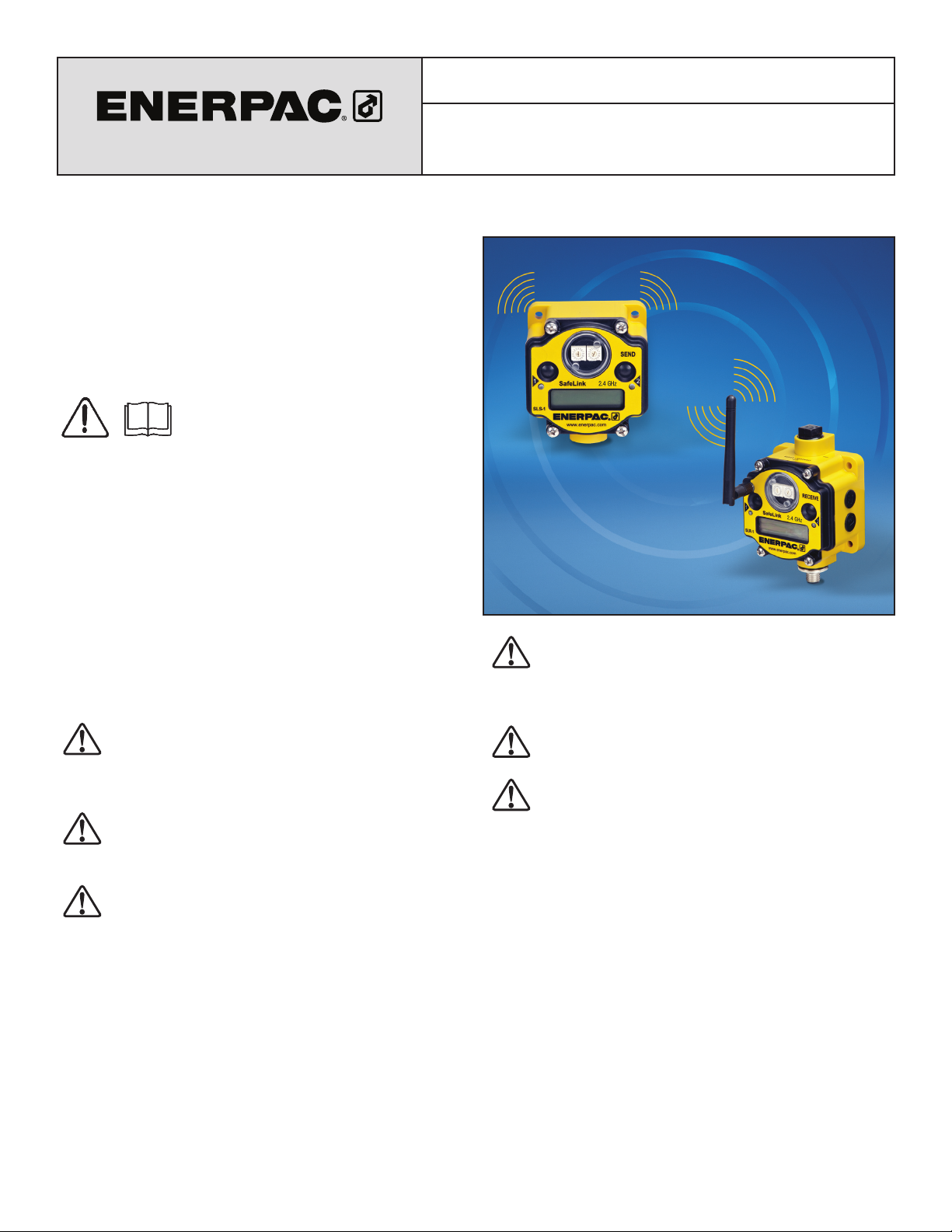
SafeLink Pallet Monitoring System
WARNING: Some SafeLink components are powered by
a 3.6 volt lithium battery. As with all batteries, there is a
fi re, explosion, and severe burn hazard risk. Do not burn
or expose the battery to high temperatures. Do not recharge,
crush, disassemble, or expose the contents to water.
WARNING: All live supply circuits must be disconnected
before wiring the machine control.
WARNING: To avoid personal injury, keep hands and feet
away from fi xture cylinder(s) and workpiece during
operation.
Note: All specifi cations published in this document are subject to
change. Enerpac reserves the right to modify the specifi cations of
products without notice. Enerpac reserves the right to update or
change documentation at any time.
1
Page 2
3.0 SPECIFICATIONS
Table 1 - General Specifi cations
IP Rating Meets IEC IP67 Standards. Dust tight, immersion up to one meter.
Radio Frequency 2.4 GHz, Global Standard
Transmit Power 21 dBm conducted
Input Power for Receive Unit (SLR-1, SLR-2) + 10 VDC to + 30 VDC Supplied by machine control.
Battery for Send Unit (SLS-1, SLS-2, SLS-3) 3.6 Volt Lithium Battery, Size D (Xeno XL-205F or equivalent).
Outputs + 24 VDC, NMOS Sinking
FCC Rating FCC part 15, Subpart C, 15.247
Receive Unit Communication Protocols
(SLR-1, SLR-2)
Receive Unit Outputs (SLR-1, SLR-2) 24 VDC, Maximum of 6 per unit, NPN Sinking
Modbus RTU RS485. Modbus TCP/IP or Ethernet IP when
system is equipped with SLEB-1 Ethernet Bridge.
4.0 MOUNTING DIMENSIONS
SEND UNIT
INPUT CAPABILITIES:
SLS-1 & SLS-2: Monitors
two inputs and contains
a communications check
channel (For use only
with receive unit Model
SLR-1).
SLS-3: Monitors three
inputs (For use only
with receive unit Model
SLR-2).
D1
D2
D1
D2
D3
(4X)
D5
D4
D6
SLR-1, SLR-2 Receive Unit
D3
(4X)
D4
D5
D8
D6
D7
D1
D2
D3
(4X)
D5
D4
D6
D8
Note: Antenna not shown.
D1
D2
SLEM-1 Expansion Module
D3
(4X)
D5
D4
D6
D7
SLS-1 Send Unit SLS-2, SLS-3 Send Unit
Note: Antenna not shown.
D1
D2
D4
SLEB-1 Ethernet Bridge
D3
(4X)
D5
D6
D7
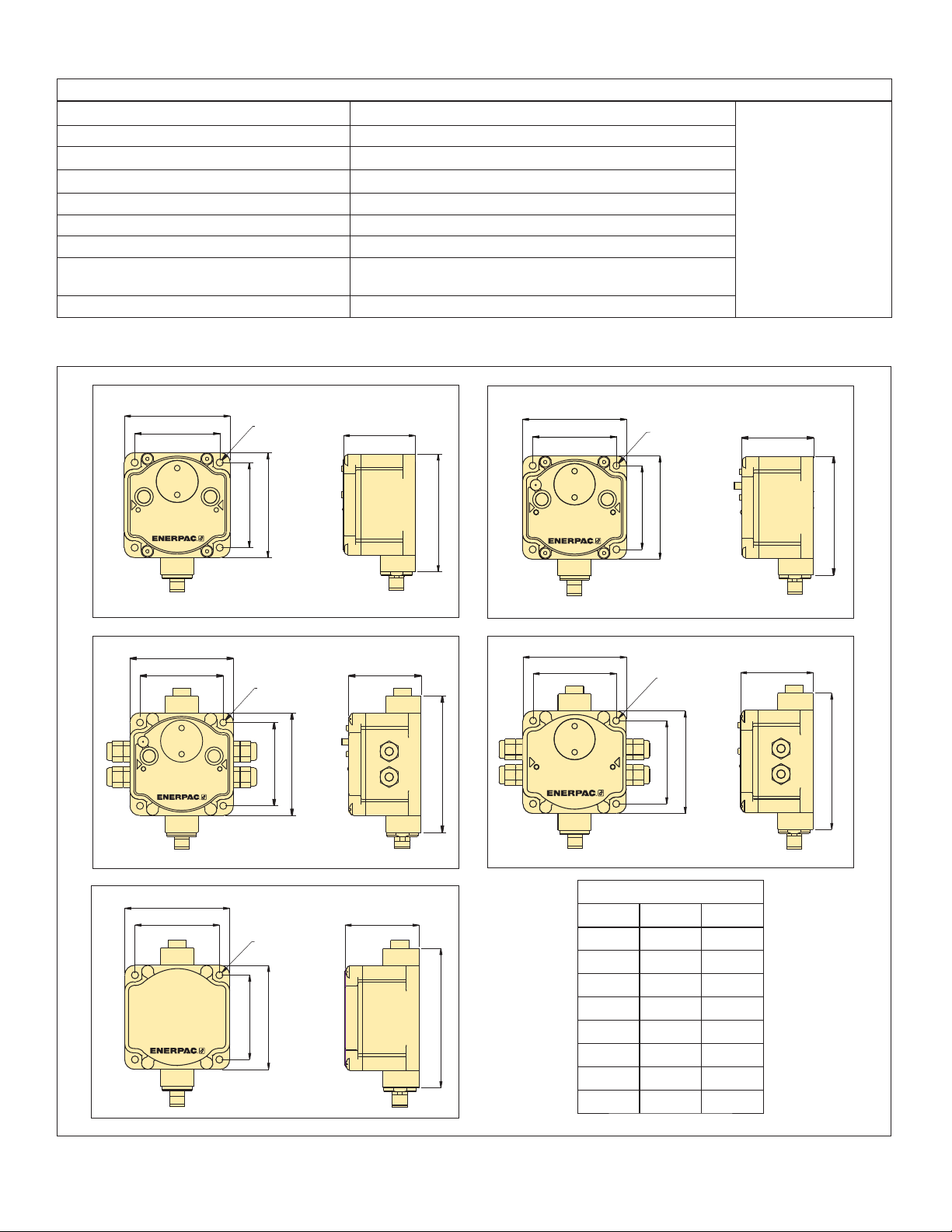
Dimensions
Item inch mm
D1
D2
D3
D4
D5
D6
D7
D8
3.18 80,8
2.56 65,0
Ø 0.22 Ø 5,5
2.56 65,0
3.16 80,1
2.23 56,6
4.20 106,7
3.67 93,2
Figure 1, Mounting Dimensions
2
Page 3

5.0 MAJOR FEATURES AND COMPONENTS
SLS-1, SLS-2 and SLS-3 Send Unit SLR-1 and SLR-2 Receive Unit
H
HHH
B C, D
E
A
F
G
I
Key:
A. LED indicator, #1
B. Push Button, #1
C. Rotary Switch, “Left”
D. Rotary Switch, “Right”
E. Push Button, #2
F. LED indicator, #2
G. LCD Display
H. Antenna (SLS-2, SLS-3,
SLR-1 and SLR-2 only)
I
B
C, D
A
G
K
I. 1/2" NPT Port (equipped with plug if not used)
J. Access Holes (equipped with caps if not used)
K. Quick Disconnect Serial Port, 5-Pin M12
E
J
F
SLEM-1 Expansion Module SLEB-1 Ethernet Bridge
I I
C, D
J
K K
Figure 2, Major Features and Components
Note: The Enerpac SLCS-1 Power and Communication Splitter
Cable (sold seperately - see Figure 17) is required for use with the
SLEM-1 Expansion model or the SLEB-1 Ethernet Bridge.
Note: Housing color on current production models is black. Yellow
housing shown in this manual is for illustrative purposes only, to
help ensure that product features and details are clearly visible.
3
Page 4

6.0 INSTALLATION
6.1 Overview
The SafeLink wireless pressure monitoring system continuously
monitors the clamping pressure in a fi xture during the machining
process. It is designed to be interfaced to the machine control so
the machine can be stopped immediately if clamping pressure is
lost. If desired, the SafeLink system can also be used to monitor
limit switch based position sensing on clamping cylinders.
The basic SafeLink system consists of a battery powered send
unit (SLS-1, SLS-2 or SLS-3) mounted in or on the fi xture, and
a matching receive unit (SLR-1 or SLR-2) that is connected and
interfaced to the machine control. Radio communication between
the two units is 2.4 GHz.
Pressure switches (sold separately) are installed in each fi xture
circuit to be monitored. Loss of pressure in one or more of the
switches is communicated from the send unit to the receive unit,
resulting in a fault condition being triggered. The machine control
will then initiate appropriate shut down of the machinery.
A special communication verifying feature in the receive unit
periodically queries the send unit every few seconds, to ensure
that it is responding. If there is no response, a fault condition
will be triggered, and the machine control will initiate appropriate
shut down of the machinery.
Up to 47 send units can be linked to one receive unit if
TCP/IP or Ethernet IP communication protocol is used. These
Modbus
protocols require the use of the SafeLink SLEB-1 Ethernet Bridge.
IMPORTANT: Installation and setup instructions are contained
in the following sections of this manual. These instructions are
intended only for use by experienced installation technicians with
appropriate skills and training. If custom installation services are
required, contact Enerpac for additional information.
6.2 Installing the SLR-1 or SLR-2 Receive Unit
The SLR-1 or SLR-2 receive unit should be mounted on an
external surface on the machine control enclosure, or inside of
the control enclosure on a DIN Rail using the Enerpac SLDB-1
DIN rail mounting bracket (optional accessory). See Figure 3.
6.3 Installing the SLS-1 Send Unit on a Fixture
The SLS-1 send unit must be mounted externally on the fi xture
in a location that does not expose the unit to excessive coolant
fl ow or fl ying chips.
It must be positioned so that the internal antenna can transmit
freely without interference. Use the four 5 mm mounting holes on
the base to securely mount the unit.
The SLS-1 is IEC rated at IP67, protected from dust and
immersion to 1 meter.
6.4 Installing the SLS-2 or SLS-3 Send Unit
on a Fixture
The SLS-2 and SLS-3 send units are intended to be mounted
inside of a fi xture (such as a four-sided tombstone) in a location
that does not expose the unit to excessive coolant fl ow or fl ying
chips. The SLS-2 and SLS-3 are IEC rated at IP67, protected
from dust and immersion to 1 meter. Use the four 5 mm mounting
holes on the base to securely mount the unit.
Both models contain an external antenna jack and separate
antenna. The antenna can be cabled if the fi xture has a cover.
Use the Enerpac SLS-2AC cable (optional accessory) to connect
either SLS send unit to an externally mounted antenna.
7.0 WIRING AND CONNECTIONS
7.1 Pressure Switch Installation and Wiring
All pressure switches should be located in a protected area,
where they are not exposed to excessive coolant fl ow or fl ying
chips. Wire each switch normally open, so that the circuit in the
pressure switch will close when the pressure setting is reached,
but will go open if the system pressure has decreased below
acceptable limits.
The use of an Enerpac PSCK-8 or PSCK-9 pressure switch
(optional accessory) is recommended. Connect wires to
terminals 1 and 3, so that the switch is wired normally open. See
Figure 4 for switch wiring details. Refer to Enerpac instruction
sheet L2391 for additional information regarding PSCK pressure
switch installation.
Figure 3, SLDB-1 DIN Rail Mounting Bracket (optional)
The SLR-1 and SLR-2 receive units require a connection to a 24
VDC power supply. A connection of the output from the SLR-1
or SLR-2 into the machine control is also required.
Note: The SLR receive units communicate to the machine
control via either a 24 VDC output or via Modbus RTU RS485
protocol. If Modbus TCP/IP or Ethernet IP protocols are used,
the optional SLEB-1 Ethernet Bridge is required. See sections 9
and 10 of this manual for additional information.
Both models contain an external antenna jack and separate
antenna. The antenna can be cabled if the control enclosure has
a cover. Use the Enerpac SLS-2AC cable (optional accessory)
to connect either SLR receive unit to an externally mounted
antenna.
1
3
2
PSCK-8, PSCK-9
Wiring Diagram
Function Terminal
Common 1
Normally Closed 2
Normally Open 3
Ground (not used) 4
1
3
DIN Style connector plug
(with protective cover removed)
1
3
2
2
4
Figure 4, Pressure Switch Connections (typical)
7.2 Wiring Pressure Switch to the Send Unit
(SLS-1, SLS-2 or SLS-3)
Connect the pressure switch to the SLS send unit as described
in the following procedure:
4
Page 5
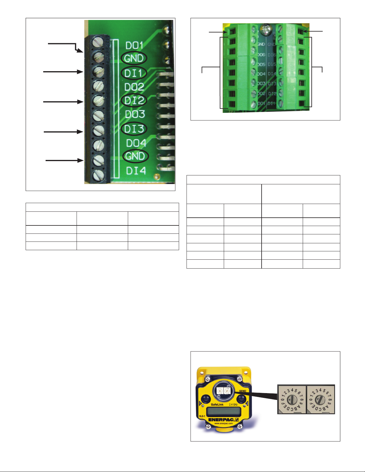
Ground Terminal
(GND)
Input 1 Terminal
(DI1)
Input 2 Terminal
DI2)
(
SLS-3 Only:
Input 3 Terminal
(
DI3)
Ground Terminal
(GND)
Figure 5, Send Unit Terminal Block (SLS-1, SLS-2, SLS-3)
Table 2 - SLS-1, SLS-2 and SLS-3 Wiring information
Input
Function
Input #1
Input #2
Input #3 (SLS-3 only)
SEND UNIT Input
Connection Terminal
DI1 GND
DI2 GND
DI3 GND
SEND UNIT Ground
Terminal
Remove the four screws that secure the face plate of the SLS
send unit. Locate the terminal strip inside the housing. See Figure
5.
Wire the leads from the pressure switch to the DI1 and ground
terminals per Table 2. Note that the strip contains two ground
(GND) connections. Use whichever one is most convenient. If
more than one pressure switch is used, be sure to connect them
in series.
A position sensing limit switch (if used) can be connected to
terminal DI2. Or, if desired, this terminal can instead be used to
connect one or more additional pressure switches.
IMPORTANT: Use only limit type position switches. Proximity
type switches are not compatible with the SafeLink system.
Note: For SLS-1 and SLS-2, communication input terminal
DI3 is assigned to a circuit that periodically checks for proper
operation of the sending unit during SafeLink operation. For SLS1 and SLS-2, DO NOT make any connections to terminal DI3.
Terminals DO1, DO2, DO3, DO4 and DI4 are NOT USED.
7.3 Connecting the 24 VDC Outputs of Receive Unit
SLR-1 or SLR-2 to the Machine Control
Note: This section covers typical connections using the standard
24 VDC I/O machine interface. If using Modbus RTU, Modbus
TCP/IP or Ethernet IP, please refer to sections 9 and 10 of this
manual.
Remove the four screws that secure the face plate of the SLR-1
or SLR-2 receive unit. Locate the receive unit terminal block. See
Figure 6.
PWR
Terminal
Output
Terminals
DO1 - DO6
PWR
Terminal
Input
Terminals
(not used)
Figure 6, Receive Unit Terminal Block (SLR-1, SLR-2)
Wire the output terminals of the SLR-1 or SLR-2 to the machine
control input terminals. Refer to Table 3 for SLR terminal block
connection information.
Note: Two + 24 VDC power terminals (PWR) are available at the
top of the terminal block. The DO-x outputs of the SLR receive
unit are pre-paired to the DI-x inputs of the SLS send unit.
Table 3 - SLR-1 and SLR-2 Wiring information
Send Unit ID and Input
(SLS-1, SLS-2, SLS-3)
ID # Input #
01
01
01 DI3* DO3* *
02
02
02
DI1 DO1 PWR
DI2 DO2 PWR
DI1 DO4 PWR
DI2 DO5 PWR
DI3
* DO6* *
8.0 SETUP
Receive Unit Terminals
(SLR-1, SLR-2)
See Figure 6
Output
(-24 VDC)
Power
(+24 VDC)
PWR
PWR
* SLS-3 only. * * SLR-2 only.
8.1 Selecting the Send Unit ID
Open clear round cover on SLS-1, SLS-2 or SLS-3.
Using the rotary switches, set the send unit ID. Start with “01” for
the fi rst send unit in your network. The second send unit would
be “02”. See Figure 7.
Note: The maximum number of send units that can be paired
with a receive unit will vary, depending on the communication
protocol being used. Refer to Section 9 of this manual for
additional information.
Set ID for each
SEND UNIT using
rotary switches.
5
Figure 7, Setting ID Number of SLS Send Unit
Page 6

Note: The rotary switches on the SLR receive unit are used only
to select the desired SLS send unit to be viewed on the receive
unit LCD display. They DO NOT determine the send unit ID.
Refer to Section 8.4 for additional information.
8.2 Turning Send Unit Power ON
Press and hold Button #1 on SLS send unit for 3-4 seconds
The display window will scroll though the status of each
possible I/O. LED #2 will fl ash red. See Figure 8.
Press and hold
Button #1 for
about 3 seconds
to turn ON.
LED #2 will
fl ash RED.
Figure 8, Turning Power ON - SLS Send Unit
8.3 Binding Send Unit to Receive Unit
Press Button #2 on the SLS send unit three times. The display
will show “NETWORK BINDING”. See Figure 9.
After binding occurs, the SLS send unit will fl ash BOUND
several times and will then begin scrolling. However, it will
remain in a standby mode until the SLR receive unit is returned
to the RUN mode.
Until the SLR receive unit is returned to the RUN mode, LED #2
on the SLS send unit will continue to fl ash red. Both LED #1 and
#2 on the receive unit will continue to fl ash alternately.
Note: At this time, repeat the binding procedure for any other
SLS send units in the network (if present).
After all SLS send units in the network have been bound,
press button #2 on the SLR receive unit once. The SLR
receive unit will exit BINDING mode and return to RUN mode.
Communication between the SLR receive unit and the SLS
send unit(s) is now enabled.
Note: After the SLR receive unit is placed in the RUN mode,
approximately 10-15 seconds will be required for the SLR
receive unit to begin communicating with the SLS send unit(s).
When the units begin communicating, LED #2 on the SLS send
unit will shut o and LED #1 will begin fl ashing green, indicating
that communication is in progress. See Figure 11.
On the SLR receive unit, LED #1 will change from fl ashing red to
a steady green. LED #2 will turn o . The display will then scroll
through an I/O status check. It will show “RUN”, the Network ID
(NID) of the system network and the status of each input (ON or
OFF). See Figure 13.
Note: Press Button #2 twice on either unit to stop the scrolling
display.
Press Button #2
on SEND UNIT three
times.
Display will show
“NETWORK BINDING”.
LED’s #1 and #2
will both fl ash RED.
Figure 9, Network Binding - SLS Send Unit
Press Button #2 on the SLR receive unit three times. Check that
display shows “BINDING”. This indicates that the radios in the
SLS and the SLR units are seeking each other. See Figure 10.
Press Button #2
on RECEIVE UNIT
three times.
Display will show
“BINDING”.
LED’s #1 and #2
will both fl ash RED.
Figure 10, Network Binding - SLR Receive Unit
Press button #2 once
on SLR RECEIVE
UNIT to return to
RUN mode and start
communication.
Figure 11, Starting Communication - SLR Receive Unit
LED #2 will be OFF.
LED #1 will fl ash GREEN
when SEND UNIT begins
communicating with
RECEIVE UNIT.
Figure 12, Communication In Progress - SLS Send Unit
6
Page 7

Display will begin scrolling
when RECEIVE UNIT is
placed in RUN mode.
LED #1 will turn GREEN
when SEND UNIT begins
communicating with
RECEIVE UNIT.
Figure 13, RUN Mode - SLR Receive Unit
7. Press button #1 to scroll to “RUN”.
8. The display will scroll through the status of the SLS send
unit selected by the rotary switches on the SLR receive
unit.
Press Button #1 on RECEIVE
UNIT to scroll to site.
Press button #2 to
begin viewing the
selected SEND UNIT.
Press button #2 again
to start the survey of
the signal strength.
8.4 Checking Signal Strength
The SLR-1 or SLR-2 can be used to measure the strength
of the wireless signal between each SLS send unit and the
SLR receive unit. Measure signal strength as described in the
following steps:
1. On the SLR receive unit, Set the rotary switches to the ID
number of the desired send unit to be viewed. See Figure
14.
Set RECEIVE UNIT rotary
switches to desired SEND
UNIT ID to be viewed.
Figure 14, Selecting Send Unit to be Viewed
by SLR Receive Unit
2. Press button #1 to scroll to “#SITE”.
3. Press button #2 to start SLR viewing mode. “NOD x” will
appear on the display (x = ID number of the SLS send unit
to be viewed by the SLR-1 receive unit). See Figure 15.
Press button #2 again to start the survey of the signal
4.
strength between the SLS send unit and the SLR receive
unit.
G = Good Signal Strength
Y = Medium Signal Strength
R = Low Signal Strength
M = Missed Signals
Note: The number (1-100) following the G, Y, R or M
indicates how many signal checks out of 100 are G, Y, R or
M.
5. Press button #2 twice to return to “NOD x”.
6. Press button #2 twice to set to “#SITE”.
Figure 15, Checking Signal Strength - SLR Receive Unit
8.5 LED Status Indicator Lights
During operation of the system, the LED lights provide a quick
visual indication of the status of the send units and the receive
unit.
See Tables 4 and 5.
Table 4 - SLR-1 and SLR-2 Receive Unit Status Indicators
STATUS LED 1 LED 2
Power ON
Modbus
Communication
Active
Modbus
Communication
Error
System Error
Green
OFF
OFF
Red Flash
Table 5 - SLS-1, SLS-2 & SLS-3 Send Unit Status Indicators
STATUS LED 1 LED 2
Green Flash
RF Link OK
(1 per second)
RF Link Error
System Error
OFF
Red Flash
OFF
Yellow Flash
Red Flash
(1 every 3 seconds)
Red Flash
OFF
Red Flash
(1 per second)
Red Flash
(1 per second)
7
Page 8

8.6 Removing an SLS Send Unit from the Network
Before taking a fixture out of service or moving it to another
system, the fixture’s SLS send unit must be removed from the
network.
Use the following procedure to unbind an SLS-1, SLS-2 or
SLS-3 send unit from an SLR-1 or SLR-2 receive unit:
Note: Refer to Section 5.0 for button locations.
1. On the SLS send unit, press and hold button #1 for 3 to 4
seconds. This will turn-off the send unit.
2. On the SLR receive unit:
• Check that the display shows “ERROR”.
• Press button #2 once.
Check that the display shows “NOD x”
Note: “x” is the ID number (node) of the SLS send unit that
was turned-o in step 1.
• Press button #2 again.
Check that the display shows “EC 53”.
• Press button #1.
Check that the display shows “CLEAR”.
• Press button #2 to accept the changes.
Check that the display shows “ERASED”.
The SLS send unit should now be unbound from the SLR
receive unit. It will no longer be included in the network.
9.0 SETTING UP EXPANDED SYSTEMS
Refer to Table 6 for an overview of SafeLink expansion
possibilities.
If only one or two additional SLS send units are required, the
SLEM-1 Expansion Unit can be used. For systems requiring
greater numbers of additional SLS send units (such as a pallet
pool system) the interface to the machine control can be
achieved using either the standard 5-Pin serial port connection
located on the SLR receive unit or by using the SLEB-1
Ethernet Bridge. The SLEB-1 allows the SafeLink system to be
connected to an Ethernet network.
9.1 Using the SLEM-1 Expansion Module
For systems with up to 4 fi xtures, where 24 VDC output is the
desired interface to the machine control, the SLEM-1 Expansion
Module (optional accessory) provides additional expansion
capabilities. The SLEM-1 allows up to two additional SLS send
units to be added to the SafeLink system.
The output terminal block of the SLEM-1 is the same as
that used on the SLR receive unit. See Figure 6 for wiring
instructions.
9.2 Setting up a Modbus Based System
For machine controls that use Modbus RTU or TCP protocols,
the SLR-1 and SLR-2 receive units provide a built in Modbus
system.
The Modbus Serial Line RTU protocol is a master-slave protocol
typically used for industrial applications. It is an open standard
implementation of Modbus based on Internet protocols.
Modbus TCP/IP is similar to Modbus RTU but transmits
information within TCP/IP data packets.
Table 6 - Expanded System Data and Recommendations
Number of
fi xtures:
1 SLS-1, SLS-2 or SLS-3 3 SLR-1 or SLR-2 24 VDC 6
2 SLS-1, SLS-2 or SLS-3 3 SLR-1 or SLR-2 24 VDC 6
3 to 4 SLS-1, SLS-2 or SLS-3 3 SLR-1 or SLR-2 with SLEM-1 24 VDC 12
5 or more
SafeLink send unit
model number:
SLS-1, SLS-2 or SLS-3 3 Modbus from SLR-1 or SLR-2 Modbus 47
SLS-1, SLS-2 or SLS-3 3 SLR-1 or SLR-2 with SLEB-1 Ethernet 47
Number of outputs
available from each
send unit:
Recommended connection to
machine control:
Output protocol:
Number of
outputs to
machine control:
Table 7 - Modbus Holding Registers
I/O Port Receive #1 Send #1 Send #2 Send #3 Send #4 Send #5 Send #6 Send #7 Send #8
1 173349658197113129
2 183450668298114130
3 193551678399115131
8 24 40 56 72 88 104 120 136
99
10 10
11 11
12 12
13 13
14 14
8
Page 9

Modbus RTU is the native protocol for the SafeLink system.
All wireless devices are organized with a two-byte register
for each I/O point. Sixteen registers are allocated for each
device, typically eight registers for inputs and eight registers
for outputs. For Modbus, these registers are addressed
consecutively beginning with the Receive (SLR-1 or SLR-2)
then Send 1 (SLS-1, SLS-2 or SLS-3) through Send (N) (SLS-1,
SLS-2 or SLS-3).
Go to www.modbus.org for additional information regarding
Modbus.
9.3 Holding Registers
Refer to Table 7 for additional information.
There are 16 Modbus holding registers for each SafeLink
device. A holding register is the location in the internal memory
of a PLC for a particular input. For example, in Table 7, I/O port
1 for Send#1 is register 17. This may correspond to a pressure
switch used on I/O port 1 in Send #1. Calculate the holding
register number for each device using the following equation:
Register number = 40,000 + (I/O # + (Send # x 16))
9.4 Modbus Connection to Controller
The Modbus output from the SLR-1 or SLR-2 receive unit is
through the 5pin European style serial connector located at the
bottom of the housing. See Figure 16 for wiring information.
A power and communication cable is supplied with the SLR-1
or SLR-2 receive unit. Additional components not included with
the SafeLink system may be required to interface with various
controllers. See your machine supplier for information on
required adaptors and other items that may be needed for your
installation.
9.5 Setting up Ethernet IP Communication
Ethernet setup is the same as for a Modbus based system.
Refer to Table 7 to determine the register assignments.
The default IP address for the SLEB-1 Ethernet Bridge is
IP 192.168.0.1.
Contact Enerpac for additional information if you wish to
reassign the SLEB-1 to a di erent IP address.
9.6 SLCS-1 Power and Communication Splitter Cable
The Enerpac SLCS-1 (optional
accessory) is used to connect the
SLEB-1 Ethernet Bridge and the SLR-1
or SLR-2 receive unit to the machine
controller and Ethernet network. See
Figure 17.
The SLCS-1 is also required when
using an SLEM-1 Expansion Module
with a standard 24 VDC I/O machine
interface.
Refer to Figures 19 through 25 in
Section 10.0 for typical hookups using
the SLCS-1.
Figure 17, SLCS-1
Wire No Wire Color Description
1 Brown 10 to 30 VDC
2 White RS485 / D1 / B / +
3 Blue DC Common (Ground)
4 Black RS485 / D0 / A /-
5 Gray Communications Ground
CAUTION: DO NOT connect DC Power to pins #2
(white wire) #4 (black wire) or #5 (gray wire). Doing
so will cause permanent damage to the SLR receive
unit. Such damage is not covered under warranty.
Figure 16, 5-Pin Serial Port Connector (SLR-1 or SLR-2)
9
Page 10

10.0 TYPICAL SYSTEM LAYOUTS
PALLET #1
Input #1
Input #2
SLS-1 or SLS-2
PALLET #1
Input #1
Input #2
SEND/RECEIVE connected
“SEND” unit
SLR-1
“RECEIVE”
unit
PALLET #2
Input #1
Input #2
SLS-1 or SLS-2
PALLET #2
Input #1
Input #2
SEND/RECEIVE connected
“SEND” unit
Figure 18, Basic System with I/O Machine Interface
(SLS-1 or SLS-2 with SLR-1)
machine controller
Output to machine controller: 24 VDC from RECEIVE unit.
PALLET #1
Input #1
Input #2
SLS-1 or SLS-2
PALLET #1
Input #1
Input #2
SEND/RECEIVE connected
“SEND” unit
PALLET #2
Input #1
Input #2
SLS-1 or SLS-2
SLCS-1
“SPLITTER
CABLE”
PALLET #2
Input #1
Input #2
SEND/RECEIVE connected
“SEND” unit
PALLET #3
Input #1
Input #2
SLS-1 or SLS-2
“SEND” unit
PALLET #4
Input #1
Input #2
SLR-1
“RECEIVE”
unit
SLEM-1
“EXPANSION
MODULE”
PALLET #3
Input #1
Input #2
SEND/RECEIVE connected
PALLET #4
Input #1
Input #2
SEND/RECEIVE connected
machine controller
SLS-1 or SLS-2
“SEND” unit
Figure 19, Larger System with I/O Machine Interface (SLS-1 or SLS-2 with SLR-1)
Output to machine controller: 24 VDC from RECEIVE unit and EXPANSION
MODULE.
10
Page 11

PALLET #1
Input #1
Input #2
SLS-1 or SLS-2 “SEND” unit
PALLET #2
Input #1
Input #2
SLS-1 or SLS-2 “SEND” unit
SLR-1
PALLET #3
Input #1
Input #2
“RECEIVE”
unit
SLS-1 or SLS-2 “SEND” unit
PALLET #4
Input #1
Input #2
SLS-1 or SLS-2 “SEND” unit
Figure 20, Larger System with Modbus RTU Machine Interface
(SLS-1 or SLS-2 with SLR-1)
PALLET #1
Input #1
Input #2
SLS-1 or SLS-2 “SEND” unit
machine controller
Output to machine controller: Modbus RTU RS-485.
PALLET #2
Input #1
Input #2
SLCS-1
“SPLITTER
CABLE”
SLS-1 or SLS-2 “SEND” unit
PALLET #3
Input #1
Input #2
SLS-1 or SLS-2 “SEND” unit
SLR-1
“RECEIVE”
unit
SLEB-1
“ETHERNET
BRIDGE”
PALLET #4
Input #1
Input #2
SLS-1 or SLS-2 “SEND” unit
machine controller
Output to machine controller: Ehternet IP or Modbus TCP/IP.
Figure 21, Larger System with Ethernet IP Machine Interface (SLS-1 or SLS-2 with SLR-1)
11
Page 12

PALLET #1
Input #1
Input #2
Input #3
SLS-3 “SEND” unit
PALLET #1
Input #1
Input #2
Input #3
PALLET #2
Input #1
Input #2
Input #3
SLS-3 “SEND” unit
Figure 22, Basic System with I/O Machine Interface
PALLET #1
Input #1
Input #2
Input #3
SLS-3 “SEND” unit
SLR-2
“RECEIVE”
unit
PALLET #2
Input #1
Input #2
Input #3
(SLS-3 with SLR-2)
PALLET #1
Input #1
Input #2
Input #3
machine controller
Output to machine controller: 24 VDC from RECEIVE unit.
PALLET #2
Input #1
Input #2
Input #3
SLCS-1
“SPLITTER
CABLE”
PALLET #2
Input #1
Input #2
Input #3
SLS-3 “SEND” unit
PALLET #3
Input #1
Input #2
Input #3
SLS-3 “SEND” unit
PALLET #4
Input #1
Input #2
Input #3
SLR-2
“RECEIVE”
unit
SLEM-1
“EXPANSION
MODULE”
PALLET #3
Input #1
Input #2
Input #3
PALLET #4
Input #1
Input #2
Input #3
SLS-3 “SEND” unit
Figure 23, Larger System with I/O Machine Interface (SLS-3 with SLR-2)
12
machine controller
Output to machine controller: 24 VDC from RECEIVE unit and EXPANSION
MODULE.
Page 13

PALLET #3
Input #1
Input #2
Input #3
SLS-3 “SEND” unit
PALLET #3
Input #1
Input #2
Input #3
SLS-3 “SEND” unit
SLR-2
“RECEIVE”
unit
PALLET #3
Input #1
Input #2
Input #3
SLS-3 “SEND” unit
PALLET #3
Input #1
Input #2
Input #3
SLS-3 “SEND” unit
Figure 24, Larger System with Modbus RTU Machine Interface
(SLS-3 with SLR-2)
machine controller
Output to machine controller: Modbus RTU RS-485.
13
Page 14

PALLET #1
Input #1
Input #2
Input #3
SLS-3 “SEND” unit
PALLET #1
Input #1
Input #2
Input #3
SLS-3 “SEND” unit
PALLET #1
Input #1
Input #2
Input #3
SLS-3 “SEND” unit
SLCS-1
“SPLITTER
CABLE”
SLR-2
“RECEIVE”
unit
SLEB-1
“ETHERNET
BRIDGE”
machine controller
PALLET #1
Input #1
Input #2
Input #3
SLS-3 “SEND” unit
Figure 25, Larger System with Ethernet IP Machine Interface
Output to machine controller: Ehternet IP or Modbus TCP/IP.
(SLS-3 with SLR-2)
14
Page 15

11.0 MAINTENANCE
Follow these instructions to perform basic maintenance tasks.
11.1 Replacing The Main Body Gasket
Check the main body
gasket every time the
device is opened.
Replace the gasket
when it is damaged,
discolored, or showing
signs of wear.
The gasket must be:
• Fully seated within its
channel along the full
length of the perimeter,
and. . .
• Positioned straight
within the channel with
no twisting, stress, or
stretching.
Figure 26, Main Body Gasket
11.2 Replacing The Rotary Dial Cover
Check the o-ring on the rotary switch access cover whenever the
access cover is removed. Replace the o-ring when it is damaged,
discolored, or showing signs of wear.
The o-ring should be:
• Seated fi rmly against the
threads without stretching
to fi t or without bulging
loosely, and. . .
• Pushed against the
fl anged cover.
When removing or closing
the rotary switch access
cover, manually twist the
cover into position.
Do not allow crossthreading between the
cover and the device’s
face.
Once the cover is in place and manually tightened, use a small
screwdriver (no longer than 5 inches [127 mm] total length) as a
lever to apply enough torque to bring the rotary switch access
cover even with the cover surface.
Figure 27, Rotary Switch Cover
11.3 Battery Replacement
To replace the lithium “D” cell battery in the SLS-1, SLS-2 or
SLS-3 send unit, follow these steps:
1. Remove the four screws mounting the device face plate to
the housing and remove the face plate.
2. Remove the discharged battery and replace with a new
battery. Use only a 3.6V lithium battery from Xeno, model
number XL-205F.
3. Verify the battery’s positive and negative terminals align to
the positive and negative terminals of the battery holder
mounted within the case. The negative end is toward the
spring. Caution: There is a risk of explosion if the battery is
replaced incorrectly.
4. After replacing the battery, allow up to 60 seconds for the
device to power up.
Figure 28, Battery
(SLS-1, SLS-2 and SLS-3 Only)
When removing the battery, press the battery towards the
negative terminal to compress the spring. Pry up on the battery’s
positive end to remove from the battery holder. Properly dispose
of your used battery according to local regulations by taking it to
a hazardous waste collection site, an e-waste disposal center, or
other facility qualifi ed to accept lithium batteries.
WARNING: As with all batteries, these is a fi re,
explosion, and severe burn hazard risk. Do not burn or
expose the battery to high temperatures. Do not
recharge, crush, disassemble, or expose the contents to water.
12.0 PRODUCT WARRANTY
SafeLink products are warranted by Enerpac to be free from
defects in material and workmanship for 2 years following the
date of shipment. Enerpac will repair or replace, free of charge,
any SafeLink product which, at the time it is returned to the
factory, is found to have been defective during the warranty
period. This warranty does not cover damage or liability for
misuse, abuse, or the improper application or installation of the
SafeLink product.
THIS LIMITED WARRANTY IS EXCLUSIVE AND IN LIEU OF
ALL OTHER WARRANTIES WHETHER EXPRESS OR IMPLIED
(INCLUDING, WITHOUT LIMITATION, ANY WARRANTY
OF MERCHANTABILITY OR FITNESS FOR A PARTICULAR
PURPOSE), AND WHETHER ARISING UNDER COURSE OF
PERFORMANCE, COURSE OF DEALING OR TRADE USAGE.
This Warranty is exclusive and limited to repair or, at the
discretion of Enerpac, replacement. IN NO EVENT SHALL
ENERPAC BE LIABLE TO BUYER OR ANY OTHER PERSON
OR ENTITY FOR ANY EXTRA COSTS, EXPENSES, LOSSES,
LOSS OF PROFITS, OR ANY INCIDENTAL, CONSEQUENTIAL
OR SPECIAL DAMAGES RESULTING FROM ANY PRODUCT
DEFECT OR FROM THE USE OR INABILITY TO USE THE
PRODUCT, WHETHER ARISING IN CONTRACT OR WARRANTY,
STATUTE, TORT, STRICT LIABILITY, NEGLIGENCE, OR
OTHERWISE.
Enerpac reserves the right to change, modify or improve the
design of the product without assuming any obligations or
liabilities relating to any product previously manufactured by
Enerpac.
15
Page 16

Enerpac Worldwide Locations e-mail: info@enerpac.com internet: www.enerpac.com
Australia and New Zealand
Actuant Australia Ltd.
Block V Unit 3
Regents Park Estate
391 Park Road
Regents Park NSW 2143
(P.O. Box 261) Australia
T +61 (0)2 9743 8988
F +61 (0)2 9743 8648
sales-au@enerpac.com
Brazil
Power Packer do Brasil Ltda.
Rua
Luiz Lawrie Reid, 548
09930-760
T +55 11 5525 2311
Toll Free: 0800 891 5770
vendasbrasil@enerpac.com
Canada
Actuant Canada Corporation
6615 Ordan Drive, Unit 14-15
Mississauga, Ontario L5T 1X2
T +1 905 564 5749
F +1 905 564 0305
Toll Free:
T +1 800 268 4987
F +1 800 461 2456
customer.service@actuant.com
China
Actuant (China) Industries Co. Ltd.
No. 6 Nanjing East Road,
Taicang Economic Dep Zone
Jiangsu, China
T +86 0512 5328 7500
F +86 0512 5335 9690
Toll Free: +86 400 885 0369
sales-cn@enerpac.com
France, Switzerland, North Africa
and French speaking African
countries
ENERPAC
Une division d’ACTUANT France S.A.
ZA de Courtaboeuf
32, avenue de la Baltique
91140 VILLEBON /YVETTE
France
T +33 1 60 13 68 68
F +33 1 69 20 37 50
sales-fr@enerpac.com
-
Diadema (SP) - Brazil
Germany and Austria
ENERPAC GmbH
P.O. Box 300113
D-40401 Düsseldorf
Willstätterstrasse 13
D-40549 Düsseldorf, Germany
T +49 211 471 490
F +49 211 471 49 28
sales-de@enerpac.com
India
ENERPAC Hydraulics Pvt. Ltd.
No. 1A, Peenya Industrial Area
IInd Phase, Bangalore, 560 058, India
T +91 80 40 792 777
F +91 80 40 792 792
sales-in@enerpac.com
Italy
ENERPAC S.p.A.
Via Canova 4
20094 Corsico (Milano)
T +39 02 4861 111
F +39 02 4860 1288
sales-it@enerpac.com
Japan
Applied Power Japan LTD KK
Besshocho 85-7
Kita-ku, Saitama-shi 331-0821, Japan
T +81 48 662 4911
F +81 48 662 4955
sales-jp@enerpac.com
Middle East, Egypt and Libya
ENERPAC Middle East FZE
Oce 423, LOB 15
P.O. Box 18004, Jebel Ali, Dubai
United Arab Emirates
T +971 (0)4 8872686
F +971 (0)4 8872687
sales-ua@enerpac.com
Russia
Rep. oce Enerpac
Russian Federation
Admirala Makarova Street 8
125212 Moscow, Russia
T +7 495 98090
F +7 495 98090 92
sales-ru@enerpac.com
Southeast Asia, Hong Kong
and Taiwan
Actuant Asia Pte Ltd.
83 Joo Koon Circle
Singapore 629109
T +65 68 63 0611
F +65 64 84 5669
Toll Free: +1800 363
sales-sg@enerpac.com
91
7722
South Korea
Actuant Korea Ltd.
3Ba 717, Shihwa Industrial Complex
Jungwang-Dong, Shihung-Shi,
Kyunggi-Do
Republic of Korea 429-450
T +82 31 434 4506
F +82 31 434 4507
sales-kr@enerpac.com
Spain and Portugal
ENERPAC SPAIN, S.L.
Avda. Los Frailes, 40 – Nave C & D
Pol. Ind. Los Frailes
28814 Daganzo de Arriba
(Madrid) Spain
T +34 91 884 86 06
F +34 91 884 86 11
sales-es@enerpac.com
Sweden, Denmark, Norway, Finland
and Iceland
Enerpac Scandinavia AB
Fabriksgatan 7
412 50 Gothenburg
Sweden
T +46 (0) 31 799 0281
F +46 (0) 31 799 0010
scandinavianinquiries@enerpac.com
The Netherlands, Belgium,
Luxembourg,
Central and Eastern Europe,
Baltic States, Greece, Turkey
and CIS countries
ENERPAC B.V.
Galvanistraat 115
6716 AE Ede
P.O. Box 8097
6710 AB Ede
The Netherlands
T +31 318 535 911
F +31 318 535 848
sales-nl@enerpac.com
Enerpac Integrated Solutions B.V.
Opaalstraat 44
7554 TS Hengelo
P.O. Box 421
7550 AK Hengelo
The Netherlands
T +31 74 242 20 45
F +31 74 243 03 38
integratedsolutions@enerpac.com
South Africa and other English
speaking African countries
Enerpac Africa Pty Ltd.
No. 5 Bauhinia Avenue
Cambridge Oce Park
Block E
Highveld Techno Park
Centurion 0157
South Africa
T: +27 12 940 0656
United Kingdom and Ireland
ENERPAC UK Ltd.
5 Coopies Field
Morpeth, Northumberland
NE61 6JR, England
T +44 (0)121 50 50 787
F +44 (0)121 50 50 799
sales-uk@enerpac.com
USA, Latin America and Caribbean
ENERPAC
P.O. Box 3241
Milwaukee WI 53201 USA
T +1 262 293 1600
F +1 262 293 7036
User inquiries:
T +1 800 433 2766
Distributor inquiries/orders:
T +1 800 558 0530
F +1 800 628 0490
Technical inquiries:
techservices@enerpac.com
sales-us@enerpac.com
All Enerpac products are guaranteed
against defects in workmanship and
materials for as long as you own them.
For the location of your nearest authorized
Enerpac Service Center, visit us at
www.enerpac.com
121313
 Loading...