

Page 1
Instruction Sheet
S-Series
Hydraulic Torque Wrenches
EIS 59.113-1
08/2005
Page 2

Choose the required product series
from the left side of the screen, then
click on the required language.
The following languages are listed:
CD with Instruction Manuals in PDF-format
Please find the CD enclosed in the back of this manual
English
Français
Deutsch
Italiano
Español
Nederlands
Portuguese
Svenska
Norsk
Suomi
Pycc
КИЙ
The install program of the Acrobat
Reader 6.0 is included on the CD.
Page 3
ENGLISH
3
Index
1 Introduction . . . . . . . . . . . . . . . . . . . . . . . . . . . . . . . . . . . . . . . . . . . . . . . 4
2 Safety . . . . . . . . . . . . . . . . . . . . . . . . . . . . . . . . . . . . . . . . . . . . . . . . . . . . 4
3 Assembly and adjustments . . . . . . . . . . . . . . . . . . . . . . . . . . . . . . . . . . 6
4 Operation . . . . . . . . . . . . . . . . . . . . . . . . . . . . . . . . . . . . . . . . . . . . . . . . . 9
5 Maintenance and troubleshooting . . . . . . . . . . . . . . . . . . . . . . . . . . . . . 11
6 Technical specifications . . . . . . . . . . . . . . . . . . . . . . . . . . . . . . . . . . . . . 15
7 Recommended spare parts . . . . . . . . . . . . . . . . . . . . . . . . . . . . . . . . . . .19
Instruction manual Torque wrench
S-series
Page 4

4
ENGLISH
Enerpac declares that these models meet
the applicable standards and directives
issued by the European Community.
For a detailed list refer to the separate
certification sheet.
2 Safety
Be aware that the operator is fully
responsible during the operation of this
tool. Enerpac is not responsible for
damage or injury caused by misuse of this
tool. Under some circumstances additional
safety requirements may be required.
Contact Enerpac immediately if a
potentially hazardous situation arises.
Read this manual carefully and observe all
safety precautions.
- Make sure you have completed a
safety induction training, specific to
the work surroundings. The operator
should be thoroughly familiar with the
controls and the proper use of the
tool.
- The operator must be at least 18
years of age.
- Always wear protective headwear, ear
protectors, footwear and gloves (at a
minimum rigger type gloves) suitable
for safe operation of the tool. The
protective clothing must not interfere
with safe operation of the tool or
restrict the ability to communicate
with co-workers.
- Make sure your workplace is safe.
- Do not place any part of the body
between the reaction arm and the
reaction point.
- Do not place any objects between the
reaction arm and the reaction point.
Keep the hoses away from the
reaction points.
1 Introduction
Enerpac S-Series
The Enerpac S-series of lightweight
hydraulic wrenches have been designed to
tighten and loosen nuts and bolts for
professional applications. The tool has an
interchangeable drive shaft for which a
wide range of socket sizes are available.
The adjustable reaction arm further
enhances the flexibility of the tool.
The tool easily connects to the range of
available Enerpac pumps. Enerpac can
supply air, electric or hand operated
pumps.
Delivery instructions
Upon delivery all components must be
inspected for damage incurred during
shipping. If damage is found the carrier
should be notified at once. Shipping
damage is not covered by the Enerpac
warranty.
Warranty
• Enerpac guarantees the product only
for the purpose for which is intended.
• All Enerpac products are guaranteed
against defects in workmanship and
materials for as long as you own
them.
Any misuse or alteration invalidates the
warranty.
• Observe all instructions as laid down
in this manual.
• Replace any parts with Enerpac spare
parts only.
CE Declaration of conformity
S1500/S3000/S6000/S11000/S25000
Page 5

ENGLISH
5
- Do not stand in the line of movement
of the tool when it is in operation. If
the tool separates from the nut or bolt
during operation it will detach in that
direction.
- Tightening and loosening nuts and
bolts involves little visible movement.
The pressure and loads, however are
extreme. Keep your hands away from
the fastener being loosened or
tightened.
- Make sure that the spanner used to
keep the nut or bolt on the opposite
end is secured.
- Always use Enerpac pumps and
hoses.
- Make sure appropriate guards are
always securely in position and free
from damage.
- Maximum pressure is 690 bar (10,000
psi). Never apply more pressure to
any tool or accessory than the
maximum allowable pressure. Refer to
the technical data tables for maximum
pressure setting.
- Make sure that the socket size
corresponds to the size of the
fastener being loosened or tightened.
Always make sure that the socket
receptacle corresponds to the drive
shaft. Failure to do so can result in the
tool becoming unstable and can lead
to catastrophic failure.
- Do not abuse or overstress the hoses
in any way. Do not bend the hoses
excessively.
- Never carry the tool by its hoses.
- Always use Enerpac spare parts.
- Always position the tool for maximum
stability.
- Make sure reaction points are
adequate for the forces at work
during operation of the tool.
- Be aware that a nut or bolt that
breaks off during operation of the tool
will become a high velocity projectile.
- Make sure the reaction point is of a
suitable shape. For example use an
adjacent nut or bolt as a reaction
point.
- When the hex socket is placed on the
nut or bolt a gap may exist between
the reaction arm and the reaction
plate. When the tool is operated the
reaction arm and point will make
forceful contact. Always make sure
the tool is stable.
- Provide adequate support in vertical
and inverted applications.
- The maximum torque output of the
tool must always exceed the torque
required to loosen or tighten the nut
or bolt.
- The torque required to loosen a nut is
variable and may exceed the torque
capacity of the tool. Therefore never
operate the tool at maximum or close
to maximum capacity when loosening
a nut or bolt.
- Never operate the tool with a
hydraulic supply connection to the
advance side only as this may
damage the internal parts.
- If the wrench is dropped from a
height, have the tool inspected before
you operate it again.
- In severe conditions the tool must be
cleaned and lubricated more frequently.
- Make sure to minimize torsional and
bending stresses in the tool, the
ratchet and any accessories.
- Do not strike the tool with a hammer
while under a full load. This will
invalidate the guarantee.
- Use of extension pieces or long-reach
sockets is not recommended. They
increase torsional and bending stresses,
and reduce stability of the tool.
- Always observe the maintenance
instructions.
Page 6
6
ENGLISH
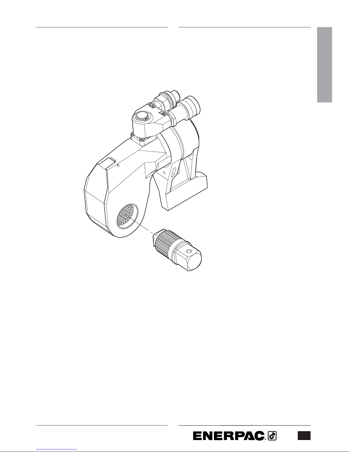
Fig. A
3 Assembly and adjustments
3.1 Overview and features (fig. A)
1 Drive shaft
2 Drive shaft release button
3 Swivel coupling
4 Advance hose connection
5 Return hose connection
6 Reaction arm
7 Reaction arm latch
3.2 To attach and remove the drive
shaft (fig. B)
Make sure to depressurize and
disconnect the tool from the hydraulic
supply first.
3.2.1 To attach the drive shaft
• Insert the drive shaft (1) into the
ratchet (8).
• Press the release button (2) and keep
it depressed.
• Push and turn the drive shaft until it
locks into place.
Make sure the drive shaft fits tightly
into the ratchet.
3.2.2 To remove the drive shaft
• Press the release button (2) and keep
it depressed.
• Pull the drive shaft (1) until it is
released.
• Remove the drive shaft from the
ratchet (8).
3.3 To select the drive direction (fig. B)
• For tightening operations, fit the drive
shaft (1) to the tool as shown.
• For loosening operations, fit the drive
shaft to the opposite side of the tool.
8
1
2
4
3
5
6
1
7
2
Fig. B
Page 7
ENGLISH
7
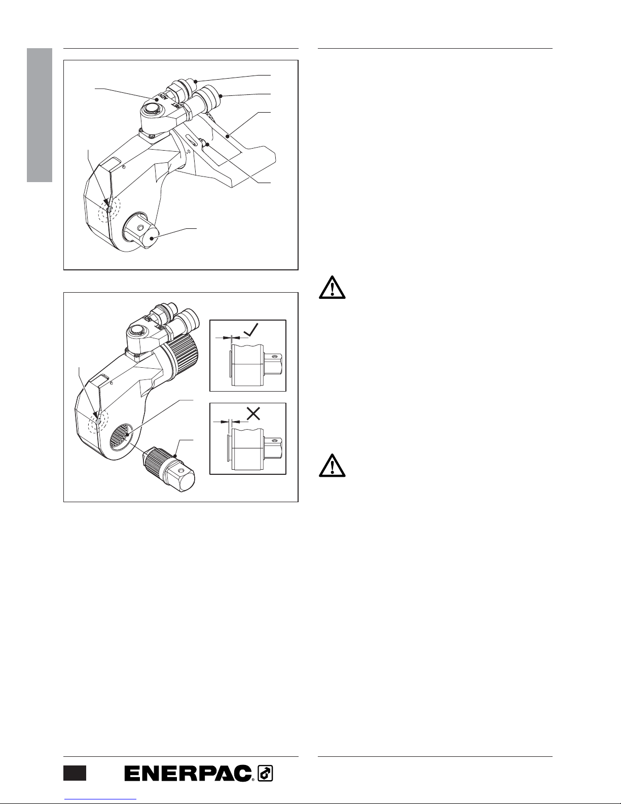
Fig. C
3.4 To fit and remove a hex socket
(fig. C)
3.4.1 To fit a hex socket
• Position the socket (9) onto the drive
shaft (1).
• Fit the retaining pin (10).
3.4.2 To remove a hex socket
• Remove the retaining pin (10).
• Take the socket (9) off the drive shaft
(1).
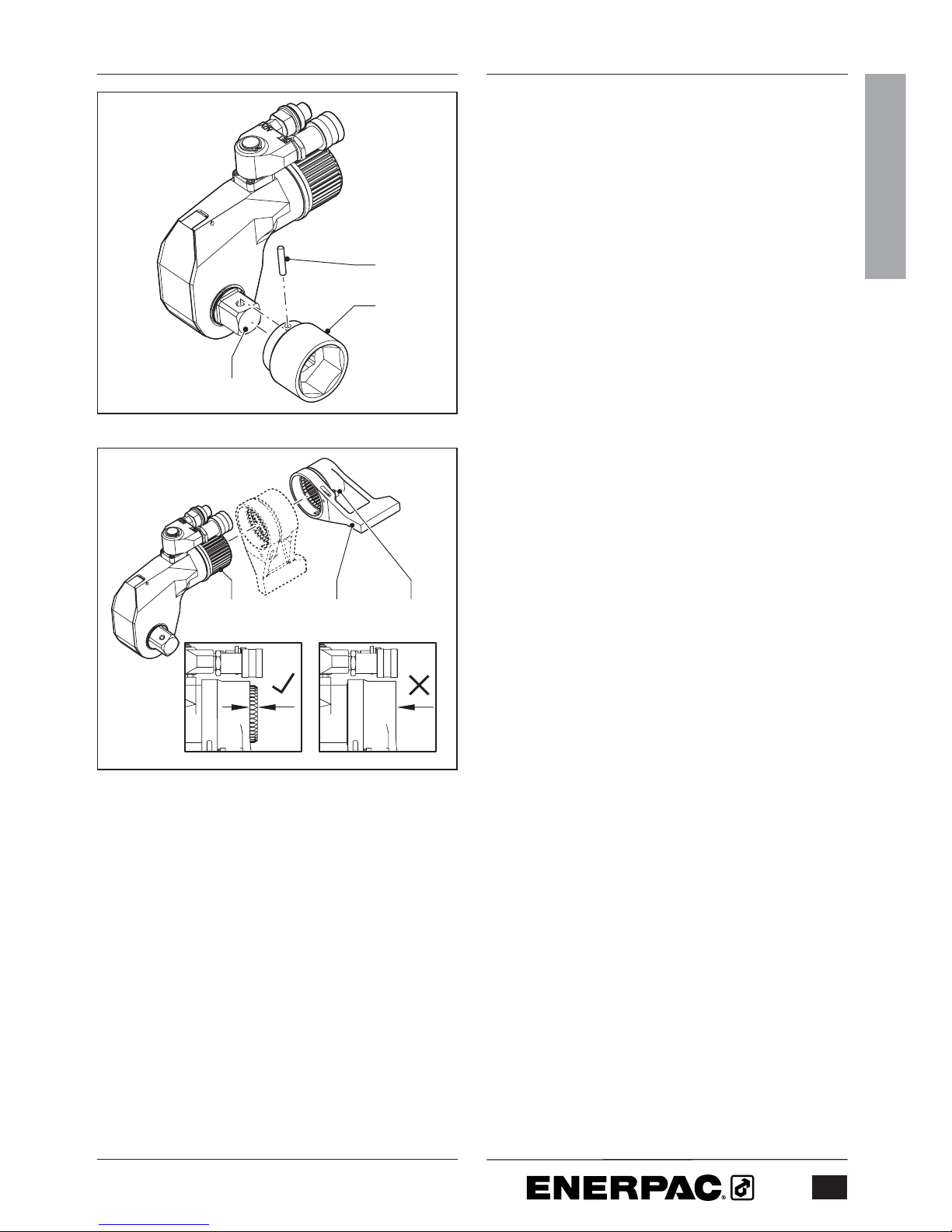
3.5 To mount the reaction arm (fig. D)
The reaction arm can be rotated through
360
o
for maximum stability against a
reaction point.
• Position the reaction arm (6) onto the
ratchet end (11) of the tool.
• Press the latch (7) and slide the arm
all the way onto the tool. Release the
latch to secure the arm.
• To adjust the angle of the reaction
arm (6), press the latch (7) and slide
the arm off the tool. Position the arm
as necessary.
Fig. D
1
10
9
11
76
Page 8

8
ENGLISH
3.6 To connect the hoses (fig. E)
Make sure all accessories meet the
pressure requirements.
Make sure the quick connect
couplings are securely attached
before operating the tool.
The tool is fitted with male and female
quick-connect couplings. Use Enerpac
twin safety hoses only. Refer to the table
below.
Hose model number Description
THQ-706T Two hoses, length
6 m (19.5 feet)
THQ-712T Two hoses, length
12 m (39 feet)
• Remove the hose dust caps.
• Connect the hose with the female
coupling (12) to the advance coupling
(4).
• Pull the sleeve on the female coupling
of the hose over the advance
coupling.
• Tighten the sleeve.
• Connect the hose with the male
coupling (13) into the return coupling
(5).
• Pull the sleeve on the return coupling
over the male coupling of the hose.
• Tighten the sleeve.
• Fit the hoses to the pump. Refer to
the pump instruction manual.
5
4
12
13
Fig. E
Page 9

ENGLISH
9
4 Operation
4.1 Prior to operation
- Make sure the nut or bolt to be
fastened are clean and free of dust.
- Make sure the nut or bolt runs
correctly on the thread.
- Make sure that the threads and the
bearing surface are liberally coated
with the correct lubricant or antiseizure compound.
- Make sure that the spanner used to
keep the nut or bolt on the opposite
end in place, is of the correct size and
that there is an adequate abutment
surface.
- Contact Enerpac if a suitable reaction
point is not available. Enerpac has
extensive experience with providing
special reaction devices.
4.2 To set the torque
Adjust the pressure on the pump as
necessary to set the torque. For a
complete list of torque settings, refer to
the table in the back of the manual.
4.3 To operate the tool (fig. F)
• Position the reaction foot (6) against
a suitable reaction point (14).
The reaction point will counteract the
force caused by operating the tool.
• Start the pump.
• Operate the tool to tighten or loosen
the nut or bolt.
• Stop the pump immediately after
work has finished.
Do not strike the tool, socket or nut
with a hammer while under a full load.
14 6
Fig. F
Page 10

10
ENGLISH
4.3.1 To tighten a nut or bolt (fig. G)
• Position the tool on the nut or bolt in
the orientation as shown.
• Operate the pump until the nut or bolt
has been tightened to the required
torque.
4.3.2 To loosen a nut or bolt (fig. H)
• Apply releasing oil to the threads.
Allow the oil to soak.
• Position the tool on the nut or bolt in
the orientation as shown.
• Operate the pump until the nut or bolt
is loose.
If the nut or bolt will be re-used avoid
excess load when loosening.
Use the tool to take the load off the
nut or bolt only.
For fully threaded UNC nuts or bolts
do not exceed one and a half times
nominal torque for a coefficient of
friction of 0.1.
- Be aware that when loosening a nut
or bolt more torque is usually required
than when tightening.
- Humidity corrosion (rust) requires up
to twice the torque required for
tightening.
- Sea water and chemical corrosion
requires up to two and a half times
the torque required for tightening.
- Heat corrosion requires up to three
times the torque required for
tightening.
Be aware that when loosening a nut
or bolt shock loading can occur.
Do not apply more than 75% of the
maximum torque when loosening nuts
or bolts.
Fig. H
Fig. G
Page 11

ENGLISH
11
5 Maintenance and troubleshooting
Preventative maintenance can be
carried out by the user. Full
maintenance must be carried out by
an approved and authorized
technician appointed by Enerpac.
- Non destructive testing must be
carried out if the tool has been used
under severe conditions.
5.1 Preventative Maintenance (fig. I & J)
• Remove the drive shaft
• Remove the housing guard screws
and remove the housing guard.
• Release the crank pin (16) from the
piston rod hook.
• Remove the crank assembly (17).
• Remove the ratchet (18), spring
loaded drive shoe (19), and
compression springs (20).
• Clean all exposed components with a
mild solvent.
• Inspect all parts for damage.
• Dry all components. Apply a thin coat
of molybdenum disulphide as
indicated (15).
Molybdenum disulphide is available
from Enerpac.
• Reassemble the components in
reverse order except the housing
guard. Make sure that the crank, drive
shoe, ratchet, and crank pin are
correctly installed. Failure to install
these parts correctly will result in
component damage.
• Connect the tool to the pump.
• Check the tool at a nominal pressure
to make sure the piston advances and
retracts freely.
• Release the pressure and make sure
the piston fully retracts.
• Attach the housing guard.
Fig. I
15
15
15
20
19
18
17 16 22 23 21
Fig. J
Page 12

5.2 Full maintenance
5.2.1 Piston removal (fig. J)
• Remove all components as described
for preventative maintenance.
• Remove the circlip from the swivel
coupling.
• Remove the swivel-coupling block
from the tool.
• Remove the pin by removing the pin
retaining screws.
• Remove all ‘O’ rings from the pin and
block.
• Carefully hold the cylinder body to
unscrew the cylinder gland.
• Loosen and remove the piston
locknut (21) using a socket spanner.
To prevent the piston from rotating,
you may temporarily replace the crank
(17).
• Remove the piston rod (22) from the
front of the tool.
• Remove the piston (23) by pushing a
suitable drift through the front of the
tool onto the piston.
• Remove the seals from the piston,
piston locknut and gland.
5.2.2 Cylinder bush removal (fig. K)
(S1500/S3000/S6000/S11000 only)
Only remove the cylinder bush if there
is hydraulic fluid leakage in the head
area.
• Press the retaining ring (24) radially
inward using a flat-head screwdriver.
• Lift the ring away from the groove and
out of the bore using a seal pick.
• The ring end must be positioned at
the slot in the bush for the seal pick
to locate under the bush. If the ring
end is not at the slot, use the
screwdriver to rotate the ring.
12
ENGLISH
242524
Fig. K
Page 13

• Remove the cylinder bush (25) by
pushing a suitable drift through the
front of the tool onto the bush.
• Remove both bush seals.
5.2.3 Reaction arm removal
Only remove the reaction arm if the
retainer is visibly damaged.
• Loosen the set screw.
• Remove the lever/pin and the retainer.
5.2.4 Drive shaft release button removal
Only remove the drive shaft release
button if it is damaged.
• Remove the retaining ring.
• Remove the button circlip.
• Remove the retaining bush.
• Clean all exposed components with a
mild solvent.
• Inspect all parts for damage.
5.2.5 Non Destructive Testing
• Carry out non destructive testing by
magnetic particle inspection on the
following components:
- Body
- Reaction arm
- Crank
- Drive shaft
- Ratchet
- Drive shoe
ENGLISH
13
5.2.6 Reassembly
• Dry all components. Apply a thin coat
of molybdenum disulphide as
indicated (15).
• Lubricate all seals with silicon grease
and reassemble in the reverse order.
• Insert the piston squarely in the bore.
• Apply Loctite 222 to the following
components:
- Swivel coupling pin retaining bolts
- Reaction arm retaining set screw
- Piston locknut threads
• Restrain the hook end of the piston
rod using the crank (17). Tighten the
locknut to the following torque.
Torque
(Nm) (Ft.lbs)
S1500 41 30
S3000 54 40
S6000/S11000 81 60
S25000 81 60
Page 14

5.3 Trouble shooting
Symptom Cause Remedy
Cylinder does not advance or retract Quick-connect coupling Replace the coupling
is damaged
Quick connect- coupling is Reconnect the hoses
not connected and couplings securely
Dirt in the direction control valve Disassemble the unit and
on the pumping unit clean the valve
Cylinder does not build up pressure Piston seal leaks Replace the seals
Pump does not build up pressure Adjust the pressure
Pump is defective Refer to the pump manual
Cylinder leaks Seal failure Replace the cylinder seals
Cylinder operates backwards Connections are reversed Reconnect the hoses
Ratchet returns on retract stroke Broken drive shoe Replace the drive shoe
Ratchet does not take Defective drive shoe Replace the drive shoe
successive strokes Lubricant on the ratchet Disassemble the head and
and/or drive shoe splines remove the lubricant
from splines
14
ENGLISH
Page 15

6 Technical specifications
6.1 Capacities and dimensions (fig. L)
S1500 S3000 S6000 S11000 S25000
Drive shaft inch 3/4 1 1 1/2 1 1/2 2 1/2
Socket capacity mm 15 - 50 20 - 100 41 - 155 41 - 155 60 - 255
inch 5/8 - 1 7/8 7/8 - 3 7/8 1 5/8 - 6 1/4 1 5/8 - 6 1/4 2 3/8 - 10
Maximum operating pressure bar 690 690 690 690 690
psi 10,000 10,000 10,000 10,000 10,000
Max. torque at 690 bar Nm 1.898 4.339 8.144 14.914 34.098
at 10,000 psi Ft.lbs 1,400 3,200 6,010 11,000 25,150
Min. torque at 69 bar Nm 190 434 814 1.491 3.410
at 1000 psi Ft.lbs 140 320 601 1,100 2,515
Dimensions A mm (inch) 39 (1.53) 48 (1.88) 57 (2.24) 71 (2.79) 87 (3.43)
B mm (inch) 63 (2.48) 77 (3.03) 90 (3.54) 111 (4.37) 143 (5.63)
C mm (inch) 110 (4.33) 134 (5.27) 179 (7.04) 196 (7.71) 244 (9.61)
D mm (inch) 95 (3.74) 126 (4.96) 162 (6.37) 185 (7.28) 240 (9.45)
E mm (inch) 136 (5.35) 172 (6.77) 201 (7.91) 226 8.89) 292 (11.50)
F mm (inch) 25,0 (.98) 33,0 (1.29) 42,0 (1.65) 49,5 (1.94) 63,5 (2.50)
G mm (inch) 69 (2.72) 90 (3.54) 112 (4.41) 132 (5.20) 182 (7.17)
H mm (inch) 119 (4.69) 159 (6.26) 187 (7.36) 227 (8.94) 292 (11.50)
Weight kg (lbs) 2,7 (5.94) 5,0 (11.0) 8,5 (18.7) 15,0 (33.0) 31,0 (68.4)
A
F
D
B
C H
G
E
Fig. L
ENGLISH
15
Page 16

16
ENGLISH
6.2 Torque settings
To set the torque, adjust the pump pressure according to the following calculation:
- Pump pressure = Torque / Torque factor
Torque factor
S1500 S3000 S6000 S11000 S25000
Metric system 2,753 6,293 11,818 21,631 49,417
Imperial system 0.14 0.32 0.601 1.1 2.515
Page 17

ENGLISH
17
6.2.1 Metric system table
S1500 S3000 S6000 S11000 S25000
Pump pressure (bar) Torque (Nm) Torque (Nm) Torque (Nm) Torque (Nm) Torque (Nm)
69 190 434 814 1.491 3.410
83 228 520 977 1.789 4.132
97 266 607 1.140 2.087 4.821
110 304 694 1.303 2.385 5.510
124 341 780 1.466 2.683 6.199
138 379 867 1.629 2.981 6.887
152 417 954 1.792 3.279 7.576
166 455 1.041 1.955 3.577 8.265
179 493 1.127 2.117 3.875 8.954
193 531 1.214 2.280 4.173 9.642
207 569 1.301 2.443 4.472 10.331
221 607 1.388 2.606 4.770 11.020
234 645 1.474 2.769 5.068 11.709
248 683 1.561 2.932 5.366 12.397
262 721 1.648 3.095 5.664 13.086
276 759 1.734 3.258 5.962 13.775
290 797 1.821 3.420 6.260 14.464
303 835 1.908 3.583 6.558 15.152
317 873 1.995 3.746 6.856 15.841
331 911 2.081 3.909 7.154 16.530
345 949 2.168 4.072 7.453 17.219
359 986 2.255 4.235 7.751 17.907
372 1.024 2.341 4.398 8.049 18.596
386 1.062 2.428 4.561 8.347 19.285
400 1.100 2.515 4.724 8.645 19.973
414 1.138 2.602 4.886 8.943 20.662
428 1.176 2.688 5.049 9.241 21.351
441 1.214 2.775 5.212 9.539 22.040
455 1.252 2.862 5.375 9.837 22.728
469 1.290 2.948 5.538 10.135 23.417
483 1.328 3.035 5.701 10.434 24.106
497 1.366 3.122 5.864 10.732 24.795
510 1.404 3.209 6.027 11.030 25.483
524 1.442 3.295 6.189 11.328 26.172
538 1.480 3.382 6.352 11.626 26.861
552 1.518 3.469 6.515 11.924 27.550
566 1.556 3.556 6.678 12.222 28.238
579 1.593 3.642 6.841 12.520 28.927
593 1.631 3.729 7.004 12.818 29.616
607 1.669 3.816 7.167 13.116 30.305
621 1.707 3.902 7.330 13.415 30.993
634 1.745 3.989 7.492 13.713 31.682
648 1.783 4.076 7.655 14.011 32.371
662 1.821 4.163 7.818 14.309 33.060
676 1.859 4.249 7.981 14.607 33.748
690 1.897 4.336 8.144 14.905 34.098
Page 18

18
ENGLISH
6.2.2 Imperial system table
S1500 S3000 S6000 S11000 S25000
Pump pressure (psi) Torque Torque Torque Torque Torque
(Ft.lbs) (Ft.lbs) (Ft.lbs) (Ft.lbs) (Ft.lbs)
1,000 140 320 601 1,100 2,515
1,200 168 384 721 1,320 3,048
1,400 196 448 841 1,540 3,556
1,600 224 512 962 1,760 4,064
1,800 252 576 1,082 1,980 4,572
2,000 280 640 1,202 2,200 5,080
2,200 308 704 1,322 2,420 5,588
2,400 336 768 1,442 2,640 6,096
2,600 364 832 1,563 2,860 6,604
2,800 392 896 1,683 3,080 7,112
3,000 420 960 1,803 3,300 7,620
3,200 448 1,024 1,923 3,520 8,128
3,400 476 1,088 2,043 3,740 8,636
3,600 504 1,152 2,164 3,960 9,144
3,800 532 1,216 2,284 4,180 9,652
4,000 560 1,280 2,404 4,400 10,160
4,200 588 1,344 2,524 4,620 10,668
4,400 616 1,408 2,644 4,840 11,176
4,600 644 1,472 2,765 5,060 11,684
4,800 672 1,536 2,885 5,280 12,192
5,000 700 1,600 3,005 5,500 12,700
5,200 728 1,664 3,125 5,720 13,208
5,400 756 1,728 3,245 5,940 13,716
5,600 784 1,792 3,366 6,160 14,224
5,800 812 1,856 3,486 6,380 14,732
6,000 840 1,920 3,606 6,600 15,240
6,200 868 1,984 3,726 6,820 15,748
6,400 896 2,048 3,846 7,040 16,256
6,600 924 2,112 3,967 7,260 16,764
6,800 952 2,176 4,087 7,480 17,272
7,000 980 2,240 4,207 7,700 17,780
7,200 1,008 2,304 4,327 7,920 18,288
7,400 1,036 2,368 4,447 8,140 18,796
7,600 1,064 2,432 4,568 8,360 19,304
7,800 1,092 2,496 4,688 8,580 19,812
8,000 1,120 2,560 4,808 8,800 20,320
8,200 1,148 2,624 4,928 9,020 20,828
8,400 1,176 2,688 5,048 9,240 21,336
8,600 1,204 2,752 5,169 9,460 21,844
8,800 1,232 2,816 5,289 9,680 22,352
9,000 1,260 2,880 5,409 9,900 22,860
9,200 1,288 2,944 5,529 10,120 23,368
9,400 1,316 3,008 5,649 10,340 23,876
9,600 1,344 3,072 5,770 10,560 24,384
9,800 1,372 3,136 5,890 10,780 24,892
10,000 1,400 3,200 6,010 11,000 25,150
Page 19

ENGLISH
19
7 Recommended spare parts
7.1 To order spare parts
Quote the information below when
ordering spare parts:
- The assembly name and serial
numbers.
- The component name and part
number.
- The contract number or
approximate date of purchase.
All item numbers quoted below refer to the
repair parts sheets. For specific
component part numbers refer to the
appropriate bill of materials.
7.2 Seal kit (item 3.0)
- 1 Gland ‘O’ ring
- 1 Piston ‘T’ Seal
- 1 Piston locknut ‘O’ ring - small
- 1 Piston locknut ‘ O’ ring - large
- 1 Rod ‘T’ seal
- 1 Body bush ‘O’ ring
- 2 Swivel manifold pin face ‘O’ rings
- 1 Swivel manifold pin ‘O’ ring
- 2 Swivel manifold block ‘O’ rings
- 1 Manifold retaining clip
7.3 Swivel manifold seal kit (item 2.0)
- 2 Swivel manifold pin face ‘O’ rings
- 1 Swivel manifold pin ‘O’ ring
- 2 Swivel manifold block ‘O’ rings
- 1 Manifold retaining clip
7.4 Spares kit (item 4.0)
- 1 Male coupling
- 1 Female coupling
- 1 Male adaptor
- 1 Body bush retaining ring
- 1 Guard screw (model S1500)
- 2 Guard screws (model S3000)
- 3 Guard screws
(model S6000/S11000/S25000)
- 1 Manifold retaining circlip
- 4 Swivel manifold pin retaining
screws
- 1 Crank pin
- 2 Drive shoe springs
- 1 Reaction arm retainer screw
- 1 Reaction arm retainer spring
- 1 Guard pin (S1500 only)
- 1 Drive shaft holder retaining ring
7.5 Drive shaft button kit (item 1.13)
7.6 Recommended tool kit
S1500
- 1 7/8” spanner
- 1 3/4” spanner
- 1 5/8” spanner
- 1 Circlip pliers
- 1 Seal extraction tool
- 1 14 mm socket
- 1 ø 4 x 20 mm PCD pin spanner
- 1 1,5 mm Allen key
- 1 2 mm Allen key
- 1 2,5 mm Allen key
- 1 3 mm Allen key
Page 20

20
ENGLISH
S3000
- 1 7/8” spanner
- 1 3/4” spanner
- 1 5/8” spanner
- 1 Circlip pliers
- 1 Seal extraction tool
- 1 20 mm socket
- 1 ø 4 x 25 mm PCD pin spanner
- 1 1,5 mm Allen key
- 1 2,5 mm Allen key
- 1 3 mm Allen key
S6000
- 1 7/8” spanner
- 1 3/4” spanner
- 1 5/8” spanner
- 1 Circlip pliers
- 1 Seal extraction tool
- 1 22 mm socket
- 1 ø 4 x 30 mm PCD pin spanner
- 1 1,5 mm Allen key
- 1 2,5 mm Allen key
- 1 4 mm Allen key
S11000
- 1 7/8” spanner
- 1 3/4” spanner
- 1 5/8” spanner
- 1 Circlip pliers
- 1 Seal extraction tool
- 1 26 mm socket
- 1 ø 4 x 40 mm PCD pin spanner
- 1 1,5 mm Allen key
- 1 3 mm Allen key
- 1 4 mm Allen key
S25000
- 1 7/8” spanner
- 1 3/4” spanner
- 1 5/8” spanner
- 1 Circlip pliers
- 1 Seal extraction tool
- 1 36 mm socket
- 1 ø 5 x 60 mm PCD pin spanner
- 1 1,5 mm Allen key
- 1 3 mm Allen key
- 1 4 mm Allen key
Page 21

Please contact Enerpac if the CD is not included,
or visit www.enerpac.com for a download of the manual.
Page 22

Africa
ENERPAC Middle East FZE
P.O. Box 18004
Jebel Ali, Dubai
United Arab Emirates
Tel: +971 (0)4 8872686
Fax: +971 (0)4 8872687
Australia
Actuant Australia Ltd.
Block V Unit 3
Regents Park Estate
391 Park Road
Regents Park NSW 2143
(P.O. Box 261) Australia
Tel: +61 297 438 988
Fax: +61 297 438 648
Brazil
Power Packer do Brasil Ltda.
Rua dos Inocentes, 587
04764-050 - Sao Paulo (SP)
Tel: +55 11 5687 2211
Fax: +55 11 5686 5583
Toll Free in Brazil:
Tel: 0800 891 5770
vendasbrasil@enerpac.com
Canada
Actuant Canada Corporation
6615 Ordan Drive, Unit 14-15
Mississauga, Ontario L5T 1X2
Tel: +1 905 564 5749
Fax: +1 905 564 0305
Toll Free:
Tel: +1 800 268 4987
Fax: +1 800 461 2456
Technical Inquiries:
techservices@enerpac.com
China
Actuant China Ltd.
1F, 269 Fute N. Road
Waigaoqiao Free Trade Zone
Pudong New District
Shanghai, 200 131 China
Tel: +86 21 5866 9099
Fax: +86 21 5866 7156
Actuant China Ltd. (Beijing)
709A Xin No. 2
Diyang Building
Dong San Huan North Rd.
Beijing City
100028 China
Tel: +86 10 845 36166
Fax: +86 10 845 36220
Central and Eastern Europe
ENERPAC B.V.
Galvanistraat 115
P.O. Box 8097
6710 AB Ede
The Netherlands
Tel: +31 318 535 936
Fax: +31 318 535 951
France
ENERPAC
Une division de ACTUANT
France S.A.
B.P. 200, Parc d’Activités
du Moulin de Massy
F-91882 Massy CEDEX France
Tel: +33 1 601 368 68
Fax: +33 1 692 037 50
Germany, Austria, Greece
and Switzerland
ENERPAC GmbH
P.O. Box 300113
D-40401 Düsseldorf
Germany
Tel: +49 211 471 490
Fax: +49 211 471 49 28
India
ENERPAC Hydraulics
(India) Pvt. Ltd.
Office No. 9,10 & 11,
Plot No. 56, Monarch Plaza,
Sector 11, C.B.D. Belapur
Navi Mumbai 400614, India
Tel: +91 22 2756 6090
Tel: +91 22 2756 6091
Fax: +91 22 2756 6095
Italy
ENERPAC S.p.A.
Via Canova 4
20094 Corsico (Milano)
Tel: +39 02 4861 111
Fax: +39 02 4860 1288
Japan
Applied Power Japan Ltd.
1-1-11, Shimomae
Toda-shi
Saitama Pref.
Japan 335-0016
Tel: +81 484 30 1055
Fax: +81 484 30 1066
Middle East, Turkey and
Caspian Sea
ENERPAC Middle East FZE
P.O. Box 18004
Jebel Ali, Dubai
United Arab Emirates
Tel: +971 (0)4 8872686
Fax: +971 (0)4 8872687
Russia and CIS
(excl. Caspian Sea Countries)
Actuant LLC
Admiral Makarov Street 8
125212 Moscow, Russia
Tel: +7-095-9809091
Fax: +7-095-9809092
Singapore
Actuant Asia Pte. Ltd.
25 Serangoon North Ave. 5
#03-01 Keppel Digihub
Singapore 554914
Thomson Road
P.O. Box 114
Singapore 915704
Tel: +65 64 84 5108
+65 64 84 3737
Fax: +65 64 84 5669
Toll Free:
Tel: +1800 363 7722
Technical Inquiries:
techsupport@enerpac.com.sg
South Korea
Actuant Korea Ltd.
3Ba 717,
Shihwa Industrial Complex
Jungwang-Dong, Shihung-Shi,
Kyunggi-Do
Republic of Korea 429-450
Tel: +82 31 434 4506
Fax: +82 31 434 4507
Spain and Portugal
ENERPAC
C/San José Artesano 8
Pol. Ind.
28108 Alcobendas
(Madrid) Spain
Tel: +34 91 661 11 25
Fax: +34 91 661 47 89
The Netherlands, Belgium,
Luxembourg, Sweden,
Denmark, Norway, Finland
and Baltic States
ENERPAC B.V.
Galvanistraat 115
P.O. Box 8097, 6710 AB Ede
The Netherlands
Tel: +31 318 535 911
Fax: +31 318 525 613
+31 318 535 848
Technical Inquiries Europe:
techsupport.europe@enerpac.com
United Kingdom, Ireland
ENERPAC Ltd., P.O. Box 33
New Romney, TN28 8QF
United Kingdom
Tel: +44 1527 598 900
Fax: +44 1527 585 500
USA, Latin America
and Caribbean
ENERPAC
P.O. Box 3241
6100 N. Baker Road
Milwaukee, WI 53209 USA
Tel: +1 262 781 6600
Fax: +1 262 783 9562
User inquiries:
+1 800 433 2766
Distributor inquiries/orders:
+1 800 558 0530
Technical Inquiries:
techservices@enerpac.com
Hydraulic Technology Worldwide
e-mail: info@enerpac.com
Internet: www.enerpac.com
© 2005 Enerpac - Subjects to change without notice.
 Loading...