


POWERFUL SOLUTIONS. GLOBAL FORCE.
Instruction and
Repair Parts Sheet
BHP Puller Sets
and Attachments
EIS 65.100-1 05/14 Rev. F
index:
English Instruction Sheet............................................................. |
pages............. |
1-4 |
Repair Parts Sheet....................................................................... |
pages........... |
5-12 |
Française Notice d’Emploi........................................................... |
pages......... |
13-16 |
Deutsche Bedienungsanleitung................................................... |
Seiten ........ |
17-20 |
Italiano Manuale Istruzioni........................................................... |
pagine........ |
21-24 |
Español Instrucciones ................................................................. |
páginas ...... |
25-28 |
Nederlandse Gebruikershandleiding....................................... |
blz............. |
29-32 |
Русская инструкция ................................................................. |
страница..... |
33-36 |
|
|
|
1.0 IMPORTANT RECEIVING INSTRUCTIONS
Visually inspect all components for shipping damage. Shipping damage is not covered by warranty. If shipping damage is found notify carrier at once. The carrier is responsible for all repair and replacement costs resulting from damage in shipment.
SAFETY FIRST
Read all instructions, warnings and cautions carefully. Follow all safety precautions to avoid personal injury or property damage during system operation. Enerpac cannot be responsible for damage or injury resulting from unsafe use of product, lack of maintenance or incorrect product and/or system operation. Contact Enerpac when in doubt as to the safety precautions and applications. TO PROTECT YOUR WARRANTY, USE ONLY ENERPAC HYDRAULIC OIL.
2.0 PRODUCT DESCRIPTION
Enerpac BHP-series puller sets consist basically of a handpump, single-acting cylinder, gauge, gauge adaptor, hose, couplers and specific tools and attachments. The pullers are designed for installing and removing all press fitted and heat fitted parts such as gears, pulleys, wheels, bearings, sleeves, sprockets, pins and other stubborn parts.
The Enerpac BHP-series puller sets are available as: Grip Puller Sets (see paragraph 2.1), Cross-Bearing Puller Sets (see paragraph 2.2) and Multi-Purpose Puller Sets (see paragraph 2.3).
Puller set attachments are additional parts to increase on-the-job flexibility further with the use of grip pullers and cross-bearing pullers. See tables D and E on the pages 11 and 12 for the individual components of puller set attachments.
2.1 Grip Puller Sets
The grip puller sets BHP-152, BHP-251G, BHP-351G and BHP-551G can be used to remove and install gears, bearings, pulleys and similar parts. See illustration 1 on page 3: grip pullers can be used with a double crosshead (2 grip arms) or a triple crosshead (3 grip arms). For individual parts see table A on page 7.
2.2 Cross Bearing Puller Sets
The cross bearing puller sets BHP-162, BHP-261G, BHP-361G and BHP-561G can be used to remove and install gears, pulleys, sleeves and bushings. These pullers can also be used as bearing cup pullers (internal grip pullers) as shown in illustr. 2 on page 3 or as bearing pullers as shown in illustration 3 on page 3.
In situations where clearance prevents a direct application of grip puller arms, it is possible to use the puller in combination with bearing puller attachment as shown in illustration 4 on page 4. Bearing puller attachments have wedge shaped edges to place the puller behind the hard to reach the gear or bearing. See table B on page 9 for individual components.
1

2.3 Multi-Purpose Puller Sets
BHP-1752, BHP-2751G, BHP-3751G and BHP-5751G multi-purpose puller sets are a combination of the above mentioned grip puller sets and cross bearing puller sets to provide maximum application flexibility in pulling and pushing applications in maintenance and repair. See table C (page 10) for individual components.
3.0 GENERAL SAFETY ISSUES
Failure to comply with the following cautions and warnings could cause equipment damage or personal injury.
WARNING: DO NOT exceed 50% of the rated puller capacity when using a double crosshead (2 grip arms): do not exceed 350 bar (5,000 psi) when using a hydraulic puller in this application.
WARNING: DO NOT exceed 50% of the rated puller capacity when using the puller legs in combination with bearing puller attachment: do not exceed 350 bar (5,000 psi) when using a hydraulic puller in this application.
IMPORTANT: It is recommended to use the triple crosshead (3 grip arms) which gives a more secure grip, a more even pulling force and is more stable than the double crosshead (2 grip arms).
WARNING: To avoid personal injury and equipment damage, make sure all hydraulic components withstand the max. hydraulic pressure of 700 bar (10,000 psi).
IMPORTANT: Use hydraulic gauges in each hydraulic system to indicate safe operating loads.
WARNING: Make sure that all system components are protected from external sources of damage, such as excessive heat, flame, moving machine parts, sharp edges and corrosive chemicals.
CAUTION: Avoid sharp bends and kinks that which will cause severe back-up pressure in hoses. Bends and kinks lead to premature hose failure.
WARNING: DO NOT handle pressurized hoses. Escaping oil under pressure can penetrate the skin causing serious injury. If oil is injected under the skin see a doctor immediately.
WARNING: The operator must take precaution against injury due to flying debris caused by failure of the tool or workpiece.
WARNING: DO NOT use this equipment in circumstances where a sudden release of pressure can result in loss of balance causing damage or injury.
WARNING: DO NOT overload equipment. Use the right size puller. When you have applied maximum force, but the part will not move, go to a larger capacity puller. Resist sledging.
IMPORTANT: It is impossible to predict the exact force needed for every pulling situation. The amount of press fit and force of removal can vary greatly between
jobs. Set-up requirements along with the size, shape and condition of the parts being pulled are variables which must be considered. Study each pulling application before you select your puller.
IMPORTANT: Apply force gradually. Align puller legs and grip arms. Be sure the setup is rigid and puller is square with the work.
WARNING: Immediately replace worn or damaged parts with genuine Enerpac parts. Enerpac parts are designed to fit properly and withstand rated loads.
4.0INSTALLATION
4.1Grip pullers
Illustration 5 on page 6 shows how to build-up your grip puller. The numbers in illustration 5 correspond with the parts numbered in table A on page 7.
4.2 Cross bearing pullers
Illustration 6 on page 8 shows how to build-up your cross bearing puller. The numbers in illustration 6 correspond with the parts numbered in table B on page 9.
4.3 Internal pullers
Illustration 7 on page 8 shows how to build-up your internal puller. The numbers in illustr. 7 correspond with the parts numbered in table B on page 9.
2

5.0 OPERATION
IMPORTANT: It is mandatory that the operator has a full understanding of all instructions, safety regulations, cautions and warnings, before starting to operate
any of this high force tool equipment. When in doubt, contact Enerpac.
5.1 Advancing and retracting the cylinder
All BHP Puller Sets are equipped with a singleacting, spring return cylinder and a handpump. For complete operating instructions refer to the instruction sheet included with each pump and cylinder.
Handpumps to operate single-acting cylinders are equipped with a release valve to release pressure. Close the release valve, raise and lower the pump handle to advance the cylinder. To retract the cylinder, open the release valve.
5.2 Air removal
Advance and retract the cylinder several times avoiding pressure build-up. Air removal is complete when the cylinder motion is smooth.
5.3 Using grip pullers
Build up your application as shown in illustr. 1 below and illustration 5 on page 6. Remember that the triple grip puller provides a more stable and secure grip, with a more even pulling force than the double grip puller. Do not exceed 50% of the rated puller capacity with a double grip puller. Start pumping and apply hydraulic pressure gradually to remove the part.
illustration 1 - Grip Pullers
Removing pulley with |
Removing pulley with |
2-jaw grip puller |
3-jaw grip puller |
(double crosshead) |
(triple crosshead) |
Do not exceed |
|
50% of rated |
|
capacity. |
|
5.4 Using bearing cup puller
Build up your application as shown in illustration 2 with the internal grip puller. See also illustr. 7 page 8. Align puller legs and arms and apply hydraulic pressure gradually to remove the part.
illustration 2 - Crosshead puller with bearing cup puller attachment 

Do not 

 exceed 50% of rated capacity.
5.5 Using cross bearing pullers
To pull: The cylinder must be positioned above the slotted crosshead. Align puller legs and adjusting screw and apply hydraulic pressure gradually to remove the part.
To push: Build up the application as shown in illustration 3. Notice that the cylinder must be positioned under the slotted crosshead. Align puller legs and adjusting screw and apply hydraulic pressure gradually to remove the part.
illustration 3 - Pushing with cross bearing puller
Do not 

 exceed 50% of rated capacity.
3

5.6 Using bearing puller attachment
The bearing puller attachment can be used in combination with the crosshead puller shown in the illustration 4 below and illustration 6 on page 8.
illustration 4 - Bearing puller attachment with Crosshead Puller
Do not 

 exceed 50% of rated capacity.
6.0 MAINTENANCE AND SERVICE
Maintenance is required when wear or leakage is noticed. Periodically inspect all components to detect any problem requiring service and maintenance.
Enerpac offers ready-to-use spare parts kits for repair and/or replacements. Contact Enerpac.
IMPORTANT: Hydraulic equipment must be serviced by a qualified hydraulic technician. For repair service, contact the Authorized Enerpac Service Center in your area.
•Periodically inspect all components to detect any problem requiring maintenance and service. Replace damaged parts immediately.
•Do not exceed oil temperature of 60˚C [140˚F].
•Keep all hydraulic components clean.
•Keep your pulling equipment in shape. Clean and lubricate the puller’s adjusting screw and puller legs frequently, from thread to tip, to ensure good operation and long life.
•Periodically check the hydraulic system for loose connections and leaks.
•Change hydraulic oil in your system as recommended in the pump instruction sheet.
4

Repair Parts Sheet
BHP Puller Sets
and Attachments
Note: See pages 6 through 12 for repair parts lists and diagrams.
Hinweis: Siehe Seiten 6 bis 12 für Ersatzteillisten und Schemata.
Nota: Véanse las páginas 6-12 para las listas de piezas de recambio y diagramas.
Remarque : Voir les pages 6 -12 pour les listes des pièces de rechange et les schémas. Nota: Per consultare i diagrammi e gli elenchi dei pezzi di ricambio, fare riferimento alle pagine 6 - 12.
N.B.: Zie pagina's 6 tot en met 12 voor reparatielijsten en schema's. Замечание: См. стр. 6-12 для запасных частей и схем.
5

illustration 5 - How to set up a Grip Puller. Numbers correspond with table A on page 7.
figure 5 - Comment assembler un extracteur à griffes. Les números correspondent à ceux de la table A page 7. Abbildung 5 - Montieren der Abzugsätze.
Die Zahlen stimmen mit Tabelle A auf Seite 7 überein. figura 5 - Come montare un estrattore a griffe. I numeri corrispondono con quelli della tabella A a pagina 7. ilustración 5 - Modo de colocación de un extractor de garras. Los números corresponden con el cuadro A en la página 7.
illustratie 5 - Opbouwen van Trekkersets met trekarmen. De nummers komen overeen met tabel A op bladzijde 7. Рис. 5. Сборка зажимного съемника. Числа на рисунке соответствуют числам в таблице A (стр. 7).
2 grip arms


 Tête à 2 griffes


 Kreuzkopf 2-armig
Traversa 2 griffe
Cruceta doble
2-armig juk
Зажим с 2 лапами
3 grip arms Tête à 3 griffes
Kreuzkopf 3-armig Traversa 3 griffe Cruceta triple
3-armig juk
Зажим с 3 лапами
Цилиндр
RWH
RWH или RCH or
RCH
Cyl.
12
2
3-4
15

 13+14
13+14
19
17
6

|
Note: Refer to |
|
Illustration 5 |
TABLE A - INDIVIDUAL COMPONENTS OF GRIP PULLER SETS |
(page 6) |
Model Number - Grip Puller Sets |
BHP-152 |
BHP-251G |
BHP-351G |
BHP-551G |
|||
|
|
|
|
|
|
||
Maximum Capacity |
8 ton |
20 ton |
30 ton |
50 ton |
|||
|
|
Pump |
P-142 |
P-392 |
P-392 |
P-80 |
|
|
|
||||||
|
|
|
|
|
|
|
|
Hydraulic |
Cylinder |
RWH-121 |
RCH-202 |
RCH-302 |
RCH-603 |
||
|
|
|
|
|
|||
Components |
|
|
|
|
|
||
|
GF-120P (US) |
GF-813P (US) |
GF-813P (US) |
GF-813P (US) |
|||
|
|
|
|||||
|
|
Gauge |
GF-120B (Eur) |
GF-813B (Eur) |
GF-813B (Eur) |
GF-813B (Eur) |
|
|
|
|
+ GA-4 1) |
+ GA-3 1) |
+ GA-3 1) |
+ GA-3 1) |
|
|
|
Hose |
HB-7206QB |
HC-7206 |
HC-7206 |
HC-7206 |
|
|
|
|
|
|
|
|
|
Weight / Poids |
22 kg |
56 kg |
91 kg |
160 kg |
|||
48 lbs |
123 lbs |
200 lbs |
353 lbs |
||||
|
|
|
|||||
|
|
|
|
|
|
|
|
1 |
Cyl. Adapter |
-- |
-- |
-- |
-- |
||
|
|
|
|
|
|
|
|
2 |
Grip Arms |
HP-1125 (3x) |
HP-2125 (3x) |
HP-3125 (3x) |
HP-5125 (3x) |
||
|
|
|
|
|
|
|
|
3 |
Double Crosshead |
-- |
HP-2120 |
HP-3120 |
HP-5120 |
||
|
|
|
|
|
|
|
|
4 |
Triple Crosshead |
HP-1130 |
HP-2130 |
HP-3130 |
HP-5130 |
||
|
|
|
|
|
|
|
|
12 |
Adjusting Rod |
HP-1111 |
HP-2111 |
HP-3111 |
HP-5111 |
||
|
|
|
|
|
|
|
|
13 |
Strap Nut Kit |
HP-1123 |
HP-2023 |
HP-3123 |
HP-5023 |
||
(Includes 6 nuts) |
|||||||
|
|
|
|
|
|
|
|
14 |
Strap Screw Kit |
HP-1122 |
HP-2122 |
HP-3122 |
HP-5122 |
||
(includes 6 screws) |
|||||||
|
|
|
|
|
|
|
|
15 |
Straps |
HP-1121 (6x) |
HP-2121 (6x) |
HP-3121 (6x) |
HP-5121 (6x) |
||
|
|
|
|
|
|
|
|
17 |
Threaded Saddle |
-- |
HP-2015 |
HP-3015 |
HP-5016 |
||
|
|
|
|
|
|
|
|
19 |
Mounting Screw Kit |
HP-1120 |
HP-2213 |
HP-2013 |
HP-5013 |
||
(includes 2 screws) |
|||||||
|
|
|
|
|
|
|
|
1) GA = Gauge Adaptor
2
3

4
12 
13
14
17 
19
7

illustration 6 - How to set up a Cross Bearing Puller. Numbers correspond with table B on page 9
figure 6 - Comment assembler un extracteur à tirants. Les números correspondent à ceux de la table B page 9. Abbildung 6 - Montieren der Jochabzieher.
Die Zahlen stimmen mit Tabelle B auf Seite 9 überein. figura 6 - Come montare un estrattore a tiranti. I numeri corrispondono con quelli della tabella B a pagina 9. ilustración 6 - Modo de colocación de un extractor de cojinetes. Los números corresponden con el cuadro B en la página 9.
illustratie 6 - Opbouwen van brugstuk-lagertrekkers. De nummers komen overeen met tabel B op bladzijde 9. Рис. 6. Сборка съемника-хомута. Числа на рисунке соответствуют числам в таблице B (стр. 9).
9
12
10
16
5 |
|
18 |
20 |
11 |
|
7 |
RWH / RHC |
|
RWH / RCH |
Цилиндр
17 Cylinder
illustration 7 - How to set up a Internal Puller. Numbers correspond with table B on page 9
figure 7 - Comment assembler un extracteur intérieur. Les números correspondent à ceux de la table B page 9. Abbildung 7 - Montieren der Lagerschalenabzieher. Die Zahlen stimmen mit Tabelle B auf Seite 9 überein. figura 7 - Come montare un estrattore per interni. I numeri corrispondono con quelli della tabella B a pagina 9.
ilustración 7 - Modo de colocación de un extractor interior. Los números corresponden con el cuadro B en la páguina 9.
illustratie 7 - Opbouwen van inwendige lagertrekkers. De nummers komen overeen met tabel B op bladzijde 9. Рис. 7. Сборка съемника с внутренним захватом Числа на рисунке соответствуют числам в таблице B (стр. 9).
RWHRWHили
RCHor
ЦилиндрRCH 12
Cylinder
10
16


 20
20  5
5
18
17
 11
11
6
8
8

TABLE B - INDIVIDUAL COMPONENTS OF CROSS-BEARING PULLER SETS
Cross-Bearing Puller Sets |
BHP-162 |
BHP-261G |
BHP-361G |
BHP-561G |
|||
|
|
|
|
|
|
||
Max. Capacity |
8 ton |
20 ton |
30 ton |
50 ton |
|||
|
|
|
|
|
|
|
|
|
|
Pump |
P-142 |
P-392 |
P-392 |
P-80 |
|
|
|
|
|
|
|
|
|
|
|
Cylinder |
RWH-121 |
RCH-202 |
RCH-302 |
RCH-603 |
|
Hydraulic |
|
|
|
|
|
||
Components |
|
GF-120P (US) |
GF-813P (US) |
GF-813P (US) |
GF-813P (US) |
||
|
|
Gauge |
GF-120B (Eur) |
GF-813B (Eur) |
GF-813B (Eur) |
GF-813 (Eur) |
|
|
|
|
+ GA-4 1) |
+ GA-3 1) |
+ GA-3 1) |
+ GA-3 1) |
|
|
|
Hose |
HB-7206QB |
HC-7206 |
HC-7206 |
HC-7206 |
|
|
|
|
|
|
|
|
|
Weight |
26 kg |
62 kg |
121 kg |
185 kg |
|||
57 lbs |
164 lbs |
267 lbs |
408 lbs |
||||
|
|
|
|||||
|
|
|
|
|
|
|
|
5 |
Slotted Crosshead |
HP-1103 |
HP-2103 |
HP-3104 |
HP-5103 |
||
|
|
|
|
|
|
|
|
6 |
Bearing Cup Pull. |
BHP-180 |
BHP-280 |
BHP-380 |
BHP-580 |
||
|
|
|
|
|
|
|
|
7 |
Bearing Puller |
BHP-181 |
BHP-282 |
BHP-382 |
BHP-582 |
||
|
|
|
|
|
|
|
|
8 |
Leg End Kit |
HP-2009 |
HP-2009 |
HP-3039 |
-- |
||
(includes 2 leg ends) |
|||||||
|
|
|
|
||||
|
|
|
|
|
|
|
|
9 |
Leg Reducer Kit |
HP-2031 |
HP-2031 |
HP-3041 |
-- |
||
(includes 4 reducers) |
|||||||
|
|
|
|
||||
|
|
|
|
|
|
|
|
10 |
Leg Nut Kit |
HP-2001 |
HP-2001 |
HP-3031 |
HP-5001 |
||
(includes 2 nuts) |
|||||||
|
|
|
|
||||
|
|
|
|
|
|
|
|
|
|
|
HP-1136 (2x) |
HP-2006 (2x) |
HP-3036 (2x) |
HP-5007 (2x) |
|
11 |
Leg 2) |
HP-2007 (2x) |
|||||
HP-1137 (2x) |
HP-2008 (2x) |
HP-3037 (2x) |
HP-5008 (2x) |
||||
|
|
|
HP-2012 (2x) |
HP-3038 (2x) |
|||
|
|
|
|
|
|
|
|
12 |
Adjusting Rod |
HP-1111 |
HP-2111 |
HP-3111 |
HP-5111 |
||
|
|
|
|
|
|
|
|
16 |
Slide Plate |
HP-1105 (2x) |
HP-2105 (2x) |
HP-3135 (2x) |
HP-5102 (2x) |
||
|
|
|
|
|
|
|
|
17 |
Threaded Saddle |
-- |
HP-2015 |
HP-3015 |
HP-5016 |
||
|
|
|
|
|
|
|
|
18 |
Washer Kit |
HP-1102 |
HP-2002 |
HP-3032 |
HP-5132 |
||
(includes 2 washers) |
|||||||
|
|
|
|
||||
|
|
|
|
|
|
|
|
20 |
Mounting Screw Kit |
HP-1213 |
HP-2213 |
HP-3113 |
HP-5113 |
||
(includes 2 screws) |
|||||||
|
|
|
|
||||
|
|
|
|
|
|
|
|
1) GA = Gauge Adaptor 2) See Leg Lengths table on page 11 for additional information.
Note: Refer to Illustration 6 or 7 (page 8)
5
6 


7 


8
9
10
11
12
16
17
18
20
9

TABLE C - INDIVIDUAL COMPONENTS OF MULTI-PURPOSE PULLER SETS
Multi-Purpose Puller Sets |
BHP-1752 |
BHP-2751G |
BHP-3751G |
BHP-5751G |
||
|
|
|
|
|
|
|
Capacity |
8 ton |
20 ton |
30 ton |
50 ton |
||
|
|
|
|
|
|
|
|
|
Pump |
P-142 |
P-392 |
P-392 |
P-80 |
|
|
|
|
|
|
|
|
|
Cylinder |
RWH-121 |
RCH-202 |
RCH-302 |
RCH-603 |
Hydraulic |
|
|
|
|
|
|
Components |
Gauge |
GF-120P (US) |
GF-813P (US) |
GF-813P (US) |
GF-813P (US) |
|
|
|
GF-120B (Eur) |
GF-813B (Eur) |
GF-813B (Eur) |
GF-813B (Eur) |
|
|
|
|
+ GA-4 1) |
+ GA-3 1) |
+ GA-3 1) |
+ GA-3 1) |
|
|
Hose |
HB-7206QB |
HC-7206 |
HC-7206 |
HC-7206 |
|
|
|
|
|
|
|
2 |
Grip Arms |
HP-1125 (3x) |
HP-2125 (3x) |
HP-3125 (3x) |
HP-5125 (3x) |
|
|
|
|
|
|
|
|
3 |
Double Crosshead |
-- |
HP-2120 |
HP-3120 |
HP-5120 |
|
|
|
|
|
|
|
|
4 |
Triple Crosshead |
HP-1130 |
HP-2130 |
HP-3130 |
HP-5130 |
|
|
|
|
|
|
|
|
5 |
Slotted Crosshead |
HP-1103 |
HP-2103 |
HP-3104 |
HP-5103 |
|
|
|
|
|
|
|
|
6 |
Bearing Cup Pull. |
BHP-180 |
BHP-280 |
BHP-380 |
BHP-580 |
|
|
|
|
|
|
|
|
7 |
Bearing Puller |
BHP-181 |
BHP-282 |
BHP-382 |
BHP-582 |
|
|
|
|
|
|
|
|
8 |
Leg End Kit |
HP-2009 |
HP-2009 |
HP-3039 |
-- |
|
(includes 2 leg ends) |
||||||
|
|
|
|
|
|
|
9 |
Leg Reducer Kit |
HP-2031 |
HP-2031 |
HP-3041 |
-- |
|
(includes 4 reducers) |
||||||
|
|
|
|
|
|
|
10 |
Leg Nut Kit |
HP-2001 |
HP-2001 |
HP-3031 |
HP-5001 |
|
(includes 2 nuts) |
||||||
|
|
|
|
|
|
|
11 |
|
|
HP-1136 (2x) |
HP-2006 (2x) |
HP-3036 (2x) |
HP-5007 (2x) |
Leg 2) |
HP-2007 (2x) |
|||||
HP-1137 (2x) |
HP-2008 (2x) |
HP-3037 (2x) |
HP-5008 (2x) |
|||
|
|
|
HP-2012 (2x) |
HP-3038 (2x) |
||
|
|
|
|
|
||
12 |
Adjusting Rod |
HP-1111 |
HP-2111 |
HP-3111 |
HP-5111 |
|
|
|
|
|
|
|
|
13 |
Strap Nut Kit |
HP-1123 |
HP-2023 |
HP-3123 |
HP-5023 |
|
(includes 6 nuts) |
||||||
|
|
|
|
|
|
|
14 |
Strap Screw Kit |
HP-1122 |
HP-2122 |
HP-3122 |
HP-5122 |
|
(includes 6 screws) |
||||||
|
|
|
|
|
|
|
15 |
Straps |
HP-1121 (6x) |
HP-2121 (6x) |
HP-3121 (6x) |
HP-5121 (6x) |
|
|
|
|
|
|
|
|
16 |
Slide Plate |
HP-1105 (2x) |
HP-2105 (2x) |
HP-3135 (2x) |
HP-5102 (2x) |
|
|
|
|
|
|
|
|
17 |
Threaded Saddle |
-- |
HP-2015 |
HP-3015 |
HP-5016 |
|
|
|
|
|
|
|
|
18 |
Washer Kit |
HP-1102 |
HP-2002 |
HP-3032 |
-- |
|
(includes 2 washers) |
||||||
|
|
|
|
|
|
|
19 |
Short Mounting Screw Kit |
HP-1120 |
HP-2113 |
HP-2013 |
HP-5013 |
|
(includes 2 screws) |
||||||
|
|
|
|
|
|
|
20 |
Long Mounting Screw Kit |
HP-1213 |
HP-2213 |
HP-3113 |
HP-5113 |
|
(includes 2 screws) |
||||||
|
|
|
|
|
|
|
1) GA = Gauge Adaptor 2) See Leg Lengths table on page 11 for additional information.
Note: Refer to Illustration 5 (page 6) or
illustrations 6 & 7 (page 8)
2
3

4
5
6 


7 


8 
9 
10 
11 
12
13
14
15
16 
17
18
19
20

10
TABLE D - INDIVIDUAL COMPONENTS OF GRIP PULLER ATTACHMENTS
Grip Puller Attachments |
BHP-1762 |
BHP-252 |
BHP-352 |
BHP-552 |
|
|
|
|
|
|
|
Capacity |
8 ton |
20 ton |
30 ton |
50 ton |
|
|
|
|
|
|
|
2 |
Grip Arms |
HP-1125 (3x) |
HP-2125 (3x) |
HP-3125 (3x) |
HP-5125 (3x) |
|
|
|
|
|
|
3 |
Double Crosshead |
-- |
HP-2120 |
HP-3120 |
HP-5120 |
|
|
|
|
|
|
4 |
Triple Crosshead |
HP-1130 |
HP-2130 |
HP-3130 |
HP-5130 |
|
|
|
|
|
|
12 |
Adjusting Rod |
HP-1111 |
HP-2111 |
HP-3111 |
HP-5111 |
|
|
|
|
|
|
13 |
Strap Nut Kit |
HP-1123 |
HP-2023 |
HP-3123 |
HP-5023 |
(includes 6 nuts) |
|||||
|
|
|
|
|
|
14 |
Strap Screw Kit |
HP-1122 |
HP-2122 |
HP-3122 |
HP-5122 |
(includes 6 screws) |
|||||
|
|
|
|
|
|
15 |
Straps |
HP-1121 (6x) |
HP-2121 (6x) |
HP-3121 (6x) |
HP-5121 (6x) |
|
|
|
|
|
|
17 |
Threaded Saddle |
-- |
HP-2015 |
HP-3015 |
HP-5016 |
|
|
|
|
|
|
19 |
Mounting Screw Kit |
HP-1120 |
HP-2213 |
HP-2013 |
HP-5013 |
(includes 2 screws) |
|||||
|
|
|
|
|
|
LEG LENGTHS (See item #11, tables B, C and E)
Leg Part Number |
Leg Length |
Used on Puller Models: |
|
inch [mm] |
|||
|
|
||
|
|
|
|
HP-1136 |
4.2 [106] |
BHP162, BHP-1752, BHP-1772 |
|
|
|
||
HP-1137 |
14.1 [357] |
||
|
|||
|
|
|
|
HP-2006 |
9.4 [240] |
|
|
|
|
|
|
HP-2007 |
16.5 [420] |
BHP-261G, BHP-2751G, BHP-262 |
|
|
|
||
HP-2008 |
22.4 [570] |
||
|
|||
|
|
|
|
HP-2012 |
4.5 [115] |
|
|
|
|
|
|
HP-3036 |
8.0 [204] |
|
|
|
|
|
|
HP-3037 |
18.1 [18.1] |
BHP-361G, BHP-3751G, BHP-362 |
|
|
|
|
|
HP-3038 |
28.0 [710] |
|
|
|
|
|
|
HP-5007 |
24.0 [608.5] |
BHP-561G, BHP-5751G, BHP-362 |
|
|
|
||
HP-5008 |
34.0 [863.5] |
||
|
|||
|
|
|
Note: Refer to Illustration 5 (page 6)
2
3

4
12
13
14
15
17
19
11
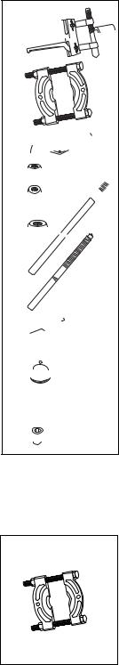
TABLE E - INDIVIDUAL COMPONENTS OF PULLER SETS ATTACHMENTS
Puller Set Attachments |
BHP-1772 |
BHP-262 |
BHP-362 |
BHP-562 |
|
|
|
|
|
|
|
Capacity |
8 ton |
20 ton |
30 ton |
50 ton |
|
|
|
|
|
|
|
5 |
Slotted Crosshead |
HP-1103 |
HP-2103 |
HP-3104 |
HP-5103 |
|
|
|
|
|
|
6 |
Bearing Cup Pull. |
BHP-180 |
BHP-280 |
BHP-380 |
BHP-580 |
|
|
|
|
|
|
7 |
Bearing Puller. |
BHP-181 |
BHP-282 |
BHP-382 |
BHP-582 |
|
|
|
|
|
|
8 |
Leg End Kit |
HP-2009 |
HP-2009 |
HP-3039 |
-- |
(includes 2 leg ends) |
|||||
|
|
|
|
|
|
9 |
Leg Reducer Kit |
HP-2031 |
HP-2031 |
HP-3041 |
-- |
(includes 4 leg ends) |
|||||
|
|
|
|
|
|
10 |
Leg Nut Kit |
HP-2001 |
HP-2001 |
HP-3031 |
HP-5001 |
(includes 2 nuts) |
|||||
|
|
|
|
|
|
11 |
|
HP-1136 (2x) |
HP-2006 (2x) |
HP-3036 (2x) |
HP-5007 (2x) |
Leg 1) |
HP-2007 (2x) |
||||
HP-1137 (2x) |
HP-2008 (2x) |
HP-3037 (2x) |
HP-5008 (2x) |
||
|
|
HP-2012 (2x) |
HP-3038 (2x) |
||
|
|
|
|
||
12 |
Adjusting Rod |
HP-1111 |
HP-2111 |
HP-3111 |
HP-5111 |
|
|
|
|
|
|
16 |
Slide Plate |
HP-1105 (2x) |
HP-2105 (2x) |
HP-3135 (2x) |
HP-5102 (2x) |
|
|
|
|
|
|
17 |
Threaded Saddle |
-- |
HP-2015 |
HP-3015 |
HP-5016 |
|
|
|
|
|
|
18 |
Washer Kit |
HP-1102 |
HP-2002 |
HP-3032 |
-- |
(includes 2 washers) |
|||||
|
|
|
|
|
|
20 |
Mounting Screw Kit |
HP-1213 |
HP-2113 |
HP-3113 |
HP-5113 |
(includes 2 screws) |
|||||
|
|
|
|
|
|
1) See Leg Lengths table on page 11 for additional information.
TABLE F - INDIVIDUAL COMPONENTS OF BEARING PULLER
Bearing Puller |
BHP-181 |
BHP-282 |
BHP-382 |
BHP-582 |
|
|
|
|
|
|
|
Capacity |
8 ton |
20 ton |
30 ton |
50 ton |
|
|
|
|
|
|
|
Rod |
|
|
|
|
|
|
BHP181K |
BHP282K |
BHP582K |
||
Rod Nut |
|||||
|
|
|
|
||
|
|
|
|
|
|
Refer to Illustration 6 or 7 (page 8)
6 


7
5  8
8  9
9 

10 

11 

 12
12 

16
17
18
20
12
 Loading...