

...the world's most energy friendly microcontrollers
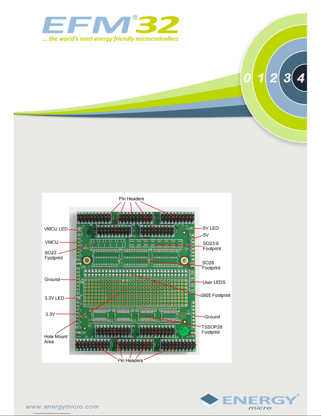
EXP32 Prototype Board
Preliminary
The EXP32 Prototype Board is a versatile plugin module for integration of custom circuits with the EFM32.
The VMCU power domain is tracked by the Advanced Energy Monitor (AEM), which gives detailed information
about the current consumption.
Features:
• Ready-to-use prototyping area for hole-mount, TSSOP, SO, SOT23-6, SOT23 and 0805 SMD components.
• VMCU power domain tracked by the Advanced Energy Monitor (AEM).
• 3.3V and 5V power domains available.
• All EFM32 IO lines directly accessible through pin headers.
• User LEDS ready for use.
• LEDS indicating power.
...the world's most energy friendly microcontrollers
2009-11-19 Rev: t0004_1.00 2
www.energymicro.com
1 Usage
1.1 Placement
This board is intended for use with the EFM32 Gecko Development Kit.
1.2 Prototyping Area
The prototype area supports hole-mounted devices as well as TSSOP, SO, SOT23-x, SOT23 and 0805
SMD components. For some of the IC footprints there is a dedicated footprint for decoupling capacitors.
Please see schematic for details.
1.3 Voltages
The prototype board has 3 supply voltages: 5V, 3.3V and VMCU. VMCU is used by the EFM32 microcontroller, and the corresponding current consumption is tracked by the AEM. For each of the supply
voltages, there is a corresponding LED indicating if the power is present. Either of the voltages may be
used to power custom circuitry, but verify not to connect different power-domains directly.
Note
Make sure not to connect circuitry powered by different supply voltages without proper level
translation! E.g. do not directly connect circuits powered by 3.3V to the EFM32.
1.4 User LEDs
4 user LEDs with corresponding resistors are available on the protoboard. They may easily be soldered
to other circuitry. See schematic for details.
1.5 Pin Headers
The proto board features 10 20-pin headers. Pin 1 and 19 are connected to GND, whereas 2 and 20 may
be connected to VMCU and 3V3 respectively by inserting 0-ohm resistors. See schematic for details.
When the protoboard is connected to the Kit, all GPIO-lines from the MCU-board are available, provided
that the signals are available from the MCU-board. Also, several pheripherals on the Kit mainboard are
available. Please see the schematic of the respective boards for detailed information.
Note
In order for a signal from a EFM32 port to be available on the protoboard, the signal must
be routed out from the EFM32 board.
5
4
3
2
1
D D
C C
B B
A A
EFM32 Development Kit
EFM32 Development KitEFM32 Development Kit
EFM32 Development Kit
Board Function
Board FunctionBoard Function
Board Function Page
PagePage
Page
Front Page 1
2
3
4
5
Revision History
Revision HistoryRevision History
Revision History
Comment
CommentComment
CommentRevision
RevisionRevision
Revision
EXP32 Connector A
EXP32 Connector B
Power Connectors
Dummy Components
Added some and removed some viasPA4
PA5 Removed a rouge via
PA6 BOM changes
A Removed two voltage hooks and
added one gnd hook
Size
Designed:
Revision
Sheet
of
Approved:
Sheet Created Date Sheet Modified Date
Document number
Schematic Title
Design Created Date:
BOM Doc No:
Page Title
A
Thursday, November 19, 2009
1 5
A3
EXP32 Prototyping Board
<Cage Code>
Tuesday, February 17, 2009
Wednesday, December 03, 2008
TOP
/
Front Page

5
4
3
2
1
D D
C C
B B
A A
Port A Port B
Port C Port D
Port E
EXP32_A72
EXP32_A73
EXP32_A74
EXP32_A75
EXP32_A68
EXP32_A70
EXP32_A71
EXP32_A60
EXP32_A61
EXP32_A62
EXP32_A56
EXP32_A57
EXP32_A58
EXP32_A59
EXP32_A64
EXP32_A65
EXP32_A66
EXP32_A67
EXP32_A48
EXP32_A49
EXP32_A50
EXP32_A51
EXP32_A44
EXP32_A45
EXP32_A47
EXP32_A52
EXP32_A53
EXP32_A54
EXP32_A55
EXP32_A40
EXP32_A41
EXP32_A42
EXP32_A43
EXP32_A4
EXP32_A5
EXP32_A6
EXP32_A7
EXP32_A0
EXP32_A8
EXP32_A9
EXP32_A10
EXP32_A11
EXP32_A1
EXP32_A12
EXP32_A13
EXP32_A14
EXP32_A15
EXP32_A2
EXP32_A3
EXP32_A20
EXP32_A21
EXP32_A22
EXP32_A23
EXP32_A16
EXP32_A24
EXP32_A25
EXP32_A26
EXP32_A27
EXP32_A17
EXP32_A28
EXP32_A29
EXP32_A30
EXP32_A31
EXP32_A18
EXP32_A19
EXP32_A32
EXP32_A33
EXP32_A34
EXP32_A35
EXP32_A36
EXP32_A37
EXP32_A38
EXP32_A39
EXP32_A76
EXP32_A77
EXP32_A79
EXP32_A82
EXP32_A83
EXP32_A8
EXP32_A10
EXP32_A12
EXP32_A14
EXP32_A0
EXP32_A2
EXP32_A9
EXP32_A11
EXP32_A13
EXP32_A15
EXP32_A4
EXP32_A6
EXP32_A16
EXP32_A18
EXP32_A20
EXP32_A22
EXP32_A24
EXP32_A26
EXP32_A28
EXP32_A30
EXP32_A17
EXP32_A19
EXP32_A21
EXP32_A23
EXP32_A25
EXP32_A27
EXP32_A29
EXP32_A31
EXP32_A1
EXP32_A3
EXP32_A5
EXP32_A7
EXP32_A56
EXP32_A58
EXP32_A60
EXP32_A62
EXP32_A49
EXP32_A51
EXP32_A53
EXP32_A55
EXP32_A57
EXP32_A59
EXP32_A61
EXP32_A63
EXP32_A33
EXP32_A35
EXP32_A37
EXP32_A39
EXP32_A40
EXP32_A42
EXP32_A44
EXP32_A46
EXP32_A32
EXP32_A34
EXP32_A41
EXP32_A43
EXP32_A45
EXP32_A47
EXP32_A36
EXP32_A38
EXP32_A48
EXP32_A50
EXP32_A52
EXP32_A54
EXP32_A72
EXP32_A74
EXP32_A76
EXP32_A78
EXP32_A65
EXP32_A67
EXP32_A69
EXP32_A71
EXP32_A73
EXP32_A75
EXP32_A77
EXP32_A79
EXP32_A64
EXP32_A66
EXP32_A68
EXP32_A70
EXP32_A78
EXP32_A69
EXP32_A63
EXP32_A46
EXP32_A81
5V
GND
3V3VMCU
GND
3V3VMCU
5V
VMCU3V3
GNDGND
GND
GND
VMCU VMCU3V3 3V3
GND
VMCU3V3
GND
3V3
GND
VMCU
VMCU
GND
3V3
I2C_SDA (p 4)
I2C_SCL (p 4)EEPROM_W P(p 4)
Size
Designed:
Revision
Sheet
of
Approved:
Sheet Created Date Sheet Modified Date
Document number
Schematic Title
Design Created Date:
BOM Doc No:
Page Title
A
Thursday, November 19, 2009
2 5
A3
EXP32 Prototyping Board
<Cage Code>
Monday, March 16, 200 9
Wednesday, December 03, 2008
TOP
/
EXP32 Connector A
C3
10UC310U
P4
HEADER_2X1 0_2.54MM_SMD
P4
HEADER_2X1 0_2.54MM_SMD
1 2
4
8
6
10
3
5
9
7
12
13 14
11
15 16
171918
20
C4
100NC4100N
R5
0R
NM
R5
0R
NM
R8
0R
NM
R8
0R
NM
R1
0R
NM
R1
0R
NM
R4
0R
NM
R4
0R
NM
C7
100NC7100N
C2
100NC2100N
P3
HEADER_2X1 0_2.54MM_SMD
P3
HEADER_2X1 0_2.54MM_SMD
1 2
4
8
6
10
3
5
9
7
12
13 14
11
15 16
171918
20
C9
10UC910U
C1
100NC1100N
C5
100NC5100N
P6
HEADER_2X1 0_2.54MM_SMD
P6
HEADER_2X1 0_2.54MM_SMD
1 2
4
8
6
10
3
5
9
7
12
13 14
11
15 16
171918
20
P2
HEADER_2X1 0_2.54MM_SMD
P2
HEADER_2X1 0_2.54MM_SMD
1 2
4
8
6
10
3
5
9
7
12
13 14
11
15 16
171918
20
P1
BSE_060_01_L_D_A
P1
BSE_060_01_L_D_A
1
3
5
7
9
11
13
15
17
19
21
23
25
27
29
31
33
35
37
39
41
43
45
47
49
51
53
55
57
59
61
63
65
67
69
71
73
75
77
79
81
83
85
87
89
91
93
95
97
99
101
103
105
107
109
111
113
115
117
119
2
4
6
8
10
12
14
16
18
20
22
24
26
28
30
32
34
36
38
40
42
44
46
48
50
52
54
56
58
60
62
64
66
68
70
72
74
76
78
80
82
84
86
88
90
92
94
96
98
100
102
104
106
108
110
112
114
116
118
120
R3
0R
NM
R3
0R
NM
R10
0R
NM
R10
0R
NM
R7
0R
NM
R7
0R
NM
C8
100NC8100N
P5
HEADER_2X1 0_2.54MM_SMD
P5
HEADER_2X1 0_2.54MM_SMD
1 2
4
8
6
10
3
5
9
7
12
13 14
11
15 16
171918
20
R9
0R
NM
R9
0R
NM
R6
0R
NM
R6
0R
NM
C6
10UC610U
R2
0R
NM
R2
0R
NM

5
4
3
2
1
D D
C C
B B
A A
Port H Port I
Port J
Port F Port G
EXP32_B0
EXP32_B1
EXP32_B2
EXP32_B3
EXP32_B8
EXP32_B9
EXP32_B10
EXP32_B11
EXP32_B12
EXP32_B13
EXP32_B14
EXP32_B15
EXP32_B16
EXP32_B17
EXP32_B18
EXP32_B19
EXP32_B4
EXP32_B5
EXP32_B6
EXP32_B7
EXP32_B24
EXP32_B25
EXP32_B26
EXP32_B27
EXP32_B28
EXP32_B29
EXP32_B30
EXP32_B31
EXP32_B32
EXP32_B33
EXP32_B35
EXP32_B20
EXP32_B21
EXP32_B22
EXP32_B23
EXP32_B44
EXP32_B45
EXP32_B46
EXP32_B47
EXP32_B48
EXP32_B49
EXP32_B50
EXP32_B51
EXP32_B52
EXP32_B53
EXP32_B54
EXP32_B55
EXP32_B40
EXP32_B41
EXP32_B42
EXP32_B43
EXP32_B60
EXP32_B61
EXP32_B62
EXP32_B63
EXP32_B64
EXP32_B65
EXP32_B66
EXP32_B67
EXP32_B68
EXP32_B69
EXP32_B70
EXP32_B71
EXP32_B56
EXP32_B57
EXP32_B58
EXP32_B59
EXP32_B36
EXP32_B37
EXP32_B39
EXP32_B38
EXP32_B72
EXP32_B73
EXP32_B75
EXP32_B74
EXP32_B76
EXP32_B77
EXP32_B79
EXP32_B78
EXP32_B34
EXP32_B36
EXP32_B32
EXP32_B34
EXP32_B38
EXP32_B40
EXP32_B42
EXP32_B74
EXP32_B72
EXP32_B41
EXP32_B43
EXP32_B73
EXP32_B75
EXP32_B33
EXP32_B37
EXP32_B39
EXP32_B35
EXP32_B44
EXP32_B48
EXP32_B50
EXP32_B46
EXP32_B56
EXP32_B58
EXP32_B70
EXP32_B76
EXP32_B57
EXP32_B59
EXP32_B71
EXP32_B77
EXP32_B45
EXP32_B47
EXP32_B49
EXP32_B51
EXP32_B52
EXP32_B60
EXP32_B62
EXP32_B64
EXP32_B54
EXP32_B66
EXP32_B68
EXP32_B78
EXP32_B53
EXP32_B55
EXP32_B63
EXP32_B61
EXP32_B65
EXP32_B67
EXP32_B79
EXP32_B69
EXP32_B24
EXP32_B26
EXP32_B28
EXP32_B30
EXP32_B17
EXP32_B19
EXP32_B21
EXP32_B23
EXP32_B25
EXP32_B27
EXP32_B29
EXP32_B31
EXP32_B1
EXP32_B3
EXP32_B5
EXP32_B7
EXP32_B8
EXP32_B10
EXP32_B12
EXP32_B14
EXP32_B0
EXP32_B2
EXP32_B9
EXP32_B11
EXP32_B13
EXP32_B15
EXP32_B4
EXP32_B6
EXP32_B16
EXP32_B18
EXP32_B20
EXP32_B22
5V
GND
3V3VMCU
GND GND
3V3VMCU
5V
VMCU3V3
GNDGND
3V3
GND
VMCU 3V3
GND
VMCU
3V3
GND
VMCU
VMCU3V3
GND
3V3
GND
VMCU
Size
Designed:
Revision
Sheet
of
Approved:
Sheet Created Date Sheet Modified Date
Document number
Schematic Title
Design Created Date:
BOM Doc No:
Page Title
A
Thursday, November 19, 2009
3 5
A3
EXP32 Prototyping Board
<Cage Code>
Monday, March 16, 200 9
Wednesday, December 03, 2008
TOP
/
EXP32 Connector B
P9
HEADER_2X1 0_2.54MM_SMD
P9
HEADER_2X1 0_2.54MM_SMD
1 2
4
8
6
10
3
5
9
7
12
13 14
11
15 16
171918
20
R17
0R
NM
R17
0R
NM
R18
0R
NM
R18
0R
NM
C13
100N
C13
100N
R14
0R
NM
R14
0R
NM
R15
0R
NM
R15
0R
NM
R16
0R
NM
R16
0R
NM
R13
0R
NM
R13
0R
NM
P12
HEADER_2X1 0_2.54MM_SMD
P12
HEADER_2X1 0_2.54MM_SMD
1 2
4
8
6
10
3
5
9
7
12
13 14
11
15 16
171918
20
P7
BSE_060_01_L_D_A
P7
BSE_060_01_L_D_A
1
3
5
7
9
11
13
15
17
19
21
23
25
27
29
31
33
35
37
39
41
43
45
47
49
51
53
55
57
59
61
63
65
67
69
71
73
75
77
79
81
83
85
87
89
91
93
95
97
99
101
103
105
107
109
111
113
115
117
119
2
4
6
8
10
12
14
16
18
20
22
24
26
28
30
32
34
36
38
40
42
44
46
48
50
52
54
56
58
60
62
64
66
68
70
72
74
76
78
80
82
84
86
88
90
92
94
96
98
100
102
104
106
108
110
112
114
116
118
120
P11
HEADER_2X1 0_2.54MM_SMD
P11
HEADER_2X1 0_2.54MM_SMD
1 2
4
8
6
10
3
5
9
7
12
13 14
11
15 16
171918
20
C18
10U
C18
10U
P10
HEADER_2X1 0_2.54MM_SMD
P10
HEADER_2X1 0_2.54MM_SMD
1 2
4
8
6
10
3
5
9
7
12
13 14
11
15 16
171918
20
C16
100N
C16
100N
C17
100N
C17
100N
C10
100N
C10
100N
C15
10U
C15
10U
C14
100N
C14
100N
R19
0R
NM
R19
0R
NM
R11
0R
NM
R11
0R
NM
R20
0R
NM
R20
0R
NM
C11
100N
C11
100N
R12
0R
NM
R12
0R
NM
C12
10U
C12
10U
P8
HEADER_2X1 0_2.54MM_SMD
P8
HEADER_2X1 0_2.54MM_SMD
1 2
4
8
6
10
3
5
9
7
12
13 14
11
15 16
171918
20

5
4
3
2
1
D D
C C
B B
A A
MCU Voltage Header
3V3 Header
GND Header GND Header
5V Header
GNDGND
VMCU
GND
3V3
GND
GND
5V
GND
5V
GND
GND
GND
3V3
3V3
GND
3V3
GND
I2C_SDA(p 2)
I2C_SCL(p 2)
EEPROM_W P (p 2)
Size
Designed:
Revision
Sheet
of
Approved:
Sheet Created Date Sheet Modified Date
Document number
Schematic Title
Design Created Date:
BOM Doc No:
Page Title
A
Thursday, November 19, 2009
4 5
A3
EXP32 Prototyping Board
<Cage Code>
Monday, March 16, 200 9
Wednesday, December 03, 2008
TOP
/
Power Connectors
R260RR26
0R
C30
100N
C30
100N
R210RR21
0R
C23
100N
C23
100N
C27
100N
C27
100N
U1A
24AA024
U1A
24AA024
SDA
5
SCL
6
WP
7
A0
1
A1
2
A2
3
J1
1X8 2.54MMJ11X8 2.54MM
1
2
3
4
5
6
7
8
R25
10K
R25
10K
C26
100N
C26
100N
C24
100N
C24
100N
LED1
GREEN
LED1
GREEN
21
J3
1X8 2.54MMJ31X8 2.54MM
1
2
3
4
5
6
7
8
J2
1X8 2.54MMJ21X8 2.54MM
1
2
3
4
5
6
7
8
C32
100N
C32
100N
C31
100N
C31
100N
TP2
KOA_1206
TP2
KOA_1206
J4
1X8 2.54MMJ41X8 2.54MM
1
2
3
4
5
6
7
8
R23
470R
R23
470R
C25
100N
C25
100N
J5
1X8 2.54MMJ51X8 2.54MM
1
2
3
4
5
6
7
8
U1B
24AA024
U1B
24AA024
VCC
8
VSS
4
R240RR24
0R
C34
10N
C34
10N
Q1
BSS138WQ1BSS138W
1
32
R28
10K
R28
10K
C28
100N
C28
100N
LED3
GREEN
LED3
GREEN
21
C22
100N
C22
100N
C19
100N
C19
100N
TP3
KOA_1206
TP3
KOA_1206
C21
100N
C21
100N
C33
100N
C33
100N
TP1
KOA_1206
TP1
KOA_1206
R271KR27
1K
C29
100N
C29
100N
C20
100N
C20
100N
TP5
KOA_1206
TP5
KOA_1206
R221KR22
1K
LED2
GREEN
LED2
GREEN
21

5
4
3
2
1
D D
C C
B B
A A
GND
VMCU3V3
GND
Size
Designed:
Revision
Sheet
of
Approved:
Sheet Created Date Sheet Modified Date
Document number
Schematic Title
Design Created Date:
BOM Doc No:
Page Title
A
Thursday, November 19, 2009
5 5
A3
EXP32 Prototyping Board
<Cage Code>
Monday, March 16, 200 9
Wednesday, December 03, 2008
TOP
<Schematic Path>
Dummy Components
LED5
GREEN
LED5
GREEN
21
C42
100N
C42
100N
Q6Q6
1
2 3
U28
SOT23-6 Dumm y
U28
SOT23-6 Dumm y
1
1
2
2
334
4
5
5
6
6
R29
470R
R29
470R
C47
100N
C47
100N
U8
SO28 Dummy
U8
SO28 Dummy
1
1
2
2
3
3
4
4
5
5
6
6
7
7
8
8
9
9
10
10
11
11
12
12
13
13
141415
15
16
16
17
17
18
18
19
19
20
20
21
21
22
22
23
23
24
24
25
25
26
26
27
27
28
28
Q2Q2
1
2 3
U22
HEADER_30X1
U22
HEADER_30X1
1
1
2
2
3
3
4
4
5
5
6
6
7
7
8
8
9
9
10
10
11
11
12
12
13
13
14
14
15
15
16
16
17
17
18
18
19
19
20
20
21
21
22
22
23
23
24
24
25
25
26
26
27
27
28
28
29
29
30
30
C37
100N
C37
100N
C38
100N
C38
100N
R32
470R
R32
470R
U20
HEADER_30X1
U20
HEADER_30X1
1
1
2
2
3
3
4
4
5
5
6
6
7
7
8
8
9
9
10
10
11
11
12
12
13
13
14
14
15
15
16
16
17
17
18
18
19
19
20
20
21
21
22
22
23
23
24
24
25
25
26
26
27
27
28
28
29
29
30
30
U2
TSSOP28U2TSSOP28
1
1
2
2
3
3
4
4
5
5
6
6
7
7
8
8
9
9
10
10
11
11
12
12
13
13
14
14
28
28
27
27
26
26
25
25
24
24
23
23
22
22
21
21
20
20
19
19
18
18
17
17
16
16
15
15
U21
HEADER_30X1
U21
HEADER_30X1
1
1
2
2
3
3
4
4
5
5
6
6
7
7
8
8
9
9
10
10
11
11
12
12
13
13
14
14
15
15
16
16
17
17
18
18
19
19
20
20
21
21
22
22
23
23
24
24
25
25
26
26
27
27
28
28
29
29
30
30
C35
100N
C35
100N
U14
SOT23-6 Dumm y
U14
SOT23-6 Dumm y
1
1
2
2
334
4
5
5
6
6
Q5Q5
1
2 3
U12
SO28 Dummy
U12
SO28 Dummy
1
1
2
2
3
3
4
4
5
5
6
6
7
7
8
8
9
9
10
10
11
11
12
12
13
13
141415
15
16
16
17
17
18
18
19
19
20
20
21
21
22
22
23
23
24
24
25
25
26
26
27
27
28
28
U3
SO28 Dummy
U3
SO28 Dummy
1
1
2
2
3
3
4
4
5
5
6
6
7
7
8
8
9
9
10
10
11
11
12
12
13
13
141415
15
16
16
17
17
18
18
19
19
20
20
21
21
22
22
23
23
24
24
25
25
26
26
27
27
28
28
C49
100N
C49
100N
Q3Q3
1
2 3
C39
100N
C39
100N
C46
100N
C46
100N
U7
TSSOP28U7TSSOP28
1
1
2
2
3
3
4
4
5
5
6
6
7
7
8
8
9
9
10
10
11
11
12
12
13
13
14
14
28
28
27
27
26
26
25
25
24
24
23
23
22
22
21
21
20
20
19
19
18
18
17
17
16
16
15
15
U9
SOT23-6 Dumm y
U9
SOT23-6 Dumm y
1
1
2
2
334
4
5
5
6
6
U10
SOT23-6 Dumm y
U10
SOT23-6 Dumm y
1
1
2
2
334
4
5
5
6
6
U23
HEADER_30X1
U23
HEADER_30X1
1
1
2
2
3
3
4
4
5
5
6
6
7
7
8
8
9
9
10
10
11
11
12
12
13
13
14
14
15
15
16
16
17
17
18
18
19
19
20
20
21
21
22
22
23
23
24
24
25
25
26
26
27
27
28
28
29
29
30
30
U6
SOT23-6 Dumm y
U6
SOT23-6 Dumm y
1
1
2
2
334
4
5
5
6
6
C41
100N
C41
100N
U19
HEADER_30X1
U19
HEADER_30X1
1
1
2
2
3
3
4
4
5
5
6
6
7
7
8
8
9
9
10
10
11
11
12
12
13
13
14
14
15
15
16
16
17
17
18
18
19
19
20
20
21
21
22
22
23
23
24
24
25
25
26
26
27
27
28
28
29
29
30
30
Q4Q4
1
2 3
C40
100N
C40
100N
U26
TSSOP28
U26
TSSOP28
1
1
2
2
3
3
4
4
5
5
6
6
7
7
8
8
9
9
10
10
11
11
12
12
13
13
14
14
28
28
27
27
26
26
25
25
24
24
23
23
22
22
21
21
20
20
19
19
18
18
17
17
16
16
15
15
U18
SOT23-6 Dumm y
U18
SOT23-6 Dumm y
1
1
2
2
334
4
5
5
6
6
U5
RESU5RES
1
1
2
2
3
3
4
4
5
5
6
6
7
7
8
8
9
9
10
10
11
11
12
12
13
13
14
14
15
15
16
16
17
17
18
18
19
19
20
20
21
21
22
22
23
23
24
24
25
25
26
26
27
27
28
28
29
29
303031
31
32
32
33
33
34
34
35
35
36
36
37
37
38
38
39
39
40
40
41
41
42
42
43
43
44
44
45
45
46
46
47
47
48
48
49
49
50
50
51
51
52
52
53
53
54
54
55
55
56
56
57
57
58
58
59
59
60
60
C36
100N
C36
100N
U11
TSSOP28
U11
TSSOP28
1
1
2
2
3
3
4
4
5
5
6
6
7
7
8
8
9
9
10
10
11
11
12
12
13
13
14
14
28
28
27
27
26
26
25
25
24
24
23
23
22
22
21
21
20
20
19
19
18
18
17
17
16
16
15
15
R31
470R
R31
470R
LED6
GREEN
LED6
GREEN
21
U13
SOT23-6 Dumm y
U13
SOT23-6 Dumm y
1
1
2
2
334
4
5
5
6
6
U17
HEADER_30X1
U17
HEADER_30X1
1
1
2
2
3
3
4
4
5
5
6
6
7
7
8
8
9
9
10
10
11
11
12
12
13
13
14
14
15
15
16
16
17
17
18
18
19
19
20
20
21
21
22
22
23
23
24
24
25
25
26
26
27
27
28
28
29
29
30
30
Q7Q7
1
2 3
U16
HEADER_30X1
U16
HEADER_30X1
1
1
2
2
3
3
4
4
5
5
6
6
7
7
8
8
9
9
10
10
11
11
12
12
13
13
14
14
15
15
16
16
17
17
18
18
19
19
20
20
21
21
22
22
23
23
24
24
25
25
26
26
27
27
28
28
29
29
30
30
LED4
GREEN
LED4
GREEN
21
C45
100N
C45
100N
LED7
GREEN
LED7
GREEN
21
U15
HEADER_30X1
U15
HEADER_30X1
1
1
2
2
3
3
4
4
5
5
6
6
7
7
8
8
9
9
10
10
11
11
12
12
13
13
14
14
15
15
16
16
17
17
18
18
19
19
20
20
21
21
22
22
23
23
24
24
25
25
26
26
27
27
28
28
29
29
30
30
C50
100N
C50
100N
U4
SOT23-6 Dumm y
U4
SOT23-6 Dumm y
1
1
2
2
334
4
5
5
6
6
C48
100N
C48
100N
R30
470R
R30
470R

C19C20C21C22C23 C24C25C26C27C28
C29C30C31C32C33
C35
C36
C37
C38
C39
C40
C41
C42
C45
C46
C47
C48
C49
C50
J1
J2
J3
J4
J5
LED1
LED2
LED3
LED4
LED5
LED6
LED7
P2 P3 P4
P5 P6
P8 P9 P10
P11 P12
Q2 Q3 Q4 Q5 Q6 Q7
R1
R2
R3
R4
R5
R6
R7
R8
R9
R10
R11
R12
R13
R14
R15
R16
R17
R18
R19
R20
R21 R24
R26
TP1
TP2 TP3
TP5
U2
U3
U4
U6
U7
U8
U9
U10
U11
U12
U13
U14
U18
U26
U28

C1
C2
C3
C4
C5
C6
C7
C8
C9
C10
C11
C12
C13
C14
C15
C16
C17
C18
C34
P1
P7
Q1
R22
R23
R25
R27
R28
R29
R30
R31
R32
U1

 Loading...