


Installer: Leave this manual with the appliance. Consumer: Retain this manual for future reference.
OPERATING INSTRUCTIONS AND OWNER’S MANUAL
Model #
HS25NG
HS22LP
READ INSTRUCTIONS CAREFULLY: Read and follow all instructions. Place instructions in a safe place for future reference. Do not allow anyone who has not read these instructions to assemble, light, adjust or operate the heater.
GAS FIRED INFRA-RED WORKSHOP HEATER
LANGUAGES
 ENGLISH
Pages E1 — E16
SPANISH
Pages S1 — S16
FRENCH
Pages F1 — F16
 WARNING: If the information in this manual is not followed exactly, a fire or explosion may result causing property damage, personal injury, or loss of life.
-Do not store or use gasoline or other flammable vapors and liquids in the vicinity of this or any other appliance.
-WHAT TO DO IF YOU SMELL GAS
•Shut off gas supply
•Do not try to light any appliance
•Do not touch an electrical switch; do not use any phone in your building.
•Immediately call your gas supplier from a neighbor’s phone. Follow the gas supplier’s instructions.
•If you cannot reach your gas supplier, call the fire department.
-Installation and service must be performed by a qualified installer, service agency, or the gas supplie
 WARNING: This is an unvented gas-fired heater. It uses air (oxygen) from the room in which it is installed. Provisions for adequate combustion and ventilation air must be provided. Refer to Fresh Air for Combustion and Ventilation section on page 6 of this manual.
 WARNING: Improper installation, adjustment, alteration, service or maintenance can cause property damage, injury or death. Read the installation, operation, and maintenance instructions thoroughly before installing or servicing this equipment. For assistance or additional information consult a qualified installer, service agency, or gas supplier.
HEATSTAR, INC., 4560 W. 160TH ST., CLEVELAND, OHIO 44135 · |
2016 |
18672 |
WARNINGS
 WARNING: Improper installation, adjustment, alteration, service or maintenance can cause property damage, injury or death. Read the installation, operation, and maintenance instructions thoroughly before installing or servicing this equipment. For assistance or additional information consult a qualified installer, service agency, or gas supplier.
 WARNING: When used without fresh air, heater may give off CARBON MONOXIDE, an odorless poisonous gas. OPEN WINDOW AN INCH OR TWO FOR FRESH AIR WHEN USING HEATER.
 WARNING: This heater is equipped with a PILOT LIGHT SAFETY SYSTEM. DO NOT TAMPER WITH PILOT LIGHT SAFETY SYSTEM.
 WARNING: If heater shuts off, do not relight until you provide fresh air. If heater keeps shutting off, have it serviced. Keep burner and control clean. Open door for 5 minutes.
Maintain clearances as shown in Figure 2 or on heater nameplate.
•DO NOT USE MATCH OR OTHER FLAME
FOR LEAK TESTING.
•DO NOT EXCEED 1/2 PSI INLET PRESSURE TO HEATER.
DANGER: Carbon monoxide poisoning may lead to death.
Carbon Monoxide Poisoning:
Early signs of carbon monoxide poisoning resemble the flu, with headaches, dizziness, or nausea. If you have these signs, the heater may not be working properly. Get fresh air at once! Have heater serviced. Some people are more affected by carbon monoxide than others. These include pregnant women, persons with heart or lung disease or anemia, those under the influence of alcohol, and those at high altitudes.
CAUTION
•Never connect gas valve or thermostat to line voltage or a transformer.
•If the infra-red color of the grid becomes dull when the building furnace is operating, consult gas supplier on correct gas supply piping sizes.
•This heater is for indoor installation only!
NOTE
Gasket binder material used in this heater assembly will temporarily emit an odor and/or vapor. This condition will clear up in approximately 20 minutes and thereafter will not reoccur. Refer to Chapter 2 for ventilation.
WARNING:
The State of California requires the following warning:
COMBUSTION BY-PRODUCTS PRODUCED
WHEN USING THIS PRODUCT CONTAIN
CARBON MONOXIDE, A CHEMICAL KNOWN
TO THE STATE OF CALIFORNIA TO CAUSE
CANCER AND BIRTH DEFECTS (OR OTHER REPRODUCTIVE HARM).
TABLE OF CONTENTS
Chapter |
Title |
Page |
|
I |
Introduction. |
............................................ |
E3 |
II |
Heater Installation................................... |
E5 |
|
III |
Heater Operating .................Instructions |
E10 |
|
IV |
Operator Maintenance .........Instructions |
E12 |
|
V |
Replacement ...........................Parts List |
E15 |
|
Model # HS25NG/LP |
E2 |
Installation instructions and Owner’s Manual |
CHAPTER I
INTRODUCTION
1. EQUIPMENT
This heater is the consumer version of our highly successful, thoroughly tested, gas fired, infrared, industrial utility heater.
This heater does not require an external electrical source for operation.
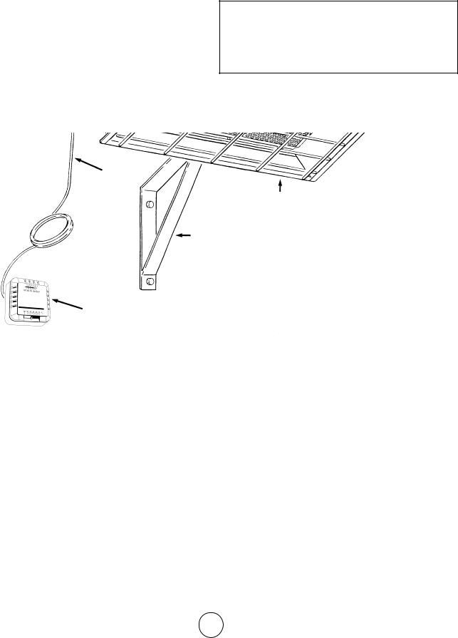
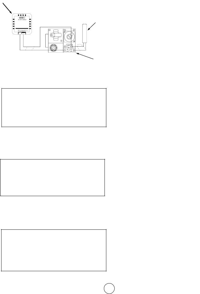
The major components of the heater and a typical installation are identified in Figure 1. The basic
heater consists of the complete burner assembly, flue deflector, grid, reflector assembly and face guard.
2. PURPOSE OF EQUIPMENT
WARNINGS
 This heater is for indoor installation only.
 This heater is designed to heat indoor areas. Do not use for inhabited or small, enclosed areas.
GAS CONTROL
VALVE
POWERPILE
GENERATOR
EXHAUST
VENT
THERMOSTAT
CABLE
BASIC HEATER
WALL MOUNTING
BRACKET
THERMOSTAT
Figure 1. Heater Major Components
Model # HS25NG/LP |
E3 |
Installation instructions and Owner’s Manual |

3.GENERAL INFORMATION
•Your heater comes fully assembled and is tested at the factory with the appropriate type of gas and at the input pressures stated on the nameplate.
•Upon receipt and prior to attempting installation, be sure to inspect the heater and its packaging for damage and/or missing components. If damage is found or missing components are suspected, contact your dealer. See Chapter 5 for a complete listing of items required for the safe and efficient installation and use of this heater.
•Never attempt to operate the heater using a fuel other than that specifically identified on the nameplate.
•The installation of the heater must conform with all local building codes or, in absence of governing local codes, with the National Fuel Gas
Code, ANSI Z223.1 (NFPA 54). This code can be obtained from either the: Canadian Standards Association, 8501 East Pleasant Valley Road, Cleveland, OH 44131; or, NFPA, Battery March Park, Quincy, MA 02269.
•Canadian installations must comply with CAN/ CGA-B149.1.2 gas code which can be purchased from Canadian Gas Association, 55 Scarsdale Road, Don Mills, Ontario M3B 2R3.
•Contact factory when appliance is to be installed at high altitudes. Factory can supply high altitude conversion kit with instructions and data plate.
•A plugged 1/8” N.P.T. Test Gage Connection is provided on the heater gas control.
•See Tables 1 and 2 for heater specifications:
 WARNING: Improper installation, adjustment, alteration, service or maintenance can cause property damage, injury or death. Read the installation, operation, and maintenance instructions thoroughly before installing or servicing this equipment. For assistance or additional information consult a qualified installer, service agency, or gas supplier.
•For additional information contact Mr. Heater Toll-
Free 866-477-2194—www.mrheater.com
The following extra NFPA Manuals are helpful when installing this heater in a location not anticipated in this manual:
Number Related Subject
NFPA 88 Clearances to Combustible Surfaces NFPA 409 Clearances to Combustible Surfaces
 DO NOT EXCEED 1/2 PSI INLET PRESSURE TO HEATER
Provide adequate clearance to combustibles per Table 3 at control end of heater for servicing and minimum on top and sides for ventilation and combustion air supply.
A minimum clearance of 8’ above floor for public garages in accordance with NFPA No. 88 most recent edition, or Figure 1; whichever is larger.
Canadian installations in public garages must comply with CGA 149B.1.9 most recent edition.
 WARNING: Maintain clearances as shown in Figure 2 or on heater nameplate.
Table 1. BTU Ratings and Supply Pressures
MODEL |
BTU/HR. RATING |
|
|
GAS SUPPLY PRESSURE (W.C.) |
|
ORIFICE |
|||||
NO. |
|
GAS |
|
MIN. |
MAX. |
MANIFOLD |
SIZE |
|
|||
|
NATURAL |
PROPANE |
NAT. |
|
L.P. |
NAT. |
L.P. |
NAT. |
L.P. |
NAT. |
L.P. |
MH/HS25NG |
25,000 |
— |
7.0” |
|
— |
14” |
— |
6” |
— |
45 |
— |
MH/HS22LP |
— |
22,000 |
— |
|
11” |
— |
14” |
— |
10” |
— |
55 |
|
|
|
|
|
|
|
|
|
|
|
|
Table 2. Heater Dimensions and Orifice Sizes
MODEL |
OPERATING |
ORIFICE SIZE |
INPUT |
|
|
SIZE |
|
|
||
NO. |
PRESSURE |
BURNER |
PILOT |
BTU/H |
WIDTH |
LENGTH |
|
HEIGHT |
WEIGHT |
|
MH/HS25NG |
6.0”w.c. |
45 |
.018 |
25.000 |
12-1/4” |
29-3/4” |
|
7” |
20 lb. |
|
MH/HS22LP |
10”w.c. |
55 |
.011 |
22,000 |
12-1/4” |
29-3/4” |
|
7” |
20 lb. |
|
|
|
|
|
|
|
|
|
|
|
|
Model # HS25NG/LP |
E4 |
Installation instructions and Owner’s Manual |
CHAPTER II
HEATER INSTALLATION
1.GENERAL INSTALLATION INFORMATION AND REQUIREMENTS
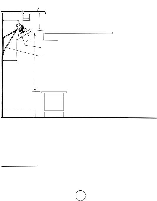
•The required minimum clearances to combustible surfaces are illustrated in Figure 2 and Table 3.
As shown on Figure 2, the front of the heater is installed at the minimum required clearance to
combustible surfaces and toward open space, and then the other sides must have a minimum clearance of 16 inches to combustible surfaces.
EXHAUST CEILING
VENT
16” |
14” |
MINIMUM |
MINIMUM |
OPEN
WORKSHOP DOOR
30 |
16” |
|
MINIMUM |
|
HEATER |
|
WALL BRACK- |
14-1/2” |
ET |
|
48” |
|
MINIMUM |
NOTE:
1.ONLY FLUE SIDE OF HEATER CAN BE ELEVATED (30o).
2.HEATER SIDE REFLECTOR MUST BE HORIZONTAL.
FLOOR LINE
Figure 2. Installation Clearances to Combustible Surfaces
Table 3. Installation, Ventilation and Mounting Information
|
BTU/HR. RATING |
NORMAL |
|
|
|
|
||
MODEL |
GAS |
|
MOUNTING |
CLEARANCES TO COMBUSTIBLE SURFACES |
||||
NO. |
NAT. |
L.P. |
POSITION |
TOP |
SIDES |
BACK |
BELOW |
|
MH/HS25NG |
25,000 |
— |
30o |
14” |
16” |
16” |
48” |
|
MH/HS22LP |
— |
22,000 |
|
30o |
14” |
16” |
16” |
48” |
|
|
|
|
|
|
|
|
|
Model # HS25NG/LP |
E5 |
Installation instructions and Owner’s Manual |

•This heater may be mounted on any wall; however, it is recommended that the heater be mounted in the middle of the wall opposite any overhead doors.
•When selecting installation locations for this heater ensure that the opening of any exterior or interior doors or windows will not violate minimum clearances or contact any heater components.
•If an overhead door is installed in the building, verify that the heater is not installed in such a way as to interfere with door operation and verify that the door in its open position will not reduce clearances below the minimum requirements. Never mount the heater in such a way that would position the heater above an opened overhead door.
•In most cases the infiltration around your uninsulated entry doors and windows will provide enough air flow for efficient heater operation.
HEATER VENTILATION
Unrestricted air flow during heater operation is essential to prevent the area above the installed heater from overheating. If your workshop/utility building is tightly insulated (including windows, doors, openings, etc.) the following ventilating methods must be followed:
•A single exhaust vent is supplied with your heater for your convenience. This vent must be located above the heater (preferably at the highest point in the building interior) and it must vent to the exterior of the building. An additional vent is available from the factory for those having a finished workshop or utility building.
•An intake vent, or equivalent, from the exterior of the building and having an effective area of 75 square inches must be located below the heater (preferably within 2 feet of the building’s floor).
•Openings equivalent to intake vent would be: partially open doors and partially open windows.
•Openings of this size (5 inch by 13 inch, or 3 inch by 25 inch) will prevent dangerous heat buildup above the heater.
Ensure that no gas lines or electrical wiring or conduits will interfere with mounting of the heater to the wall.
Depending on local codes and requirements and the installer’s skill level, the sizing and installation of gas lines required to supply the heater may require the assistance of a professional. If in doubt as to these
requirements, discuss the requirements of this manual with the dealer from whom the heater was purchased and your gas supplier, or call our customer service department at 1-866-477-2194.
The selection of the thermostat mounting location is critical to efficient and effective heater operation.
•The thermostat should be mounted about 5 feet above the floor where air can circulate freely around it.
•The thermostat should not be mounted directly to a cold exterior wall without an insulated mounting block.
•The thermostat should not be mounted in direct drafts.
•The thermostat should not be mounted directly below the installed the heater.
•The thermostat should not be installed at a distance that is farther from the heater than the length of the thermostat cable.
2.HEATER MOUNTING INSTRUCTIONS
After selecting the heater installation location and the thermostat location and after verifying and ensuring that all of the above placement requirements are fulfilled, mount the heater as follows:
A.Determine how you wish to install the vent based on the construction of the building and your personal preference. (i.e., do you wish the flanged (finished) side on the interior or the exterior of the building or do you want two vents so that both exterior and interior will be finished?) If needed, order an additional vent from the factory. Our address and toll free phone number are on the rear cover of this manual. Install the vent as follows:
1.See Figure 3 for dimensions and information on the vent.
2.Select a place as high above the heater as possible in accordance with the above requirements and ensure that the vent or vents will not contact or interfere with existing building systems (i.e., ducts, wiring, plumbing, etc.)
3.Place the unfinished side of the vent against the wall in its elected location and trace its dimensions on the wall with a pencil or other suitable marker.
4.Cut or otherwise open a hole in the wall, or walls for finished buildings, having the dimensions of the unfinished side of the vent.
5.Install the vent or vents as desired and retain
Model # HS25NG/LP |
E6 |
Installation instructions and Owner’s Manual |
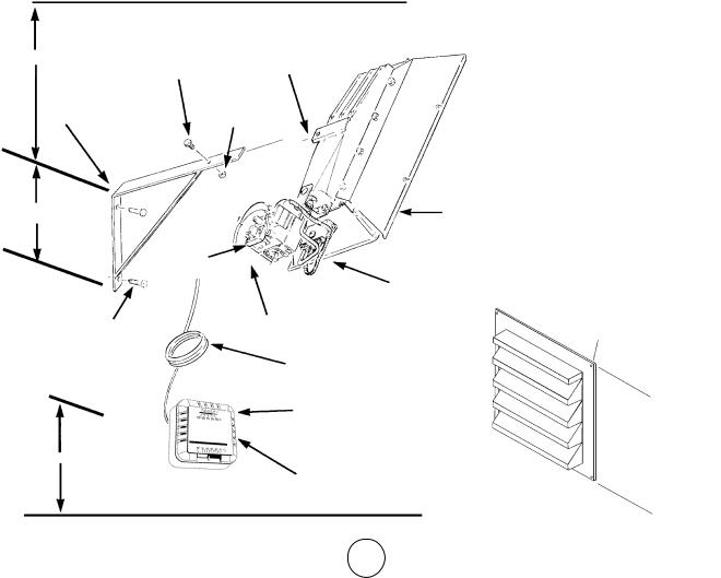
with 4 suitable fasteners through the predrilled holes in vent flange.
B.Prepare to install the heater wall mounting bracket as follows:
1.If the wall mounting bracket is to be attached to a stud and wallboard wall, refer to Figure 3 for dimensions, locate a stud, and drill two 1/8” pilot holes into the stud centerline. Use template for simplified installation.
2.If the wall mounting bracket is to be attached to a brick or masonry wall, refer to Figure 3 for dimensions. Obtain two 1/4 inch (inside diameter) expansion anchors and determine the correct drill size to be used with them. Drill the appropriate size holes in the brick or masonry to accept the anchors.
C.Place the wall mounting bracket on the wall and align the two through holes on the bracket with the pilot holes or anchors. Install 1/4 inch by 2-1/2 inch lag screws through the bracket into the stud or anchors. Tighten securely.
D.Locate heater mounting clip on back of heater and select the 1/4” – 20 by 3/4” hex head bolt and 1/4” -
20hex nut.
E.Position the heater as shown in Figure 3 and slide the heater mounting clip over the bracket and install the bolt through the clip and bracket.
F.Thread the hex nut onto the bolt and tighten securely.
G.Ensure that the selected thermostat location meets all of the above requirements. Refer to the instructions that come with the thermostat for additional grounding information and mounting instruction.
H.If the wall is of stud and wallboard construction, then use the #6 by 1 inch sheet metal screws, included with the thermostat, and mount the thermostat in the selected location.
I.If wall is brick or masonry, the appropriate anchors must be obtained to accommodate thermostat mounting screws. Use the back plate of the thermostat as a template to mark the hole locations, drill appropriate size anchor holes, install the anchors, securely attach the thermostat using the mounting screws.
J.Connect thermostat wires to gas valve as shown in Figure 4.
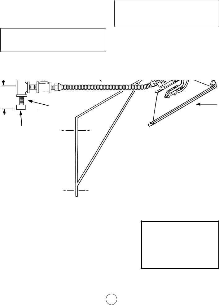
Figure 3. Heater Mounting Information
|
CEILING |
|
|
|
HEATER |
|
|
24” MIN |
1/4”-20x3/4” HEX- |
MOUNTING |
|
CLIP |
|||
|
HEAD BOLT |
||
|
|
||
HEATER WALL |
|
||
MOUNTING |
1/4”-20 |
|
|
BRACKET |
HEX NUT |
||
9” FLUE DEFLECTOR
GAS
CONTROL
VALVE
HEATER REFLECTOR
1/4” X 2-1/2” LONG LAG SCREWS (2 REQUIRED)
58”
1/2” NPT GAS INLET
(DO NOT EXCEED 1/2 PSI)
THERMOSTAT CABLE (SEE FIGURE 4)
#6 X 1” SHEET METAL SCREWS
(2 REQUIRED - INCLUDED WITH THERMOSTAT)
UNFINISHED
SIDE
THERMOSTAT (SEE INSTRUCTIONS INCLUDED WITH THERMOSTAT
FLOOR
FINISHED
SIDE
FLANGE
PREDRILLED
HOLES
Model # HS25NG/LP |
E7 |
Installation instructions and Owner’s Manual |
THERMOSTAT
POWERPILE GAS VALVE
POWERPILE GENERATOR
Figure 4. Connection Diagram
Refer to National Electrical Code NFPA70-1993 and for Canadian installations to current CODE C22.1-
3. CONNECTING HEATER TO GAS SUPPLY
 WARNING: Depending on local codes and requirements and the installer’s skill level, the sizing and installation of gas lines required to safely and efficiently supply the heater may require the assistance of a professional. If in doubt as to these requirements, discuss the requirements of this manual with the dealer from whom the heater was purchased and your gas supplier.
3.1Gas Supply Requirements
•See Tables 1 and 2 for gas supply minimum, maximum, operating, and manifold pressures for both heater models. Pressures are provided in inches of W.C. (water column). Also, see heater rating plates located on the heater.
 WARNING: Model MH/HS25NG is designed to burn natural gas and it comes equipped with a regulator. The regulator is built into the gas valve. The maximum inlet pressure to this regulator is 1/2 psi (14 in. W.C.) If gas line pressure exceeds 1/2 psi, then an additional regulator must be installed before the heater/regulator to step down the pressure to a maximum of 1/2 psi.
•Most residential natural gas services provide a line pressure of 4 oz. (6.9 in. W.C.). If in doubt consult your natural gas supplier.
•To ensure the best performance from your natural gas heater make sure the supply manifold pressure is at least 6” W.C.
 WARNING: Model MH/HS22LP is designed to burn liquefied petroleum (LP) gas and it comes equipped with a regulator. The regulator is built into the gas valve. The maximum inlet pressure to this regulator is 1/2 psi (14 in. W.C.). If gas line pressure exceeds 1/2 psi, then an additional regulator must be installed before the heater/ regulator to step down the pressure to a maximum of 1/2 psi.
•To ensure the best performance from your LP gas
heater, make sure the supply manifold pressure is at least 1/2 psi (14 in W.P.).
3.2 Piping Requirements
All piping installed must comply with local codes and ordinances or with National Fuel Gas Code,
ANSI Z223.1 (NFPA 54), whichever takes precedence. When installing piping, the following requirements must be taken into consideration: Canadian installations must comply with the B149.1.2 Gas Code.
•Use new properly reamed black pipe free from chips.
•Apply a good quality pipe compound to all male threads as shown in Figure 5 prior to assembly. If LP gas is the fuel, ensure that pipe compound is resistant to LP gas. Do not use Teflon™ tape.
USE MODERATE AMOUNT OF PIPE DOPE
LEAVE 2 THREADS BARE
Figure 5. Pipe Compound Application
•Male threads on pipe to be installed into gas valve shall meet the requirements of Figure 6. Threads longer than those shown in the figure may cause gas valve distortion and malfunction.
•A sediment trap meeting the typical requirements of Figure 7 shall be installed in the line to the gas valve.
•A dedicated shutoff valve for the heater must be installed in the gas supply line.
3.3Piping Installation
While ensuring that all of the above gas supply re-
3/4” MAXIMUM THREAD LENGTH
1/2” BLACK PIPE
GAS VALVE BODY
1/2” MAXIMUM
DEPTH OF INSERTS INTO GAS VALVE
Figure 6. Gas Valve Connection Requirements
Model # HS25NG/LP |
E8 |
Installation instructions and Owner’s Manual |
quirements and piping requirements are fulfilled, install piping as follows:
A.In accordance with the above piping requirements, assemble piping, sediment trap, shutoff valve, and necessary fittings. Tighten all components securely.
 WARNING: Failure to ensure that male threads on pipe to be installed into gas valve meet the requirements of Figure 6 may cause gas valve damage, distortion and malfunction.
B.Install a threaded nipple, prepared in accordance with paragraph 3.2 into gas valve.
C.Connect gas piping to nipple installed in the gas valve.
 WARNING: When testing gas piping use only a soap and water solution. Do not use a match or other flame for leak testing. If during leakage check gas is smelled, turn off the gas supply and ventilate building.
D.Ensure the building is properly ventilated. Without lighting the pilot light of the heater, open the gas supply valve and pressurize the piping up to the heater’s gas valve.
E.Using a brush, apply a soap and water solution to all connections and look for bubbles indicating a leak. If a leak is detected, turn off gas supply and tighten connections. Retest and tighten connections
SUPPLY
LINE
SHUTOFF
VALVE
1/2” TEE
3”
NIPPLE
CAP
RIGID PIPE WITH
UNION OR A FLEXIBLE CONNECTOR TO HEATER
HEATER
NOTE:
1.ONLY USE A PIPE COMPOUND WHICH IS RESISTANT TO LIQUIFIED GASES ON LP INSTALLATIONS.
2.FITTINGS SHOWN ARE NOT INCLUDED WITH HEATER.
Figure 7. Typical Piping Installation
Model # HS25NG/LP |
E9 |
Installation instructions and Owner’s Manual |
CHAPTER III
HEATER OPERATING
INSTRUCTIONS
1. OPERATING SAFETY INSTRUCTIONS
NOTE
Gasket binder material used in this heater assembly will temporarily emit an odor and/or vapor. This condition will clear up in approximately 20 minutes and thereafter will not reoccur. Refer to Chapter 2 for ventilation.
2. HEATER STARTUP
WARNING: When used without fresh air, heater |
|
WARNING: During heater startup ensure that build- |
may give off CARBON MONOXIDE, an odorless |
|
|
poisonous gas. OPEN WINDOW AN INCH OR |
|
ing is well ventilated. |
TWO FOR FRESH AIR WHEN USING HEATER. |
|
|
WARNING: This heater is equipped with a PILOT |
A. Open the gas supply valve or valves. |
|
LIGHT SAFETY SYSTEM. DO NOT TAMPER |
B. Set the thermostat to the OFF position. |
|
WITH PILOT LIGHT SAFETY SYSTEM. |
||
WARNING: If heater shuts off, do not relight until |
|
See Figure 8. |
|
|
|
you provide fresh air. Open door for 5 minutes. If |
|
|
heater keeps shutting off, have it serviced. Keep |
|
|
burner and control clean. |
|
|
WARNING: CARBON MONOXIDE POISONING |
|
|
MAY LEAD TO DEATH. Early signs of carbon mon- |
|
|
oxide poisoning resemble the flu with headache, |
|
|
dizziness and/or nausea. If you have these signs, |
|
|
heater may not be working properly. Get fresh air at |
|
|
once! Have heater serviced. |
|
|
WARNING: DO NOT USE MATCH OR OTHER |
|
|
FLAME FOR LEAK TESTING. |
|
|
|
FIGURE 8. THERMOSTAT CONTROLS |
|
CAUTION: If the infra-red color of the grid becomes |
||
|
||
dull when the building furnace is operating, consult |
C. If the manual gas control knob on the gas valve is |
|
gas supplier on correct gas supply piping sizes. |
||
CAUTION: This heater is for indoor installation |
not in the OFF position, partially depress the knob |
|
only! |
and rotate to the OFF position. See Figure 9. |
|
|
PRESSURE |
|
MANUAL GAS |
REGULATOR |
|
CONTROL |
ADJUSTMENT |
|
KNOB |
STANDARD |
|
|
PRESSURE |
|
|
REGULATOR |
WRENCH |
PILOT GAS OUTLET |
BOSS |
(PRESSURE TAPPING |
|
DIRECTLY BENEATH) |
GAS IN- |
|
|
LET |
|
|
PILOTSTAT |
PILOT FLOW ADJUSTING SCREW |
|
(BENEATH COVER SCREW) |
||
POWER UNIT |
||
|
||
Figure 9. Gas Valve Components |
||
Model # HS25NG/LP |
E10 |
Installation instructions and Owner’s Manual |
D.Wait 5 minutes to allow gas that may have accumulated in the main burner to escape (especially important after installation).
E.Turn the manual gas control knob to the PILOT position.
F.Depress the manual gas control knob. Using a match, light the pilot light. See Figure 10. Hold the knob down for approximately 30 seconds to allow any air in gas lines to pass through pilot and, once pilot is lit, allow the thermocouple to heat
up enough to activate the safety valve in an open position.
G.Release manual gas control knob and turn to ON.
H.Reset thermostat to desired temperature.
NOTE
During the initial startup of heater, an odor and, perhaps, some vapor will come from the heater. This is the gasket binding material emitting this odor and/or vapor. After approximately 20 minutes, this odor will disappear and not occur again.
3. HEATER SHUTDOWN
A.Turn thermostat to OFF.
B.Turn manual gas control knob on gas valve to PILOT position.
C.Partially depress knob and rotate to the OFF position.
D.Close gas supply valves.
DEPRESS TO |
|
LIGHT |
GAS VALVE |
PILOT BURNER
LIGHT PILOT WITH MATCH
AS SHOWN
Figure 10. Lighting of Pilot Burner
Model # HS25NG/LP |
E11 |
Installation instructions and Owner’s Manual |

CHAPTER IV
OPERATOR MAINTENANCE
INSTRUCTIONS
1. TROUBLESHOOTING
A.Table 4 lists the common malfunctions which you may find during the operation or maintenance of your heater.
B.For additional information, refer to Honeywell Field Bulletin enclosed in the heater carton.
C.In the event results cannot be obtained after performing all listed solutions, call the factory.
2. ADJUSTING THE PILOT FLAME
The pilot flame should envelop 3/8 to 1/2 in. (10 to 13 mm) of the tip of the thermocouple or generator. Refer to Figure 11. To adjust:
PROPER FLAME
ADJUSTMENT 3/8 TO 1/2 INCH (10-13 MILLIMETERS)
THERMOCOUPLE
Figure 11. Proper Flame Adjustment
A.Remove pilot adjustment cover screw. Refer to Figure 12.
B.Turn inner adjustment screw clockwise  to
to
decrease or counterclockwise  to increase pilot flame.
C.Always replace cover screw after adjustment and tighten firmly to ensure proper operation.
|
PRESSURE REGULATOR ADJUSTMENT |
|
MANUAL GAS |
(BENEATH COVER SCREW) |
INSTALL LONG |
|
||
CONTROL KNOB |
|
SCREW IN |
|
|
CORNER |
GAS
INLET
PILOTSTAT POW- |
PILOT FLOW ADJUSTING SCREW |
ER UNIT |
(BENEATH COVER SCREW) |
Figure 12. Top View of Standard Capacity Gas Control
Model # HS25NG/LP |
E12 |
Installation instructions and Owner’s Manual |

Table 4. Trouble Shooting Chart
Below in chart form are various symptoms of a malfunctioning system, possible defects that will cause these symptoms and suggested corrective measures. The chart assumes that the proper gas pressure is available to the heater and that the lighting procedure is as stated on the plate attached to the heater.
SYMPTOMS |
CAUSES |
SOLUTIONS |
|
|
|
burner light off very slow |
partially block pilot orifice |
replace |
|
pilot out of adjustment |
re-adjust pilot |
|
|
|
burner light off very slow infra-red |
partially blocked burner orifice |
replace |
color stays dull |
|
|
|
|
|
burner flash back |
low gas pressure |
call your gas supplier |
(roaring noise during operation |
|
and ceramic grid surface will be |
dark) |
damaged burner |
replace |
|
|
|
ceramic grid or burner sooting up |
first check for damaged burner |
replace if damaged |
(when new or after cleaning) |
orifice |
|
|
if burner orifice is not damaged |
replace |
|
then check for damaged manifold |
|
|
|
|
pilot cannot be ignited |
blocked pilot orifice |
replace |
|
gas cock not in position |
gas cock knob must be |
depressed |
|
turned to pilot and held |
|
|
|
|
pilot gas flow adjustment |
open and adjust |
|
screw may be closed |
(see Figure 12) |
|
|
|
pilot lights but goes out |
defective thermocouple |
replace |
|
defective control |
replace |
|
|
|
pilot stays lit but main burner |
loose wire or improperly wired |
tighten connections, check |
will not light |
|
wiring diagram |
|
defective control |
replace |
|
blocked burner orifice |
clean orifice or replace |
|
|
|
failure to ignite |
main gas off |
open manual valves |
|
air in gas line |
bleed gas line |
|
loose wire connections |
tighten wire connections |
|
dirty wire connections |
clean terminals and secure |
|
|
terminals |
|
|
|
3. REPLACING THE GAS VALVE UNIT
A.Remove the two gas valve unit wires at the gas control valve labeled “PP”.
B.Unscrew gas valve from gas piping.
C.Reconnect gas valve and unit wires to terminals “PP”. Be sure to leave thermostat wire on one terminal.
4. FREQUENCY OF OPERATOR CHECKS
Intermittent use. Appliances that are used seasonally should be checked before shutdown and again before the next use.
Dusty, wet or corrosive environment. Since these environments can cause the gas control to deteriorate more rapidly, the system should be checked more often.
The gas control should be replaced if:
A.It does not perform properly on checkout or trouble shooting.
B.The gas control knob Is hard to turn or push down, or it fails to pop back up when released.
Model # HS25NG/LP |
E13 |
Installation instructions and Owner’s Manual |

IF SERVICE IS REQUIRED
PLEASE DO NOT RETURN THIS APPLIANCE TO YOUR STORE
For information regarding service, please call our Toll-Free Number: 1-866-477-2194.
Our office hours are 8:30 AM – 5:00 PM, Eastern Time Zone
Monday through Friday
Please include the model number, date of purchase, and description of problem in all communication.
Model # HS25NG/LP |
E14 |
Installation instructions and Owner’s Manual |

1 |
3 |
11 12
19 18
8
2
20
21
9
22
15
5 |
10 |
16 |
|
|
|
6 |
|
17 |
|
|
23 |
|
4 |
13 |
|
|
|
7 |
|
14 |
|
|
CHAPTER V
REPLACEMENT PARTS LIST
ITEM NO. |
STOCK NO |
DESCRIPTION |
ITEM NO. |
STOCK NO. |
DESCRIPTION |
|
|
|
|
|
|
1 |
02529A |
Burner Assembly Complete |
12 |
05455 |
Orifice-Burner-Propane Gas |
2 |
00377A |
Reflector Assembly |
13 |
05576 |
Orifice-Pilot-Natural Gas |
3 |
01357 |
Flue Deflector |
14 |
05573 |
Orifice-Pilot-Propane Gas |
4 |
16451 |
Pilot Tube |
15 |
10358 |
Thermostat Cable |
5 |
00024 |
Gas Valve-Natural Gas |
16 |
11406 |
Pilot Burner N/G |
6 |
00025 |
Gas Valve-Propane Gas |
17 |
11405 |
Pilot Burner L/P |
7 |
10367 |
Thermostat |
18 |
04435A |
Grid Replacement |
8 |
14405 |
Wall Mounting Bracket |
19 |
12369 |
Gasket |
9 |
04432 |
Face Guard |
20 |
05354 |
Jamb Nut |
10 |
09360 |
Thermocouple/Generator |
21 |
05351 |
Connector |
11 |
05445 |
Orifice-Burner-Natural Gas |
22 |
98593 |
3/8” Close Nipple |
|
|
|
23 |
19014 |
Intake Louver |
OPTIONAL CONVERSION KITS
STOCK NO. DESCRIPTION
F200293 NG to LP CONVERSION
F200294 LP to NG CONVERSION
ALL WARRANTY CLAIMS REQUIRE PROOF OF PURCHASE
Model # HS25NG/LP |
E15 |
Installation instructions and Owner’s Manual |
 Loading...