


DIESEL SPACE HEATER-SERVICE MANUAL
INDEX
1.CONTROLS AND COMPONENTS
2.FLAME CONTROL CYCLES
3.MAINTENANCE SCHEDULE
4.REPAIR PROCEDURES
1.FAN MOTOR ASSEMBLY
2.FUEL FILTER ASSEMBLY
3.FUEL PUMP ASSEMBLY
4.ELECTRIC PANEL ASSEMBLY
5.AIR PRESSURE SWITCH
6.COMBUSTION HEAD ASSEMBLY
7.COMBUSTION CHAMBER
5.TROUBLESHOOTING GUIDE
6.WIRING DIAGRAMS
7.TECHNICAL SHEETS
HS1000ID
L-S 101.00-BM
WARNING
The operations described in this booklet must be carried out by qualified and instructed personnel only.
Incorrect maintenance may result in improper operation and serious injury.
1

1. CONTROLS AND COMPONENTS
INDIRECT HEATER WITH STACK AND METAL FUEL TANK:HS1000ID
CONTROL PANEL
17
1 COMBUSTION CHAMBER
2 BURNER ASSEMBLY
3NOZZLE
4FUEL VALVE
5DIESEL PUMP
6MOTOR
7FAN
8FUEL FILTER
9FUEL CIRCUIT
10FUEL TANK
11FUEL TANK PLUG
12DRAIN PLUG
13RESET BUTTON/LAMP OF CONTROL FLAME
14MAIN SWITCH
15ROOM THERMOSTAT PLUG
16CONTROL LAMP
17POWER CORD
18OVERHEAT THERMOSTAT
19AIR PRESSURE SWITCH GAUGE
(LOW PRESSURE SIDE)
20AIR PRESSURE SWITCH GAUGE (HIGH PRESSURE SIDE)
21FLAME DETECTOR (PHOTOCELL)
22STACK
16
13 |
14 |
15 |
2 |
|
CONTROL SYSTEM
The heater has all operational controls located in a watertight control panel mounted on a lateral side of the unit (EC 100) or rear side of the unit (EC 100PT).
The control panel consists of:
•a 3-position switch for heating function: normal operation, stop or thermostat operation
•plug to connect a remote room thermostat
•power cord
•control flame box to handle starting / running cycle (see paragraph 2.).
The control flame box is equipped with a reset button and a high voltage transformer that geneates a spark to ignite the flame.
The control system utilizes:
•a safety shut off switch that is an overheat thermostat shutting down the unit if the temperature of combustion chamber and outlet air exceed the maximum allowed level
•an air pressure switch, that stops the unit if the air flow is not sufficient for combustion.
•a flame detector, that is a photocell monitoring constantly the flame presence and its integrity.
•a pair of ignition rods to create the ignition spark
FUEL SYSTEM
The fuel system consists of:
•fuel tank, that can be made of:
•steel, corrosion proof (EC 100) or
•plastic, shock absorption and fuel resistant (EC 100PT)
Both types of fuel tanks have a drain plug located underneath the fuel tank to allow discharge of residual fuel before cleaning.
•fuel filter
•fuel pump. A screw fitted on the fuel pump allows the adjustment of fuel pressure setting
•fuel ON/OFF solenoid valve
•during normal operation the valve is open and the pressurized fuel flows to the nozzle where it is atomized, mixed with primary combustion air and ignited by the electrode spark
•during abnormal operation (see paragraph 2.) the flame control unit closes the fuel solenoid valve and the unit stops.
•fuel circuit, including suction and return hoses from fuel tank to fuel pump and high pressure microhose from fuel pump to nozzle
•burner head
•nozzle
COMBUSTION CHAMBER
It consists of:
•the internal combustion chamber (stainless steel) that containing the flames and
•the external high efficient heat exchaner (aluminated steel), that leads smoke to chimney / stack.
BURNER HEAD
The burner head is the assembly that determines the correct mixing of combustion air and fuel inside the combustion chamber and it consists of:
•Fuel nozzle
•Nozzle support
•Flame diffuser
•Air opening baffle: a screw fitted on the burner head allows the adjustment of combustion air setting
•Ignition electrodes
•Flame detector
FAN - MOTOR ASSEMBLY
The electric motor drives the fuel pump assembly and a fan which blows air inside and around combustion chamber.
3
2. FLAME CONTROL RUNNING / FAILURE CYCLE
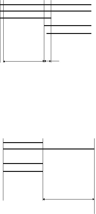
2.1 STARTING CYCLE Room thermostat
Burner Fan
Ignition Transformer
Fuel Valve
Photocell
Reset Lamp
TP 20 s |
TS 5 s |
The flame control unit starts the sequence of operation after a heating request (normal operation or thermostat operation) and it consists of the following steps:
•Self-test (less than 3 s): self-check of electronics efficiency;
•Purging time TP (20 seconds): fan motor and ignition transformer are simultaneously switched on while the fuel valve remains closed to eliminate any fuel or unburnt residual.
During the purging stage, the flame signal is constantly monitored for any kind of failure leading to combustion prevents the burner ignition.
In case of heating request off (room thermostat off), the control unit goes to stand-by position. The device remains in this status till closing of the room thermostat;
•Safety time (5 seconds): at the end of the purging time TP, the fuel valve is switched on and opens the fuel to the nozzle.
In case of flame detection failure by the end of the TS safety time, the control unit goes to lockout, and the fan motor, the ignition transformer and the fuel valve are de-energized, while the lockout signal is enabled.
Otherwise, at the end of the TS safety time the control unit disables the ignition transformer and goes to running position.
2.2 SHUT OFF CYCLE |
Room thermostat |
|
Burner Fan |
|
Ignition Transformer |
|
Fuel Valve |
|
Photocell |
|
Reset Lamp |
|
90 s |
When the heating request (normal operation or thermostat off or low) opens:
•fuel valve and ignition transformer are switched off and the flame lights off;
•burner fan operates a 90 s post-purge ventilation
Restoring the heating request causes the post-purge to be interrupted and the starting cycle to be performed.
4

2.3 FLAME FAILURE DURING STARTING CYCLE
Room thermostat
Burner Fan
Ignition Transformer
Fuel Valve
Photocell
Reset Lamp
TP 20 s |
TS 5 s |
If during the safety time TS, the photocell monitors a flame failure (signal to photocell becomes lower than minimum), at the end of safety time the unit goes in lock out condition:
•burner fan, ignition transformer and fuel valve are de-energized;
•alarm lamp on rest button becomes red
Unit can re-start only if pressing the reset button (3 seconds)
2.4 EXTRANEOUS LIGHT OR FLAME DURING PRE-PURGE TIME TP
Room thermostat
Burner Fan
Ignition Transformer
Fuel Valve
Photocell
Reset Lamp
TP 20 s
If during the pre-purge time the photocell monitors any residual flame then the unit goes in stand-by condition:
•burner fan goes on to purging combustion chamber
•fuel valve and ignition transformer are de-energized
•reset lamp is off;
5

2.5 FLAME FAILURE DURING RUNNING STATUS (ONE TRIAL RECYCLING)
Room thermostat |
|
Burner Fan |
|
Ignition Transformer |
|
Fuel Valve |
|
Photocell |
|
Reset Lamp |
|
TP 20 s |
TS 5 s |
|
90 s |
In case of flame failure in running status, the flame control unit make one trial restarting the unit.
If the reason of flame failure is confirmed, then the unit stops in lock-out mode, and the reset lamp becomes red.
2.6 RESET LAMP COLOR
! WARNING
The reset button may have different colours:
• 
 light off: unit is in stand-by status, waiting for heating request.
•  steady orange light : the heater stops temporarily to allow H/T/ transformer cooling down and automatically restarts when the time has passed
•  steady green light: unit is working normally (starting cycle or working cycle)
•  steady red light: the heater stops permanently in lock-out status and can restart only if reset button is pressed.
6
3. MAINTENANCE SCHEDULE
Periodic maintenance of the heater is necessary to ensure proper performance and to prevent failures and it shall be performed at the following periodic intervals:
•Daily maintenace
i.Inspect air inlet / air outlet and exhaust stack, remove debris if any
ii.If any air hose is installed, secure it. Minimize bends and keeps ducts straight
iii.Verify fuel tank is full
iv.Verify that exhaust stack is properly installed
•Weekly maintenance
i.Disassemble, inspect and clean fuel filter with clean fuel
ii.Remove top cover and clean the motor, fan blade and the interior shell
iii.Inspect the fuel hose assembly and check for any leaks
•6 months maintenance
i.Disassemble burner head
1.Inspect and clean burner diffuser
2.Inspect and replace nozzle as necessary
3.Clean ignition electrodes and adjust settings
4.Check air combustion setting
ii.Check overheat thermostat
iii.Inspect and clean the combustion chamber
iv.Open electric board, inspect electrical components and check connections
v.Check fuel pressure setting of fuel pump
vi.Inspect and test the burner
7
 Loading...