

Page 1
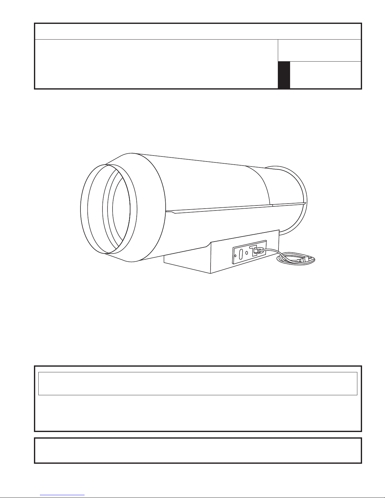
OPERATING INSTRUCTIONS AND OWNER’S MANUAL
READ INSTRUCTIONS CAREFULLY: Read and follow all instructions.
Place instructions in a safe place for future reference. Do not allow
anyone who has not read these instructions to assemble, light, adjust or
operate the heater.
HEATSTAR
BY ENERCO
MODEL
4000IDG
NATURAL GAS/LPG FIRED HEATER
WARNING:
— Do not store or use gasoline or other flammable vapors and liquids in the vicinity of this or any
other appliance.
— Service must be performed by a qualified service agency.
This is a vented portable heater. It uses air (oxygen) from the area in which it is used. Adequate
combustion air and ventilation must be provided. Refer to page 5.
If the information in this manual is not followed exactly, a fire or explosion
may result causing property damage, personal injury or loss of life.
01/10 #?????ENERCO GROUP, INC., 4560 W. 160TH ST., CLEVELAND, OHIO 44135 • 800-251-0001
Page 2
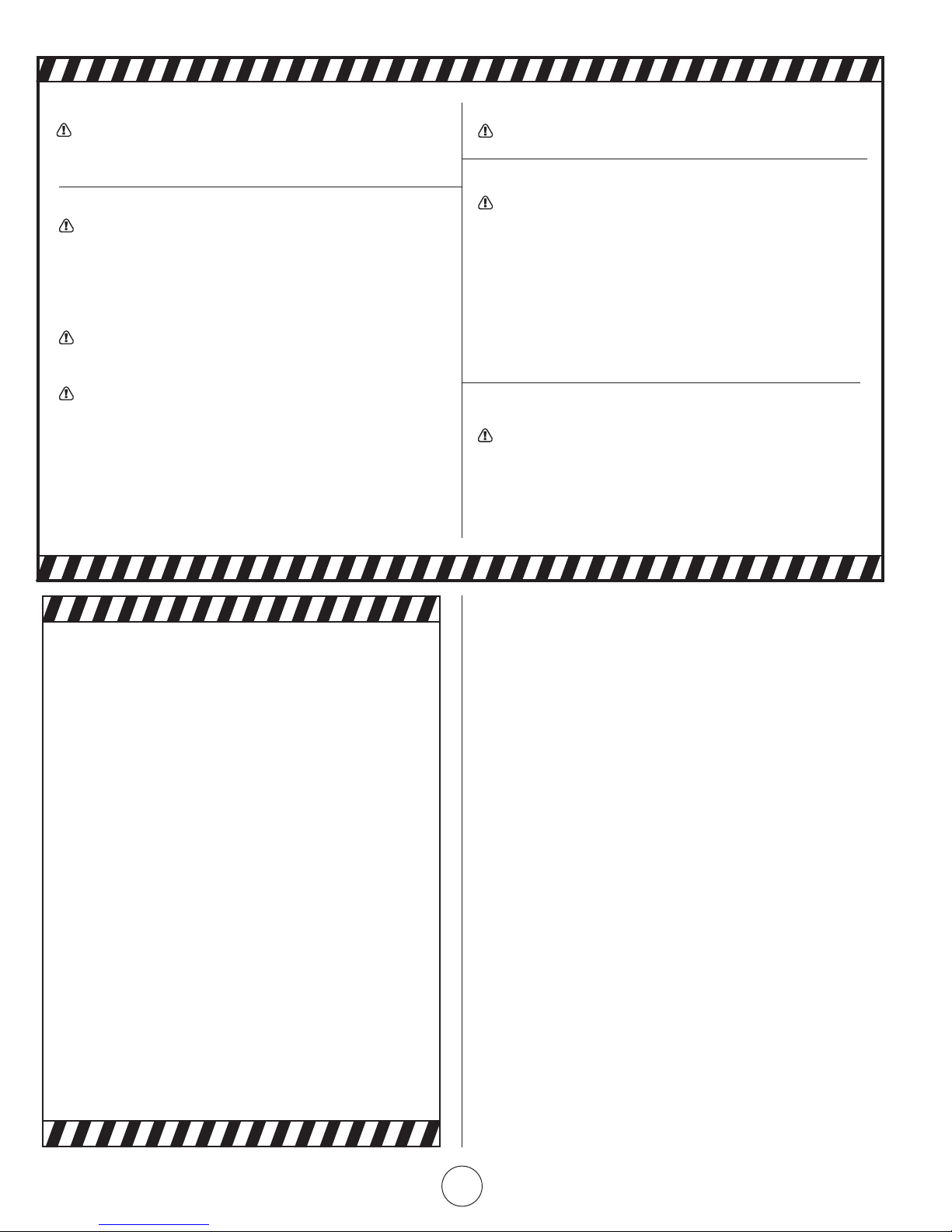
WARNING:
YOUR SAFETY IS IMPORTANT TO YOU AND TO OTHERS,
SO PLEASE READ THESE INSTRUCTIONS BEFORE YOU
OPERATE THIS HEATER.
GENERAL HAZARD WARNING:
FAILURE TO COMPLY WITH THE PRECAUTIONS AND
INSTRUCTIONS PROVIDED WITH THIS HEATER, CAN
RESULT IN DEATH, SERIOUS BODILY INJURY AND
PROPERTY LOSS OR DAMAGE FROM HAZARDS OF FIRE,
EXPLOSION, BURN, ASPHYXIATION, CARBON MONOXIDE POISONING, AND/OR ELECTRICAL SHOCK.
ONLY PERSONS WHO CAN UNDERSTAND AND FOLLOW
THE INSTRUCTIONS SHOULD USE OR SERVICE THIS
HEATER.
IF YOU NEED ASSISTANCE OR HEATER INFORMATION
SUCH AS AN INSTRUCTIONS MANUAL, LABELS, ETC.
CONTACT THE MANUFACTURER.
WARNING:
NOT FOR HOME OR RECREATIONAL VEHICLE USE
WARNING:
FIRE, BURN, INHALATION, AND EXPLOSION HAZARD.
KEEP SOLID COMBUSTIBLES, SUCH AS BUILDING MATERIALS, PAPER OR CARDBOARD, A SAFE DISTANCE
AWAY FROM THE HEATER AS RECOMMENDED BY THE
INSTRUCTIONS NEVER USE THE HEATER IN SPACES
WHICH DO OR MAY CONTAIN VOLATILE OR AIRBORNE
COMBUSTIBLES, OR PRODUCTS SUCH AS GASOLINE,
SOLVENTS, PAINT THINNER, DUST PARTICLES OR UNKNOWN CHEMICALS.
WARNING:
The State of California requires the following warning:
COMBUSTION BY-PRODUCTS PRODUCED WHEN US-
ING THIS PRODUCT CONTAIN CARBON MONOXIDE,
A CHEMICAL KNOWN TO THE STATE OF CALIFORNIA
TO CAUSE CANCER AND BIRTH DEFECTS (OR OTHER
REPRODUCTIVE HARM).
WARNING:
READ THE INSTRUCTIONS GIVEN IN THIS
MANUAL BEFORE USING THE APPLIANCE.
• THE ELECTRICAL SYSTEM TO WHICH THE APPLIANCE
IS CONNECTED MUST COMPLY WITH ALL SAFETY
REGULATIONS IN FORCE. A RESIDUAL CURRENT
CIRCUIT BREAKER MUST BE PROVIDED ON THE MAIN
DISTRIBUTION BOARD.
• UNPLUG THE HEATER BEFORE ATTEMPTING ANY
SERVICE OR MAINTENANCE.
• ALWAYS CHECK THE POWER SUPPLY CABLE BEFORE
USE. IT MUST NOT BE BENT, CRUSHED, OR ANYWAY
DAMAGED.
• THE POWER SUPPLY CABLE MUST BE REPLACED ONLY
BY QUALIFIED PERSONNEL.
• ONLY USE AN ORIGINAL H07RN-F POWER CABLE
WITH WATERPROOF PLUG.
• DO NOT TOUCH THE EXHAUST GAS OUTLET. DANGER
OF BURNS!
CONTENTS
WARNINGS .................................................................................. 2
SPECIFICATIONS ...........................................................................3
OPERATION ................................................................................. 4
SAFETY DEVICES ..........................................................................4
MAINTENANCE ............................................................................ 5
VENTILATION ............................................................................... 5
TROUBLESHOOTING .................................................................... 6
WIRING DIAGRAMS .....................................................................7
PARTS LIST ..................................................................................10
ENERCO GROUP, INC. |Indirect Fired Portable Heater Operating Instructions and Owner’s Manual
2
Page 3

IMPORTANT
Before using the heater, read and understand all instructions and
follow them carefully. The manufacturer is not responsible for
damages to goods or persons due to improper use of units.
GENERAL RECOMMENDATIONS
This indirect-red heater runs on natural gas or L.P.G. and is
fitted with a flue to take the fumes away through the chimney.
Prior to shipping, the heater is configured for either natural gas
or LP, labeled on the gas selector valve for the correct fuel type
and given a complete functional test. To change the type of gas,
follow the detailed instructions indicated in section “CHANGING
TYPE OF GAS”.
Always follow local ordinances and codes when using this
heater:
• Read and follow this owner’s manual before using the
heater.
• Use only in places free of ammable vapors or high dust
content.
• Never use heater in immediate proximity of ammable
materials (the minimum distance must be 6 ft.).
• Make sure re ghting equipment is readily available.
• Make sure sufcient fresh outside air is provided according
to the heater requirements. Direct combustion heaters
should only be used in well vented areas in order to avoid
carbon monoxide poisoning.
• The heater is installed near a chimney to take away the
fumes (see “Ventilation” on page 5) and connected to an
electrical switchboard.
• When the heater is connected to a ue pipe, the ue pipe
shall terminate in a vertical section at least 3 feet long and
sufficient draft shall be created to assure safe and proper
operation of the heater.
• Never block air inlet (rear) or air outlet (front).
• In case of very low temperatures add kerosene to the
heating oil.
• Make sure heater is always under surveillance and keep
children and animals away from it;
• Before starting the heater always check free rotation of
ventilator fan.
• Indirect red units only can be connected to air ducts to
distribute warm air, with respect to the max. static pressure
declared (see “TECHNICAL SPECIFICATION” sheet).
• Unplug heater when not in use.
TECHNICAL SPECIFIC ATIONS
Heat input [kBTU/h] 380
Air flow [cfm] 3,250
Heat output [kBTU/h] 328.7
Supply pressure [in WC]
Burner pressure [in WC] 6.40
Natural Gas
LPG
Power
supply
Electric consumption
Adjustment of combustion air flap [N] 3.0
Ring Nozzle [in]
Gas inlet connection thread [psi] 3/4” HPT
Flue [in] 5.91
Static pressure [in] 0.60
Compulsory flue draft [in] 0.05
Maximum air temperature [°F] 250
Base unit
Packaging
Fuel consumption [CFH] 355.97
Position of gas selector value
Supply pressure [in WC]
Burner pressure [in WC] 7
Fuel consumption [CFH] 133.89
Position of gas selector value
Phase 1
Voltage [V] 12 0
Frequency [Hz] 60
[W] 1400
[A] 13.0
Dimensions, L x W x H [in]
Weight [lb] 306
Dimensions, L x W x H [in]
Weight [lb] 3 61
HS 4000IDG
min 7’ w.c.
max 10” w.c.
min 8’ w.c.
max 13’ w.c.
N. 12 holes x
0.106”
72.3 x 31.6 x
30.4
74.1 x 26.0 x
35.83
Operating Instructions and Owner’s ManualENERCO GROUP, INC. |Indirect Fired Portable Heater
3
Page 4

INSTALLATION
WARNING
• All the operations described in this paragraph must be
performed by professional and skilled personnel
When equipped for Natural Gas, the installation shall conform
with local codes or, in the absence of local codes, with the Na-
tional Fuel Gas Code ANSI Z223.1/NFPA 54 and the Natural Gas
and Propane Installation Code, CSA B149.1.”
When equipped for propane
• The installation must conform with local codes or, in the ab-
sence of local codes, with the Standard for the Storage and
Handling of Liqueed Petroleum Gases, ANSI/NFPA 58 and
the Natural Gas and Propane Installation Code, CSA B149.1.
• Heater shall not be directed toward any propane/gas container within 6 m (20 feet)
• Size and capacity of gas cylinders shall be properly dimen-
sioned according to the gas flow in Tab.1
• The cylinder supply system shall be arranged to provide for
vapor withdrawal from the operating cylinder
• After having connected to gas cylinder, open the supply tap
and check the supply pipe and fittings for gas leaks. Only
use foam soap or an approved leak detector.
• The gas shall be turned off at the propane supply cylinder(s)
when the heater is not in use.
• When the heater is to be stored indoors, the connection
between the propane supply cylinder(s) and the heater must
be disconnected and the cylinders) removed from the heater
and stored in accordance with Standard for the Storage and
Handling of Liqueed Petroleum Gases, ANSI/NFPA 58 and
CSA B149.1, Natural Gas and Propane Installation Code.
GAS LINE CONNECTIONS
The connection to the gas feed pipe, whose sizes must correspond to the kind of system to be made, must be carried out by
placing the “gas ramp” as indicated in Fig. 2: the gas pipe (1), the
interception tap (2) and the anti-vibration joint (3) are not sup-
plied with the heater and they must be arranged by the person in
charge of installation.
Fig. 2
STARTUP
The heater is supplied after a complete functional test and it’s
therefore prearranged for one of the gas (natural or L.P.G.) indicated in Tab. I: an adhesive label applied on the gas selector valve
(13) indicates the working gas (usually it’s natural gas). Should it
necessary to change the kind of gas (from natural gas to L.P.G
or vice-versa) follow the detailed instructions indicated in section
“CHANGING TYPE OF GAS”.
Only when the heater has been prearranged according to the
proper working gas it will be possible to carry out the following
operations:
• Leak away some gas from the feed pipe;
• Check that the pipe is gas proof;
• Open the gas stopcock and start the hot air generator;
WARNING Never use free flames to detect gas leaks
ELECTRICAL CONNECTIONS
WARNING The power line of the generator must
feature an earth lead and a residual current circuit breaker.
The supply cable must be connected to a switchboard with
sectioning switch.
Every heater is supplied along with the safety and control devices
which are indispensable to the correct functioning of the unit being already electrically connected.
WARNING Electrical grounding shall be in compliance
with the National Electrical Code ANSI/NFPA 70 or the CSA
C22.1 Canadian Electrical Code, Part I.
The following operations must now be carried out:
• Plug in the power cord having read the rating plate that
specify electric supply characteristics.
• Connect accessories such as the room thermostat or clock
to the unit’s control panel with the thermostat receptacle.
Having completed all these operations check carefully that all
elec¬trical connections correspond to the wiring diagram. When
the heater is first turned on you must check that the fan does not
use more current than the maximum permitted limit.
CHANGING TYPE OF GAS
This operation may be carried out several times during the working life of the machine and not only at initial startup. Therefore,
first of all check the adhesive label attached to the gas selector
valve (13) in Fig. (1) to establish the original category of the gas
and then consult Tab. I to identify the supply pressure, the working pressure, the using conditions of manual valve.
To change kind of gas it is necessary (Fig. 3):
• to remove the sticker on the gas selector valve stating the
gas used at that time,
• to remove the screw under the sticker and turn the manual
handle on the correct side according to the condition described in Tab.I and by following instruction:
Fig. 3
• After having moved the handle into the opposite position,
put again the fixing screw and a new sticker on it, stating
the gas which has to be used (a number of different stickers
are supplied with the machine)
ENERCO GROUP, INC. |Indirect Fired Portable Heater Operating Instructions and Owner’s Manual
4
Page 5

WARNING Burner pressure shall not be adjusted: the
heater is ready to run on the new gas
Should it necessary to check the burner pressure:
• connect a manometer to the pressure port (14) ,
• carry out the pressure reading on the manometer and turn
the pressure regulator (15) if necessary to obtain the correct
burner pressure value indicated in Tab. I
OPERATING INSTRUCTIONS
SWITCHING ON
• Make sure switch (8) is on “0”;
• Power the heater by means of the sectioning switch on the
switchboard;
• If the unit is operated manually turn the switch (8) to
• The burner starts up, the combustion chamber heats up and
then the fan starts;
• If the unit operates automatically set the room thermostat
at the desired level and turn the control knob (8) to : the
heater will now start and stop automatically.
• If after these operations, the generator does not work, refer
to the “FAULTS, CAUSES AND REMEDIES” paragraph and
find the cause.
TURNING OFF
• In manual operation turn control knob (8) to “0” or turn off
control in automatic operation.
• After switching off the machine, a post ventilation time is
electronically set by a control flame box to lower the combustion chamber temperature (usually post ventilation lasts
for 90 sec).
• Stop the machine as indicated in the “STOP” paragraph;
• Disengage the power supply by removing the plug from the
power socket;
• Close the gas supply stopcock;
• Wait for the heater to cool down.
During cleaning any foreign bodies must be removed from the fan
suction grille.
WARNING Do not direct jets of compressed air
towards the air pressure points near the main fan: the air
pressure switch could be permanently damaged.
WARNING Finally, close the gas supply stopcock and
turn of the sectioning switch (Fig. 1).
VENTILATION
To obtain the ventilation effect only, simply turn the switch (8) to
the position marked by the symbol to start the machine. To stop
it, turn the switch to “O”/OFF (Fig. 1).
TRANSPORT AND HANDLING
The heater can be raised and hung up using the four anchor holes
on the casing.
WARNING Before moving the unit:
• Stop the machine as indicated in the “STOP” paragraph;
• Disengage the power supply by removing the plug from the
power socket;
• Fully unscrew the tting connecting the gas hose pipe to
the heater;
• Wait for the heater to cool down.
MAINTENANCE
To regulate operation of the unit, the fans, combustion chamber,
the burner must be periodically cleaned.
WARNING Before performing any maintenance
operation:
Operating Instructions and Owner’s ManualENERCO GROUP, INC. |Indirect Fired Portable Heater
5
Page 6

TROUBLESHOOTING
TROUBLE CAUSE SOLUTION
The heater fails to start No power supply Check power specifications Check power con-
nections Check fuse
Main switch in wrong position Select correct position
Faulty operation of room thermostat Check thermostat position Check thermostat
operation
Air pressure switch tripped due to fan malfunction
Air pressure switch tripped due to pressure
switch malfunction
The heater stops and the warning
light (1) comes on
The heater stops and then starts
again
Fan noise or vibrations Foreign bodies on fan blades Remove foreign bodies
The ionisation electrode does not detect a
flame
Safety thermostat tripped due to the combustion chamber overheating
Control unit tripped due to irregular burner
operation
Faulty electronic control unit Check the unit and if necessary replace it.
Faulty thermostat Check the thermostat and if necessary replace
Burner thermostat tripped Air distribution ducts too long or with insuf-
Little air circulation Eliminate all possible obstacles to proper air
Check that the suction and the flow grills are
unobstructed Check that the fan is running
freely Check the electric motor and the condenser and, if faulty, replace them
Replace the pressure switch
Remove the flame sensor and clean it
Check that the suction and the flow grills are
unobstructed Check that the room is well
ventilated Check that the hot air can escape
freely Check that the gas flow or pressure are
not excessive
Contact Service Assistance
it
ficient diameter
flow
If heater still not working properly, please revert to nearest authorized dealer.
ENERCO GROUP, INC. |Indirect Fired Portable Heater Operating Instructions and Owner’s Manual
6
Page 7

WIRING DIAGRAM
4000IDG SERIES MODELS
If any of the original wire as supplied with the
appliance must be replaced, it must be replaced
with type AWG 16 or AWG 18 wire or its equivalent
as by here specified.
AP CONTROL BOX
TA ROOM THERMOSTAT PLUG
ST ELECTRIC PILOT LAMP
FU FUSE
LI1 OVERHEAT THERMOSTAT
EV1 SOLENOID VALVE I° Stage
MB BURNER MOTOR
CO CONDENSER
MV FAN MOTOR
FUA FUSE
EV2 SOLENOID VALVE II° Stage
RV CONTROL
FA FAN THERMOSTAT
LF ANTI-JAMMING FILTER
IT TRANSFORMER H.V.
LI2 OVERHEAT SAFETY THERMOSTAT, LI2
SF FLAME LAMP
PA AIR PRESSURE SWITCH
EI IONISATION PROBE
Operating Instructions and Owner’s ManualENERCO GROUP, INC. |Indirect Fired Portable Heater
7
Page 8

4000IDG Series Indirect-Fired Heater
ENERCO GROUP, INC. |Indirect Fired Portable Heater Operating Instructions and Owner’s Manual
8
Page 9

4000IDG Series Indirect-Fired Portable Heater Parts List
1 G06185-9010 Outlet cone
2 G06290 Combustion chamber
3 G06187 Combustion chamber support
4 G06188-9010 Upper body
5 G06189-9010 Cover inspection
6 G06291-9010 Lower body
7 E10695-110 Motor 750W with condenser
8 E11242 Condenser 50 µF
9 G06191 Motor flange
10 T10267 Fan Ø550 18°
11 M20207 Whell holder Ø 14
12 G06192-9010 Air flap
13 P30151 Inlet grille
14 I31131 Conn. Straight Ø6 M5
15 I40337 Rilsan pipe Ø4x30 mm
16 I40335 Siliconepipe Ø4x8
17 PH.0020201 Ignition electrode
18 PH.0020202 Ionisation electrode
19 I40319 Silicone pipe Ø8x12
20 G02078 H.T. Cable connect. 90°
21 G06280 Blast tube
22 I40804 Air duct L=220 mm
23 E50104 Fan Thermostat
24 E50102 Limit Thermostat
25 M20107 Washer Ø5 x Ø15 x 1,5 mm
26 G06196 Centrifuge air fan
27 M20413 Bulb support
28 E50767 Thermostat TY95A 105 °C Campini
29 I20326 Connection 3/4”FF
30 I39106 Gas tube
31 G06277-9005 Lifting bracket
32 02AC535 Air intake
35 C30376 Cable protection Ø36 mm
36 G06282-9010 Base
37 G06193 Air adjustment panel
38 G06204 Air adjustment protection
39 G06288-9005 Valve support
40 C30323 Cable protection Ø20 mm
41 G06068-9005 Power lead hook
42 G00260 El. componets drawer
43 P50127 Control box cover
44 G06278-9005 Bottompanel
45 G06289 Electr. componets drawer
46 E20508 Fuse holder
47 E10324 Fuse (6x30)25A
49 E20319 Terminal board
50 E20305 Terminal board
51 E10931 Transformer H.T. BRHAMA
52 E40229 Control box BRAHMA TGRD 81-120V
53 G06073 Plate for electrical components
56 E20418 Stop button protection
57 E10102-P Switch 0 - 1
58 E20640 Thermostat plug 3P+T
59 E20675 Plate plug 90° 3P + T
60 E11032 Lamp
61 E30443 El. wire with plug and cable fastener
62 E11030 Lamp 230V
63 I31040 Nut 3/4”
64 M20130 Washer Ø28 x Ø40 x 2 mm
65 G06284 Burner ange Ø 102mm
66 PH.0020211 Connection 3/4” MF
67 M20315 Seeger ring E28
69 PH.0020205 Gas tube
70 PH.0020210 Diffusion ring - 12 holes Ø2,7 mm
71 I30661 Burner plate
72 M10323/1 Screw TCEI M4x20
73 I31132 Conn. Straight Ø7 1/8” F
74 T30217-115 Solenoid valve VE189HV-115V
75 G06287-9010 Solanoid valve/pressure switches
support
77 E50409 Pressure switches DUNGS LGW10A2
78 C30374 Drain plug
79 E11233 Condenser 20 µF
80 E10677-110 Motor 200W with condenser
81 G06200-9010 Support fan and motor
82 C10328 Connection channel
83 C30372 Cable protection Ø35 mm
84 G06201-9010 Support fan and motor
85 C10329 90° elbow connection
86 T10269 Fan AP 170x55 F12,7
87 C10326 Spiral fan
88 G06202 Shutter for air regulation
89 G06203 Air adjustment level
90 I39102 Seal 3/4”
91 I31205-1 Connection 3/4”MM
92 I20326 Connection 3/4”FF
97 T30111 Valve ELSTER VAD1T20N
100 E11229 Condenser 80 µF
101 G06227 Fitting support
102 M20907 Valve support
103 I31204 Connection 3/4”MM
10 4 T30330-1 Gas selector valve
Operating Instructions and Owner’s ManualENERCO GROUP, INC. |Indirect Fired Portable Heater
9
Page 10

OPERATING INSTRUCTIONS AND OWNER’S MANUAL
HEATSTAR
BY ENERCO
MODEL
4000IDG
READ INSTRUCTIONS CAREFULLY: Read and follow all instructions.
Place instructions in a safe place for future reference. Do not allow anyone
who has not read these instructions to assemble, light, adjust or operate
the heater.
WARNING:
USE ONLY MANUFACTURER’S REPLACEMENT PARTS. USE OF ANY OTHER PARTS
COULD CAUSE INJURY OR DEATH. REPLACEMENT PARTS ARE ONLY AVAILABLE
DIRECT FROM THE FACTORY AND MUST BE INSTALLED BY A QUALIFIED SERVICE
AGENCY.
PARTS ORDERING INFORMATION:
PURCHASING: Accessories may be purchased at any Mr. Heater/HeatStar local dealer
or direct from the factory
FOR INFORMATION REGARDING SERVICE
Please call Toll-Free 800-251-0001 • www.enerco-mrheater.com
Our ofce hours are 8:30 AM – 5:00 PM, EST, Monday through Friday.
Email to: techservice@enerco-mrheater.com
Please include the model number, date of purchase, and description of problem in all
communication.
LIMITED WARRANTY
The company warrants this product to be free from imperfections in material or workmanship,
under normal and proper use in accordance with instructions of The Company, for a period
of one year from the date of delivery to the buyer. The Company, at its option, will repair or
replace products returned by the buyer to the factory, transportation prepaid within said one
year period and found by the Company to have imperfections in material or workmanship.
If a part is damaged or missing, call our Technical Support Department at 800-251-0001.
Address any Warranty Claims to the Service Department, Enerco Group, Inc., 4560 W. 160TH
ST., Cleveland, Ohio 44135. Include your name, address and telephone number and include
details concerning the claim. Also, supply us with the purchase date and the name and address
of the dealer from whom you purchased our product.
The foregoing is the full extent of the responsibility of the Company. There are no other
warranties, express or implied. Specifically there is no warranty of fitness for a particular
purpose and there is no warranty of merchantability. In no event shall the Company be liable for
delay caused by imperfections, for consequential damages, or for any charges of the expense
of any nature incurred without its written consent. The cost of repair or replacement shall be
the exclusive remedy for any breach of warranty. There is no warranty against infringement of
the like and no implied warranty arising from course of dealing or usage of trade. This warranty
will not apply to any product which has been repaired or altered outside of the factory in any
respect which in our judgment affects its condition or operation.
Some states do not allow the exclusion or limitation of incidental or consequential damages, so
the above limitation or exclusion may not apply to you. This Warranty gives you specific legal
rights, and you may have other rights which vary from state to state.
Enerco Group, Inc. reserves the right to make changes at any time, without notice or obligation,
in colors, specifications, accessories, materials and models.
ENERCO GROUP, INC., 4560 W. 160TH ST., CLEVELAND, OHIO 44135 • 800-251-0001
Mr. Heater is a registered trademark of Enerco Group, Inc.
© 2004, ENERCO GROUP, INC. All rights reserved
ENERCO GROUP, INC. |Indirect Fired Portable Heater Operating Instructions and Owner’s Manual
10
01/10 #?????
 Loading...