

Eneo VKC-1425 Installation And Operating Instructions Manual
1
Installation and Operating Instructions
1/4” Camera, Day & Night, 23x Zoom
VKC-1425

2
Contents
1. Safety Instructions ......................................................................4
2. General Description ....................................................................
6
3. Rear View and Part Names .........................................................
7
4. Installation .................................................................................9
4.1 Connecting a Monitor ........................................................9
4.2 Connecting to Power .......................................................10
4.3 Camera Control Methods .................................................11
5. Communication Protocol ...........................................................
14
5.1 PELCO-D Byte Format ......................................................14
5.2 PELCO-P Byte Format ......................................................16
6. On-Screen Display ....................................................................
17
6.1 Explanation of the On-Screen Display ..............................17
7. Menu and Operation .................................................................
20
7.1 How to Set Up Functions..................................................20
7.2 Main Menu – FOCUS .......................................................22
7.3 Main Menu – EXPOSURE .................................................24
7.4 Main Menu – DAY/NIGHT (optional) ..................................26
7.5 Main Menu – BLC ............................................................27
7.6 Main Menu – WHITE BAL .................................................28
7.7 Main Menu – 3D-DNR .....................................................29
7.8 Main Menu – SPECIAL .....................................................30
7.9 Main Menu – GENERAL ...................................................35
7.10 Main Menu – INITIAL .......................................................38
7.11 Main Menu – EXIT ...........................................................39

3
Betriebsanleitung
Installation and Operating Instructions
Mode d’emploi
Instrukcja instalacji i obsługi
www.videor.com
www.eneo-security.com
⇒
8. Specifications ...........................................................................40
9. Dimensional Drawings ..............................................................
43

4
1. Safety Instructions
• Read these safety instructions and the operation manual first
before you install and commission the camera.
• Keep the manual in a safe place for later reference.
• Protect your camera from contamination with water and humidity
to prevent it from permanent damage.
Never switch the camera on when it gets wet. Have it checked at
an authorized service center in this case.
• Never operate the camera outside of the specifications as this
may prevent the camera functioning.
• Do not operate the cameras beyond their specified temperature,
humidity or power ratings.
Operate the camera only at a temperature range of -10°C to
+50°C and at a humidity of max. 90%.
• To disconnect the power cord of the unit, pull it out by the plug.
Never pull the cord itself.
• Pay attention when laying the connection cable and observe that
the cable is not subject to heavy loads, kinks, or damage and no
moisture can get in.
• The warranty becomes void if repairs are undertaken by
unauthorized persons. Do not open the camera housing.
• Never point the camera towards the sun with the aperture open.
This can destroy the sensor.
• Installation, maintenance and repair have to be carried out only by
authorized service centers.
Before opening the cover disconnect the unit from mains input.

5
• The fitter is responsible for the system of protection being
followed in accordance with the technical data, e.g. by sealing of
the cable outlet with silicone.
• Contact your local dealer in case of malfunction.
• Only use original parts and original accessories from
Videor E. Hartig GmbH.
• Do not use strong or abrasive detergents when cleaning the
dome. Use a dry cloth to clean the surface.
In case the dirt is hard to remove, use a mild detergent and wipe
gently.
• During assembly, care must be taken to ensure that existing
seals are correctly inserted and are not displaced as a result
of assembly.
You must not continue to use damaged seals.
NOTE: This is a class A digital device. This digital device can
cause harmful interference in a residential area;
in this case the user may be required to take
appropriate corrective action at his/her own expense.

6
2. General Description
• High Resolution Day&Night Camera
• Integrated 23x AF lens / 10x digital zoom
• True day&night mode with IR cut filter
• Adjustable video transmission distance (3 steps)
• Powerful digital noise reduction (3D DNR)
• Motion detection (MD)
• Low speed shutter control (DSS)
• Digital effects: H/V reverse, 180° rotate
• Privacy masking
• On-screen menu control (OSD)
• RS-485 serial interface (Pelco P & D)
Parts supplied
• Camera
• Camera socket with 4 screws
• Installation and Operating Instructions
7
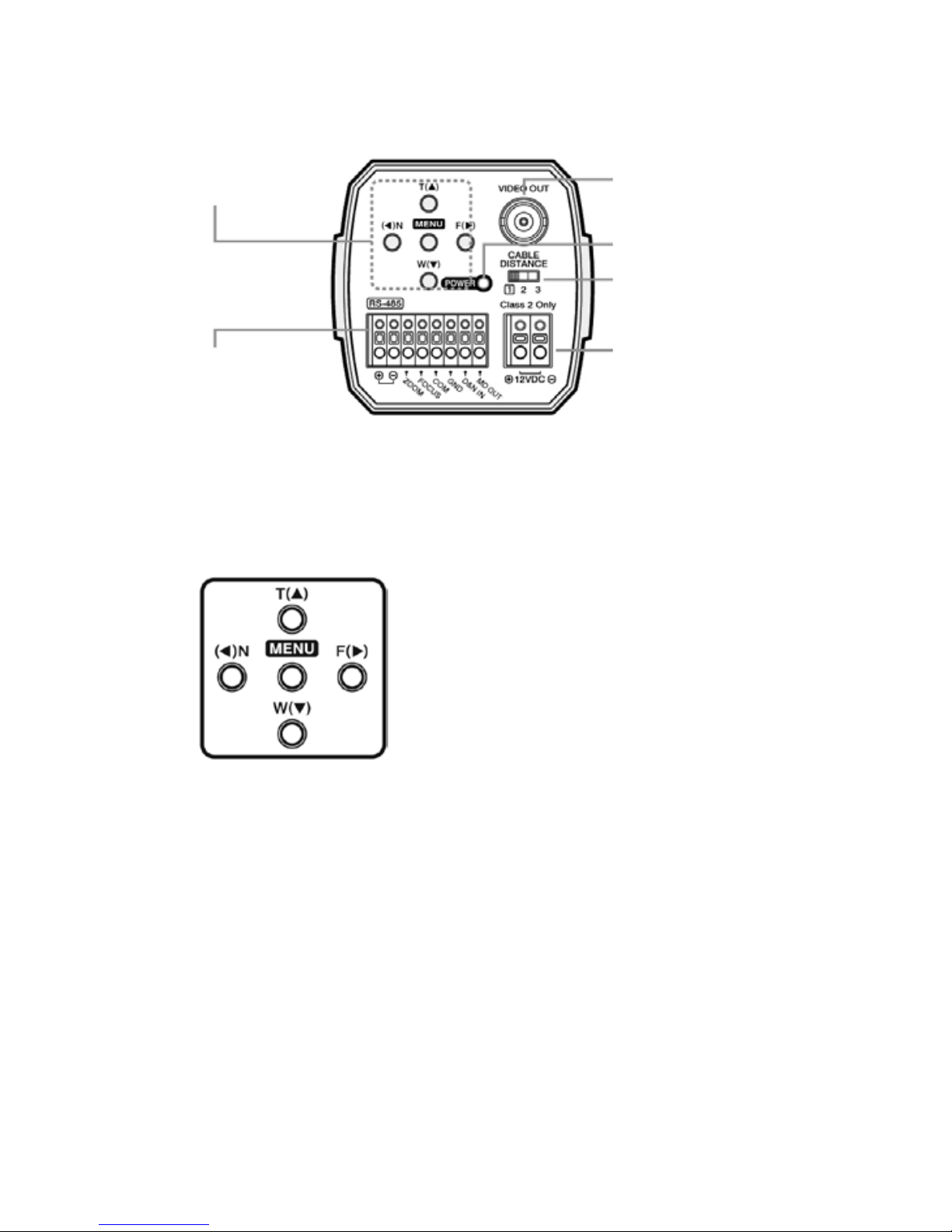
3. Rear View and Part Names
(5) Power Input Terminal
(2) Video Out Jack
(3) Power LED
(4) Selection Switch
(6) Control Terminal
(1) Function Setup
Button
1. Function Setup Button
Functions can be setup using 5 buttons on the camera’s rear panel.
2. VIDEO OUT Jack
Used to connect an external video monitor in jack
3. Power LED
The LED turns on when power is supplied.
• MENU Buttons: Used to access menu
mode. Also used to escape menu mode.
• TELE/WIDE Buttons: Used to choose
the desired menu item.
It also moves the cursor up or down in
the menu screen.
• NEAR/FAR Buttons: Used to change
the parameter of the selected menu
item. It also moves the cursor the left
of right in the menu screen.
8
4. Selection Switch
When the distance is far from camera to monitor, set „Selection
Switch” in 2 or 3. It shows more clear video on the monitor.
5. POWER Input Terminal
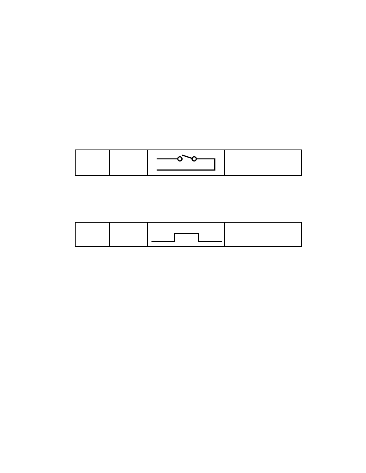
6. Control Terminal
• D&N IN: It is the function that can turn on external D&N mode
is set „EXT D&N” on the OSD menu of the camera.
D&N IN
GND
EXT Type
Open contact: Day
Close contact: Night
SW
MD OUT
GND
+5V
0V
+5V 10mA: Motion on
0V: Motion off
• MD OUT: It is the function that can turn on DVR recorder when
MD mode is set „ON” on the OSD menu of the camera.
9
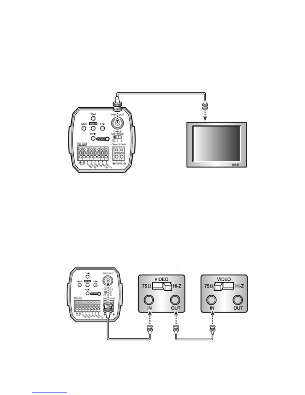
• Connect the camera after switching off each piece of equipment.
• Change the 75ohms/Hi-Z conversation switch of each piece of
equipment according to the following diagram - move the switch
of the intermediate monitor to Hi-Z, and the end equipment to
75ohms.
4. Installation
4.1 Connecting a Monitor
Connect the video out jack on the back of the product to the monitor
Monitor
Camera
Intermediate
Video receiver
End Equipment
Camera
10
• As voltage may drop according to the length of electric cord,
a camera may malfunction if too long output line of adaptor
is connected to the camera.
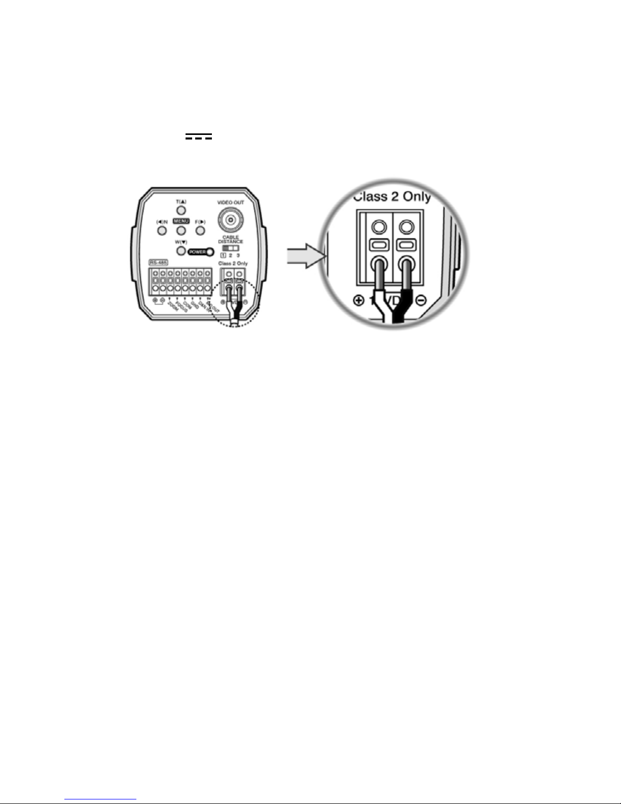
• Voltage for camera operation: 12VDC ±10%
4.2 Connecting to Power
• The wire is polarized. Be careful of polarity.
• Use 12VDC
power source.
11
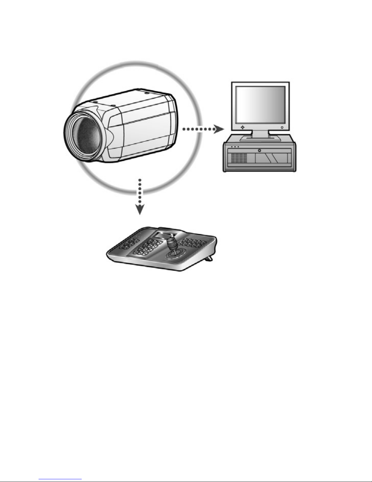
PTZ Controller
4.3 Camera Control Methods
Remote control using for PTZ controller
12
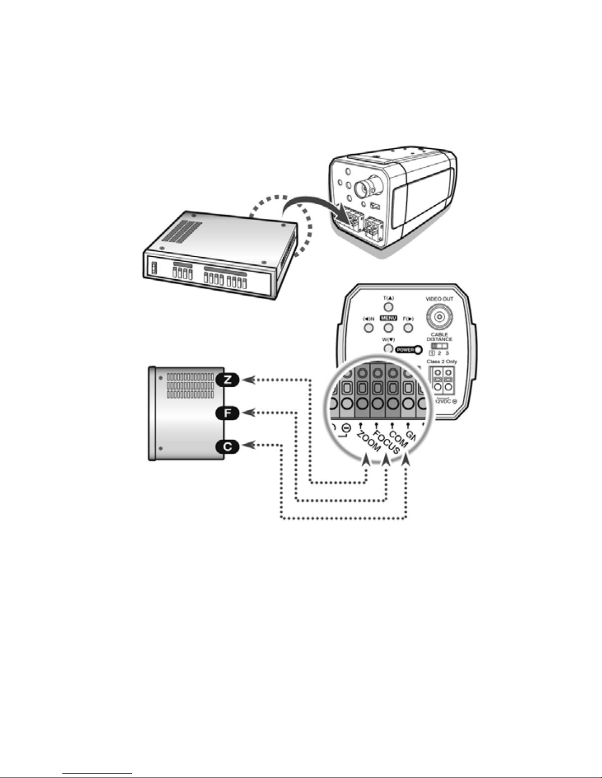
Remote control using for RS-485
Pelco-D Keyboard
DVR System
Signal (RS-485)

13
• Keyboard (Pelco-D, Pelco-P)
• DVR
Serial Cable
Camera RS-485 Converter
DVR - Connect to Serial PORT
(COM1 or COM2)
Pelco-D Keyboard

14
5. Communication Protocol
5.1 PELCO-D Byte Format
-RS-485, 9600bps, 1 start bit, 8 data bits, 1 stop bit, no parity
• Command Message
Function Zoom Tele
Byte 1 Byte 2 Byte 3 Byte 4 Byte 5 Byte 6 Byte 7
MSG
0xFF CamID 0x00 0x20 0x00 0x00 Checksum
Function Zoom Wide
Byte 1 Byte 2 Byte 3 Byte 4 Byte 5 Byte 6 Byte 7
MSG
0xFF CamID 0x00 0x40 0x00 0x00 Checksum
Function Focus Near
Byte 1 Byte 2 Byte 3 Byte 4 Byte 5 Byte 6 Byte 7
MSG
0xFF CamID 0x01 0x00 0x00 0x00 Checksum
Function Focus Far
Byte 1 Byte 2 Byte 3 Byte 4 Byte 5 Byte 6 Byte 7
MSG
0xFF CamID 0x00 0x80 0x00 0x00 Checksum
Function Menu On / Off
Byte 1 Byte 2 Byte 3 Byte 4 Byte 5 Byte 6 Byte 7
MSG
0xFF CamID 0x40 0x00 0x00 0x00 Checksum
Function Power On
Byte 1 Byte 2 Byte 3 Byte 4 Byte 5 Byte 6 Byte 7
MSG
0xFF CamID 0x88 0x00 0x00 0x00 Checksum
Function Power Off
Byte 1 Byte 2 Byte 3 Byte 4 Byte 5 Byte 6 Byte 7
MSG
0xFF CamID 0x08 0x00 0x00 0x00 Checksum
Function Pelco D Stop
Byte 1 Byte 2 Byte 3 Byte 4 Byte 5 Byte 6 Byte 7
MSG
0xFF CamID 0x00 0x00 Don’t care Checksum
 Loading...