

Eneo VBQ-6045 Operating Instructions Manual

1
Betriebsanleitung
S/W und Farb-Video Quad Splitter
Modellreihe: VCQ-6057, VBQ-6045
Operating Instructions
B/W and Colour Video Quad Splitter
Model Series: VCQ-6057, VBQ-6045
Mode d’emploi
Quadravision noir/blanc et couleur
Série: VCQ-6057, VBQ-6045
Instrucciones de manejo
Quad Splitter Video en B/N en color
Series de modelos: VCQ-6057, VBQ-6045

2
3
Inhaltsverzeichnis
1 Sicherheitshinweise/Pege ...............................................................2
2 Mitgeliefertes Zubehör.......................................................................3
3 Technische Merkmale........................................................................3
4 Lage und Funktion der Bedienelemente............................................3
A Frontseite......................................................................................3
B Rückseite .....................................................................................4
5 Installation..........................................................................................6
5.1 Grundsätzliches Verkabelungsschema
mit Alarm Ein-/Ausgang ................................................................6
5.2 VCR-Wiedergabe...........................................................................7
5.3 Videorekorder-Anschluss für Aufzeichnung und
Start/Stop-Betrieb.........................................................................7
5.4 Montage des 19”-Einschub-Winkelsets.........................................8
5.5 Fernsteuerungs-Anschluss............................................................9
6 Bedienung...........................................................................................9
6.1 Bildschirm-Menü .........................................................................9
6.2 Quad-Darstellungs-Modus .........................................................12
6.3 Vollbild-Darstellung ....................................................................12
6.4 Standbild-Darstellung der Kamerabilder (FREEZE) ......................12
6.5 Alarm Einstellungen ...................................................................13
6.6 Sequenzieller Umlauf ..................................................................13
6.7 VCR-Betrieb ...............................................................................14
7 Fernbedienbetrieb ............................................................................14
7.1 Belegung der 9-pol. D-Sub-Buchse ............................................14
7.2 ASCII Steuercodes.......................................................................15
8 Zubehör.............................................................................................16
9 Technische Daten ............................................................................17
Anhang ....................................................................................................35
1 Sicherheitshinweise / Pege
• Bevor Sie das Gerät anschließen und in Betrieb nehmen, lesen Sie bitte
zuerst die Sicherheitshinweise und die Betriebsanleitung.
• Bewahren Sie die Betriebsanleitung für spätere Verwendung sorgfältig auf.
• Die Lüftungsschlitze des Gerätes niemals abdecken.
• Das Gerät gegen Eindringen von Wasser und Feuchtigkeit schützen.
Sollte dennoch Feuchtigkeit eingedrungen sein, das Gerät nie unter
diesen Bedingungen einschalten und zur Überprüfung an eine qualizierte
Servicestelle geben.
• Den Deckel des Gerätes nicht öffnen.
Instandsetzung nur durch qualiziertes Servicepersonal.
• Das Gerät nur in einem Temperaturbereich von 0 bis +50°C und einer
Luftfeuchtigkeit bis max. 90% betreiben.
• Niemals metallische oder andere Gegenstände durch die Lüftungsschlitze
stecken, dies könnte das Gerät dauerhaft schädigen.
• Das Gerät ist vor großer Hitze, Staub, Feuchtigkeit und Vibrationsein wirkung zu schützen.
• Die Belastung des Gehäuses durch schwere Gegenstände ist zu
vermeiden.
• Zur Reinigung des Gerätegehäuses nur ein mildes Haushaltsmittel
verwenden. Niemals Verdünner oder Benzin benutzen. Dies kann die
Oberäche dauerhaft schädigen.
Contents
1 Safety Instructions / Cleaning ..........................................................2
2 Supplied Accessories ........................................................................3
3 Features .............................................................................................3
4 Operating Control and their Functions .............................................3
A Front Panel ..................................................................................3
B Rear Panel ...................................................................................4
5 Installation Notes ...............................................................................6
5.1 Basic System Connection with Alarm
Inputs and Outputs .......................................................................6
5.2 VCR Connection for Zoom on Playback Operation..........................7
5.3 VCR Connection for Tape Record Start and Stop Control ...............7
5.4 Use of Rack Mount Kit ..................................................................8
5.5 Remote Control Connection ..........................................................9
6 Operating ............................................................................................9
6.1 The Setup Menu ...........................................................................9
6.2 The Quad Display Mode .............................................................12
6.3 The Full Screen Display Mode ....................................................12
6.4 The Still Frame Display Mode (FREEZE) ......................................12
6.5 Alarm Operations .......................................................................13
6.6 The Auto-Sequence Mode ..........................................................13
6.7 VCR Operations ..........................................................................14
7 Remote Control Operations..............................................................14
7.1 Pin Assignment of the 9 pin D-Sub Connector ............................14
7.2 ASCII Command Codes ...............................................................15
8 Accessories .....................................................................................16
9 Technical Data .................................................................................18
Annex ... ...................................................................................................35
1 Safety Instructions / Cleaning
• The following instructions are for your own safety and should be
observed without fail.
• Please read these safety and operating instructions before putting the
system into operation.
• Keep the operating instructions in a safe place for later use.
• Do not block the ventilation slots.
• To prevent re or shock hazard, do not expose this appliance to rain,
water, wet locations. Should any liquid or solid object fall into the cabinet,
unplug the unit and have it checked by the qualied personnel before
operating it any further.
• Do not remove the screws of the cover. Refer servicing to qualied
service personnel.
• Use the quad unit under conditions where temperature is within 0°C to
50°C and humidity is below 90%.
• Do not drop foreign materials such as water, liquid or metallic parts
through slots. This action could permanently damage the quad unit.
• Keep away from heating elements and do not expose to wet, dust and
vibration conditions.
• Do not place heavy items on the quad unit.
• Do not use strong or abrasive detergents when cleaning the units body.
Use a dry cloth to clean the cabinet when dirty. In case the dirt is hard
to remove, use a mild detergent and wipe gently.
3
VCQ-6057 Farbe (Colour)
VBQ-6045 S/W (B/W)
2 Mitgeliefertes Zubehör
• Netzadapter 230VAC / 12VDC
• Betriebsanleitung
3 Technische Merkmale
• Hochauösende Quadbild-Kombination von vier S/W- oder Farbkamera signalen zur Wiedergabe und Aufzeichnung im Real-Time Modus.
• Manuelle oder sequenzielle Vollbild-Darstellung aller Kamerasignale, oder
des Quadbildes, auf dem Monitorschirm.
• Uhrzeit-/Datums- und Kameratitel-Anzeige für jeden Kanal sowie
Bildschirm-Programmierung
• Einfache Tasten-Bedienung
• Alarm-Auslösung durch externe Kontakte, bzw. bei der Unterbrechung
eines Kamerasignal-Einganges
• Vollbilddarstellung der alarmierten Kamera und Einschaltung eines ex ternen Aufzeichnungs-Gerätes, (z.B. VCR). Einstellbare Alarm-Haltedauer
• Eingebauter akustischer Alarmgeber (abschaltbar)
• Der Ausfall einer Videosignalquelle, durch einen Kameradefekt oder eine
Kabelunterbrechung, bewirkt das „Einfrieren” des letzten an diesem
Eingang angekommenen Bildes.
• Keine synchronisierten Kameras erforderlich
• Fernsteuerung mittels Fernbedienung oder PC, über eine RS-232-Schnitt stelle
4 Lage und Funktion der Bedienelemente
A Frontseite
2 Supplied Accessories
• 230VAC / 12VDC Adapter
• Operating instruction manual
3 Features
• Four B/W or colour camera outputs can be combined into one video signal
for simultaneous display and recording.
• User selected video display mode including quad display mode
(cameras 1-4) and full screen sequential switching.
• On-screen time/date, title display for each channel, and on-screen
set-up menu
• Simple push-button operation
• Alarm detection for sensor contact closure and video loss in camera
inputs
• Alarm called full screen display with VCR start/stop and external alarm
duration control
• Built-in buzzer for alarm detection acknowledgement
• Freeze of last picture before video loss
• Does not require special cameras or synchronization.
• Remote control/RS-232 control through keypad or PC
4 Operating Control and their Functions
A Front Panel
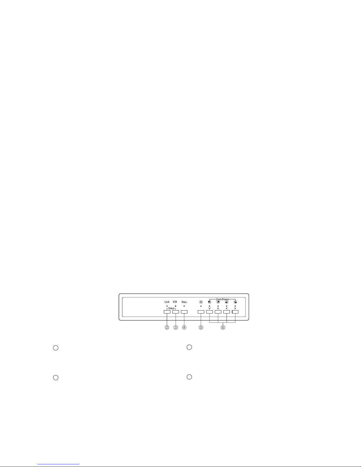
2 Verriegelung (Lock)
Durch Drücken der Taste Lock, für die Dauer von mind. 2 sek., wird die
frontseitige Bedienung gesperrt. Eine erneute Betätigung der Taste für 2 sek.
hebt die Sperrung wieder auf.
3 VCR-Wiedergabe/Zoom-Funktion (VCR)
Zur VCR-Wiedergabe ist diese Taste zu betätigen. Bei gedrückter Taste sind
„Sequenz, Quadbild und Kanalauswahl” unwirksam.
2 Lock
Security lock-out button. Push this button for 2 seconds to enable control
panel lock-out function. Push this button again for 2 seconds to disable the
function.
3 VCR
Press this button for VCR-play back. In this mode, the output video is
displaying the video signal from VCR.
4
5
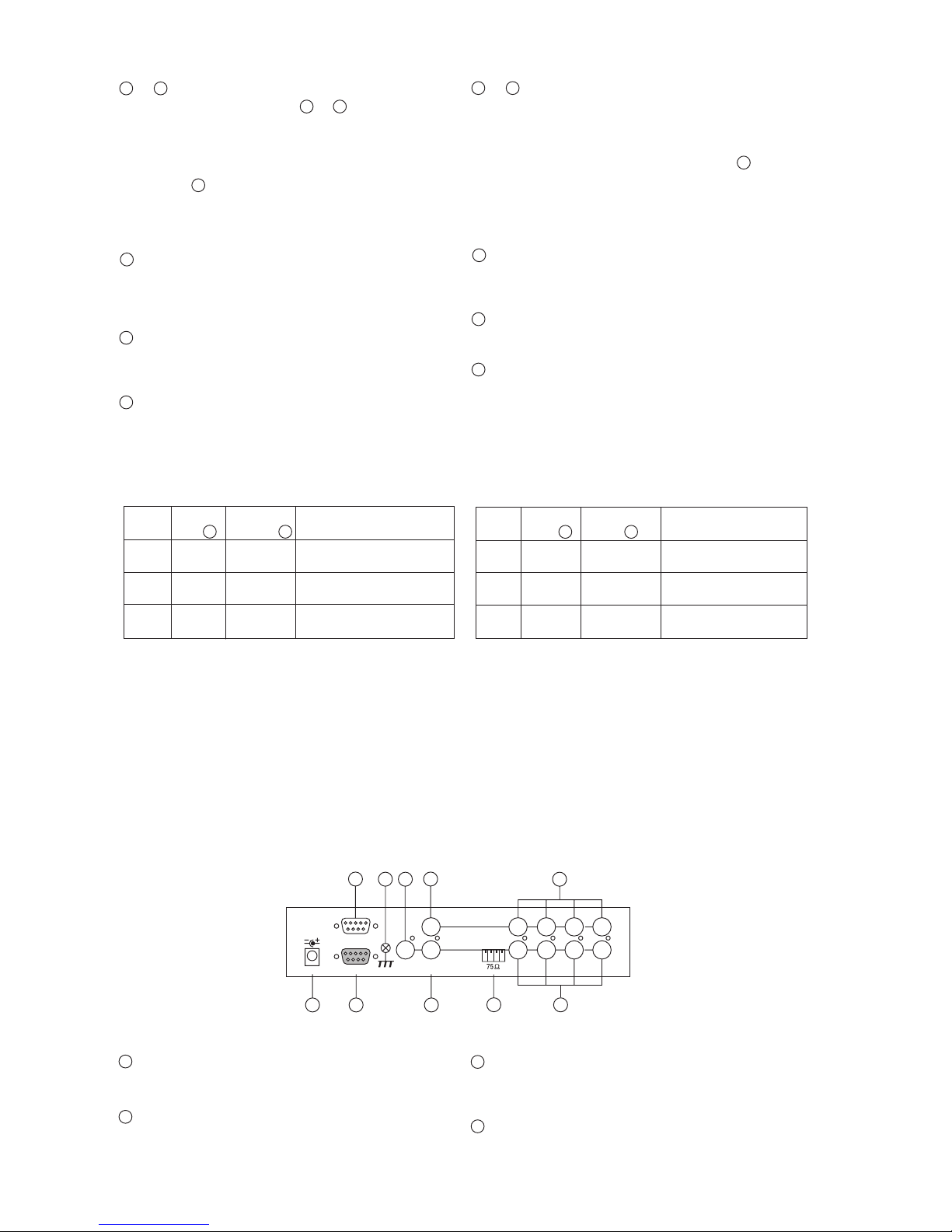
B Rear Panel
2 and 3 Menu
Push these two buttons simultaneously to get into menu setup mode and
display page 1 of system setup menu. Push these two buttons simultaneously again to display page 2 of the setup menu. Use page 1 to program
time/date, dwell time and camera title and page 2 to congure alarm
operations. Under menu setup mode, channel select buttons 6 are used for
cursor control and text selection to program the setup menu. Push the setup
buttons simultaneously again to save the setting.
Push the setup buttons to save the setting and push the buttons to get back
to ordinary operation mode.
4 Sequence
Push this button to enable full page auto sequencing mode. Push this button
again to disable it.
5 Quad Display
Push this button to switch between quad/full screen display mode.
6 Channel Select Buttons, FREEZE
When operated in full screen display mode, these buttons are used to select
specic camera to be displayed in full screen.
When operated in quad mode, these buttons are used to freeze any specic
camera by pushing the corresponding button.
2 und 3 Bildschirm-Menü
Durch gleichzeitiges Betätigen der Tasten 2 und 3 gelangt man zur Seite
1 des Bildschirm-Menüs. Eine weitere, gleichzeitige Betätigung der beiden
Tasten lässt die Seite 2 erscheinen.
Auf Seite 1 werden die Funktionen: Uhrzeit/Datum, Verweildauer und Kameratitel eingegeben, Seite 2 dient zur Konguration der Alarmverarbeitung.
Über die Tasten 6 wird der Cursor bewegt (s. Symbole über den Tasten) und
die einzugebenden Textzeichen ausgewählt. Eine weitere Betätigung beider
Tasten speichert die programmierten Daten, nach einer erneuten Betätigung
gelangt man in die normale Betriebsart zurück.
4 Sequenzschaltung, Vollbild-/Halbbildschaltung
Durch Betätigung der Taste Sequence wird in den automatischen Umlauf geschaltet, d.h. die Bilder aller angeschlossenen Kameras werden sequenziell
im Vollbild-Modus gezeigt.
5 Quadbild-Wiedergabe
Die Betätigung dieser Taste bewirkt die Umschaltung zwischen Quadbildund Vollbild-Wiedergabe.
6 Standbild- / Kameraanwahl-Tasten, FREEZE
Im Vollbild-Modus bewirkt das Betätigen der Tasten die Anwahl des entsprechenden Kameraeinganges.
Ausgehend vom Quadbild-Modus werden, durch Betätigung dieser Tasten, in
den jeweiligen Quadranten Standbilder erzeugt (Einfrieren).
B Rückseite
VCQ-6057
VBQ-6045
hi-z
1 2 3
4
DC 12V 1amp
RS-232
ALARM I/O
in
out
15
9
8
10
11
13
16
17
12
monitor
vcr
7
Die v.g.Tasten dienen auch zur Cursor-Bewegung sowie Text-Zeichenauswahl im Bildschirm-Menü.
These buttons are also used as cursor control and text select keys under
setup menu mode.
Video Quad- Kanal-An- Funktion
Freeze Taste 5 wahltaste 6
EIN EIN EIN Das Quadrantenbild wird einge froren.
EIN AUS EIN Darstellung des eingefrorenen
Bildes im Vollbild-Modus
AUS EIN/AUS EIN Darstellung des Kameraeinganges
im Vollbild-oder Quad-Modus
Video Quad Channel select Function
Freeze button 5 buttons 6
ON ON ON Freeze specic camera video
in quad screen mode
ON OFF ON Call up specic camera input
in Freeze mode
OFF ON/OFF ON Call up specic camera input
in Full screen mode
7 Erdungs - Anschluss
Vorgesehen zum Anschluss der Betriebserde.
8 Spannungsversorgung
Anschluss des mitgelieferten Netzadapters (12VDC)
7 Chassis GND
This contact is provided to ground the chassis to the Earth Ground to prevent
interference and electrical shock.
8 Power Input
Power input connector. Use DC 12VDC

5
9 Fernbedienungs-/RS-232 - Anschluss
Anschluss für die jeweils vorgesehene Fernbedienung (s. Abschnitt 8/Zubehör), bzw. zur Geräte-Konguration über einen PC (s. Abschnitt 7).
10 Alarm-Eingang (Alarm in)
9-pol. D-Sub-Buchse für den Anschluss der Alarm Ein-/Ausgangs-Kontakte.
Als Alarm-Ausgang ist ein Relais-Umschaltkontakt vorhanden.
Pin - Belegung des Alarmanschlusses
Pin-Nr. Pin-Nr. Pin-Nr.
1 Eingang 1 4 Eingang 4 7 Schliess-Kontakt
2 Eingang 2 5 Reset 8 Gemeinsam
3 Eingang 3 6 Masse 9 Öffner-Kontakt
9 Remote/RS-232 Connector
This 9 pin D-sub connector is used to provide remote control operation via
the appropriate remote keypad (see section 8/Accessories) or a PC.
Please refer to section 7 for more details.
10 Alarm In
This 9 pin D-sub connector is used for alarm sensor input and alarm output
control connections. It provides Normally open and Normally closed contacts
for alarm out control.
Pin assignment for alarm connector
Pin # Pin # Pin #
1 Sensor 1 4 Sensor 4 7 Normally open contact
2 Sensor 2 5 Reset 8 Common contact
3 Sensor 3 6 GND 9 Normally closed contact
11 Eingangs-Abschluss
Impedanz-Schalter für jeden Kamera-Eingang, schaltet zwischen 75Ohm
und HI-Z Impedanz. Ein falscher Abschluss setzt die Qualität des Videosignals
herunter. Der Abschluss ist werkseitig auf 75Ohm gesetzt.
12 Videoeingänge
BNC-Eingänge zum Anschluss der Kameras 1-4.
Im Quad-Modus werden die vier Eingänge wie folgt dargestellt:
11 Terminations
These impedance switches are used to provide proper termination for each
camera input. These switches toggle between 75ohms and Hi-Z impedance.
Incorrect termination will degrade the quality of the video signal. All video
inputs not „looped through” to another device, the corresponding switches
need to be set to 75ohms termination position. If another device is connected
to video out loop through connector, set the corresponding termination
switch to Hi-Z position. Any device connected to the video out loop through
connectors needs to be congure to 75ohms. video termination. The factory
default termination setting is 75ohms.
12 Video IN Connectors
These BNC connectors are used to connect to the video out from camera.
Total four cameras can be connected to form a quad screen in the following
mapping position. It is very important that each camera be correctly terminated. Please refer to Termination (#12) for proper impedance setting for
each video in connector.
13 Video Out
Video out loop through connectors: These connectors are used to loop video
signals from each camera out to other devices.
15 VCR In
This BNC connector is to be connected to the „video out” from your VCR. A
pre-recorded quad screen video can be played back from the VCR and pass
through to be displayed on the Monitor out 17 from this unit. This connector
also allows user to display and program the on screen menu of the connected VCR without reconnecting the cables.
16 VCR Out
This BNC connector is to be connected to the „video in” from your VCR.
It will only provide a quad screen video to ensure an un-interrupted video
recording for all four cameras. The display video is not affected by the
control panel and alarm status of the unit.
17 Monitor Out
This BNC connector is to be connected to the „video in” of your monitor. It
displays live video from camera inputs under live mode and playback video
from VCR under VCR mode. The live video displayed here can be in quad
screen, full screen, and auto sequencing mode depending on the operation.
1 2
3 4
13 Videoausgang
BNC-Ausgangs-Buchsen zum Duchschleifen der Kamerasignale zu anderen
Geräten.
15 VCR-Eingang (VCR IN)
BNC-Buchse für den Anschluss des Videorecorder-Ausganges. Dies ermöglicht das Anzeigen und Programmieren des Menüs eines angeschlossenen
Videorekorders.
Durch Betätigen der Taste 3 auf der Frontseite, schaltet man die Geräte auf
die Betriebsart „VCR-Wiedergabe” um.
16 VCR-Ausgang (VCR OUT)
BNC-Buchse für den Anschluss des Videorekorder-Einganges. Es werden
immer alle 4 Kameras aufgezeichnet. Die Aufzeichnung wird von der Bildwahl über die Fronttastatur nicht beeinusst.
17 Monitor-Ausgang (LIVE)
BNC-Buchse für den Anschluss an einen Monitor-Eingang zur Wiedergabe
von Live-Bildern. Die Live-Bilder können als Quadbild, Vollbild oder in
sequenzieller Darstellung erfolgen.
6
7
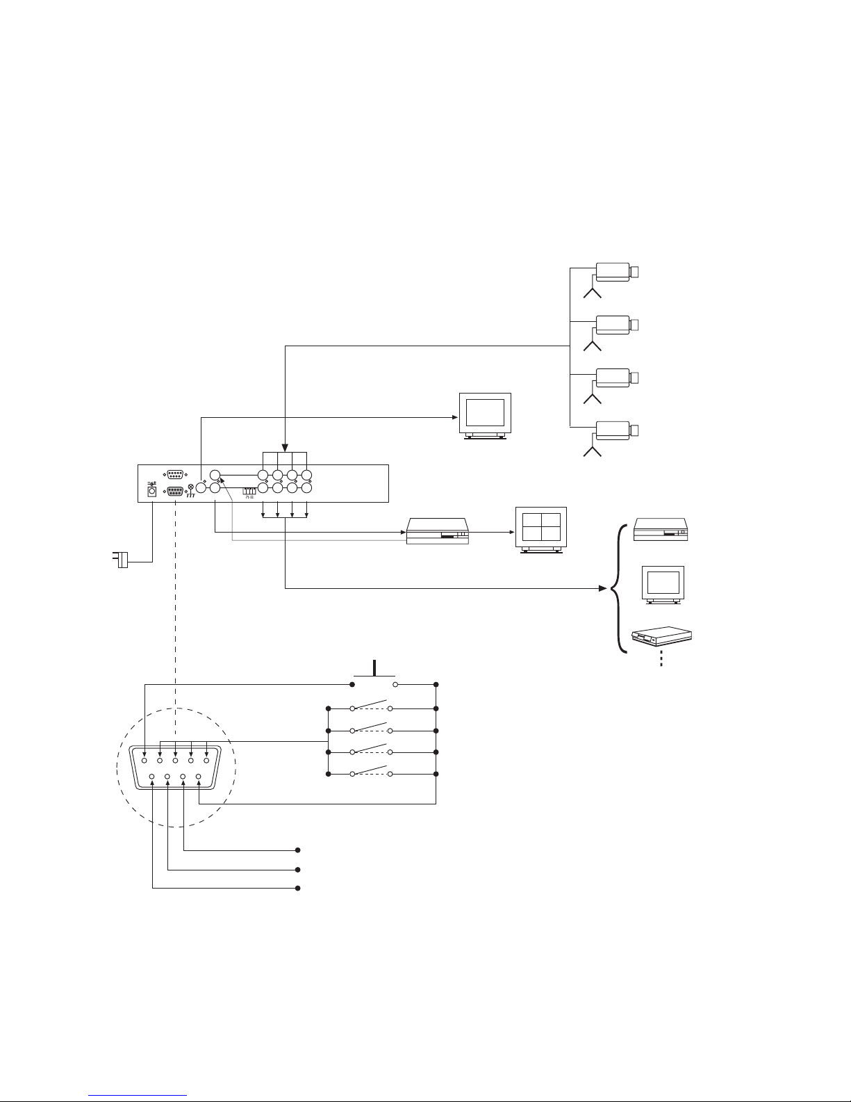
5 Installation Notes
It is essential that your system be properly hooked up for proper results. Use
the following diagram to install your system. Please power-off the unit before
installation.
5.1 Basic System Connection With Alarm Inputs and
Output
Hi-Z
1 2 3 4
DC 12V 1amp
Remote or RS-232
ALARM
in
out
monitor
vcr
ch1 ch2 ch3 ch4
1
6
VCR
Monitor
Processor
Camera 1
Camera 2
Camera 3
Camera 4
VCR
Quad-Darstellung
Quad display monitoring
Monitor
AC Adapter
Alarm reset
sen. 1
sen. 2
sen. 3
sen. 4
NO: Normaly open (Schliesser)
COM: Common (gemeinsam)
NC: Normaly closed (Öffner)
NO
COM.
NC
Video out
to Monitor
Quad
VCR in
to VCR
5 Installation
Vor der Installation Ihrer Anlage lesen Sie bitte auch die Betriebsanleitungen
der anderen, für das System vorgesehenen Geräte. Der Quad-Splitter sollte,
erst nach der Verkabelung aller Einheiten, an die Spannungsversorgung
angeschlossen werden.
5.1 Grundsätzliches Verkabelungsschema mit Alarm
Ein-/Ausgang
7
1
6
NO
COM
NC
t
Hi-Z
1 2 3
4
DC 12V 1amp
Remote or RS-232
ALARM
in
out
monitor
vcr
ch1 ch2 ch3 ch4
VCR
Recorder SW
COM.
Stop SW
Recorder
SW
Stop
SW
Alarm trigged
start recording
NO ––> NC
Recording stop
COM. (GND or VCC)
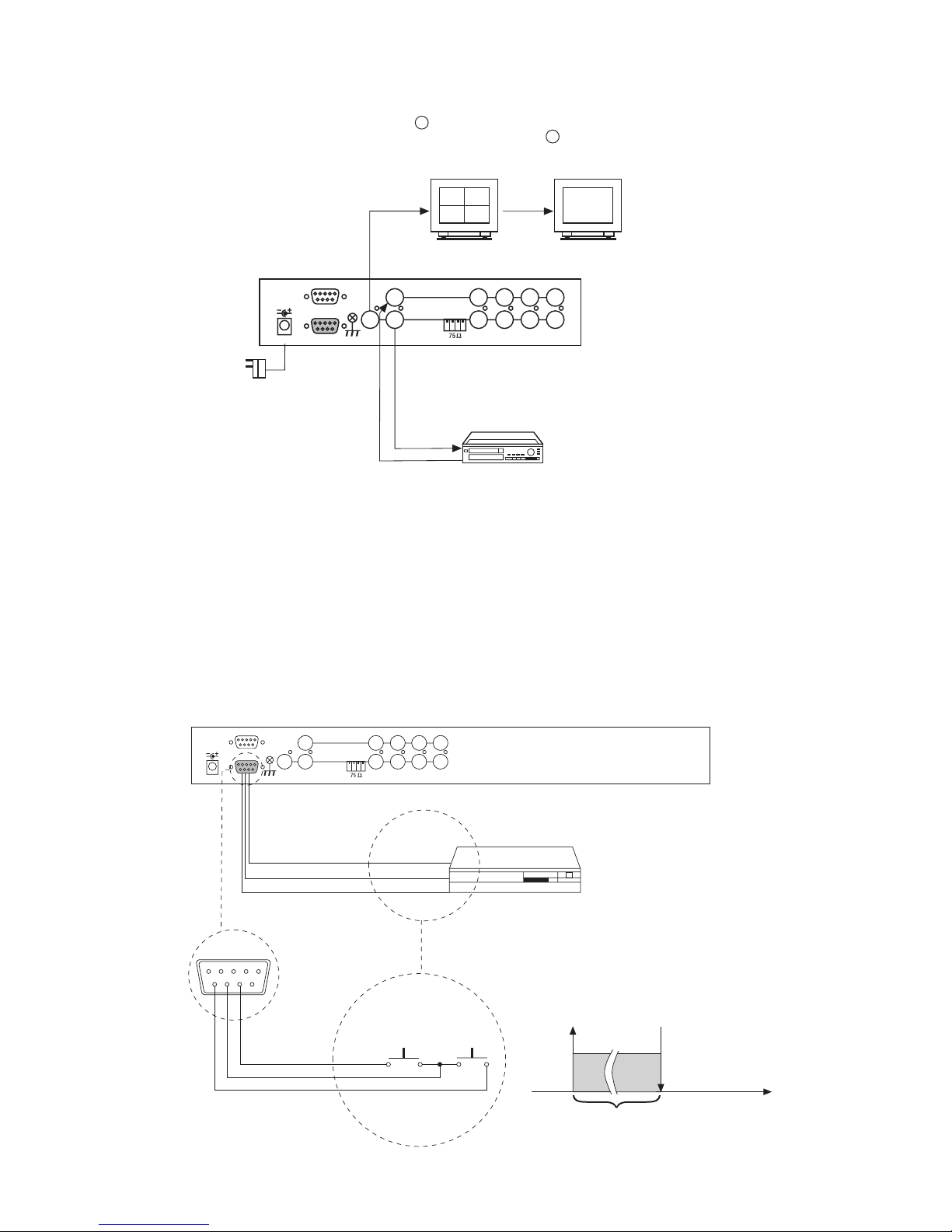
5.3 Videorekorder-Anschluss für Aufzeichnungs- und
Start/Stop-Betrieb
Für den automatischen Aufzeichnungsbetrieb auf einen VCR sind die
Fernsteuerungs-Funktionen „Aufzeichnung” und „Stop” des VCR mit den
Ausgangskontakten des Quad-Splitters zu verkabeln. Die Aktivierung eines
Alarm-Kontaktes löst die VCR-Aufzeichnung für die Dauer des Alarmzustandes aus.
• Stehen mehrere Alarme gleichzeitig an, wird das Bild der zuletzt
aktivierten Kamera aufgezeichnet.
• Sollen ausschließlich Vollbilder aufgezeichnet werden, ist der Rekorder Eingang mit dem Anschluss LIVE zu verbinden. Es wird jeweils das Bild
der zuletzt aktivierten Kamera aufgezeichnet.
5.3 VCR Connection for Tape Recording Start and Stop
Control
Connecting the contacts of VCR’s RECORD and STOP switch to the alarm
output NC and NO contacts will allow you to use an ordinary VCR to record
for longer period of time. Combined with alarm sensor detection, the VCR
will record only when an alarm sensor is activated.
• If more than one sensor have been trigged, VCR will start to record after
the last trigged event.
• In order to make use of the alarm called full screen display function the
VIDEO IN connector from the VCR has to be connected to LIVE monitor
connector of the device. If more than one sensor are trigged, VCR will
then record all the events in full screen mode accordingly.
5.2 VCR-Wiedergabe
VCR-Wiedergabebetrieb, zur Darstellung und Vergrößerung aufgezeichneter
Quad-Bilder (Zoom-Funktion). Durch Betätigung der VCR-Taste 3 auf der
Frontseite der Geräte gelangt man in diesen Modus.
5.2 VCR Connection for Zoom on Playback Operation
VCR playback mode is designed to play pre-recorded quad screen video and
display in either quad screen or expand any quadrant to full screen. Push
VCR button 3 in the front panel to switch to VCR playback mode.
hi-z
1 2 3
4
DC 12V 1amp
RS-232
ALARM I/O
in
out
monitor
vcr
Video in
Video out
Video in
Video out
Quad-Bild / Quad display 2fache Vergrößerung für jeden Quadranten /
2x expansion for any quadrant
VCR
AC Adapter
8
9
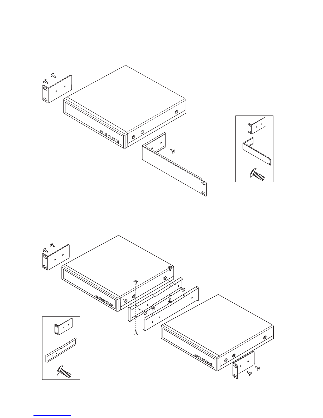
5.4 Montage der Einschub – Winkelsets
Siehe auch Abschnitt 8/Zubehör
5.4 Use of Rack Mount Kit
1/2 19" Winkelset für den Einbau eines Einzelgerätes 1/2 19" Rack mount kit for one unit
1x
1x
4x
2x
2x
14x
1/2 19" Winkelset für den Einbau von zwei Geräten 1/2 19" Rack mount kit for two units
9
1 2
3 4
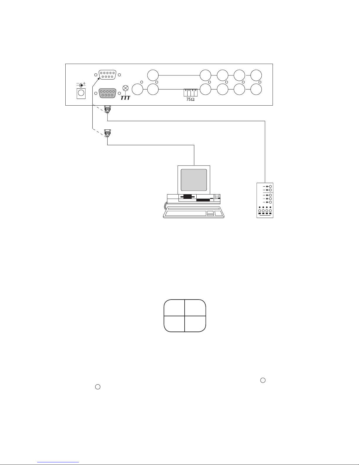
5.5 Fernsteuerungs - Anschluss
Rückfront
5.5 Remote Control Connection
Rear panel
hi-z
1 2 3
4
DC 12V 1amp
RS-232
ALARM I/O
in
out
monitor
vcr
Fernbedienung /
Remote keypad
6 Bedienung
6.1 Bildschirm-Menü
Nach dem Einschalten des Gerätes zeigt der Monitor (Anschluss 17) die aktuellen Einstellungen. Der Monitor zeigt die Bilder der vier angeschlossenen
Kameras im Quad-Modus.
6 Operating
6.1 The Setup Menu
Right after the unit is turned on, monitor connector 17 on the rear panel will
display the last setting on the setup menu. The Monitor always displays
4 cameras in quad screen mode as follows:
^
^
^
^
6.1.1 Seite 1 des Bildschirm-Menüs
(Anzeige-Programmierung)
Es können zwei Menü-Seiten angewählt werden.
Seite 1 ist für die Programmierung von Verweildauer, Uhrzeit/Datum und
Kameratitel vorgesehen, Seite 2 für die Konguration der Alarmverarbeitung.
Mittels der Anwahltasten 6 wird der Cursor bewegt und die Selektion der
Textzeichen vorgenommen. Zum Bewegen des Cursors werden die mit den
Zeichen < und > gekennzeichneten Tasten benutzt, für die Auswahl der
Textzeichen die Tasten „ ” und „ ”.
6.1.1 Page 1 of the Setup Menu (Display Setting)
There are two pages in the Setup Menu.
Page 1 is used to program DWELL TIME, TIME, DATE, camera TITLE, and
other display settings. Page 2 is used to program Alarm Operations.
Under this mode, channel selection buttons 6 on the front panel are used
for cursor control and text selection. Use the cursor control buttons „<” and
„>” to move the cursor to the entry in the menu desired to program, and
use the text select buttons „ ” and „ ” to choose the right alphanumeric
character to program.

10
11
Seite 1:
Programmierung von Zeit/Datum/Kameratitel und Bild-Intervallzeit
CH TITLE DWELL TIME
QUAD 03 S
1 __CH _1_ 03 S
2 __CH _1_ 03 S
3 __CH _1_ 03 S
4 __CH _1_ 03 S
VIDEO FREEZE ON
VIDEO OUT: LIVE/MONITOR QUAD/VCR
TITLE: ON ON
TIME: 08 : 10 : 10 ON ON
DATE: 04 –01 - 2000 ON ON
6.1.1.1 TITLE Setup
The title menu permits the setup of separate titles for each video channel.
Eight characters may be entered for each video channel. The available
alphanumeric characters are:
0, 1, 2, 3, 4, 5, 6, 7, 8, 9, ...
A, B, C, D, ... X, Y, Z
a, b, c, d, ... x, y, z
:, <, >, -, x, /, ?, space.
6.1.1.2 DWELL Time Setup
The Dwell time menu permits setting the dwell time for all cameras and the
quad screen on the Live output channel. The menu shows a table of all
cameras and associated dwell time. Dwell time can be programmed by
setting a number between 00 to 99 for each channel in the menu.
• -01 through 99: Adds the camera input to the auto switching sequence,
with the corresponding dwelll time in seconds
• -00: Skips the camera input in the auto switching sequence.
6.1.1.3 FREEZE
This entry is used to enable or disable the video freeze operation.
1. If this entry is set to ON, user can freeze the specic camera video under
live quad display mode by pressing corresponding channel buttons on the
front panel. However, user can only call up specic camera if the unit is
operated under full screen display mode.
2. If this entry is set to OFF, there will be no video freeze function. Under this
mode, the unit will only call up specic camera in live full screen display
by pressing corresponding channel buttons regardless the original display
mode of the unit.
6.1.1.4 TIME/DATE Setup
Time and date information can be displayed on the video output channel
through both Live and Quad connector. Bottom of page 1 is used to set the
values of time and date and also to enable or disable the display at each
output channel.
The time will display in the HH:MM:SS format and the date will display in
the MM-DD-JJ-Format.
6.1.1.5 TITLE/TIME/DATE Disable and Enable in Live and
Quad Video Output Channel
The title/time/date display on each output channel can be enabled or
disabled by setting ON or OFF in the corresponding entry.
6.1.2 Page 2 of the Setup Menu (Alarm Setting)
Push setup buttons 2 simultaneously again to display page 2 of the setup
menu on the screen. This alarm setting menu is used to set the desired
alarm conguration like sensor type, sensor sensitivity, alarm hold duration
and buzzer.
6.1.1.1 Einstellung des Kameratitels (TITLE)
Für jeden Kamera-Kanal kann eine bis zu 8-stellige Bezeichnung eingegeben
werden. Die verfügbaren Zeichen sind in der folgenden Tabelle gezeigt:
0, 1, 2, 3, 4, 5, 6, 7, 8, 9, ...
A, B, C, D, ... X, Y, Z
a, b, c, d, ... x, y, z
:, <, >, -, x, /, ?, space.
6.1.1.2 Einstellung der Bild-Intervallzeit (DWELL TIME)
Einstellung der Bild-Intervallzeit (Verweildauer) für jeden Kamera-Kanal
sowie des Quadbildes im automatischen Umlauf, für den Monitor-Ausgang.
Das Bildschirm-Menü zeigt die Nummern aller Kamera-Kanäle und die
dazugehörige Verweildauer, die zwischen 00 bis 99 sek. eingegeben werden
kann.
Einstellungen:
• -01 bis 99: Kamera-Kanal ist im automatischen Umlauf enthalten, das Bild
wird für die angezeigte Dauer (in Sek.) wiedergegeben.
• -00: Kamera-Kanal wird im automatischen Umlauf nicht berücksichtigt
(übersprungen).
6.1.1.3 Einfrieren (FREEZE)
Bei Stellung EIN kann das aktuelle Bild im Vollbild- oder Quad-Betrieb eingefroren werden. Bei Stellung OFF ist die Funktion „Einfrieren“ deaktiviert.
6.1.1.4 Einstellung von Uhrzeit und Datum (TIME/DATE)
Die Anzeige von Uhrzeit und Datum kann sowohl auf dem Monitor eingeblendet werden. Der untere Bereich des Bildschirm-Menüs ist für die Eingabe
der Zeit/Datums-Information sowie auf welchem Monitor die Wiedergabe
erfolgen soll, vorgesehen. Die Anzeige erfolgt im Format: Stunden : Minuten
: Sekunden (HH:MM:SS) für die Uhrzeit und Monat-Tag-Jahr (MM-DD-JJ)
für das Datum.
6.1.1.5 Anzeige von Uhrzeit/Datum/Kameratitel Ja/Nein
Ob und auf welchem Ausgang die einzelnen Anzeigen eingeblendet werden
sollen, wird durch das Setzen von ON, bzw. OFF für jeden Ausgangs-Kanal
bestimmt.
6.1.2 Seite 2 des Bildschirm-Menüs (Konguration der
Alarmverarbeitung)
Um auf die Seite 2 des Bildschirm-Menüs zu gelangen die Taste 2 betäti-gen. Diese Seite ist für das Kongurieren der Alarmverarbeitung, wie
Kontakt-Typ, Ansprech-Empndlichkeit, Alarmdauer, akustische Alarmgabe,
Videoverlustalarm und Videoverlustrelais vorgesehen.

11
6.1.2.1 Kontakt-Typ (SENSOR TYPE)
Das Gerät erkennt selbsttätig die Art des an jedem Kanal vorhandenen
Kontakt-Typs. Das Resultat wird in der Tabelle für jede Kanal-Nr. angezeigt:
OPEN für Schließkontakt-, CLOSE für Öffnerkontakt-Typ. In der nächsten
Spalte der Tabelle kann ein gewünschter Kontakt-Typ je Kanal eingegeben
werden. NO steht dabei für Schließkontakt, NC für Öffnerkontakt. In der
darauffolgenden Spalte wird eingegeben, ob der jeweilige Kontakt in die
Alarmverarbeitung einbezogen werden soll, oder nicht (STATUS). ON steht
für eine Einbeziehung, OFF unterdrückt sie. Die letzte Spalte zeigt, ob der
gewünschte Kontakt-Typ mit dem tatsächlich vorhandenen übereinstimmt.
Ist dies nicht der Fall, wird in der betreffenden Zeile ein blinkendes ? gezeigt
und beim Verlassen der Menü-Seite ertönt ein akustisches Signal.
6.1.2.2 Ansprech-Empndlichkeit (SENSITIVITY)
Das Gerät reagiert nur dann auf eine Alarmauslösung, wenn die Kontaktgabe
für eine bestimmte, einstellbare Zeitdauer erfolgt.
Eine Einstellung kann zwischen 0,2; 0,3; 0,4 und 0,5 sek. erfolgen.
6.1.2.3 Alarmhaltezeit (DURATION)
Die Alarmdauer kann zwischen 00 sek. bis 99 min. eingestellt werden.
Durch Anwahl von „>>” kann die Alarmdauer auf unendlich gesetzt werden.
In dieser Betriebsart kann ein ausgelöster Alarm nur durch Verbindung des
Alarm-Rücksetzkontaktes mit Masse zurückgesetzt werden.
6.1.2.4 Akustische Signalisierung (BUZZER)
Das Gerät verfügt über einen eingebauten Signalton-Geber, um einen
detektierten Alarm akustisch zu signalisieren. Im Feld BUZZER kann diese
Alarmsignalisierung durch Setzen auf OFF unterdrückt werden.
6.1.2.5 Videoausfall-Alarm (V-LOSS ALARM)
Mit dieser Einstellung kann die Signalisierung eines Videosignalausfalls
aktiviert oder deaktiviert werden. Das Gerät detektiert automatisch jeden
Videosignalausfall an jedem Eingang, wenn diese Option auf ON steht. Der
Anwender kann diese Funktion durch Einstellung auf OFF deaktivieren, um
Anwendungen zu ermöglichen, die eine ständige Videoquellenumschaltung
erfordern, wie z. B. Videokonferenz-Schaltungen.
6.1.2.6 Videoausfall-Relaissteuerung (V-LOSS RELAIS)
Das Gerät verfügt über ein alarmgesteuertes Relais, das sowohl durch
Alarmauslösungen von einem Sensor, wie auch durch Videoausfallalarm
aktiviert werden kann. In dieser Einstellung kann vom Benutzer die Aktivierung des Relais durch einen Videosignalausfall an einem beliebigen
Kameraeingang deaktiviert werden.
6.1.2.1 Sensor Type
The unit will rst detect the type of the sensor connected to the corresponding channel. The result will be displayed in the rst column following
each channel number. They can be on either OPEN or CLOSE. The menu
then allows user to enter a desired type of the sensor for each channel in
next column. NO means Normally Open, NC means Normally Close. Then the
menu will allow user to enable or disable sensor input for each channel in
the next column. ON will enable the contact to detect the alarm status from
the input. OFF will ignore the sensor input and disable the alarm detection
from the input. Last column on this part of the menu shows the result of the
actually detected sensor type and the desired conguration. If the setup type
of the sensor is different from the actually connected type of sensor, a
blinking ? message will be displayed. In this case, the buzzer will be
activated when you exit the setup operation.
6.1.2.2 Alarm Sensitivity
Alarm sensitivity can be programmed to different extent by setting the
period of the triggered pulse detected by the sensor.
The available settings are from 0.2; 0.3; 0.4 to 0.5 sec.
6.1.2.3 Alarm Hold Duration
The alarm hold duration can be set from 0 second to 99 minutes.
The duration can be set to non-stop by choosing „>>”. In this mode, the
activated alarm can only be reset by connecting the alarm reset contact to
ground.
6.1.2.4 Buzzer
The device has a built-in buzzer to signal a detected alarm by an audio tone.
User can choose to disable the buzzer by setting it to OFF.
6.1.2.5 Video Loss Alarm
This entry is used to enable or disable the video loss alarm. The device automatically detects loss of video at any input if this entry is set to ON. User can
choose to disable this feature by setting it to OFF for applications like video
conferencing or others that will need constant video source switching.
6.1.2.6 Video Loss Relais
The device is equipped with an alarm controlled relay, which can be activated by both sensor trigged alarm and video loss alarm. This entry allows
user to disable the relay activation from a loss of video in any camera input.
CH SENSOR TYPE STATUS
1 OPEN NO ON?
2 OPEN NO ON?
3 OPEN NO ON?
4 OPEN NO ON?
SENSITIVITY: 0.3 S
DURATION: 30 S
BUZZER: ON
V-LOSS ALARM: ON
V-LOSS RELAY: ON
ALARM SETTING
 Loading...