

Eneo TVR-2008AM1.0, TVR-2016AM1.0 Quick Installation Manual

Quick Installation Guide
Hybrid Video Recorder
HD-TVI, 1920x1080, 960H, SD,
TVR-2008AM1.0
TVR-2016AM1.0
EN
1
About This Document
This document contains instructions for DVR configuration and operation.
Package Contents
The package contains the following:
Digital Video Recorder
Power Cord
Quick User Guide (This Document)
Software CD (User’s Manual included)
Rack-moun t Kit
Assembly Screws for Adding Hard Disk Drives
SATA Cables
Infrared Remote Control
Notice
Specifications are subject to change without prior notice.
The information contained herein is to be considered for reference only.
The software included in this pro duct co ntains so me O pen So urces . You may obt ain the compl ete cor respo nding
source code from us. See the Open Source Guide on the software CD (OpenSourceGuide\OpenSourceGuide.pdf).
Warning
WARNING
RISK OF ELECTRIC SHOCK
DO NOT OPEN
WARNING: TO REDUCE THE RISK OF ELECTRIC SHOCK,
DO NOT REMOVE COVER (OR BACK).
NO USER-SERVICEABL E PARTS INSIDE.
REFER SERVICING TO QUALIFIED SERVICE PERSONNEL.
The lightning flash with arrowhead symbol, within an equilateral triangle, is intended to alert the user
to the pres ence of u ninsulated "danger ous voltag e" within the prod uct’s enclos ure that may be of
sufficient magnitude to constitute a risk of electric shock.
The exclamatio n point within an equilat eral tria ngle is int ended to aler t the user t o the pres ence of
important oper ating an d mainten anc e (servi cing) ins tru ction s in the li tera ture a cco mpa nying t he app l iance.
Symbol
Publication
Description
IEC60417, No.5032
Alternat ing curre nt

2
Important Safeguards
1. Read Instructions
All the safety and operating instructions should be read before the appliance is operated.
2. Retain Instructions
The safety and operating instructions should be retained for future reference.
3. Cleaning
Unplug t his e qui pment f rom the w all outlet before cleaning it. Do not use liquid aerosol cleaners. Use a damp
soft cloth for cleaning.
4. Attachments
Never add any attachments and/or equipment without the approval of the manufacturer as such additions may
result in the risk of fire, electric shock or other person al injury.
5. Water and/or Moisture
Do not use this equipment near water or in contact with water.
6. Placement and Accessories
Do not place this equipment on an unstable cart, stand or table. The equipment may fall, causing serious injury
to a child or adult , and serious damage to the equipment.
This equipmen t and cart combination should be moved wit h care. Quick stops, exc essive force, and uneven
surfaces ma y cau se the equipment and car t combination to overt urn.
Do not place this e quipme nt o n a cl os ed space . S uff icie nt amo un t of ve ntila tion a ir is nece s sary to avo id incr e ase
of ambient temperature which can cause improper operation or the risk of fire.
7. Power Sources
This eq uipment should be o perated on ly from the type of power source indicated on the marking label. If you
are not sure of the type of power, please consult your equipment dealer or local power company.
You may want to install a UPS (Uninterruptible Power Supply) system for safe operation in order to prevent
damage ca use d by an unex pect ed pow e r s topp ag e. A ny que stio ns co nce rni n g U PS , co ns ult your UPS r e tail er .
8. Power Cords
Operator or installer must remove power and TNT connections before handling the equipment.
9. Lightning
For adde d pr otection fo r th i s equipment during a lig ht ning storm, o r when it is left unattended and unused for
long pe rio ds o f tim e , unplug i t fr om the w al l o utle t an d dis con ne ct t he a nte nna o r ca ble sy ste m . T his w ill pr event
damage to the equi pment due to lightnin g and power-line surges.
10. Overloading
Do not overload wall outlets and extension cords as this can result in the risk of fire or electric shock.
11. Objects and Liquids
Never push objects of any kind through openings of this equipment as they may touc h dangerous vol t age points
or short out parts that cou l d r esult in a fire or electric shock. Never spill liquid of any kind on the equipment.
12. Servicing
Do not attempt to service this equipment yourself. Refer all servic ing to qualified service personnel.
13. Damage requiring S ervice
Unplug this e quipm e nt fr om the w a ll out le t and r ef e r se rvicing to qual if ie d se rvice pe rso nnel unde r the f ollowing
conditions:
A. When the po wer-supply cord or the plug has been damaged.
B. If liquid is spi lled, or object s have fallen into the equipment.
C. If the equipment has been exposed to rain or water.
D. I f the equipment doe s not operate no r mally by following the operating instructions , ad j ust o nly those controls
that are c ove red by the o per ating inst ructio ns as an im pro per adjus tme nt of othe r controls may result in damage
and will ofte n requir e e xtensiv e wo rk by a qual ifie d tech nician to re sto re the e quipme nt to its norm al ope ratio n.
E. If the equipment has been dropped, or the cabinet damaged.
F. W hen the equipment exhibits a distinct chang e in performance ─ this indicates a need for service.

3
14. Replacement Parts
When re pl a cement parts are r equired, be sur e t he se rvice technician has used re pl a cement parts specified by the
manufacture r o r that hav e the same characteristics as the original par t . Unauthoriz ed substitut ions may re s ul t
in fire, electric shock or other hazards.
15. Safety Check
Upon completion of any s er vice or repairs to this equipment, as k the service tec hnician to perf or m sa f ety checks
to determine tha t the equipment is in proper operating condition .
16. Field Installation
This installation should be made by a qualified service person and should conform to all local codes.
17. Correct Batteries
Warning : Ri sk of explosion if batte r y is replace d by an incorrect type. Dis p ose of use d batteries acco rding to
the instructions.
18. Tmra
A manufacturer’s maximum recommended ambient temperature (Tmra) for the equ ipment must be specified
so that the c ust o m er and install e r m ay determine a s uita bl e maximum ope r a ting environme nt f or the equipment.
Disposal
WEEE (Waste Electrical & Electronic Equipment)
Correct Disposal of This Product
(Applicable in the European Union and other European countries with separate collection systems)
This marki ng shown on the pr oduc t or i ts liter ature, indicates that it should not be disposed with other household wastes at the
end of its working life. To prevent possible harm to the environment or human health from uncontrolled waste disposal, please
separate this from other types of wastes and recycle it responsibly to promote the sustainable reuse of material resources.
Household users s houl d cont act ei ther the retailer where they purc hased this product, or their local gov e r nm ent of fice, f or details
of where and how th ey c an take this item for environmentally safe recycling.
Business users should contact their supplier and check the terms and conditions of the purchase contract. This product should
not be mixed with other commercial wastes for disposal.

4
Specifications
Video
Signal Format
NTSC or PAL (Auto Detect)
Video Input
Composite or HD-TVI: 8 or 16 inputs, 1 Vp-p, auto-terminating, 75 Ohms
Monitor Outputs
HDMI: 1 HDMI
VGA: 1 VGA
SPOT*: 1 BNC, 1 Vp-p, 75 Ohms
Video Resolut ion
HDMI: 1920x1080, 1440x900, 1280x1024
VGA: 1920x1080, 1440x900, 1280x1024
Composite (SPOT): 720x480 (NTSC), 720x576 (PAL)
Record Speed
8-ch Model: 240ips @ 1280x720 (Real-time)
16-ch Model: 480ips @ 1280x720 (Real-time)
Playback Speed
120ips @ 1280x720 ( Full Duplex)
* Video of 1920x1080 resolution will be dis played with maximum 10 ips when in multi-view formats o n a Spot monitor.
Inputs/Outputs
Alarm Input
8 or 16 terminal, programmable as NC or NO, 2.4V (NC) or 0.3V (NO)
threshold, 5VDC
Alarm Output
4 relay output, programmable as NC or NO, 2A@125VAC, 1A@30VDC (NO)
Alarm Reset Input
1 TTL, terminal bloc k
Internal Buzzer
78dB at 10cm
Network Connectivity
10/100Mbps, 1Gbps Etherne t ( RJ-45)
Audio Input
RCA Input: 4 Line In
Audio Output
RCA Output: 1, Line Out
Text Input
POS Interface, ATM Interface
Connectors
Video Input
Composite or HD-TVI: 8 or 16 BNC
Monitor Output
HDMI: 1 HDMI
VGA: 1 VGA
SPOT (Composite): 1 BNC
Audio In
4 RCA connector
Audio Out
1 RCA connector
Alarm Input/Output
Terminal Blocks
Ethernet Port
RJ-45
eSATA Port
eSATA
RS232 Serial Port
Two-connector ter minal block
RS485 Serial Port
Two-connector ter minal block
IR Port
1 Remote Control
USB Port
2 (USB 2.0)
Storage
Primary Storage
SATA hard disk drive (up to 4)
Secondary Storage
eSATA hard disk drive (RAID)
USB hard disk drive or flash drive

5
General
Dimensions
17" (W) x 3. 5" (H) x 16.1" (D) (430mm x 88mm x 410mm)
Unit Weight*
13.2 lbs. (6.0kg)
Shipping Weight*
19.8 lbs. (9.0kg)
Shipping Dimensions
21.1" (W) x 9.4" (H) x 21.1" (D) (535mm x 238mm x 535mm)
Operating Temperature
32°F to 104°F (0°C to 40°C)
Operating Humidit y
0% to 90%
Power
100 to 240 V~, 1.6 – 0.8 A , 50/60Hz
Power Consumption**
Max. 80W
Approvals
FCC, UL***, CB, CE
* Whe n one hard disk drives of 2TB is installed, the value was measured.
** When four hard disk drives of 3TB are installed, the value was measured.
*** CAUTION: Risk of Explosion if Battery is replaced by an Incorrect Type. Dispose of Used Batteries According to
the Instructions. This equipment is indoor use and all the communication wiring are limited to inside of the building.

6
Table of Contents
Installation .................................................................................................................................. 7
Video Input ................................................................................................................................ 7
Alarm Input/Output .................................................................................................................... 7
RS485 Port ............................................................................................................................... 9
RS232 Port ............................................................................................................................... 9
eSATA Port ............................................................................................................................... 9
Factory Reset Switch .............................................................................................................. 10
Video Out ................................................................................................................................ 10
Network Port ........................................................................................................................... 10
Audio In/Out ............................................................................................................................ 10
Power Cord Connector ............................................................................................................ 11
Configuration ............................................................................................................................ 11
Front Panel Buttons and LEDs ................................................................................................ 11
IR Remote Control .................................................................................................................. 14
Turning on the Power .............................................................................................................. 14
Shutting down the System....................................................................................................... 14
Initial Unit Setup ...................................................................................................................... 15
Setup Wizard .......................................................................................................................... 16
Operation .................................................................................................................................. 19
Live Monitoring........................................................................................................................ 19
Searching Video ...................................................................................................................... 20
Remote Program ....................................................................................................................... 22
WebGuard .............................................................................................................................. 22
iRAS ....................................................................................................................................... 23
RAS Mobile ............................................................................................................................. 23
7
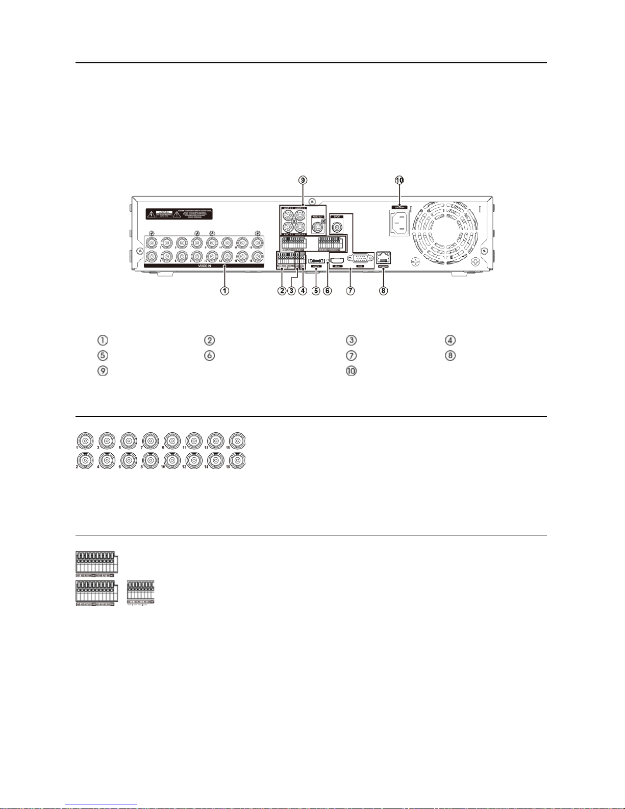
Installation
No special tools are required to install the DVR. Refer to the installation manuals for the other items that make
up part of your system.
Your DVR can be used with either NTSC or PAL equipment.
NOTE:
You cannot mix NTSC and PAL equipment. For example you cannot use a PAL camera and an
NTSC monitor.
< DVR rear panel >
Video Input
Alarm Input/Output
RS485 P ort
RS232 P ort
eSATA Port Factory Reset Switch
Video Out
Network Port
Audio In/Out
Power Cord Connector
Video Input
Connect the coaxial cables from the vid eo sources to the BNC Video In connectors.
Alarm Input/Output
AI 1 to 16 (Alarm-In): You can use external devices to signal the DVR to react to events. Me chanical or ele ctrical
switches can be wired to the AI (Alarm-In) and GND (Ground) connectors. The threshold voltage of electrical
switches for NC (Normally Closed) is above 2.4V and for NO (Normally Open) is below 0.3V , and should be
stable at least 0.5 seconds to be detected. The voltage range of alarm input is from 0V to 5V.
GND (Ground): Connect th e ground side of the Alarm i nput and/or alarm output to the GND connector.
NOTE:
All the connectors marked GND are common.
NC/NO (Relay Alarm Outputs): The DVR can activate external devices such as buzzers or lights. Connect
the device to the C (Common) and NC (Normally Cl osed ) or C (Common) and NO (Normally Open)
connectors. NC/NO is a relay output which sinks 2A@125VAC and 1A@30VDC.
Your DVR ca n recor d audio from up t o four sources. Co nnect the
audio source s to Audio In 1, Audio In 2, Audio In 3 and Audio In
4 as neede d us in g RCA jacks. Connect Audio Out to your
amplifier.
NOTE: To make connections on the Alarm Connector Strip, press and hold
the button and insert the wire in the hole below the button. After releasing the
button, tug gently on the wire to make certain it is connected. To d isco nne ct a
wire, press and hold the button above the wire and pull out the wire.
 Loading...