

Eneo TVR-2008AM4.0, TVR-2016AM4.0 User Manual

EN
User Manual
Hybrid Video Recorder
TVR-2008AM4.0
TVR-2016AM4.0
Digital Video Recorder
i
WARNING
RISK OF ELECTRIC SHOCK
DO NOT OPEN
WARNING: TO REDUCE THE RISK OF ELECTRIC SHOCK,
DO NOT REMOVE COVER (OR BACK).
NO USER-SERVICEABLE PARTS INSIDE.
REFER SERVICING TO QUALIFIED
SERVICE PERSONNEL.
The lightning flash with arr owhead symbol, w ithin an equilater al triangle, is i ntended to aler t
the user to the pre sence of un insul ated " danger ous voltag e" w ithin the product’s enclosure
that may be of sufficient magnitude to constitute a risk of electric shock.
The exclamat ion point within an equilateral triangle is intended to alert the user to the presence
of important operati ng and main tenance (s ervicin g) instr uctions in the li teratur e accompany ing
the appliance.
Symbol
Publication
Description
IEC60417, No.5032 Alternating current
COMPLIANCE NOTICE OF FCC:
THIS EQUIPMENT HAS BEEN TESTED AND FOUND TO COMPLY WITH THE LIMITS FOR A CLASS A DIGITAL
DEVICE, PURSUANT TO PART 15 OF THE FCC RULES. THESE LIMITS ARE DESIGNED TO PROVIDE
REASONABLE PROT ECTIO N AG AINST HARM FUL INTER FER ENCE WHEN THE EQUIPMENT IS OP ERATED IN
A COMMERCIAL ENVIRONMENT. THIS EQUIPMENT GENERATES, USES, AND CAN RADIATE RADIO
FREQUENCY ENERGY AND IF NOT INSTALLED AND USED IN ACCORDANCE WITH THE INSTRUCTION
MANUAL, MAY CAUSE HARMFUL INTERFERENCE TO RADIO COMMUNICATIONS. OPERATION OF THIS
EQUIPMENT IN A RESIDENTIAL AREA IS LIKELY TO CAUSE HARMFUL INTERFERENCE, IN WHICH CASE
USERS WILL BE REQUIRED TO CORRECT THE INTERFERENCE AT THEI R OW N EXPENSE .
WARNING: CHANGES OR MOD IFIC AT IONS NOT EXPR ESSL Y APPROVED BY TH E PARTY RESPO N SIBL E FOR
COMPLIANCE COULD VOID THE USER’S AUTHORITY TO OPERATE THE EQUIPMENT.
THIS CLASS OF DIGITAL APPARATUS MEETS ALL REQUIREMENTS OF THE CANADIAN INTERFERENCECAUSING EQUIPMENT REGULATIONS.
The information in this manual is believed to be accurate as of the date of publication even though explanation about
some functions may not be incorporated. We are not responsible for any problems resulting from the use thereof. The
information contained herein is subject to change without notice. Revisions or new editions to this publication may be
issued to incorporate such changes.
The software included in this product contains some Open Sources. You may obtain the complete corresponding source
code from us. See the Open Source Guide on the software CD (OpenSourceGuide\OpenSourceGuide.pdf) or as a printed
document included along with the User's Manual.
User’s Manual
ii
Important Safeguards
1. Read Instructions
All the safety and operating instructions should be read before the
appliance is operated.
2. R
etain Instructions
The safety and operating inst ructi ons should be retain ed for futu re
reference.
3. C
leaning
Unplug this equipment from the wall outlet before cleaning it. Do
not use liquid aerosol cleaners. Use a damp soft cloth for cleaning.
4. At
tachments
Never add any attachments and/or equipment without the approval
of the manufacturer as such additions may result in the risk of fire,
electric shock or other personal injury.
5. W
ater and/or Moisture
Do not use this equipment near water or in contact with water.
6. Placement and Accessories
Do not place t his equipment on an unstable cart,
stand or table. The equipment may fall, causing
serious injury to a child or adult, and serious
damage to the equipment .
This equipment and cart c ombination should be
moved with care. Quick stops, excessive force,
and uneven surfaces may cause the equipment and cart
combination to overturn.
Do not place this equipment on a closed space. Sufficient amount of
ventilation air is necessary to avoid increase of ambient temperature
which can cause improper operation or the risk of fire.
7. P
ower Sources
This equipment shoul d be o perate d o nly from the ty pe o f powe r sour ce
indicated on the mark ing label. I f you a re not sure of the type of pow er,
please consult your equipment dealer or local power company.
You may want to install a UPS (Uninterruptible Power Supply)
system for safe operation in order to prevent damage caused by an
unexpected power st oppage. Any questions concerning UPS,
consult your UPS retailer.
This equipment should be remain readily operable.
8. P
ower Cords
Operator or installer must remove power and TNT connections before
handling the equipment.
9. L
ightning
For added prot ect i on for thi s e quip m ent du rin g a light ni n g storm , or
when it is l eft u natten ded a nd u nused f or lo ng perio ds o f tim e, un plug
it from the wa ll outl et and disc onnect the an tenna or c able sy stem. This
will prevent damage to the equipment due to lightning and
power-line surges.
10. Overloading
Do not overload wall outlets and extension cords as thi s can resu lt
in the risk of fire or elect ric shock.
11. O
bjects and Liquids
Never push objects of any kind through openings of this equipment
as they may touch d ange rous volt age p oints or sh ort out parts that
could result in a fire or electric shock. Nev e r spil l liquid of any kind
on the equipment.
12. Servicing
Do not attempt to service this equipment yourself. Refer al l serv ic ing
to qualified service personnel.
13. D
amage requ iring Service
Unplug this equipment from the wall outlet and refer s ervicing t
o
q
ualified service personnel under the following conditions:
A. When the po w e r -supply cord or the plug has been damaged.
B. If liquid is spilled, or objects have fallen in to the equipment.
C. If the equipment has been exposed to rain or water.
D. If the equipment does not operate normally by follow ing the operating
instructions, adjus t only those controls that are covered by the
operating in str uctio ns a s an impr ope r ad justme nt o f othe r co ntrol s
may result in damage and will often require extensive work by a
qualified technicia n to re store the e quipme nt to its no rmal operatio n.
E. If the equipment has been dropped, or the cabinet damaged.
F. When the equipment e xhibi ts a disti nct cha nge in perf orma nce –
this indicates a need for service.
14. R
eplacement Parts
When replacement parts are required, be sure the service technician
has used replacement parts specified by the manufacturer or that have
the same charac teristics a s the o riginal part. Unauthorized subst itutions
may result in fire, electric shock or other hazards.
15. Safety Chec k
Upon comple tio n of any serv ice o r r epa ir s to th is e q ui pm ent, ask the
service technician to perform safety checks to determine that the
equipment is in proper operating condition.
16. F
ield Inst allation
This installation should be made by a qualified service per son and
should conform to all loc al codes.
17. C
orrect Bat teries
Warning: Risk of explosion if battery is replaced by an incorrect type.
Replace only with the same or equivalent type.
Dispose of used batter ies according to the instructions.
The battery shall not be exposed to excessive h eat such as sun shine, fire
or the like.
18. T
mra
A manufacturer’s maximum recommended ambient temperature (Tmra)
for the equipm ent m ust be specif ied so tha t the cu stomer and in stall er
may determine a suitable maximum operating environment for the
equipment.
WEEE (Waste Electrical & Electronic Equipment)
Correct Disposal of This Product
(Applicable in the European Union and other European countries with separate collection systems)
This marking shown on the product or its literature, indicates that it should not be disposed with other household wastes at
the end of its working life. To prevent possible harm to the environment or human health from uncontrolled waste disposal,
please separate this from other types of wastes and recycle it responsibly to promote the sustainable re use of material
resources.
Household users should contact either the retail er where they purchased this prod uct, or their l ocal government office, for
details of where and how they can take this item for environmentally safe recycling.
Business users should contact their supplier and check the terms a nd conditions of the purchase contract. This product
should not be mixed with other commercial wastes for disposal.

Digital Video Recorder
iii
Table of Contents
Chapter 1 — Introduction................................................................................................................... 1
Feature .......................................................................................................................................... 1
Technical Overview ....................................................................................................................... 1
Chapter 2 — Installation .................................................................................................................... 3
Package Contents ......................................................................................................................... 3
Required Installation Tools ............................................................................................................ 3
Video Input ............................................................................................................................... 3
Alarm Input/Output ................................................................................................................... 4
RS485 Port ............................................................................................................................... 4
RS232 Port ............................................................................................................................... 4
eSATA Port ............................................................................................................................... 5
Factory Reset Switch ................................................................................................................ 5
Video Out .................................................................................................................................. 5
Network Port ............................................................................................................................. 5
Audio In/Out .............................................................................................................................. 6
Power Cord Connector ............................................................................................................. 6
Chapter 3 — Configuration ................................................................................................................ 7
Front Panel Controls ..................................................................................................................... 7
Camera Buttons ........................................................................................................................ 8
DISPLAY/SPOT Button ............................................................................................................ 8
GROUP/SEQUENCE Button .................................................................................................... 8
MENU/CAMEO Button ............................................................................................................. 8
Power LED ............................................................................................................................... 9
HDD LED .................................................................................................................................. 9
Alarm Out LED ......................................................................................................................... 9
Network LED ............................................................................................................................ 9
Clip Copy LED .......................................................................................................................... 9
USB Port ................................................................................................................................... 9
Arrow Buttons ......................................................................................................................... 10
PLAY/PAUSE Button .............................................................................................................. 10
PANIC Button ......................................................................................................................... 10
PLAYBACK Button ................................................................................................................. 10
ALARM Button ........................................................................................................................ 10
CLIP COPY Button ................................................................................................................. 10
ZOOM/PTZ Button .................................................................................................................. 10
ID Button on Remote Control ................................................................................................. 11
Bookmark Button on Remote Control ..................................................................................... 11
Turning on the Power .................................................................................................................. 11
Initial Unit Setup .......................................................................................................................... 11
Setup Screen .............................................................................................................................. 12
System Setup .............................................................................................................................. 13
General ................................................................................................................................... 13
Date/Time ............................................................................................................................... 21
User ........................................................................................................................................ 22
Storage ................................................................................................................................... 24
System Event ......................................................................................................................... 25
Recording Setup ......................................................................................................................... 26
General ................................................................................................................................... 26

User’s Manual
iv

Digital Video Recorder
v
Schedule ................................................................................................................................. 27
Pre-Event ................................................................................................................................ 30
Event Setup ................................................................................................................................. 31
Motion ..................................................................................................................................... 31
Alarm-In .................................................................................................................................. 32
Video Loss .............................................................................................................................. 33
Video Blind ............................................................................................................................. 34
Text-In .................................................................................................................................... 35
Camera Setup ............................................................................................................................. 37
General ................................................................................................................................... 37
PTZ ......................................................................................................................................... 38
Device Setup ............................................................................................................................... 39
Audio ...................................................................................................................................... 39
Alarm-Out ............................................................................................................................... 39
Remote Control ...................................................................................................................... 40
Network Setup ............................................................................................................................. 41
General ................................................................................................................................... 41
LAN ......................................................................................................................................... 42
FEN ........................................................................................................................................ 44
RTSP ...................................................................................................................................... 45
WebGuard .............................................................................................................................. 46
VNC ........................................................................................................................................ 46
NetFS ..................................................................................................................................... 47
Notification Setup ........................................................................................................................ 49
Callback .................................................................................................................................. 49
Mail ......................................................................................................................................... 49
SNS ........................................................................................................................................ 51
FTP ......................................................................................................................................... 52
Schedule ................................................................................................................................. 53
Display Setup .............................................................................................................................. 54
OSD ........................................................................................................................................ 54
Main Monitor ........................................................................................................................... 55
Spot Monitor ........................................................................................................................... 56
Chapter 4 — Operation.................................................................................................................... 57
Turning on the Power .................................................................................................................. 57
Live Monitoring ............................................................................................................................ 57
Live Monitoring Menu ............................................................................................................. 58
Active Cameo Mode ............................................................................................................... 60
Zoom Mode ............................................................................................................................ 60
PTZ Mode ............................................................................................................................... 60
Event Monitoring ..................................................................................................................... 62
Covert Camera ....................................................................................................................... 62
Spot Monitoring ...................................................................................................................... 62
Status Monitoring .................................................................................................................... 63
Recording Video .......................................................................................................................... 64
Panic Recording ..................................................................................................................... 65
Recording Audio .......................................................................................................................... 65
Playing Recorded Video .............................................................................................................. 65
Searching Video .......................................................................................................................... 66
Search Menu .......................................................................................................................... 67
Event Log Search ................................................................................................................... 69
Record Table Search .............................................................................................................. 71
Motion Search ........................................................................................................................ 72

User’s Manual
vi
Text-In Search ........................................................................................................................ 74
Bookmarks .............................................................................................................................. 75
Clip-Copy ................................................................................................................................ 76
Print ........................................................................................................................................ 78
Appendix .......................................................................................................................................... 79
USB Hard Disk Drive Preparation ............................................................................................... 79
Text-In Search Examples ............................................................................................................ 79
Search Example I ................................................................................................................... 79
Search Example II .................................................................................................................. 80
WebGuard ................................................................................................................................... 81
Web Monitoring Mode ............................................................................................................ 82
Web Search Mode .................................................................................................................. 84
Time Overlap ............................................................................................................................... 86
Error Code Notices ...................................................................................................................... 86
System Log Notices .................................................................................................................... 87
Map of Screens ........................................................................................................................... 88
Troubleshooting .......................................................................................................................... 89
Specifications .............................................................................................................................. 89
List of Illustrations
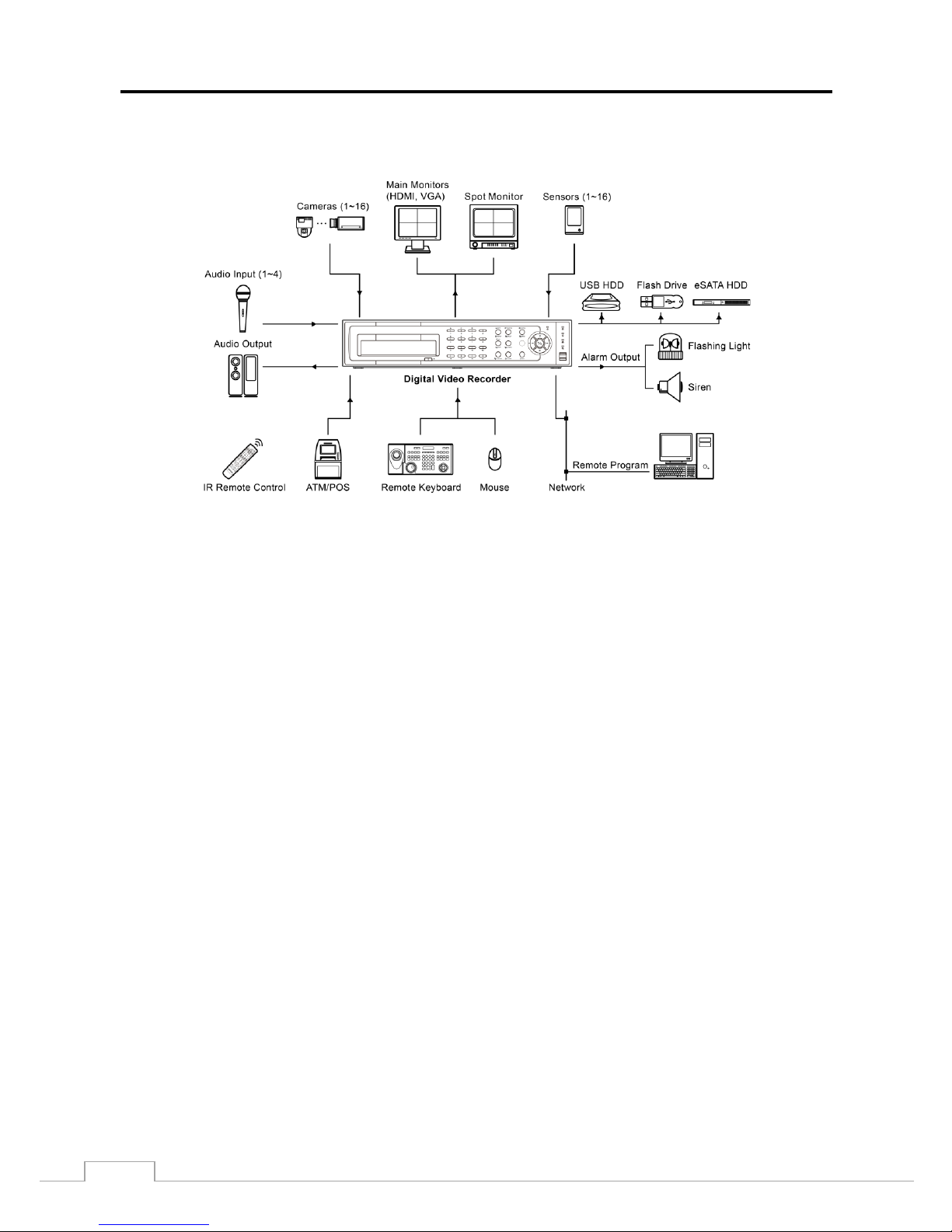
Figure 1: Typical DVR installation. ............................................................................................................ 2
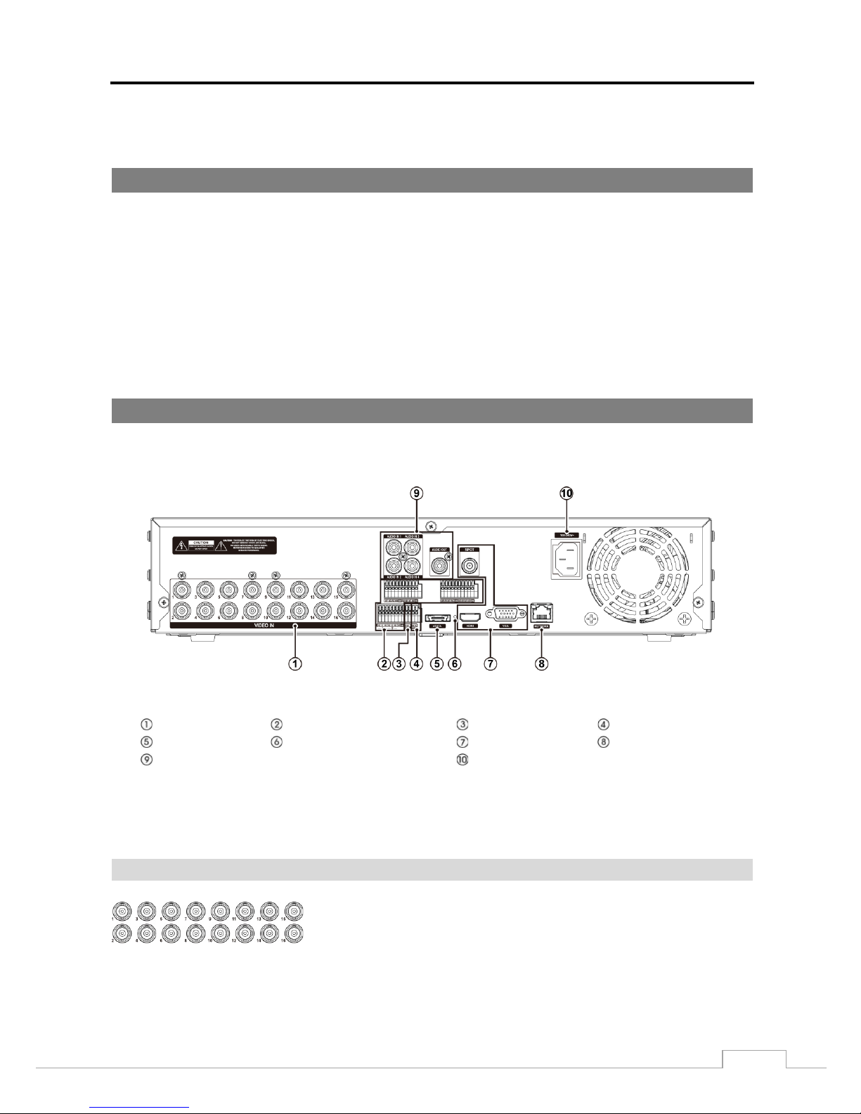
Figure 2: DVR rear panel. ......................................................................................................................... 3
Figure 3: DVR front panel. ........................................................................................................................ 7
Figure 4: Infrared remote control. .............................................................................................................. 8
Figure 5: Login screen. ............................................................................................................................11
Figure 6: Logout screen. ..........................................................................................................................12
Figure 7: Setup screen. ............................................................................................................................12
Figure 8: System – General setup screen. ...............................................................................................13
Figure 9: System – Date/Time setup screen. ...........................................................................................21
Figure 10: System – User setup screen. ..................................................................................................22
Figure 11: System – Storage setup screen. .............................................................................................24
Figure 12: System – System Event setup screen. ...................................................................................25
Figure 13: Record – General setup screen. .............................................................................................26
Figure 14: Record – Schedule setup screen. ...........................................................................................27
Figure 15: Schedule – Settings (Advanced Mode) setup screen. ............................................................28
Figure 16: Record – Pre-Event setup screen. ..........................................................................................30
Figure 17: Event – Motion setup screen...................................................................................................31
Figure 18: Event – Alarm-In setup screen. ...............................................................................................32
Figure 19: Event – Video Loss setup screen. ...........................................................................................33
Figure 20: Event – Video Blind setup screen. ..........................................................................................34
Figure 21: Event – Text-In setup screen. .................................................................................................35
Figure 22: Camera – General setup screen. ............................................................................................37
Figure 23: Camera – PTZ setup screen. ..................................................................................................38
Figure 24: Device – Audio setup screen. .................................................................................................39
Figure 25: Device – Alarm-Out setup screen. ..........................................................................................39
Figure 26: Device – Remote Control setup screen. .................................................................................40
Figure 27: Network – General setup screen. ............................................................................................41
Figure 28: Network – LAN setup screen. .................................................................................................42
Figure 29: Network – FEN setup screen. .................................................................................................44

Digital Video Recorder
vii
Figure 30: Network – RTSP setup screen. ...............................................................................................45
Figure 31: Network – WebGuard setup screen. .......................................................................................46
Figure 32: Network – VNC setup screen. .................................................................................................46
Figure 33: Network – NetFS. ....................................................................................................................48
Figure 34: Notification – Callback setup screen. ......................................................................................49
Figure 35: Notification – Mail setup screen. .............................................................................................49
Figure 36: Notification – SNS setup screen. ............................................................................................51
Figure 37: Notification – FTP setup screen. .............................................................................................52
Figure 38: Notification – Schedule setup screen. .....................................................................................53
Figure 39: Display – OSD setup screen. ..................................................................................................54
Figure 40: Display – Main Monitor setup screen. .....................................................................................55
Figure 38 : Display – Spot Monitor setup screen. ...................................................................................56
Figure 41: Live Monitoring menu. .............................................................................................................57
Figure 42: PTZ Select Camera menu.......................................................................................................61
Figure 43: PTZ Preset menu. ...................................................................................................................61
Figure 44: Event Status – Event Status screen. .......................................................................................63
Figure 45: Event Status – Storage screen. ..............................................................................................64
Figure 46: Select Playback Camera menu. ..............................................................................................65
Figure 47: Search menu...........................................................................................................................66
Figure 48: Event Log Search screen. .......................................................................................................69
Figure 49: Record Table Search screen. .................................................................................................71
Figure 50: Motion Search screen. ............................................................................................................72
Figure 51: Text-In Search screen. ............................................................................................................74
Figure 52: Bookmarks screen. .................................................................................................................75
Figure 53: Clip-Copy screen. ...................................................................................................................76
Figure 54: Print screen. ............................................................................................................................78


Digital Video Recorder
1
Chapter 1 — Introduction
Feature
Your color digita l v i de o rec or de r (D VR) pr ov i de s rec ordi ng c a pa bi li ties f or eight or 16 cam e ra i nputs . I t pr ov i de s
exceptional picture quality in both live and playback modes, and offers the following features:
Live Monitoring for Each Channel
Compatible with Color (NTSC or PAL) and B&W (CCIR and EIA-170) Video Sources
Auto Detection for HD-TVI Input
Auto Detection for NTSC and PAL
H.264 Codec
Multiple Monitor Connectors: 1 HDMI, 1 VGA, 1 SPOT
UTC for Camera Menu Control via Coax Cable
Mul tiple Search Engines (Date/Time, Calendar, Record Table, Event)
Real-time Recording (480 Images per Second with High (HD) Resolution)
Continuous Recording in Disk Overwrite Mode
Video Recording vi a eSATA Interface
2 USB 2.0 Ports
Continues Recording while Transmitting to Remote Site and duri ng Playback
User-frien dly Graphical User Interface (GUI) Menu System
Multiple Recording Modes (Time-lapse, Pre-event, Alarm, Motion and Panic)
Two-way Audio Communication
4-Channel Audio Recording and 1-Channel Audio Playback
Text Input for ATM and POS
Alarm Connections Include: Input, Output
Built-in Alarm Buzzer
Live or Reco r ded Video Access via Ethernet
Time Synchronization using industry standard protocol
IR Remote Control
Self-diagnostics with automatic notification including hard disk drive S.M.A.R.T. protocol
Technical Overview
In addition to replac ing both a time-l apse VCR a nd a multiplexe r in a security i nstallati on, your DVR has many features
that make it much more powerful and easier to use than even the most advanced VCR.
The DVR converts analog NTSC or PAL vide o to digit al ima ges a nd records t hem on a hard dis k driv e. Us ing a har d
disk drive allows you to acc ess recorde d vi deo a lmost ins tantane ously ; the re is no nee d to rew ind tape . The technology
also allows you to view recorded video while the DVR continues recording video.
Digitally recor ded vide o has se veral adv antage s over a nalog vi deo recorde d on tape . Ther e is no need to adjust t rack ing.
You can freeze frames, fast forward, fast reverse, slow forward and slow reverse without image streaking or tearing.
Digital video can b e in dexed by time or events, and you can instantly view video after selecting the t ime or event.
Your DVR can be se t up for ev ent or ti me-la pse recordi ng. You ca n define times to r ecord, a nd the sc hedule can change
for different days of the week and user defined holidays.
The DVR can be se t up to a l e rt y ou w he n the ha r d dis k drive is full , or i t c a n be s e t to r e c ord over the oldest video once
the disk is full.
Your DVR uses a proprietary encryption scheme making it nearly impossible to alter video.
User’s Manual
2
You can view v ideo a nd co ntrol your D VR re m otel y by c onnec ting via Ethe rnet . There is an eSATA port that can be
used to record video to external hard disk drives, and there are two USB ports that can be used to upgrade the system
or copy video clips to external hard disk and flash drives.
Figure 1: Typical DVR installation.
NOTE:
This manual covers the 8- and 16-channel digital video recorders. The DVRs are identical ex cep t f or t he number of
cameras and al a rms that can be connected and the number of cameras that can be displayed. For simplicity, the
illustrations and descriptions in this manual refer to the 16-camera model.
Digital Video Recorder
3
Chapter 2 — Installation
Package Contents
The package contains the following:
Digital Vid eo Recorder
Power Cord
Quick User Guide
Software CD (User’s Manual included)
Rack-mount Kit
As sembly S crews for Adding Hard Disk Drives
SATA Cabl es
Infrared Remote Control
Required Installation Tools
No special tools are required to install the DVR. Refer to t he ins t a llation manuals for the othe r i tem s that m ak e up pa r t
of your system.
Figure 2: DVR rear panel.
Video Input
Alarm Input/O utput
RS485 Port
RS232 Port
eSATA Port
Factory Reset Sw itch
Video Out
Network Port
Audio In/Out
Power Cord Connect or
Your DVR can be used with either NTSC or PAL equipment.
NOTE:
You cannot mix NTSC and PAL equipment. For example you cannot use a PAL camera and an NTSC
monitor.
Video Input
Connect the coaxial cables from the video sources to the BNC Video In
connectors.
User’s Manual
4
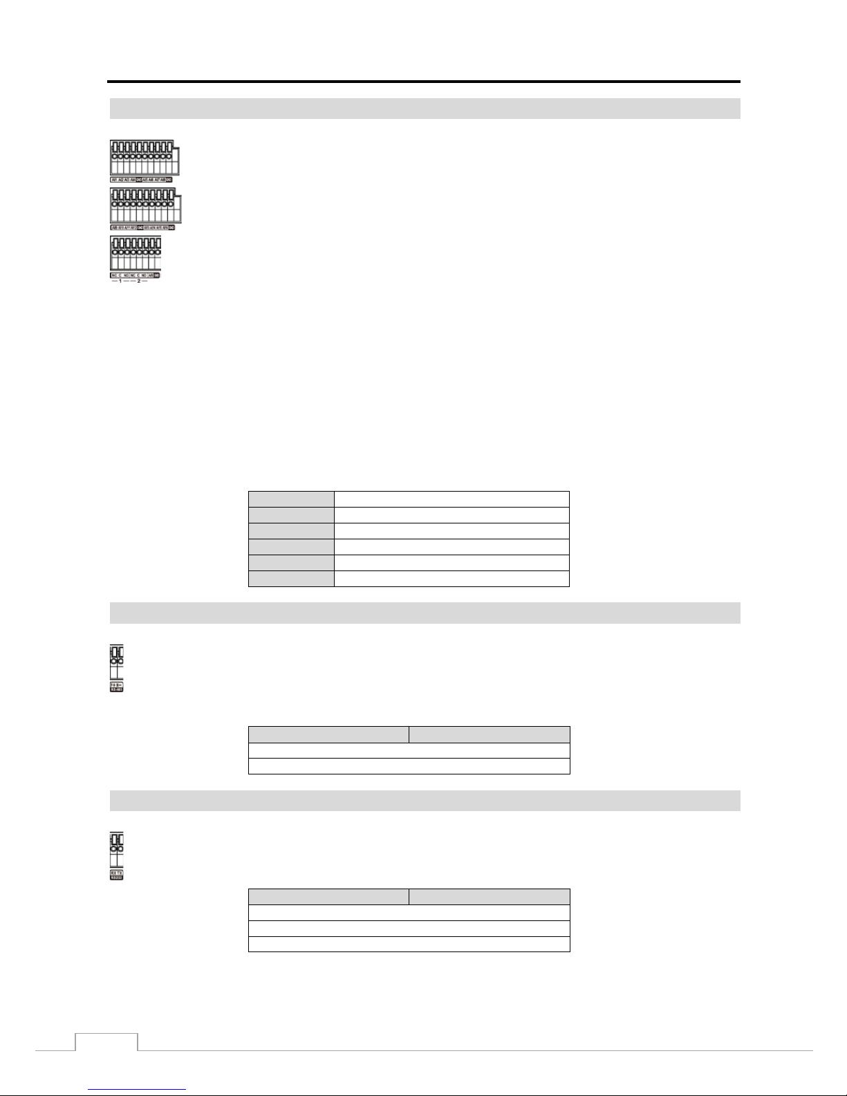
Alarm Input/Output
GND (Ground): Connect the ground side of the Alarm input and/or alarm output to the GND connector.
NOTE:
All the connectors marked GND are common.
NC/NO (Relay Alarm Outputs): The DVR can activate external devices such as buzzers or lights. Connect the
device to the C (Common) and NC (Normally Closed) or C (Common) and NO (Normally Open) connectors.
NC/NO is a relay output which sinks 2A@125VAC and 1A@30VDC. See Chapter 3 ─ Configuration for
configuring alarm output.
ARI (Alarm Reset In): An external signal to the Alarm Reset In can be used to reset both the Alarm Out signal and
the DVR’s internal buzzer. Mechanical or electrical switches can be wired to the ARI (Alarm Reset In) and GND (Ground)
connectors. T he thres hold volta ge is be low 0.3V an d should be stabl e at lea st 0.5 sec onds to be dete cted. Connect the
wires to the ARI and GND connectors.
Connector Pin Outs:
AI (1 to 16)
Alarm Inputs 1 to 16
GND
Chassis Ground
NC
Relay Alarm O ut (Normally Closed)
C
Relay Common
NO
Relay Alarm Out (Normally Open)
ARI
Alarm Reset In
RS485 Port
Connector Pin Outs:
Master Unit
Slave Unit
+
→ To →
TX+/RX+ –
→ To →
TX–/RX–
RS232 Port
Connector Pin Outs:
Master Unit
Slave Unit
RX
→ To →
TXD
TX
→ To →
RXD GND
→ To →
GND
NOTE: To make connections on the Alarm Connector Strip, press and hold the button and
insert the wire i n the hole bel o w t he b ut t on. After releasing the button, tug gently on the wire to
make certain it is connected. To disconnect a wire, press and hold t he butt on abov e t he wire
and pull out the wire.
AI 1 to 16 (Alarm-In): You can use external devices to signal the DVR to react to events .
Mechanical or electrical switches can be wired to the AI (Alarm-In) and GND (Ground) connectors .
The threshold volt a ge of electrical switches for NC (Normally Closed) is above 2.4V and for NO
(Normally Open) is below 0.3V, and should be stable at least 0.5 seconds to be detected. The
voltage range of alarm input is from 0V to 5V. See Chapter 3 ─ Configuration for configuring
alarm input.
The DVR can be co ntrol le d re m otely by an e xt erna l de vic e or contr ol s y st em , suc h as a cont rol k ey boa rd,
using RS485 half-duplex serial com m uni ca tions signals. The RS485 connector c a n a ls o be us e d t o c ontr ol
PTZ (pan, tilt, zoom) ca mer as . Connect RX+/TX+ and RX–/TX– of the control system to the + and –
(respectively) of th e D VR. See Chapter 3 ─ Configuration and the PTZ camera or remote controller
manufacture’s manual for configuring the RS485 connection.
An RS232 port is pr ovided to connect remote control devices such as a control keyboard. PTZ cameras or
text-in device s ca n a lso be c onne cte d t o the RS2 32 p ort. See Chapter 3 ─ Configuration and the PTZ camera,
text-in device or remote controller manufacturer’s manu al for configuring the RS232 connection.
Digital Video Recorder
5
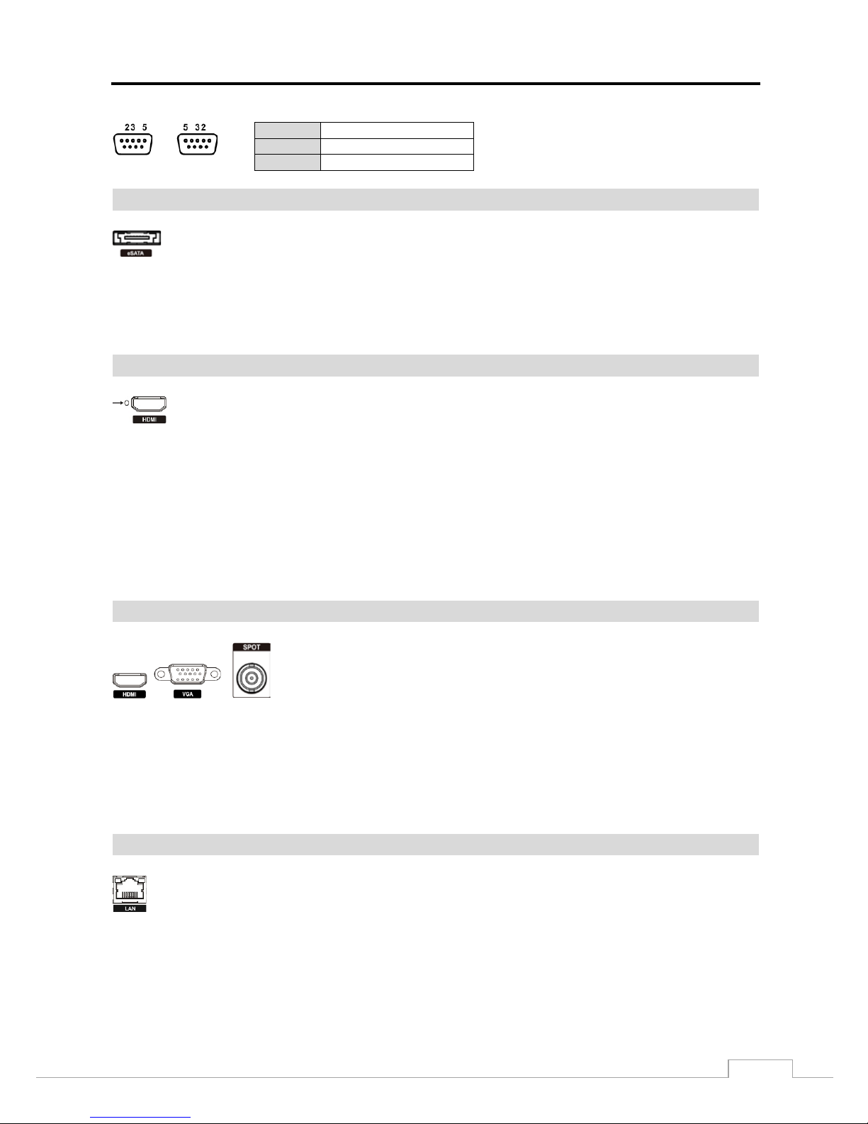
NOTE:
Refer to the following for pin-out details for the 9-pin connector of the slave unit.
Male
Female
Pin 2
RXD (Receive Dat a)
Pin 3
TXD (Transmit Data)
Pin 5
GND (Ground)
eSATA Port
An eSATA port is provi ded to connect external s torage devi ces for recording or archiving vi deo. Connect
the external eSATA hard di sk drive (RAID) cable to the eSATA port.
CAUTION:
Do NOT connect or disconnect eSATA devices while the DVR power is on. The DVR must
be powered down to connect or disconn ect eSA TA devices. Power up eSA TA devices
so they are ready for operation before powering up the DVR. Power down eSATA devices
after powering down the DVR and then disconnect eSATA devices.
Factory Reset Switch
The DVR has a Factory Reset switch to the left of the HDMI connector on the r ear panel. This
switch wil l onl y be used on the r a r e oc c a s i ons that you want to return all the settings to the orig i nal
factory settings.
CAUTION:
When using the Factory Reset, you will lose any settings you have saved.
To reset the unit, you will need a straightened paperclip:
1. Turn the DVR off.
2. Turn it on again.
3. Poke the straightened paperclip into the unlabeled hol e to the left of the HDMI connector.
4. Hold the reset switch until the DVR’s internal buzzer sounds twice.
5. Release the reset switch. All of the DVR’s settings are now at the original settings it had when it left the factory.
Video Out
An HDMI (High-Definition Multimedia Interface) connector is provided so that
you can use an HDMI monitor as your main monitor.
A VGA connector is provided so that you can use a standard, multi-sync computer
monitor as y our m ain m onitor. Us e t he cabl e suppl ied w ith y our moni tor to c onne ct
it to the DVR.
Connect the spot monitor to the SPOT connector as needed.
NOTE:
Connect the monitor before t he DVR b oots so that v ideo can be display ed on t he monitor with the resolution
you have set during system setup. If you want to use both the HDMI and VGA Monitor connectors, one
of the monitors should be connected before the D VR boot s, and the othe r monitor should be connected
after the DVR boots.
Network Port
CAUTION:
The network connector is not designed to be connected directly with cable or wire
intended for outdoor use.
The DVR can be net worke d using the 10Mb/ 100Mb/1Gb Ethernet connector. Connect a Cat5e cable with
an RJ-45 jack to the DVR c onnector . The D VR can be ne twork ed with a c ompute r for rem ote monitor ing,
searching, configuration and software upgrades. See Chapter 3 ─ Configuration for configuring the
Ethernet connections.
User’s Manual
6
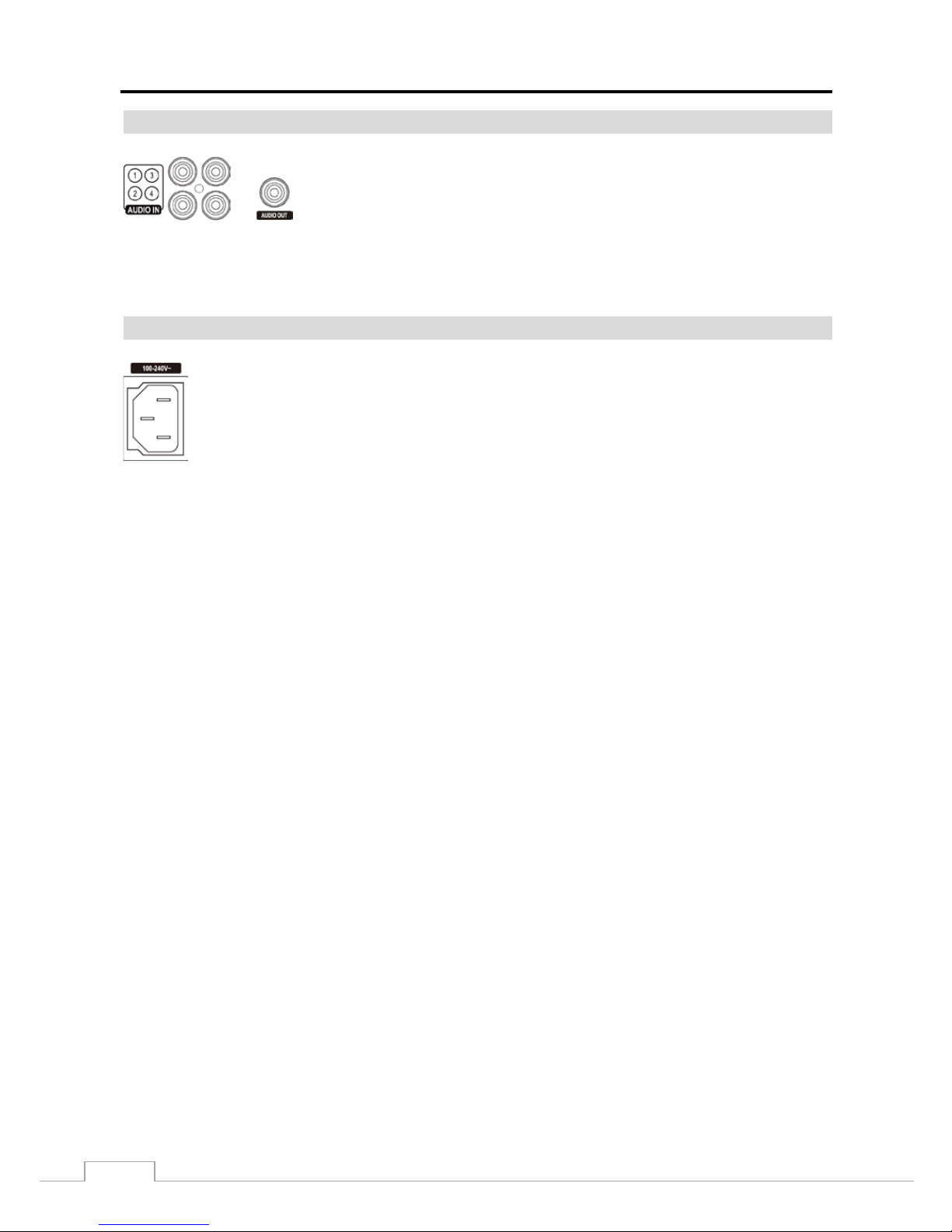
Audio In/Out
NOTE:
It is the user’s responsibility to determine if local laws and regulations permit recording audio.
The DVR does not have a mplifie d audi o out put, so you will need a spea ker with an am plifier. The DVR
does not have a pre-amplifier for audio input, so the audio input should be from an amplified source,
not directly from a microphone.
Power Cord Connector
WARNING:
ROUTE POWER CORDS SO THAT THEY ARE NOT A TRIPPING HAZARD. MAKE
CERTAIN THE POWER CORD WILL NOT BE PINCHED OR ABRADED BY FURNITURE.
DO NOT INSTALL POWER CORDS UNDER RUGS OR CARPET.
THE POWER CORD HAS A GROUNDING PIN. IF YOUR POWER OUTLET DOES NOT
HAVE A GROUNDING PIN RECEPTACLE, DO NOT MODIFY THE PLUG. DO NOT
OVERLOAD THE CIRCUIT BY PLUGGING TOO MANY DEVI CES IN TO ONE CIRCUIT.
Your DVR is now ready to operate. Refer to Chapter 3 ─ Configuration and Chapter 4 ─ Operation.
Your DVR can record audio from up to four sources. Connect the audio sources to
Audio In 1, Audio In 2, Audio In 3 and Audio In 4 as needed using RCA jacks.
Connect Audio Out to your amplifier.
Connect the AC power cord to the DVR and then to a wall outlet.
Digital Video Recorder
7
Chapter 3 — Configuration
NOTE:
Your DVR should be completely installed before proceeding. Refer to Chapter 2 — Installation.
Front Panel Controls
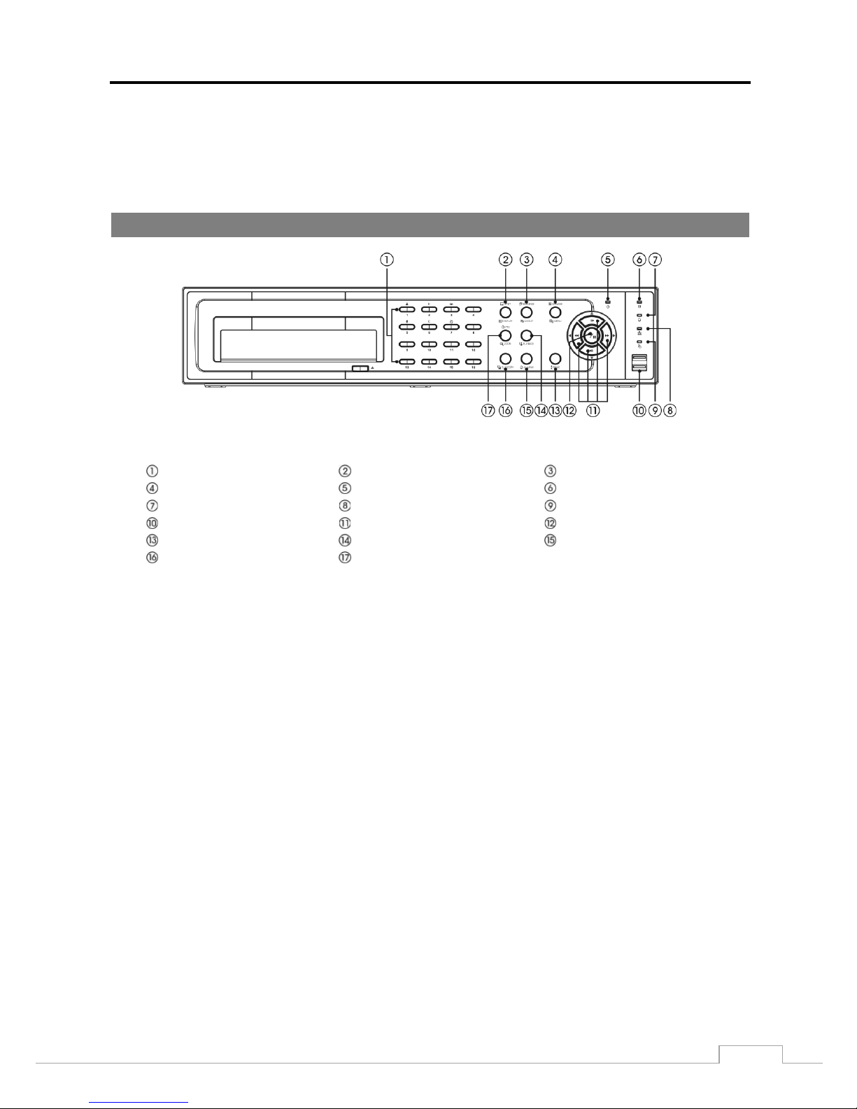
Figure 3: DVR front panel.
Camera Buttons
Display/SPOT Button
Group/Sequence Button
Menu/Cameo Button
Power LED
HDD LED
Alarm Out LED
Network LED
Clip Copy LED
USB Connector
Arrow Buttons
Play/Pause Button
Panic Button
Playback Mode Button
Alarm Button
Clip Copy Button
Zoom/PTZ Button
The front panel look s a nd ope r a tes much like a VCR combi ne d w ith a multiplexer. Many of the buttons have m ul ti ple
functions. T he but tons on the inf r are d re m ote c ontrol , w hi le la id out dif f ere ntly , per f orm t he s am e f uncti ons as thos e
on the front panel. The following de s c r ibe s e a c h but ton and control. Tak e a f ew minutes to re v i ew the descript ions.
You will use these to initially set up your DVR and for daily operations.
NOTE:
The infrared sensor on the DVR is just to the right of the arrow buttons. Make certain that n othi ng b locks
the sensor, or the remote control will not function properly.
When you use wireless communication devices (such as Wi-Fi or Bluetooth) near the DVR , the re mot e
control might not function properly.
You can also use a USB mouse (not supplied) to navigate through the screens and menus much like
you would on a computer .
User’s Manual
8
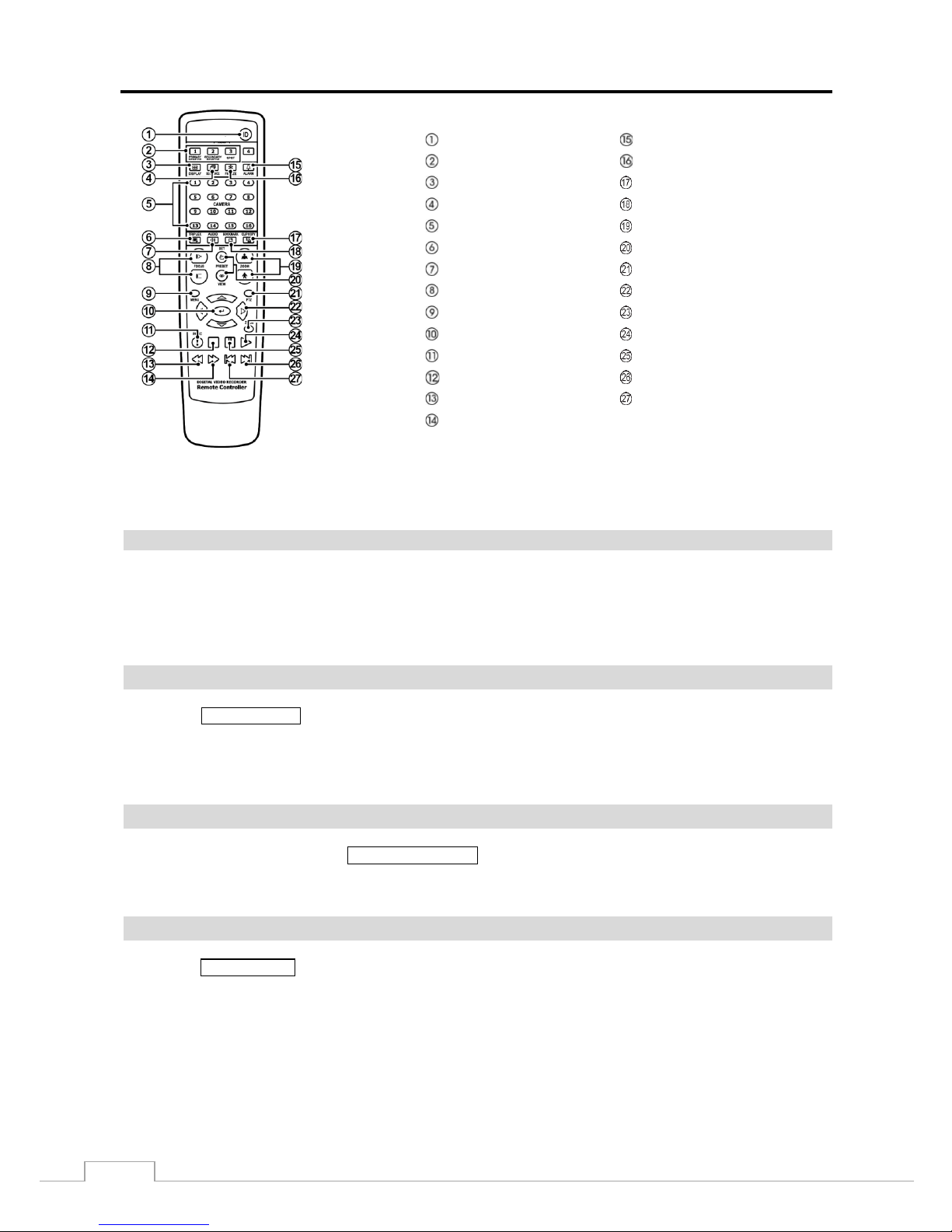
ID Button
Alarm Button
Monitor Buttons Freeze Button
Display Button
Clip Copy Button
Sequence Button
Bookmark Button
Camera Buttons
Zoom In/Out Button
Triplex Button Preset Set/View Button
Audio Buttons PTZ Mode Button
Focus Near/Far Button
Arrow Buttons
Menu Button
Zoom Mode Button
Enter Button Play Button
Panic Button Pause Button
Stop Button
Next Button
RW Button
Previous Button
FF Button
Figure 4: Infrared remote control.
NOTE:
For simplicity, the button descriptions in this manual refer to the front panel buttons .
Camera Buttons
Pressing the individual camera buttons will cause the selected camera to display full screen. Buttons are also used to
enter passwords.
In the PTZ m ode, press ing t he but ton 1 zoom s in t he s cree n and t he but ton 2 zoom s out the scre en, pre ss ing the button
3 focuses near and button 4 focuses far, and pressing the button 5 moves to the preset and button 6 saves the preset.
DISPLAY/SPOT Button
Pressing the DISPLAY/SPOT button toggles between different display formats. The available formats are: PIP, 2x2,
1+5, 1+7, 3x3 and 4x4 (2x2, 1+5, 1+7, 3x3 and 4x4 on a Spot Monitor).
Pressing and hol ding t he b utt on for three sec onds or longer allows y ou to s e le c t whi c h c am e ras w il l dis pl ay on the Spot
monitor.
GROUP/SEQUENCE Button
When in the live mode, pressing the GROUP/SEQUENCE button changes the screen from the current camera group
to the next c ame ra group, a nd t he scr een dis play s the pa ge num ber. Pres sing a nd hol ding t he butt on fo r thre e sec onds
or longer displays live channels sequentially.
MENU/CAMEO Button
Pressing the MENU/CAMEO button ente rs the Setup scre en. You w ill need to e nter the authori zed user and passw ord
to access S etup. Pressi ng the but ton also c loses the current m enu or se tup dialog box. In the Pla yback mode, pressing
the button displays the Search menu.

Digital Video Recorder
9
Pressing and hol di ng t he b ut ton for three s e conds or longer e nt e rs t he c ameo mode. The y e l low outline surrou nding
the video indicates the active cameo, and pre ss ing the a rr ow b utt ons m ove s the active cameo. Pressing the desired camera
button in the active cameo edits the cameo and displays the video of selected camera. Pressing the (Play/Pause) button
exits the Active Cameo mode. Selecting Exit Group Edit in the cameo menu displayed when pres sing the
MENU/CAMEO
button also exits the Active Cameo mode.
NOTE:
A cameo is defined as any cell within multi-screen display. The cameo mode allows you to change
the screen layout by editing the cameo.
Power LED
The Power LED is lit when the unit is On.
HDD LED
The HDD LED flickers when the DVR is recording or searching video on the hard disk drive.
Alarm Out LED
The Alarm Out LED is lit when alarm output or internal buzzer is activated.
Network LED
The Network LED is lit when the unit is connected to a network via Ethernet.
Clip Copy LED
The Clip Copy LED is lit when the DVR is clip-copying.
USB Port
Two USB ports on the front pane l are provided to c onne ct e xt erna l ha rd dis k or f l ash dr iv es f or vide o cl ip copying or
system upgrade s. Position external drives close enough to t he DVR so tha t you ca n make the cable conne ctions , usually
less than 6 feet. Use the USB cable provided with the hard disk drive to connect it to the DVR.
A USB mouse (not supplied) can be connected to one of the ports. You can use the mouse to navigate through the
screens and menus much like you would on a computer.
A PostScript™ USB printer (not supplie d) can be connecte d to one o f the por ts. You c an print selected images resulting
from a search. Refer to Chapter 4 — Operation, Searching Video.
A USB to Serial c onver ter can be conne cte d to the USB por t. M ultipl e t ex t-in devices can be used with a USB to Serial
converter.
User’s Manual
10
Arrow Buttons
These buttons a r e us e d to na v i g a t e throug h menus and GU I. Y ou c a n a ls o us e t he m to change numbers by highl ighting
a number in the menu and using the Up and Down arrow buttons to increase or decrease the number’s value.
These buttons are als o us ed to c on tr ol Pan and Ti lt w he n in t he PTZ m ode. W he n in the PI P dis pla y form at , pre ssi ng
the Up and Down arrow buttons m oves the posit ion of the small screen counter-clockwise and clockwise, and pressi ng
the Left and Right buttons changes the PIP s cr een size.
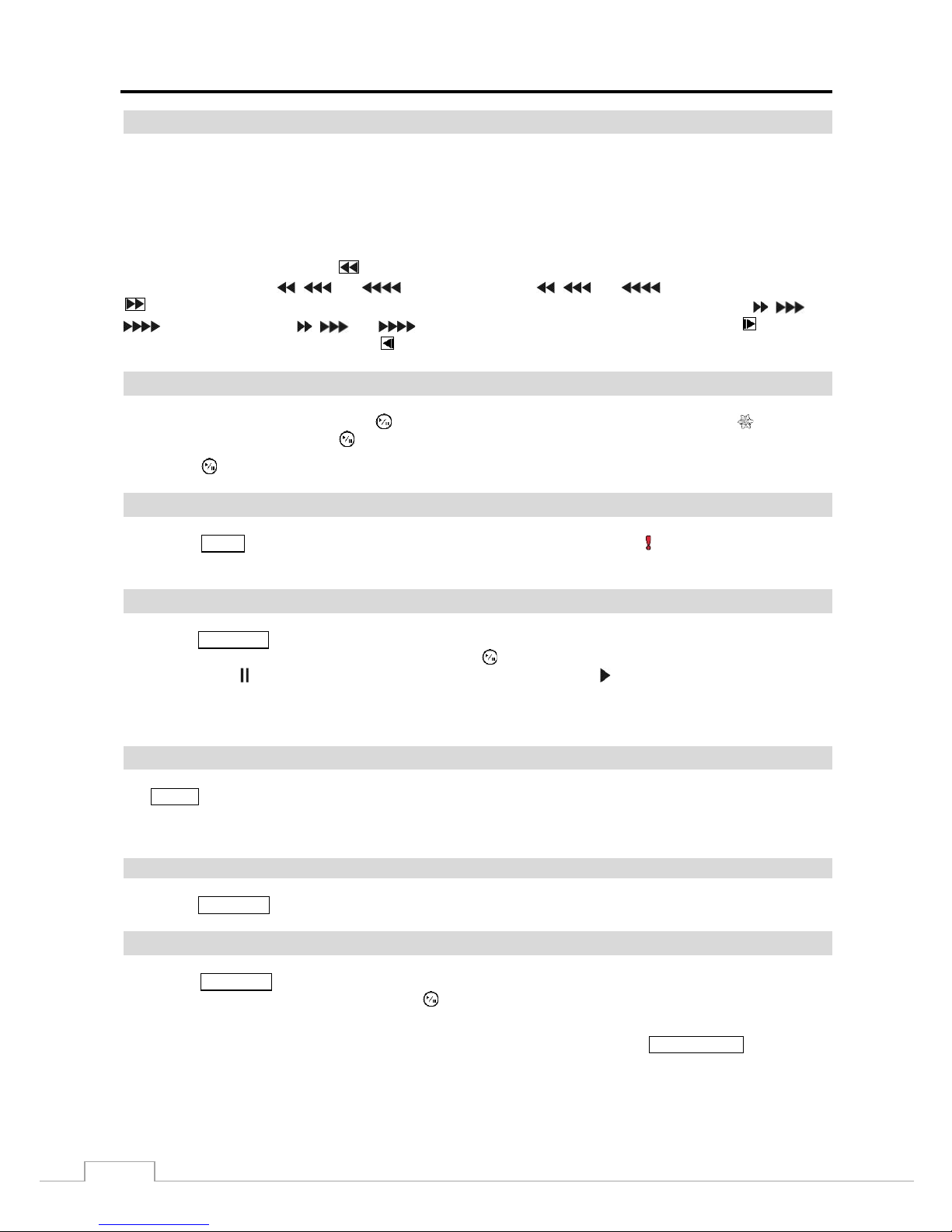
In the play back m ode, pres sing t he button play s vi deo backw ard a t high spe ed. Pre ssing the but ton a gain t oggl es
the playback speed from , and . The screen displays , and resp ectively. Pressing the
button plays video forward at high speed. Pressing the button again toggles the playback speed from , and
. The screen displays , and
respectively. When in the pause mode, pressing the button
moves to the next image and pressing the button moves to the previous image.
PLAY/PAUSE Button
In the live m onitori ng m ode, pressing the button f reezes the current screen and the screen displays icon. When
in the playback mode, pressing the button plays back images at regular speed or pauses playing video.
Pressing the button selects a highlighted item or completes an entry that you have made during system setup.
PANIC Button
Pressing the PANIC button starts panic recod in g of all camera channels, and displays on the screen. Pressing the
button again will stop panic recording.
PLAYBACK Button
Pressing the PLAYBACK button ent e rs t he pla y bac k m ode , a nd pres si ng the b utt on ag ai n ex its t he pla y bac k m ode . W he n
entering the pla yback mode , v i de o is pa us e d. Pressing the (Play/Pause) button plays ba ck video at reg ula r s pe e d.
The screen displays when the DVR is in the Pause mode and the screen displays when the DVR is playing back video.
When in one of the multi -view formats, pressing this button enters the Triplex mode. The DVR supports t he Triplex
function: monitoring, recording and playing back at the same time.
ALARM Button
The ALARM button has two functions. First, it will reset the DVR’s outputs including the internal buzzer during an
alarm. Second, it will display the event log when you are in the live monitoring mode unless there is an active alarm.
This operation can be user password protected.
CLIP COPY Button
Pressing the CLIP COPY button allows you to copy v ideo clips.
ZOOM/PTZ Button
Pressing the ZOOM/PTZ but ton z oom s in the current image in doubl e on the screen. You can use the ar row but tons to
move the rectangle to another area. Pressing the (Play/Pause) button zooms in the image in rectangle.
Pressing and holding the button for three seconds or longer enters the PTZ (Pan/Tilt/Zoom) mode and the PTZ icon
flickers . Pre s si ng t he button agai n e x i ts t he PT Z mode. Press i ng the arrow but tons or MENU/CAMEO button allows
you to control properly configured cameras.
Digital Video Recorder
11
ID Button on Remote Cont rol
If a DVR System ID is set to 0, th e infrared remote control will control that DVR without any additional operations.
(Refer to the System – General setup screen in this chapter for further information on setting the System ID.) If the
system ID is 1 to 16, y ou must to press the
ID button on the re m ote contr ol a nd the n pre ss t he num be r butt on ( 1 to 16)
in order to c ontr ol that DVR . If the System ID of two or more DVRs is set to 0, thos e D VRs will react to the infrared
remote control at the same time.
Bookmark Button on Remote Control
When in the playback mode, pressing the BOOKMARK button adds the curre nt play back point to t he book ma rk list or
moves to the registered bookmark point.
Turning on the Power
Connecting t he powe r cord t o the D VR turns on the uni t. The unit takes approximately one minute and 30 seconds to
initialize.
Initial Unit Setup
Before using your DVR for the first time, you will want to establish the initial settings. This includes items such as
time and date , dis pla y la ngua ge, cam e ra, rem ote contr ol, re cord mode, netw ork and pa ssw or d. Your DVR ca n be se t
up using various screens and dialog boxes.
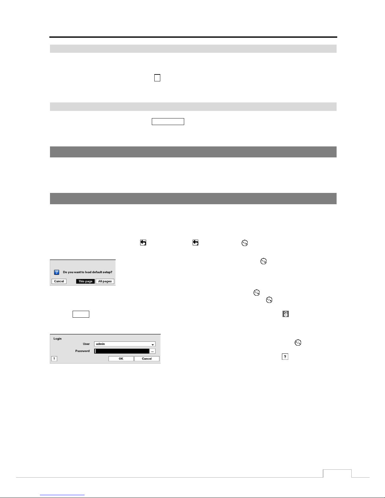
Throughout t he s c r e e ns y ou w ill s ee . Highlighting the and pressing the button gives you the op por tunity to
reset that screen to its default settings.
Highlighting This page or All pages and pressing the button resets the current
page or all pages o f the screen to its or their default settings.
After you are finished w ith any setup scree n, y ou ca n highl ig ht Save and press the button to save the changes and
exit the screen. If you do not wish to save the changes, highlight Cancel and press the button to exit the screen.
Press the MENU button or move the m ouse pointer on the rig ht e dge of the screen and then select (Login) in the Live
Monitoring menu to enter the setup screens. The Login screen appears.
Select a User and enter the password by pressing the appropriate
combination of Camera number buttons a nd the n the button. There
is no default pa s s word when log gi ng i n the admin user for the first
time. If you do not know the password, click the button for guidance.
Figure 5: Login screen.
User’s Manual
12
NOTE:
To assure the secure management of the system, setting up a password is strongly recommended.
If you cannot us e t he front panel butt ons , click the button using the mouse to enter a password, and
the virtual keyboard displays. See instructions below for using the virtual keyboard.
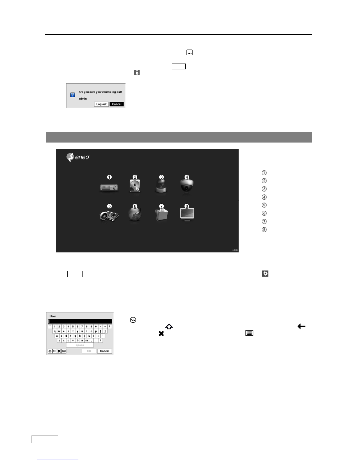
To log the user out of the system, press the MENU button or move the mouse pointe r on the righ t edge
of the screen and then select (Logout) in the Live Monitoring menu. The Logout screen displays asking
you to confirm whether or not you want to log out the current user.
Figure 6: Logout screen.
Setup Screen
System
Record
Event
Camera
Device
Network
Notification
Display
Figure 7: Setup screen.
Press the MENU button or move the mous e pointe r on the right edge of the screen and then select (Setup) in the Live
Monitoring menu to enter the setup screen.
While setting up the DVR, there will be many opportunities to enter names and titles. When making these entries, a
Virtual Keyboard will appear.
Use the arrow keys to highlight the character you want in the name or title and press
the button. That charac ter appears in the title bar and the c ursor moves to t he nex t
position. Pressing toggles between the upper and lower case keyboards,
backspaces, and deletes entered characters. Pressing toggles between different
keyboard layouts. You can use up to 31 characters incl uding spaces in your title.
Special characters can be created using ^ and a capital letter; e.g., ^J for NL (New
Line), ^M for CR (Carriage Return). Special characters are commonly used by text
input devices and will be useful when performing Text-In Searches.
Digital Video Recorder
13
System Setup
General
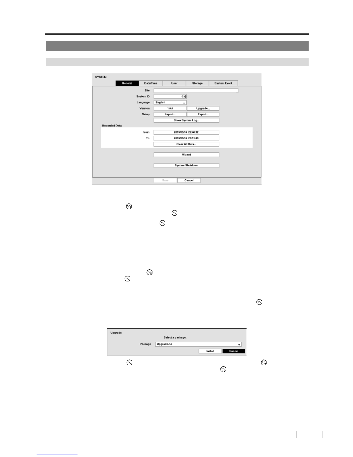
Figure 8: System – General setup screen.
Highlight the Site box and press the button. A virt ual keyboa rd appears that you ca n use to e nter a Site Name. Once
you have entered your title, highlight OK and press the button.
Highlight the box beside Syst em ID and press the button. Change the number by hig hlighting it and u sing the Up
and Down arrow buttons to increase and decrease the number from 0 to 99.
NOTE:
The System ID number is used to identify the unit when it is connected with other DVRs through the RS485
port. You cannot use the same ID number for two or more DVRs that are in the same RS485 network.
It is possible to have multiple DVRs with Sys tem ID 0 that are in the same area as long as they are not
part of an RS485 network. If this is the case, all will be controlled at the same time when using the infrared
remote control.
Highlight the box beside Language a nd press button. A drop-down menu displays the available languag es. Highlig ht
the desired language an d press the button.
The box beside Version displays the software version of the DVR. To upgrade the software, connect a USB device
containing the upg r a de pa cka ge fi le to t he DVR . If you enabled the NetFS function (Network menu > NetFS tab),
you can download the file from the registered NetFS site. Highlight Upgrade… and press the button. Select USB
Storage or NetFS. If you select NetFS, select a NetFS site f rom the registe red NetFS site list. The Upgrade screen
appears. The screen displays the upgrade package file names that are available. The “.rui” indicates that the file is for
software upgrades.
Select the desired file and press the button. Highlighting the Install button and pressi ng t he button will install
the selected software package. Highl ight ing the Cancel button and pressing the button will c los e the wind ow w ith ou t
upgrading the s oftwa re. If the upgrade package file is not ins tal led on the DVR prope rly , y ou wi ll ge t an er ror m es sage.
The system restarts automatically after completing the upgrade.
CAUTION:
The USB device must be FAT16 or FAT32 format.
User’s Manual
14
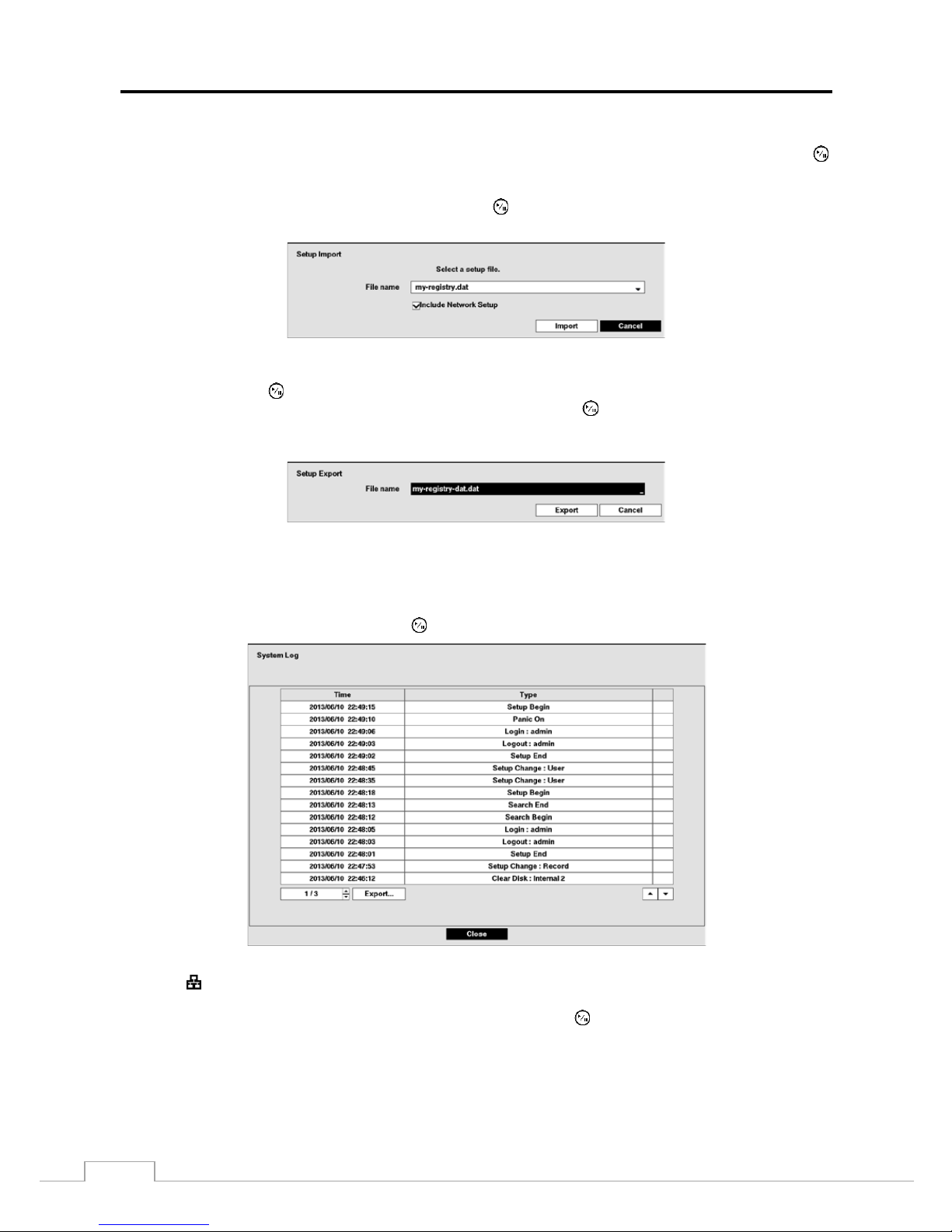
You can impor t s a v e d D VR setting s or e xport the curr ent DVR set tings. To import save d DVR setting s , c onne c t t he
USB device containing the setup file (.dat) to the DVR. If you ena bl ed the NetFS f uncti on (Network menu > NetFS
tab), you can download the setup file from the registered NetFS site. Highlight Setup – Import… and press the
button. Select USB Storage or NetFS. If you select NetFS, select a NetFS site from the registered NetFS site list.
Select the desired setup file and press the Import button to import the selected sett ings and change t he DVR settings
accordingly. Highlight Include Netw ork Setup and press the button to toggle between On and Off. When set to Off ,
the network settings will not be changed.
To export the current DVR settings, co nnect the USB device to the DVR. If you enabled the NetFS function
(Network menu > NetFS tab), you can upload the setup file on the registered NetFS site. Highlight Setup –
Export… a nd press the button. Select USB Storage or NetFS. If you select NetFS, select a NetFS site from the
registered NetFS site list. H ig hlight the box bes ide File name and press the button. A vir tual key board al lows y ou
to enter the file name. Selecting Export will save the current settings in .dat file format on the USB device or the
NetFS site.
NOTE:
Even after changing the DVR settings by importing saved settings, the time-related settings (Date/Time,
Time Zone and Daylight Saving Time) will NOT be changed.
CAUTION:
The USB device must be FAT16 or FAT32 format.
Highlight Show System Log… and press the button to display the System Log.
The System Log screen lists sy stem activities (up to 5,000 from the latest) that have occurred along with the time and
date. The
icon will be displayed in the last column f or system activities of the remote site. Y ou can s croll through
the log pag es by usi ng the Up an d D ow n ar row s, or y ou can g o dir ec tly t o a l og pag e by ente ring t he l o g pa ge num ber
in the box at the bottom left of the screen. Highlight Close and press the button to exit the screen.
Digital Video Recorder
15
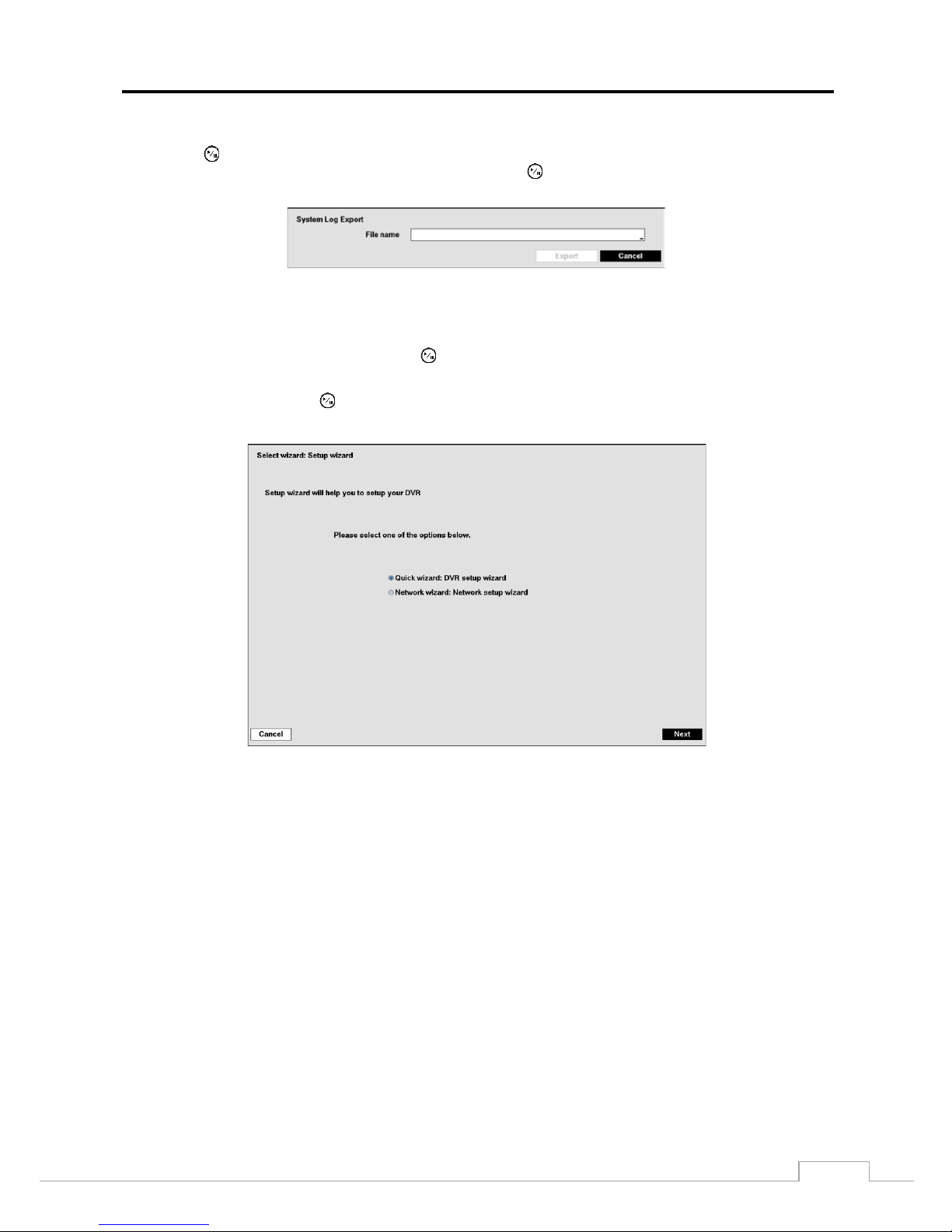
To export the sys tem log information, conne c t t he U SB de v ice t o the D VR. If you enabled the NetFS function
(Network menu > NetFS tab), you can u ploa d the log information on the re g iste re d NetFS site . Highlight Export…
and press the button. Select USB Storage or NetFS. If you select NetFS, select a NetFS site from the registered
NetFS site list. Highli ght the box bes ide File name and press the button. A v irtual k ey board allows you to e nter
the file name. Selecting Export will save the log inf ormation in .txt file f orma t on the U SB dev ic e or the NetFS site .
NOTE:
When opening the sav ed .txt file, settin g to the proper charac t er encoding and usin g fixed width fonts
will be required to read the file properly.
The box beside Recorded Data – From / To displays the time information of recorded data.
Highlighting Clear All Data… and pressing the button will clear all video data. You will be asked to verify that
you wish to clear all data befor e the DVR erases the video data. Clear All Data… will not clear the System Log.
Highlight Wizard and press the button. The Wizard setup screen appears. The Wizard setup guides you throug h
configuring the system for basic operation.
Select either Quick wizard or Network wizard and select th e Next button to start the selected setup wizard.
NOTE:
Selecting the Cancel button throughout the screens e xits the Qu ick Setup Wizar d without savin g y our
changes and returns to the main setup screen.
User’s Manual
16
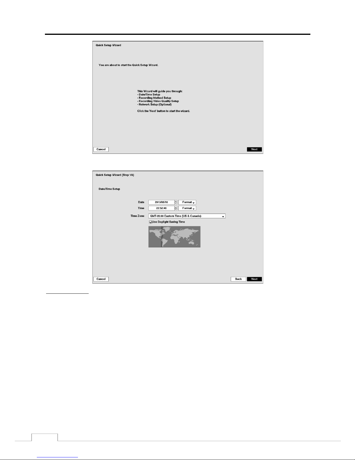
If you selected the Qu ick wizard, selecting the Next button starts the Quick Setup Wizard.
Date/Time Setup
Date: Set the system date and select the date format.
Time: Set the system time and select the time format.
Time Zone: Select your time zone. The Time Zone can be selected on the map.
Use Daylight Saving Time: Selecting the box sets the system to use daylight saving time.
NOTE:
The Date/Time will be set, and the clock will start when you click the Next button.
Digital Video Recorder
17
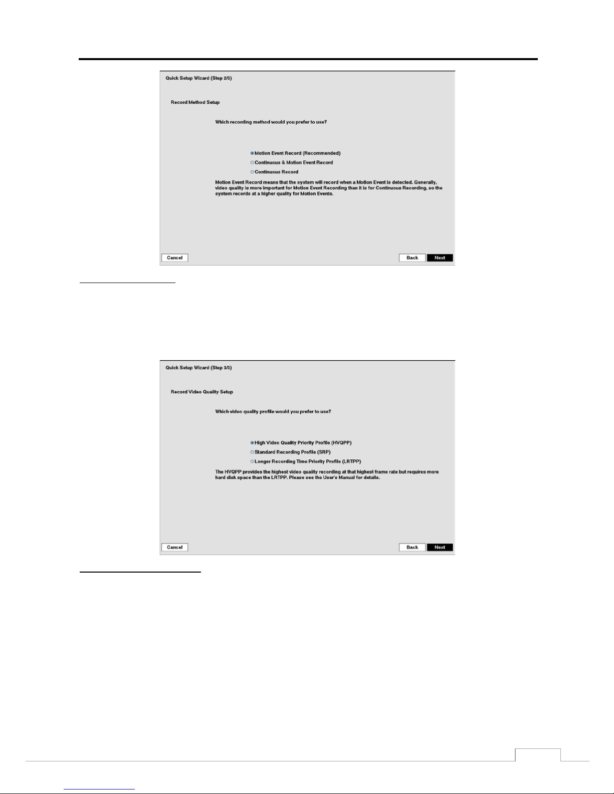
Record Method Setup
Select the desired recording mode from:
– Motion Event Record (Recommended)
– Continuous & Motion Event Record
– Continuous Record
NOTE:
You should understand each recording mode before setting the DVR’s recording method.
Record Video Quality Setup
Select the desired video quality profile from:
– Higher Video Quality Priority Profile
– Standard Recording Profile
– Longer Recording Time Priority Profile
NOTE:
The higher quality setting requires more storage space.
User’s Manual
18
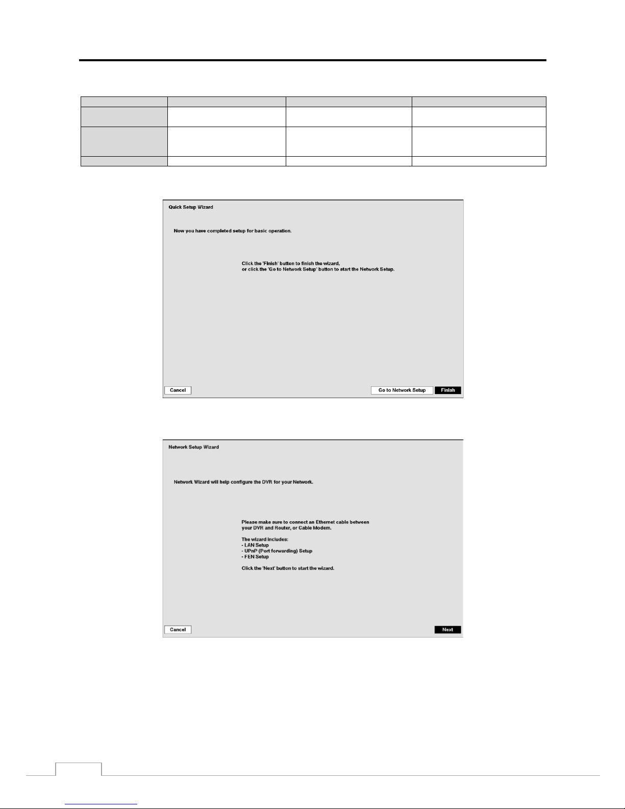
NOTE:
The recording quality, recording resolution, and recording speed of each camera channel will be set as
show below according to the Record Method and Recor d Vide o Q ual ity you set.
HVQPP*
SRP*
LRTPP*
Motion Event
Record
Very High / Very High / 30 ips High / High / 5 ips Standard / Standard / 3 ips
Continuous &
Motion Event
Record
Time, Event : Very High /
Very High / 30 ips
Time: High / Hi g h / 5 ips
Event: Very High / Very High /
30 ips
Time: Standard / Standard / 3 ips
Event: H igh / High / 5 ips
Continuous Record
Very High / Very High / 30 ips
High / High / 5 ips
Standard / Standard / 3 ips
* Record Video Quality: HVQPP (High Video Quality Priority Profile), SRP (Standard Recording Profile), LRTPP (Longer Recording Time
Priority Profile)
Select the Finish button to finish the Quick Setup Wizard and select t he Go t o Network Setup button to start the Network
Setup.
If you selected the Go to Network Setup, select the Next button to start the Network Setup Wizard.
Digital Video Recorder
19
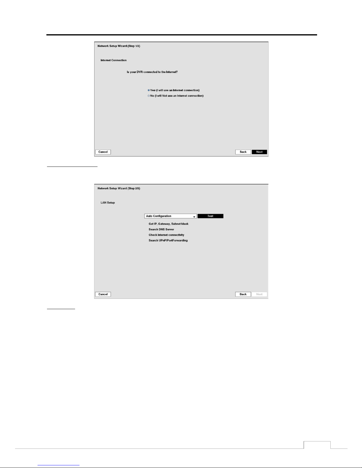
Internet Connection
Select whether or not your DVR is connected to the Internet.
LAN Setup
Select between Auto Configuration and Manual C onfiguration f or ne tw ork conf i gura tion, an d the n s el ec t the Test
button to test the ne twork configuration you selected.
NOTE:
Selecting Auto Configuration allows the DVR to automatically obtain LAN parameters (IP address, Gateway,
Subnet Mask and DNS Server address). Selecting Manual Configuration allows you to set up LAN
parameters manually.
The network configuration you set should be tested by selecting Test, otherwise the Next button will
cannot be selected, and you cannot move to the next step.

User’s Manual
20
FEN Setup
FEN Name: Enter the DVR name to be register ed on the FEN server.
NOTE:
The FEN Name you entered should be checked by selecting Test, otherwise the FEN change s will not
be saved.
When entering no name or a name already registered on the FEN server, an error message displays.
Select the Finish button to finish the Setup Wizard.
Highlight System Shutdown and press the button. The Shutdown screen displays asking you to confirm
whether or not you want to shut the system down.
After selecting Shutdown a nd press ing the button, a screen will appear telling you
when it is safe to disconnect power.
Digital Video Recorder
21
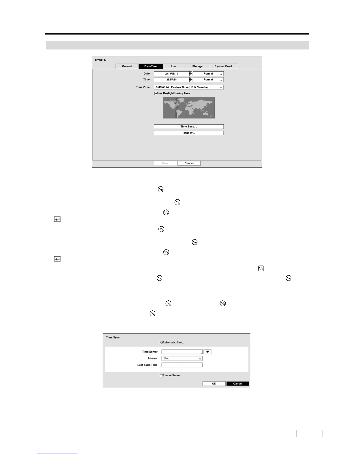
Date/Time
Figure 9: System – Date/Time setup screen.
Highlight the first box beside Date and press the button. The individual sections of the date will highlight. Use
the Up and Down arrow buttons to change the number . Use the Left and Right ar row butt ons to m ove between m onth,
date and year. Once you have the correct date, press the button.
Highlight the Form at box besi de Date and press the button. Select from the three available date formats and press
the button to save your selected format.
Highlight the first box beside Time and press the button. The individual sections of the time will highlight. Use
the Up and Down arrow butt ons to c hange the num ber. Us e the Left and Right arrow butto ns to m ove bet wee n hour,
minutes and seconds. Once you have the correct time, press th e button.
Highlight the Fo rm a t box besi de Time and press the button. Select from the three available time formats and press
the button to save your selected format.
NOTE:
The clock will not start running until you have highlighted Save and pressed the button.
Highlight the box beside Time Zone and pr ess the button. Sel ect your tim e zo ne fr om the li st a nd press the button.
NOTE:
The Time Zone can also be se lected on the map below by pressing the Left and Right buttons or scrolling
the mouse wheel up and down.
Highlight Use Daylight Saving Time and press the button. Pressing the button toggles between On and Off.
Highlighting Time Sync.… and pressi ng the button displays the Time Sync. screen. You can set up time
synchronizat ion between the DVR and standard time ser vers that are available in most time zones and countries, or
between the DVR and another DVR.
 Loading...