

Eneo TVD-2080V2812IR, TVD-1080V2812IR User Manual

EN
User Manual
1/2.8” HD-TVI Dome, Fixed,
Day&Night, 1920x1080, 2.812mm, Infrared, 3D-DNR,
12/24V
TVD-2080V2812IR

Safety Precaution
03
FULL-HD MEGA-PIXEL CAMERA
CAUTION: TO REDUCE THE RISK OF ELECTRIC SHOCK,
DO NOT REMOVE COVER (OR BACK).
NO USER SERVICEABLE PARTS INSIDE.
REFER SERVICING TO QUALIFIED SERVICE PERSONNEL.
To prevent fire or shock hazard, do not expose the unit to rain or moisture.
To prevent electric shocks and risk of fire hazards, do NOT use other than
specific power source.
Warning :
This equipment has been tested and found to comply with the limits for a Class
A digital device, pursuant to part 15 of the FCC Rules. These limits are designed
to provide reasonable protection against harmful interference when the equipment
is operated in a commercial environment. This equipment generates, uses, and
can radiate radio frequency energy and, if not installed and used in accordance with
the instruction manual, may cause harmful interference to radio communications.
Operation of this equipment in a residential area is likely to cause harmful
interference in which case the user will be required to correct the interference at
his own expense.
Caution :
Any changes or modifications in construction of this device which are not expressly
approved by the party responsible for compliance could void the user's authority
to operate the equipment.
Mains power quality should be that of a typical commercial environment. If the user
of the model requires continued operation during power mains interruptions, it is
recommended that the model be powered from an uninterruptible power supply
(UPS) or a battery.
The symbol is intended to alert the user to the presence of important
operating and maintenance(servicing) instructions in the literature
accompanying the unit.
The symbol is intended to alert the user to the presence of uninsulated
"dangerous voltage" within the product's enclosure that may be of
sufficient magnitude to constitute a risk of electric shock to persons.

FULL-HD MEGA-PIXEL CAMERA
Safety Precaution
NOTICE
The image used in this instruction manual are processed to help comprehension
and may differ from actual video of the camera.
Avoid installing areas where has shock or vibration which results in the problems.
Pay attention to safety when laying the connection cable and observe that the cable
is not subjected to heavy loads, kinks or damage and no moisture can get in.
Never open the device such as boards or lens.
The warranty becomes void if repairs are undertaken by unauthorized persons.
Maintenance and repair have to be carried out only by authorized service centers.
Use only a mild detergent to clean the housing.
The camera should never be operated beyond the technical specifications.
This can lead to destruction.
The camera should never be operated in water.
04

FULL-HD MEGA-PIXEL CAMERA
Contents
Safety Precaution
p.03~04
Contents
p.05
Features
p.06~07
Composition
p.07
Dimensions
p.08
Part Names
p.09
Installation Instructions
p.10~13
Operating Instructions
p.14~29
Specifications
p.30
05

FULL-HD MEGA-PIXEL CAMERA
Features
Key Features
• Full HD, 2Mega Pixel HD-TVI CAMERA, 1920x1080(30p/25p)
• TVI Video Transmission Distance over Coax.; 500M (RG59, 75Ω)
• Automatically removable IR Cut filter by Dual filter switcher
• Built-in f=2.8~12mm F1.4 Mega pixel DC Auto Iris Vari-focal lens
• True WDR(Wide Dynamic Range)
• Improved Noise figure with the enhanced 3D-NR
• Pointing Zoom which enables the flexible zooming at any area.
• Smart Motion Zoom in combining with Pointing Zoom.
(Automatic zoom in/out when motion is detected)
• Preset Zoom
• Motion Detection, Privacy Mask, Defog, Sens-up(x32), D-WDR,
H/V/HV Flip, D-Zoom(1.1x~8x), LSC(Lens Shade Compensation),
BLC/HLC, Pixel Defect Compensation, Title Set
• Top performance at low light sensitivity (Sens-up On)
• Video output HD-TVI or CVBS switchable
• OSD MENU & Video Sub-out port for easy installation & maintenance
• Circuit protection against faulty connection in power polarity
• Isolated power supply against ground loop problem
• Remote control via RS-485 (Pelco-D/P)
• UTC Control through HD-TVI DVR
• Zoom & Focus Adjustment on 3-Axis Gimbal
• Built-in 30pcs IR-LED
• Flush mount (Option: Surface mount and Various adaptors)
• Double side Anti-Scratch Hard coated clear bubble dome
• IP67 / IK10 Protection
• AC24/DC12V Dual power
06
FULL-HD MEGA-PIXEL CAMERA
General Description
• With ICR mechanism,
- Enhances its sensitivity about 10x at night time
- Can accepts the infrared light
• With Intelligent Focus Indicator and FOCUS ASSIST menu,
- Offers easy adjustment of Focus
- Eliminates the mistake of the erratic focus adjustment
• With 24VAC/12VDC dual power design,
- Offers the flexibility of installation
- Ensures the reliability
This camera realizes the natural and crisp image as you see the scene in front
of you by Full HD(1920x1080p) camera module.
Highly detailed pictures can be achieved and color reproducibility deserves
attention.
07
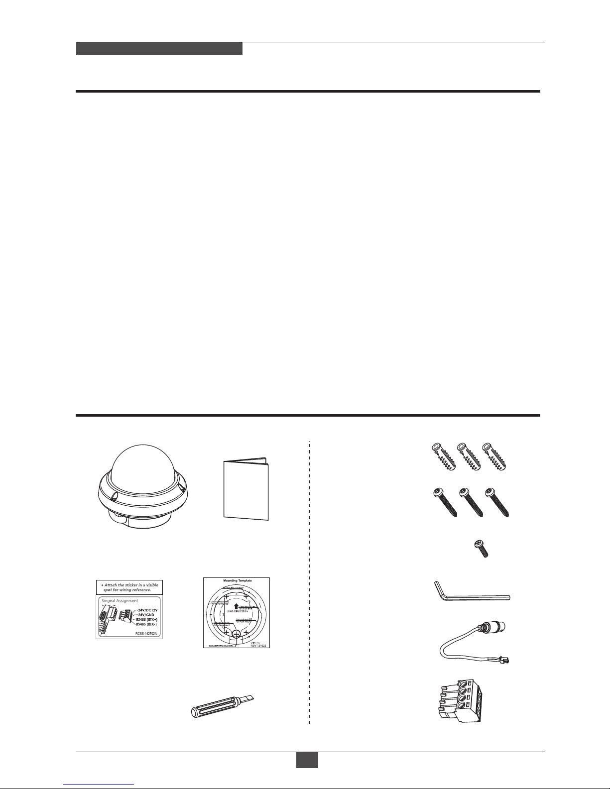
Composition
Features
Mounting Template
Cable Signal
Sticker
Operating
Instruction
Torque Wrench:
3mm (1pc)
Video Sub-out
Cable (1pc)
Mounting Screw:
4 x 30mm (3pcs)
Plastic Anchor:
6 x 30mm (3pcs)
Dome Camera
Focus adjust
Driver (1pc)
Wiring Connector
(1pc)
Connector fixing Screw:
2.5 x 5mm (1pc)
FULL-HD MEGA-PIXEL CAMERA
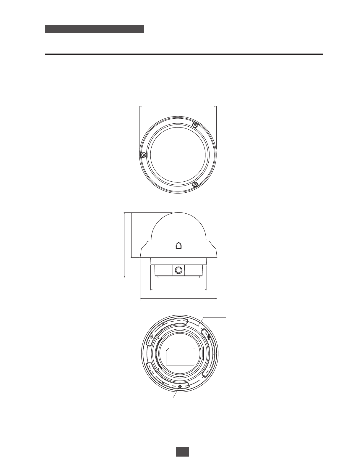
Dimensions
(unit : mm)
08
Ø140
119
PCD Ø120
Ø102
Ø140
3-Ø4.2
82
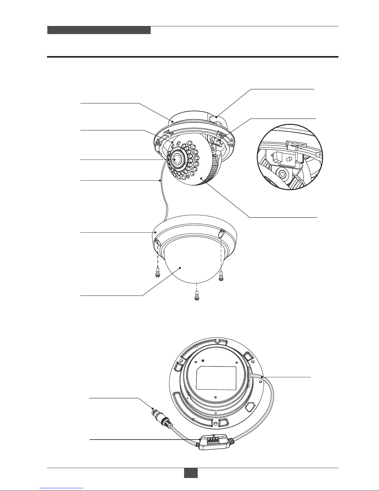
Part Names
FULL-HD MEGA-PIXEL CAMERA
09
BUBBLE DOME
3-AXIS GIMBAL
DOME COVER
SAFTY WIRE
VIDEO (BNC)
FLUSH MOUNT
FOCUS / ZOOM
LENS
POWER CABLE
POWER CABLE
[ BOTTOM VIEW ]
OSD CONTROL
JOY STICK
POWER SUPPLY
CONNECTOR
POWER
CABLE
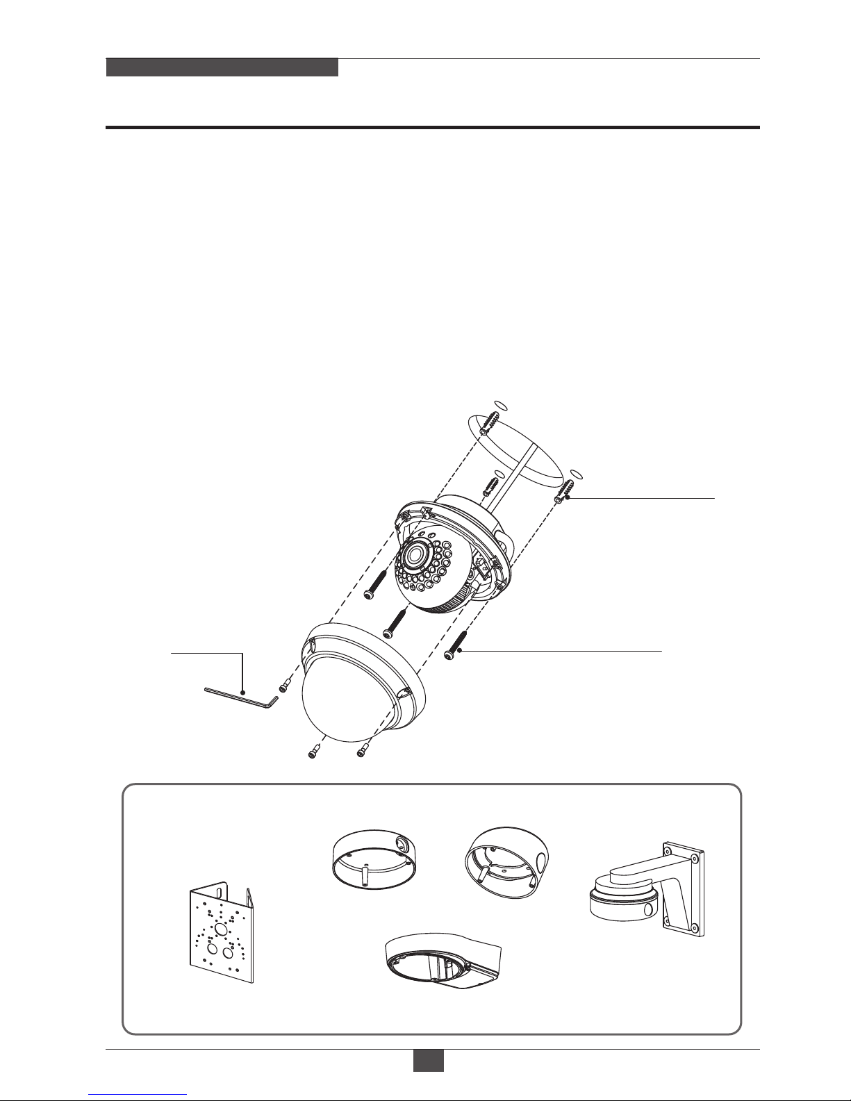
Installation Instructions
FULL-HD MEGA-PIXEL CAMERA
10
1. Locate the mounting template at the installation position and drill the ceiling
or wall if needed.
2. Open the dome cover by loosening screws(4x12mm). Use the torque wrench
supplied.
3. Set the camera’s viewing angle and adjust zoom/focus of lens by using the focus
driver.
4. Put the dome cover to the dome base unit and tighten the assembly screws.
- Place the dome base unit on pre-drilled position and fix it through using mounting
screws (4x30mm).
- Route the power cable to the connecting place.
• Surface mount
• Pole mount adaptor
• Tilted mount
• Wall mount
(Requires additional
Surface mount)
• Tilted junction mount
■ Optional Mounting Accessories
Mounting Screw
(4x30mm)
Plastic Anchor
(6x30mm)
Torque
Wrench
 Loading...