

Eneo Rapport III, Rapport III-Pro Instruction Manual
eneo
®
is a registered trademark of Videor E. Hartig GmbH
Exclusive distribution through specialised trade channels only.
Videor E. Hartig GmbH
Carl-Zeiss-Straße 8 · 63322 Rödermark, Germany
Tel. +49 (0) 6074 / 888-0 · Fax +49 (0) 6074 / 888-100
www.videor.com
Technical changes reserved
© Copyright by Videor E. Hartig GmbH
01/2011
Before attempting to connect or operate this product, please read these
instructions carefully and save this manual for future use.
Instruction Manual
Multifunctional CCTV Tester
Rapport III
Rapport III-Pro

TABLE OF CONTENTS
Information .................................................................4
Before Using Rapport III ...........................................5
Safety Information......................................................6
Product Introduction................................................10
Major functions of Rapport III.................................10
Standard item.........................................................11
Introduction ............................................................12
Product Specification ..............................................18
General specification .............................................18
Meter specification .................................................19
Functional Specification..........................................20
Power ON/OFF ......................................................20
Mode setup ...........................................................21
Video tester ...........................................................22
DVR function..........................................................25
Digital multimeter ...................................................34
PTZ controller .......................................................38
UTP cable tester ....................................................41
Symbols....................................................................43
Drawing.....................................................................44
03
INFORMATION
General
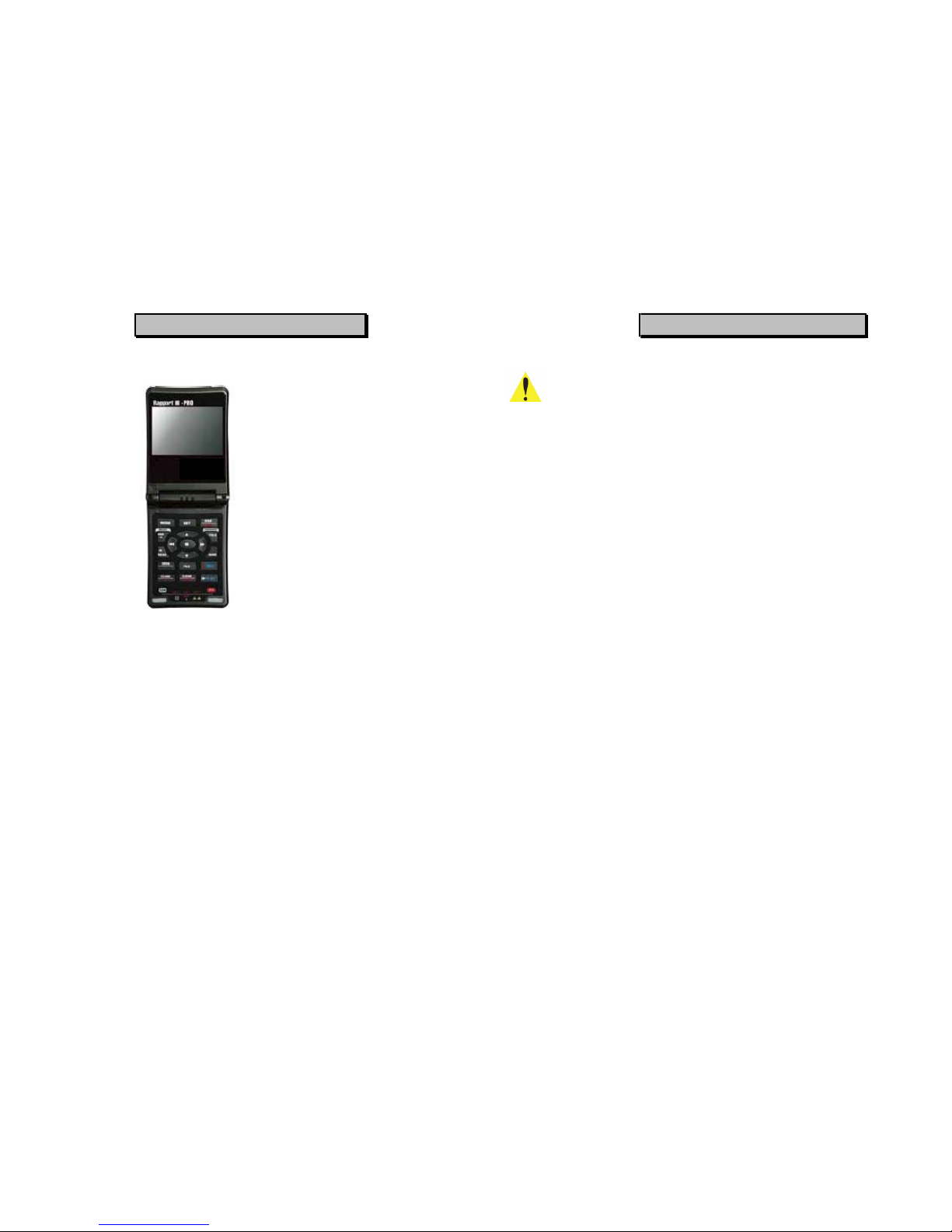
■ Rapport III is a Portable Service
Monitor & Multimeter with a built-in 3.5
inch digital monitor.
■ It's a simple and convenient multi-
functional measurement and test tool
which provides monitoring and
analytical data when installing CCTV
systems
Product Functions
■ Video Input and Output
■ Multimeter (Voltage and Resistance)
■ Cable Test (UTP)
■ PTZ Control
■ Video Storage Function (DVR, Rapport
III - PRO)
■ Operating Temperature: -10T: ~ 50T:
■ Relative Humidity: 30% ~ 90%
■ Recharge Voltage: 12V ± 10%, 1.2 A or
above
*Normal operation: Without using DVR and
Multimeter
*The Rapport III and Rapport III Pro support the same basic functions,
but the Rapport III does not include the DVR function.
BEFORE USING RAPPORT III
General
Be sure to read through the "Safety Information" section before using this
Rapport III.
This basic instruction manual is for users of the Rapport III. Starting with an
outline of this Rapport III, the manual explains its operation, how it connects to
other devices, how to use the menu buttons, and how it should be operated.
It is highly recommended, even for those who have handled similar devices, as
well as for those using it for the first time, to read all the instructions thoroughly,
especially the precautions, before using the Rapport III.
If there are any questions which arise when using the Rapport III or the unit is
damaged, please contact the supplier of your Rapport III.
Safety Information highlights and explains the precautions which should be
taken, for the safety of Users, when using the Rapport III.
Introduction to the Rapport III, explains the available features and appearance.
Specifications of the Rapport III, explains the specification of the Rapport III.
Functional Use, details the functions of the Rapport III and explains their uses.
04 05
SAFETY INFORMATION
Precautions
The following describes how to safely operate the
Rapport III.
Please read carefully "the precautions for use of this product" prior to
using this device. Check the input and output ranges of any voltages
being applied to all inputs and outputs of the device, and ensure their
connections have been made properly so no abnormal load is placed
on the operation of the device. If the measurement value is unknown
when measuring a resistance, set the Rapport ill meter to its maximum
value so that no abnormal load is placed upon the device.
The Rapport in should only be used under the environmental
conditions shown in the specification where temperature and humidity
figures should be adhered to.
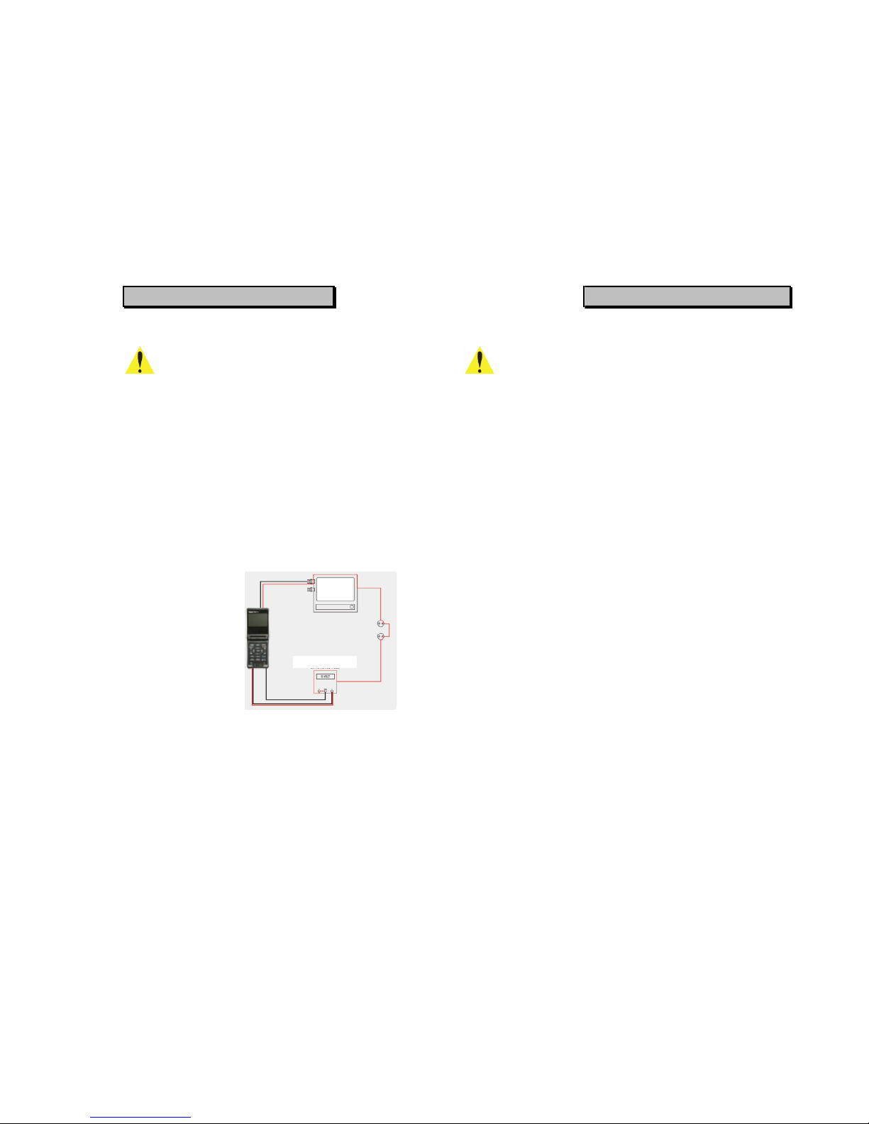
Before using the
multimeter function for
circuit testing, always
disconnect all Video
In/Out connections made
to any other external
devices. Connecting the
Test Lead Set to a circuit
for testing, with these
connections made,
causes them to use a
common grounding path
and could result in
damage to the device.
SAFETY INFORMATION
Precautions
Pay attention to the following precautions when using the
Rapport III.
■ Do not use the unit in damp, humid or gaseous environments.
■ Do not touch it with wet hands.
■ Be mindful not to shock or shake the unit while in use to avoid damage.
■ Avoid areas with strong magnetic or electromotive fields, which can cause
incorrect measurements or operability.
■ Do not expose the ports or joints to dirt or liquids.
■ Do not disassemble the Rapport ill.
■ Do not use the meter function, if the Rapport ill or the Test Lead set look
damaged.
■ Do not measure resistance when power is applied to a circuit.
■ When using the meter function, do not forget to turn on the power to
■ the Rapport ill and use the correct measurement range before connecting to
a circuit to be measured.
■ Turn off the power to the circuit under test and discharge all high voltage
capacitance before starting resistance or continuity tests to avoid damage to
the Rapport ill.
■ Place fingers behind the protecting pad when using a test probe.
06 07
MONITOR
DC POWER SUPPLIES
SAFETY INFORMATION
Precautions
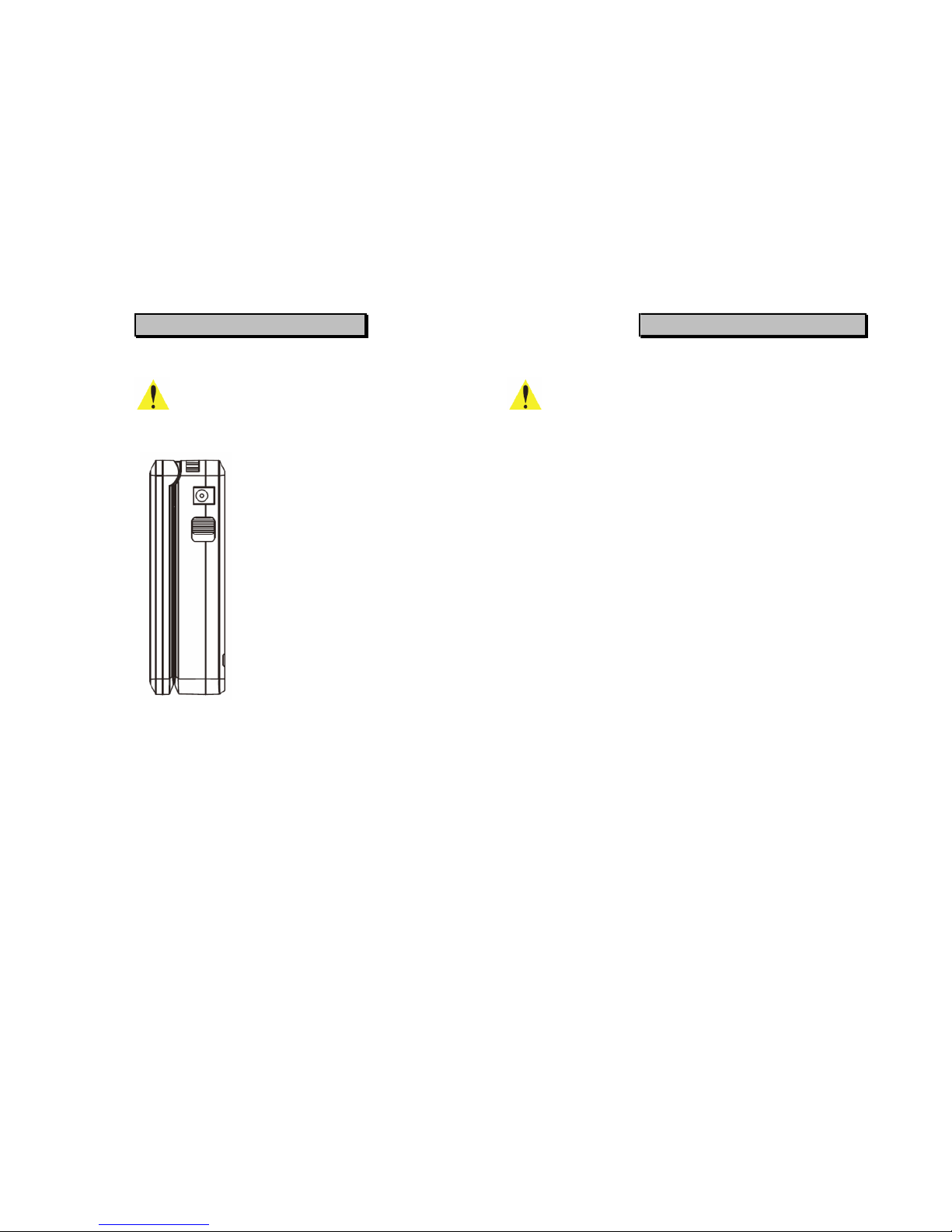
Battery Charging Precautions
The Rapport ill has a built-in Lithium
Polymer Battery. It can be recharged
using a DC12V power adapter with an
output of 1.2A or above and reaches
its full charge after a period in excess
of 6 hours. After the battery has been
fully charged for the first 2-3 charging
cycles, it can be used for
approximately 6 hours (up to a Max.8
hrs in normal operation).
The battery can be recharged by
connecting it to the DC adapter,
regardless of OSD power, when the
slider switch has been turned on.
The discharge operation starts when the Main Switch is turned on and it then
consumes power from the battery. Therefore, when the Rapport ill is not being
used for a period of time, make sure the Main Switch is turned off.
SAFETY INFORMATION
Precautions
Battery Handling
■ Avoid short circuits, as this will cause internal damage to the battery.
■ The soft packaging can easily be damaged by contact with sharp surfaces
or objects, take care when handling or storing.
■ The sealed edge adjacent to the battery contacts is a very sensitive area;
take care not to bend or fold the edges.
■ Do not open the folded edges.
■ Do not bend the tabs are these are breakable.
■ Avoid mechanical shocks to the battery.
■ Do not immerse the battery in water.
■ Only use the supplied battery charger or one with a safety guarantee.
■ Stop charging immediately if the battery is overheating, emitting a burning
smell, changed in colour or distorted.
■ Keep away from static electronic fields while using, charging or when
storing.
■ Do not disassemble; the battery is not a serviceable item.
■ Never short circuit the positive and negative poles of the battery.
■ Do not charge the battery in ambient temperatures above 40°C/104°F
08 09
PRODUCT INTRODUCTION
Summary
Designed, with portability and serious CCTV engineers in mind, the
Rapport in is an advanced piece of video test equipment consisting of
many useful test functions needed to professionally install a CCTV
system; test functions include Video Level, Service Monitor,
Multimeter, UTP Test, PTZ Test, RS-422 and RS-485 Communication
Test, etc.
Major Functions of Rapport III
■ Video Testing
¾ Tests whether a video image is present, and its quality, by
displaying the image on the built-in 3.5" Digital Monitor.
¾ Conducts and displays the Video Level (IRE test) of the image.
¾ Video signal generator Mode: It outputs a Colour Bar which
allows the engineer to test a video monitor or DVR. Rapport ill
supports both PAL & NTSC video signal format.
■ DVR Function (This funtion is only supported by the Rapport m-PRO)
¾ Store the video input on to a SD Card and play it back.
■ Meter
¾ Functions for testing voltage, resistance and short circuits.
■ PTZ Protocol Analyzer
¾ It determines which protocol controls a PTZ camera from a PTZ
Controller or DVR. This helps the CCTV Installer to understand
the protocol and find faulty devices.
■ UTP Cable Testing
¾ Test the integrity of connection conditions of a Category 5e UTP
cable. Checks for continuity or short circuits.
PRODUCT INTRODUCTION
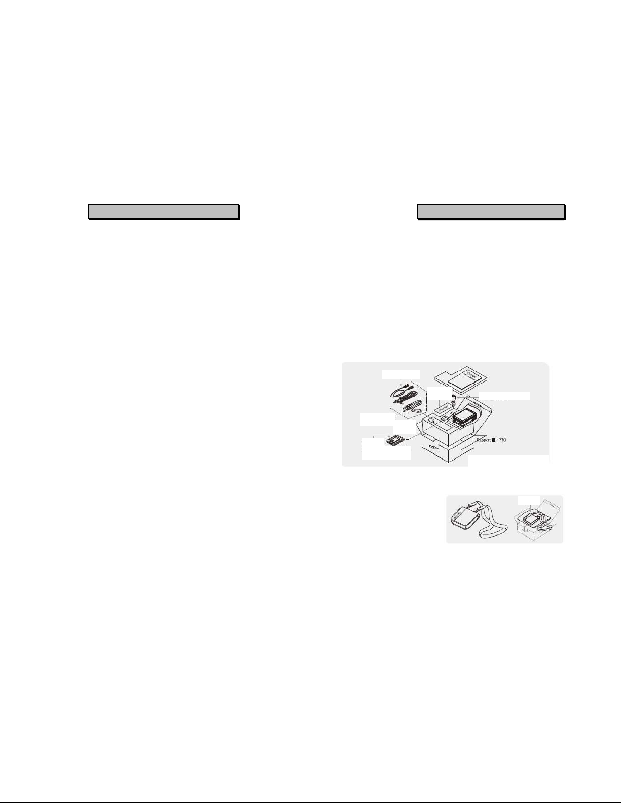
Standard Items
Check the contents of your Rapport ill package against the standard checklist
below:
Rapport ill Main Test Unit
■ SD Card (2Gb Storage) - (optional,
Rapport m-PRO)
■ Test Lead Set (1 x Red Lead, 1 x Black
Lead)
■ Rechargeable Lithium Polymer Battery
(7.4V 2000mA)
■ UTP Test Terminal - Dongle
■ User Manual
■ Power Adapter (DC12V)
■ Safety Strap
■ BNC Video Cable
■ Tester Carry Bag
10 11
BNC Video cable
Bag
UTP Tester Terminal
Test Lead Set
SD Card
* SD Card is porvided to
Rapport III-PRO only.
Safety
Strap
Power
Adaptor
Rapport III Package
PRODUCT INTRODUCTION
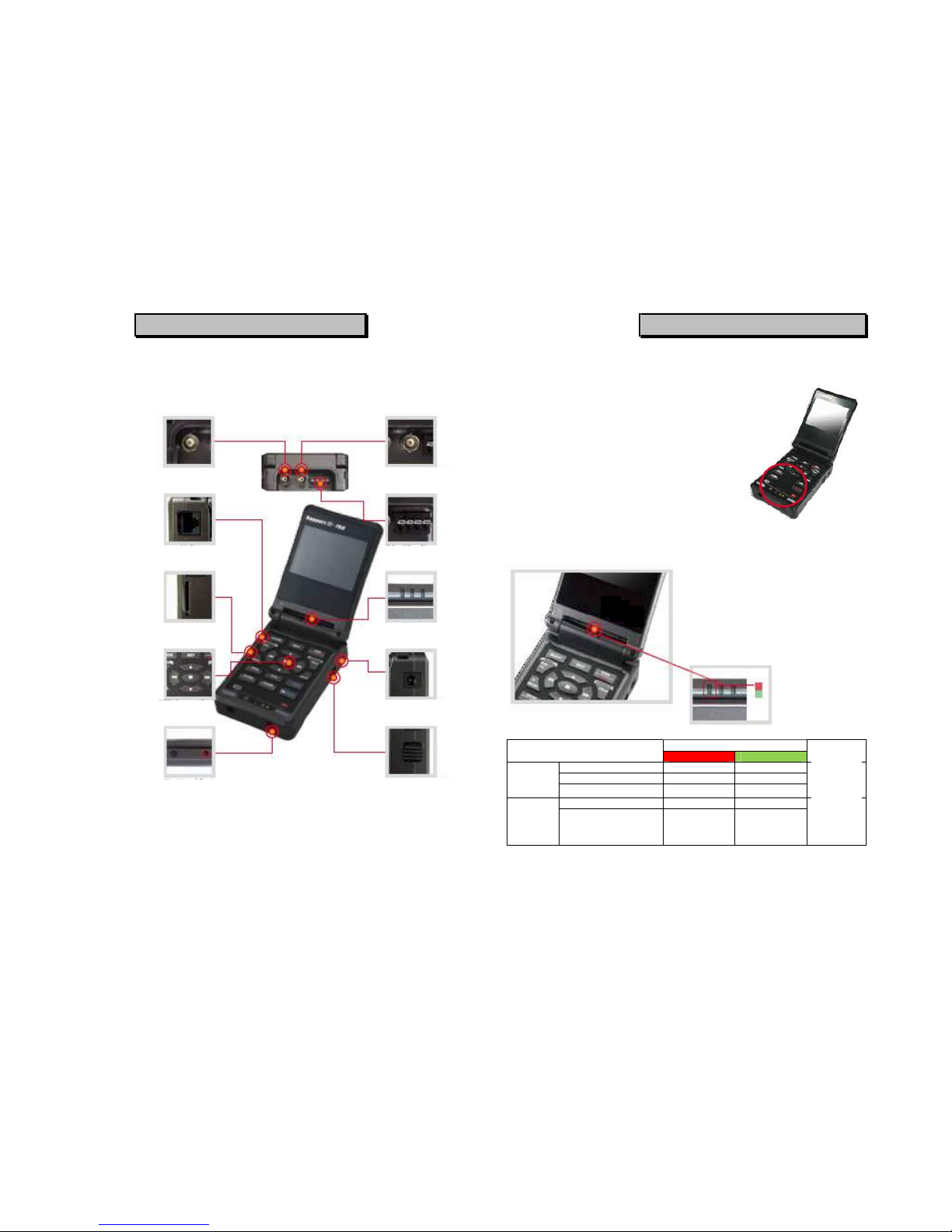
Introduction
PRODUCT INTRODUCTION
■ Rapport III (without DVR function)
The Rapport III and Rapport Ill-Pro support
the same basic functions, but the Rapport III
does not include the DVR function
LED Indicator
Power LED Item
RED LED GREEN LED
Remark
Charging ON OFF
Fully charged OFF ON
Charging
mode
Charging error OFF OFF
Adaptor
connected
Operating ON OFF Operating
mode
Low battery Flicker OFF
Adaptor
disconnect
ed
*This is for power LED status when the power switch is ON.
12 13
■ The LED turns Red or Green depend on
the recharging status.
On charging: RED LED ON
Fully charged: GREEN LED ON
■ When operating the Rapport without an
adapter.
On operating: RED LED ON
Low battery: RED LED flickers on and
off
BNC Video Input
BNC Video Output
UTP Input RS-485 In/Out
SD Card Slot
LED Indicato
r
PowerInput DC12V
PTZ Control Pad
Test Lead Port
Main Power Switch
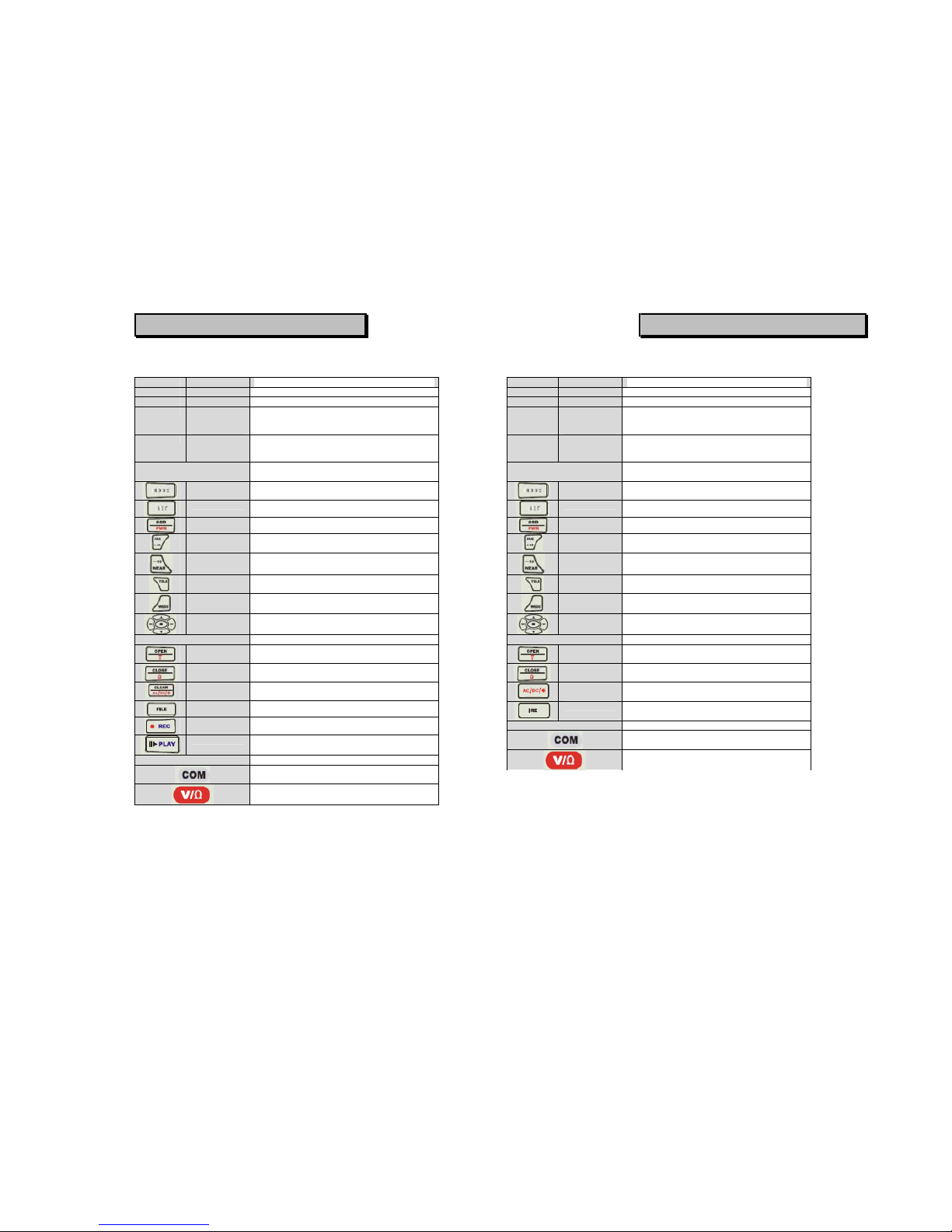
PRODUCT INTRODUCTION
Rapport III-Pro
Part Name Function
À LCD TFT LCD
Á POWER Red LED is on when the OSD POWER is on
 Data
Transmitting
LED
Red LED is on when Data is Transmitted
à Data
Receiving
LED
Red LED is on when Data is Received
Ä Key Button For Controlling External Devices i.e. Rapport
III
MODE Button Used to Change Setup
SET Button OSD Selection
OSD Button It toggles OSD & POWER on/off
FAR Button Adjusts PTZ Focus (Far Direction) & Increases
Video Image Brightness
NEAR Button Adjusts PTZ Focus (Near Direction) & Decreases
Video Image Brightness
TELE Button Zooms PTZ (Zoom In) & Increases Video Image
Contrast
WIDE Button Zooms PTZ (Zoom Out) & Decreases Video
Image Contrast
Shift Setup
Button
Moves PTZ Up, Down, Right, Left & Also Used for
Menu Functions
Å Key Button METER
Voltage
Button
Measures Voltage
Resistance
Button
Measures Resistance
Setup Change
Button
Changes setup Between AC & DC,
Resistance/continuity Test
FILE Image data list for SD card {Rapport Ill-PRO)
• REC Record Video (Rapport m-PRO)
PLAY Playback Recoded Video (Rapport m-PRO)
Æ Test Lead Connection Test Lead Connection Positions
Position of Black Test Lead, Common Ground (-
ve)
Position of Red test Lead for Measuring Voltage &
Resistance (+ve)
PRODUCT INTRODUCTION
Rapport III
Part Name Function
À LCD TFT LCD
Á POWER Red LED is on when the OSD POWER is on
 Data
Transmitting
LED
Red LED is on when Data is Transmitted
à Data
Receiving
LED
Red LED is on when Data is Received
Ä Key Button For Controlling External Devices i.e. Rapport
III
MODE Button Used to Change Setup
SET Button OSD Selection
OSD Button It toggles OSD & POWER on/off
FAR Button Adjusts PTZ Focus (Far Direction) & Increases
Video Image Brightness
NEAR Button Adjusts PTZ Focus (Near Direction) & Decreases
Video Image Brightness
TELE Button Zooms PTZ (Zoom In) & Increases Video Image
Contrast
WIDE Button Zooms PTZ (Zoom Out) & Decreases Video
Image Contrast
Shift Setup
Button
Moves PTZ Up, Down, Right, Left & Also Used for
Menu Functions
Å Key Button METER
Voltage
Button
Measures Voltage
Resistance
Button
Measures Resistance
Setup Change
Button
Changes setup Between AC & DC,
Resistance/continuity Test
IRE Measures Video Level
Æ Test Lead Connection Test Lead Connection Positions
Position of Black Test Lead, Common Ground (-
ve)
Position of Red test Lead for Measuring Voltage &
Resistance (+ve)
14 15
 Loading...