


Quick Installation Guide
1/2.5“ Fisheye Network Camera
PXD-5360F01IR
PXD-5362F01IR
DE
EN
FR
PL
RU

Inhalt
Inhalt ..........................................................................................................................2
Sicherheitshinweise .................................................................................................3
Lieferumfang .............................................................................................................3
Produktbeschreibung und Anschlüsse ................................................................4
Installation .................................................................................................................6
Spannungsversorgung der Kamera .......................................................................7
Ethernet Kabel Anschluss ......................................................................................7
Netzwerk Konfiguration ...........................................................................................8
ActiveX-Steuerelemente und Plug-Ins ...................................................................8
Internet Explorer Sicherheitsstufen ........................................................................8
Zugriff auf die Kamera ............................................................................................9
Login ID & Passwort ..............................................................................................9
ActiveX-Steuerelement installieren .......................................................................9
Browser-basierter Viewer ................................................................................... 10
Weitere Informationen ......................................................................................... 10
22
Sicherheitshinweise
Bitte beachten Sie auch die beiliegenden Sicherheitshinweise und lesen Sie
diese Anleitung vor Inbetriebnahme sorgfältig durch.
Wichtige Hinweise sind mit einem Achtungsymbol gekennzeichnet.
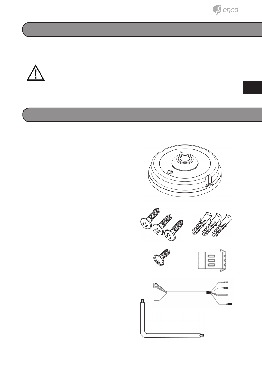
Lieferumfang
● 1x Fisheye Netzwerk Kamera
● 1x Installations- und Betriebsanleitung
● 1x Torx Schlüssel
● 3x Montageschrauben
● 3x Kunststoffdübel
● 1x Sicherheitsschraube
● 1x Strom Anschlussblock
● 1x Kabelpeitsche
● 1x Remote Viewer Software
DE
DE
EN
EN
FR
FR
PL
PL
RU
RU
3
3
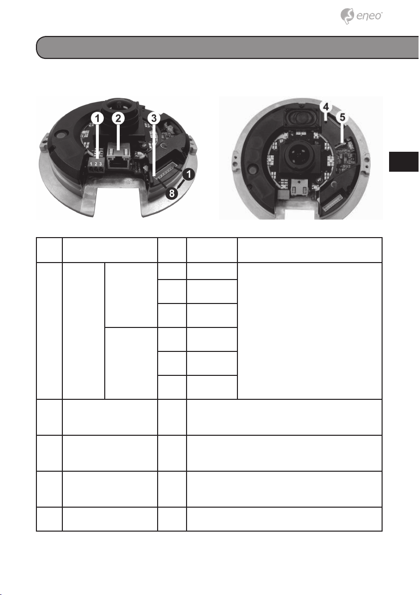
Produktbeschreibung und Anschlüsse
Nr. Anschluss Pin Defi nition Bemerkungen
1 Strom* 12V DC 1 Strom Stromanschluss
2 Reserviert
3 Masse
24V AC 1 Strom-1
2 Masse
Strom-2
2 RJ-45 - 10/100 Mbps Ethernet / PoE (PXD-
5360F01IR)
3 Alarm & Audio I/O* - Weiteres zu the Alarm & Audio I/O fi nden Sie
im Benutzerhandbuch in der Tabelle unter
Cable Defi nition
4 Reset Knopf -
Schlitz für Micro SD
5
Card
Zurücksetzen auf Werkeinstellungen
Drücken Sie den Knopf mit einem passenden
Werkzeug.
Zur Speicherung der Videoaufnahmen
-
*All in One Cable is required for Power, Alarm and Audio I/O utilization
44
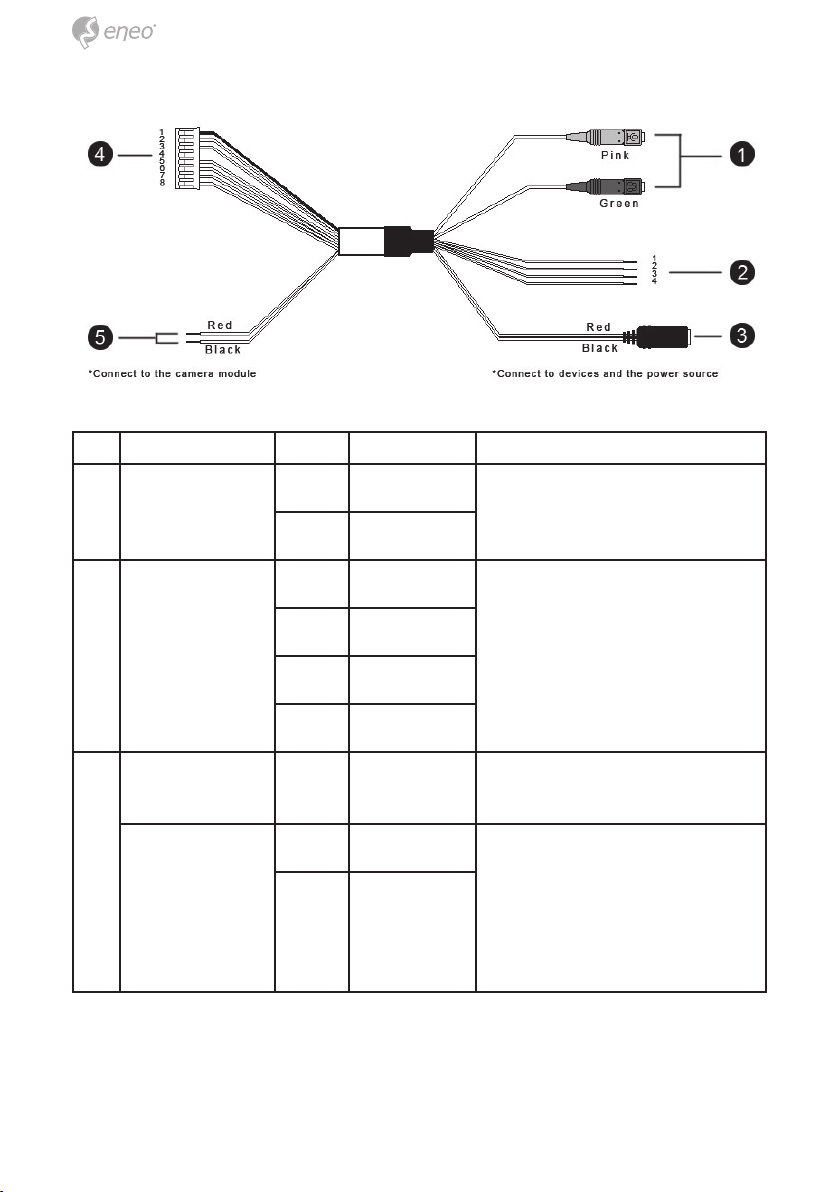
Nr. Anschluss Pin Definition Bemerkungen
1 Audio I/O Rosa Line In Bi-direktionale Audioübertragung
Grün Line Out
DE
DE
EN
EN
FR
FR
PL
PL
RU
RU
2 Alarm (4-Pin
Anschlussblock)
3 Hohlstecker - 12V DC Stromanschluss (Tip: +, sleeve: -)
Stromkabel Rot 24V AC (+) Remove DC Jack connector
1 ALM_IN – Alarmanschluss
2 ALM_IN +
3 ALM_OUT –
4 ALM_OUT +
head, and apply AC 24V with
Schwarz 24V AC (–)
Red and Black wires.
Please refer to the section of
Cable Definition in User’s Manual.
5
5
Nr. Anschluss Pin Definition Bemerkungen
4 Alarm & Au-
dio I/O
5 Stromkabel Rot 12V DC (+) /
1 Masse Bi-direktionale Audioübertragung
2 Line In
3 Line Out
4 -
5 ALM_IN –
6 ALM_IN +
7 ALM_OUT –
8 ALM_OUT +
24V AC (+)
Schwarz 12V DC (–) /
24V AC (–)
/ Alarmanschluss
Stromanschluss
Installation
1. Bohren Sie zwei Löcher, entsprechend dem Abstand der Montagelöcher
in der Bodenplatte, in Decke oder Wand.
2. Setzen Sie die Dome-Basis an die Stelle mit den vorgeborten Löchern
und befestigen Sie sie mit den Montageschrauben durch die Montagelöcher.
3. Setzen Sie die Abdeckung auf die Dome-Basis und ziehen Sie die
Schrauben mit dem Torx-Schlüssel fest.
66
Spannungsversorgung der Kamera
Um die Kamera mit Spannung zu versorgen, schließen Sie bitte das 12VDC
/24VAC-Kabel der Kamera an den Strom Anschlussblock an. Alternativ verbinden Sie das Ethernetkabel mit dem RJ-45 Port der Kamera und schließen Sie das andere Ende an einen PoE Switch an.
HINWEIS: Bei der Verwendung von PoE stellen Sie sicher, dass
ein Spannungsversorgungsgerät (PSE) im Netzwerk vorhanden ist.
Ethernet Kabel Anschluss
Verbinden Sie ein Ende des CAT5 Ethernet Kabels mit dem RJ-45 Anschluss der IP Kamera und das andere Ende mit einem Netzwerk Switch
oder PC.
HINWEIS: In manchen Fällen wird ein Cross over Ethernet Kabel
benötigt, wenn die Kamera direkt mit dem PC verbunden werden
soll.
HINWEIS: Prüfen Sie den Status der Verbindungs- und Übertragungs-LED. Wenn die LED nicht leuchten prüfen Sie bitte die LAN
Verbindung.
DE
DE
EN
EN
FR
FR
PL
PL
RU
RU
Das grüne Verbindungs LED zeigt eine bestehende Verbindung
an.
Das orangene Übertragungs-LED zeigt Datenübertragung durch
Blinken an.
7
7

Netzwerk Konfiguration
Ein Client-Programm wird automatisch auf Ihrem PC installiert, wenn Sie
eine Verbindung zur IP Kamera herstellen. Bevor Sie sich in die Kamera
einloggen, überprüfen Sie bitte, ob Ihr Internet Explorer es zulässt, dass
ActiveX-Steuerelemente heruntergeladen und die zugehörigen Plug-Ins
installiert werden dürfen. Dafür werden Sie einige Änderungen in den Sicherheitseinstellungen vornehmen müssen. Eine detaillierte Beschreibung
finden Sie in der Betriebsanleitung der Kamera.
ActiveX-Steuerelemente und Plug-Ins
Schritt 1: Starten Sie den Internet Explorer (IE).
Schritt 2: Wählen Sie <Tools> aus dem Hauptmenü des Browsers.
Klicken Sie anschließend auf <Internet Options>.
Schritt 3: Klicken Sie auf den <Security> Tab und wählen Sie “Internet”, kli-
cken Sie dann auf <Custom level>, um die ActiveX-Einstell-ungen
zu ändern.
Schritt 4: Setzen Sie alles unter „ActiveX Steuerelemente und Plug-Ins” auf
„Aktivieren” oder „Bestätigen“.
Internet Explorer Sicherheitsstufen
Schritt 1: Starten Sie den Internet Explorer (IE).
Schritt 2: Wählen Sie <Tools> aus dem Hauptmenü des Browsers.
Klicken Sie anschließend auf <Internet Options>.
Schritt 3: Klicken Sie auf den <Security> Tab und wählen Sie “Internet”,
Schritt 4: Klicken Sie auf „Standardstufe” und bestätigen Sie mit „OK”.
Abschließend starten Sie den IE neu und loggen sich in der
Kamera ein.
88
Zugriff auf die Kamera
Die werkseitig eingestellte IP-Adresse der Dome-Kamera ist: 192.168.1.10.
Um zum ersten Mal Zugriff auf die IP Dome-Kamera zu haben, setzen Sie
dafür die IP-Adresse Ihres PCs auf: 192.168.1.XXX; zum Beispiel:
IP Adresse: 192.168.1.20
Subnet Maske: 255.255.255.0
Login ID & Passwort
DE
DE
EN
EN
FR
FR
PL
PL
• Geben Sie die IP-Adresse der Dome Kamera in die URL-Leiste des
Browser-Fensters und drücken Sie “Enter.”
• Geben Sie den vorgegebenen Benutzername (admin) und das
vorgegebene Passwort (admin) in das Popup-Fenster ein. Bitte
beachten Sie, dass das System bei Benutzername und Passwort
zwischen Groß- und Kleinschreibung unterscheidet.
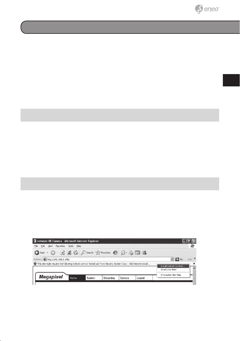
ActiveX-Steuerelement installieren
• Nachdem Sie sich in die Kamera eingeloggt haben, kommt direkt
unter der Adressleiste die Anfrage, ob Sie das ActiveX-Steuerelement installieren möchten.
• Klicken Sie mit der rechten Maustaste auf die Meldung und wählen
Sie “ActiveX-Steuerelement installieren…”, um die Installation des
ActiveX-Steuerelements zuzulassen.
• In der Sicherheitswarnung klicken Sie auf “Installieren”, damit die
DC Viewer Software auf Ihren Computer heruntergeladen wird.
• Drücken Sie auf “Beenden”, um die DC-Viewer-Installation zu been-
den.
RU
RU
9
9
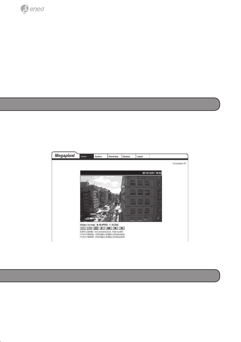
Browser-basierter Viewer
Die Startseite der Dome-Kamera ist wie unten gezeigt. Bitte beachten Sie,
dass die Funktionsknöpfe, abhängig vom Kameramodell, unterschiedlich
sein können.
Weitere Informationen
Das Benutzerhandbuch ist auf der eneo Website unter
www.eneo-security.com oder auf der mitgelieferten CD verfügbar.
1010

Contents
Contents ................................................................................................................. 11
Notes on safety ..................................................................................................... 12
Parts supplied ........................................................................................................ 12
Product description and connections ............................................................... 13
Installation .............................................................................................................. 15
Network setup ........................................................................................................ 16
DE
EN
FR
PL
Power up the Camera ..........................................................................................16
Ethernet Cable Connection..................................................................................16
ActiveX Controls and Plug-ins Settings ...............................................................16
Internet Security Level .........................................................................................17
Accessing the camera ......................................................................................... 17
Login ID & Password ...........................................................................................17
Install the ActiveX control ....................................................................................17
Browser-based viewer .........................................................................................18
Further information .............................................................................................. 19
RU
11
Notes on safety
Please also pay attention to the enclosed safety instructions, and carefully
read through this instruction guide before initial operation.
Important points of advice are marked with a caution symbol.
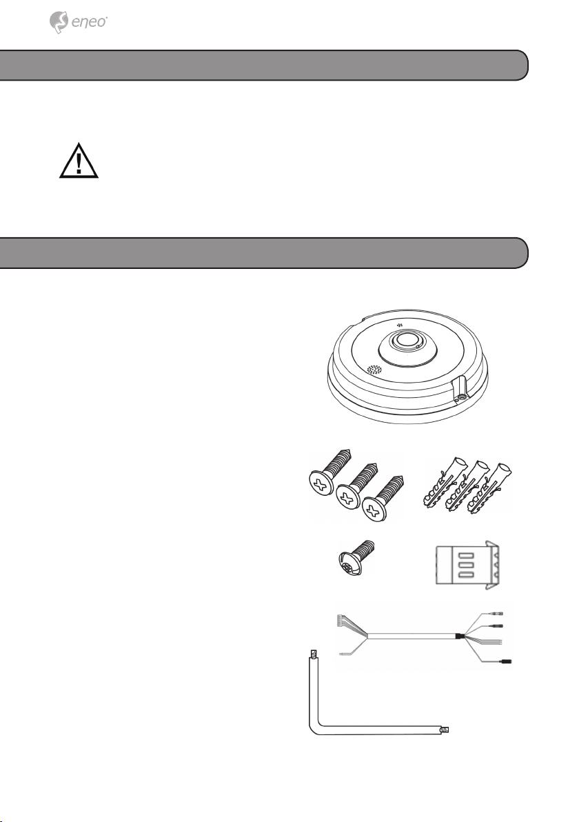
Parts supplied
● 1x Fisheye IP camera
● 1x Installation and operation inst-
ructions
● 1x Torx L-wrench
● 3x Self-tapping screws
● 3x Plastic Anchors
● 1x Security screw
● 1x Power terminal block
● 1x All-in-one cable
● 1x Remote viewer software
12
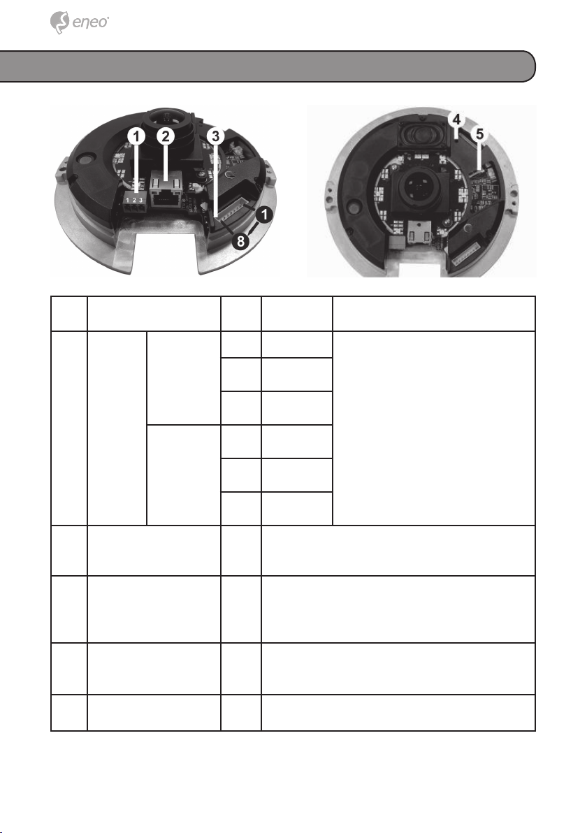
Product description and connections
No. Connector Pin Defi nition Remarks
1 Power* DC 12V 1 Power Power connection
2 Reserved
3 GND
DE
EN
FR
PL
RU
AC 24V 1 Power-1
2 GND
Power-2
2 RJ-45 - 10/100 Mbps Ethernet / PoE (PXD-
5360F01IR)
3 Alarm & Audio I/O* - Please refer to the Alarm & Audio I/O in the
table under Cable Defi nition
4 Reset Button - Restore to default setting; press the button
with a proper tool
5 Micro SD Card Slot - For video recording storage
*All in One Cable is required for Power, Alarm and Audio I/O utilization
13
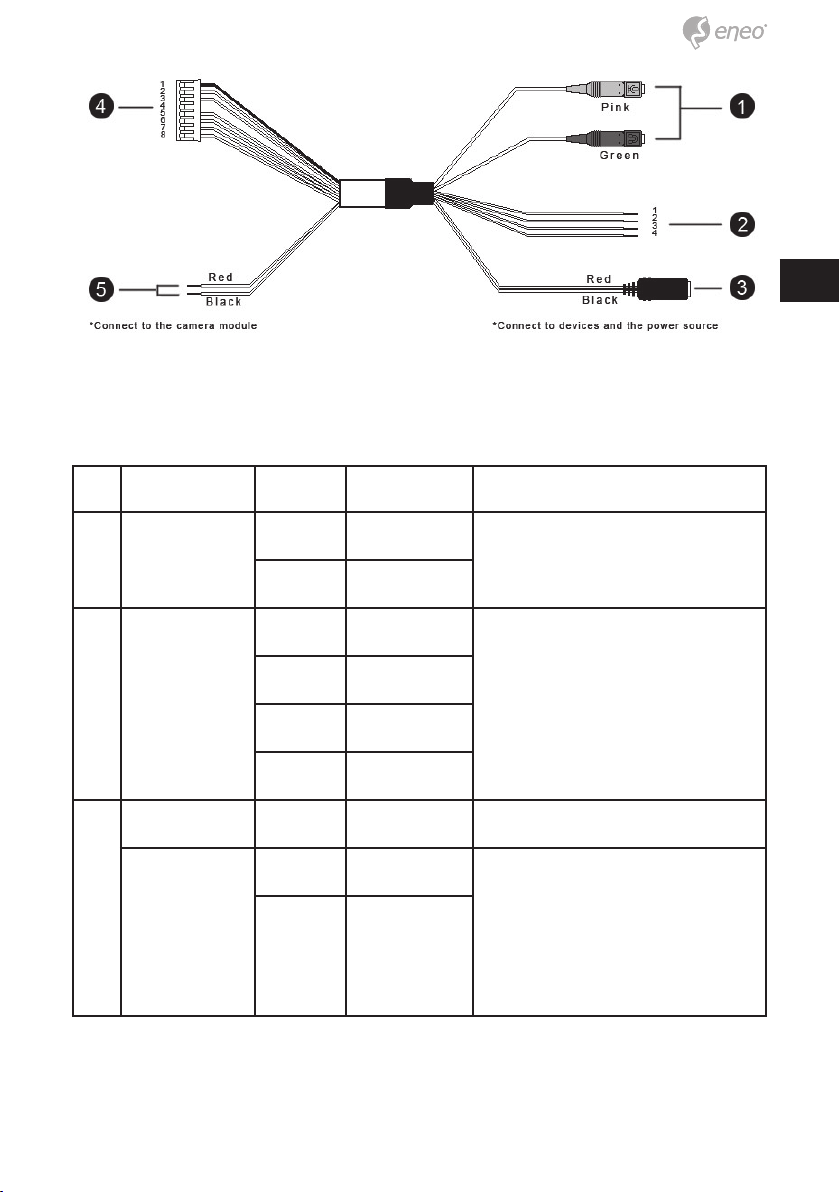
No. Connector Pin Definition Remarks
1 Audio I/O Pink Line In Two-way audio transmission
Green Line Out
2 Alarm (4-Pin
Terminal Block)
3 Power DC Jack - DC 12V Power connection (Tip: +, sleeve:
Power Wires Red AC 24V (+) Remove DC Jack connector
1 ALM_IN – Alarm connection
2 ALM_IN +
3 ALM_OUT –
4 ALM_OUT +
-)
head, and apply AC 24V with
Black AC 24V (–)
Red and Black wires.
Please refer to the section of
Cable Definition in User’s Manual.
14
No. Connector Pin Definition Remarks
4 Alarm & Audio
I/O
5 Power Wires Red DC 12V (+) /
1 GND Two-way audio transmission /
2 Line In
3 Line Out
4 -
5 ALM_IN –
6 ALM_IN +
7 ALM_OUT –
8 ALM_OUT +
AC 24V (+)
Black DC 12V (–) /
AC 24V (–)
Alarm connection
DE
EN
FR
PL
RU
Power connection
Installation
1. Drill two holes in the ceiling or the wall, to match the spacing of the
mounting holes in the base plate.
2. Align the dome base with the previously drilled holes and secure it with
the mounting screws passed through the mounting holes.
3. Fit the cover onto the dome base and tighten the screws with the Torx
wrench.
15

Power up the Camera
To power up the IP Camera, please plug the camera’s DC 12V / AC 24V
cable into the power terminal block. Alternatively, connect the Ethernet
Cable to the camera’s RJ-45 port and plug the other end of the Cable into
a PoE switch.
NOTE: If PoE is used, make sure Power Sourcing Equipment
(PSE) is in use in the network.
Ethernet Cable Connection
Connect one end of the CAT5 Ethernet Cable to the RJ-45 connector of the
IP Camera, and the other end of the cable to the network switch or PC.
NOTE: In some cases, Ethernet Crossover Cable might be needed
when connecting the IP Camera directly to the PC.
NOTE: Check the status of the link indicator and activity indicator
LEDs. If the LEDs are unlit, please check LAN connection.
Green Link Light indicates good network connection.
Orange Activity Light flashes for network activity indication.
Network setup
A client program will be automatically installed on your PC when connecting
to the IP Dome Camera. Before accessing to the IP Dome Camera, please
ensure downloading the ActiveX control is allowed by either changing the
ActiveX controls and plug-ins or setting Internet’s security level to default.
For further details, please refer to the IP Dome Camera’s user manual.
ActiveX Controls and Plug-ins Settings
Step 1: Start the Internet Explorer (IE).
Step 2: Select <Tools> from the main menu of the browser.
Then Click <Internet Options>.
16

Step 3: Click the <Security> tab and select “Internet”, and click <Custom
level> to change ActiveX settings.
Step 4: Set “ActiveX controls and plug-ins” items to <Prompt> or
<Enable>.
Internet Security Level
Step 1: Start the IE.
Step 2: Select <Tools> from the main menu of the browser.
Then Click <Internet Options>.
Step 3: Click the <Security> tab and select “Internet.”
Step 4: Down the page, press “Default Level” and click “OK” to confirm
the setting. Close the browser window, and open a new one later
for accessing the IP Dome Camera
Accessing the camera
The IP Dome Camera’s default IP address is: 192.168.1.10. Therefore, to
access the IP Dome Camera for the first time, set the PC’s IP address as:
192.168.1.XXX; for example:
IP Address: 192.168.1.20
Subnet Mask: 255.255.255.0
Login ID & Password
DE
EN
FR
PL
RU
• Key in the IP Dome Camera’s IP address in the URL bar of the Web
browser window and press “Enter.”
• Enter the default user name (admin) and password (admin) in the
prompt request dialogue. Note that user name is case sensitive.
Install the ActiveX control
• After connecting to the IP Dome Camera, the request for installing
17

the ActiveX control will appear just below the URL bar.
• Right Click on the information bar, and press “Install ActiveX Control…” to permit ActiveX control installation.
• In the pop-up security warning window, click “Install” to start downloading DC Viewer software on the PC.
• Press “Finish” when DC Viewer installation is complete.
Browser-based viewer
The main page of the IP Camera user interface is as shown below. Please
note that the function buttons will vary depending on the camera model.
18

Further information
The Full Manual is available from the eneo web site at
www.eneo-security.com or from the CD supplied with this product.
DE
EN
FR
PL
RU
19

Contenu
Contenu .................................................................................................................. 20
Consignes de sécurité ......................................................................................... 21
Contenu de la livraison ........................................................................................ 21
Description et raccordement du produit...........................................................22
Installation .............................................................................................................. 24
Mise sous tension de la caméra ..........................................................................25
Connexion câble Ethernet ...................................................................................25
Configuration réseau ............................................................................................ 26
Paramètres Contrôles et Plug-ins de ActiveX ......................................................26
Niveau de sécurité Internet ..................................................................................26
Accès à la caméra ................................................................................................ 27
ID de connexion et mot de passe ........................................................................27
Installation du contrôle ActiveX ............................................................................27
Visionneuse Basée sur Navigateur .................................................................. 28
Complément d’information .................................................................................. 28
2020

Consignes de sécurité
Respectez les consignes de sécurité ci-après et lisez attentivement cette
notice avant toute utilisation.
Les remarques importantes sont identifiées par le symbole «
Attention ».
Contenu de la livraison
● 1x Caméra IP Fisheye
● 1x Instructions d’installation et
d’utilisation
● 1x Clé Torx de sécurité
● 3x Vis autotaraudeuses
● 3x Chevilles en plastique
● 1x Vis de sécurité
● 1x Bornier d’alimentation
● 1x Câble tout-en-un
● 1x logiciel de visualisation à
distance
DE
DE
EN
EN
FR
FR
PL
PL
RU
RU
21
21

Description et raccordement du produit
N° Connecteur Bro-
1 Alimen-
tation*
2 RJ-45 - 10/100 Mbps Ethernet / PoE (PXD-
3 E/S alarme et audio* - Voir les E/S alarme et audio dans le tableau
4 Bouton Reset (réiniti-
alisation)
5 Logement Carte
Micro SD
DC 12V 1 Alimentation Branchement électrique
AC 24V 1 Alimentation-1
Défi nition Remarques
che
2 Réservé
3 GND (terre)
2 GND (terre)
Alimentation-2
5360F01IR)
sous Défi nition des câbles
- Restauration du paramétrage par défaut ;
appuyez sur le bouton avec un outil adéquat
- Pour le stockage d’enregistrements vidéo
*Un câble « tout en un » est nécessaire pour l’alimentation et l’utilisation
des E/S alarme et audio.
2222

N° Connecteur Bro-
che
1 Audio E/S Rose Line In Transmission audio bidirection-
Vert Line Out
Définition Remarques
nelle
DE
DE
EN
EN
FR
FR
PL
PL
RU
RU
2 Alarme
(Bornier à 4
broches)
3 Alimentation DC
Jack
Câbles
d’alimentation
1 ALM_IN – Connexion alarme
2 ALM_IN +
3 ALM_OUT –
4 ALM_OUT +
- DC 12V Branchement électrique (Tip: +,
sleeve: -)
Red AC 24V (+) Retirez la tête du connecteur DC
Jack et mettez sous tension AC
Black AC 24V (–)
24 V les câbles rouge et noir.
Consultez la section Définition des câbles du manuel
d’utilisation.
23
23

N° Connecteur Bro-
che
Définition Remarques
4 E/S alarme et
audio
5 Câbles
d’alimentation
Installation
1 GND (terre) Transmission audio bidirection-
nelle / Connexion alarme
2 Line In
3 Line Out
4 -
5 ALM_IN –
6 ALM_IN +
7 ALM_OUT –
8 ALM_OUT +
Rouge DC 12V (+) /
AC 24V (+)
Noir DC 12V (–) /
AC 24V (–)
Branchement électrique
1. Percez deux trous dans le plafond ou le mur, en fonction de
l’espacement des orifices de montage dans le plateau.
2. Alignez l’embase du dôme sur les orifices précédemment forés et fixez-le
à l’aide des vis de montage dans les orifices de montage.
3. Placez le couvercle sur l’embase du dôme et serrez les vis à l’aide de la
Clé Torx.
2424

Mise sous tension de la caméra
Pour mettre la caméra IP sous tension, branchez le câble DC 12 V / AC 24
V sur le bornier d’alimentation. Vous pouvez également brancher le câble
Ethernet sur le port RJ-45 de la caméra et brancher l’autre extrémité du
câble dans un contacteur PoE.
REMARQUE : En cas d’utilisation de la PoE, assurez-vous qu’un
équipement PSE (Power Sourcing Equipment) est utilisé sur le
réseau.
Connexion câble Ethernet
Branchez une extrémité du câble CAT5 Ethernet sur le connecteur RJ-45
de la caméra IP et l’autre extrémité sur le contacteur réseau ou PC.
REMARQUE : Dans certains cas, un câble Ethernet Crossover
peut être nécessaire pour connecter la caméra IP directement sur
le PC.
REMARQUE : Vérifiez le statut des LED de l’indicateur de lien et
de l’indicateur d’activité. Si les LED sont éteintes, vérifiez la connexion LAN.
DE
DE
EN
EN
FR
FR
PL
PL
RU
RU
Le témoin lumineux vert indique une connexion réseau cor
recte.
Le témoin d’activité orange clignote pour signaler une activi
té sur le réseau.
25
25

Configuration réseau
Un programme client sera automatiquement installé sur votre PC lors de
la connexion au réseau de la Caméra dôme IP. Avant de se connecter à la
Caméra Dôme IP, veuillez vérifier que le téléchargement du contrôle ActiveX est permis en changeant les contrôles et les plugins de ActiveX ou en
paramétrant le niveau de sécurité d’Internet sur défaut.
Veuillez consulter le manuel d’utilisateur de la Caméra dôme IP pour un
complément d’information.
Paramètres Contrôles et Plug-ins de ActiveX
Étape 1: démarrer Internet Explorer (IE).
Étape 2: sélectionner <Outils> dans le menu principal du navigateur. Puis
cliquer sur <Options Internet>.
Étape 3: cliquer sur l’onglet <Sécurité> et sélectionner « Internet », et cli-
quer sur <Niveau personnalisé> pour changer les paramètres de
ActiveX.
Étape 4: établir les éléments « contrôles et plug-ins ActiveX » sur <Deman-
der> ou <Activer>.
Niveau de sécurité Internet
Étape 1: démarrer IE.
Étape 2: sélectionner <Outils> dans le menu principal du navigateur. Puis
cliquer sur <Options Internet>.
Étape 3: cliquer sur l’onglet <Sécurité> et sélectionner « Internet.
Étape 4: en bas de la page, presser « Niveau par Défaut » et cliquer sur
<OK> pour confirmer la configuration. Fermer la fenêtre du navigateur, et en ouvrir une nouvelle plus tard pour accéder à la Caméra
IP.
2626

Accès à la caméra
L’adresse IP par défaut de la Caméra Dôme est : 192.168.1.10. Pour un
premier accès à la caméra, veuillez donc paramétrer l’adresse IP du PC
comme suit: 192.168.1.XXX. Exemple:
Adresse IP : 192.168.1.20
Masque de sous-réseau : 255.255.255.0
ID de connexion et mot de passe
• Saisissez l’adresse IP de la caméra dôme IP dans la barre
d’adresse du navigateur et appuyez sur « Entrée
• Saisissez le nom d’utilisateur par défaut (admin) et le mot de passe
(admin) dans la fenêtre correspondante. Le nom d’utilisateur est sensible à
la casse.
Installation du contrôle ActiveX
• Une fois connecté à la Caméra Dôme IP de réseau, une demande
d’installation du contrôle ActiveX control apparaîtra sous la barre
d’adresse.
• Faites un clic droit sur la barre d’information, et cliquez sur « Installer le Contrôle ActiveX » pour autoriser l’installation de contrôle
ActiveX.
DE
DE
EN
EN
FR
FR
PL
PL
RU
RU
• Cliquer sur « Installer » dans la fenêtre de sécurité qui s’affiche,
pour commencer à télécharger le logiciel de visualisation DC Viewer sur le
PC.
• Cliquer sur « Finir » une fois l’installation de DC Viewer terminée.
27
27

Visionneuse Basée sur Navigateur
La page principale de l’interface de l’utilisateur de la Caméra IP est telle
que présentée ci-dessous. Veuillez noter que les boutons de fonction changeront en fonction du modèle de la caméra.
Complément d’information
Le manuel complet est proposé sur le site Web d’eneo
- www.eneo-security.com - ou sur le CD accompagnant ce produit.
2828

Spis treści
Spis treści ............................................................................................................... 29
Wskazówki dotyczące bezpieczeństwa ............................................................ 30
Elementy wchodzące w skład dostawy ............................................................ 30
Opis produktu i podłączenia ............................................................................... 31
Instrukcja instalacji ................................................................................................33
Zasilanie kamery .................................................................................................34
Podłączenie kabla Ethernet .................................................................................34
Konfiguracja sieci ................................................................................................ 35
Ustawienia kontrolek i wtyczek ActiveX ...............................................................35
Poziom bezpieczeństwa Internetu .......................................................................35
Dostęp do kamery ................................................................................................ 36
Nazwa użytkownika i hasło ..................................................................................36
Instalacja formantu ActiveX .................................................................................36
Oprogramowanie do przeglądania ...................................................................37
działające w przeglądarce internetowej ........................................................... 37
DE
DE
EN
EN
FR
FR
PL
PL
RU
RU
Informacje dodatkowe ........................................................................................ 37
29
29

Wskazówki dotyczące bezpieczeństwa
Prosimy przestrzegać także załączonych wskazówek dotyczących
bezpieczeństwa i dokładnie przeczytać niniejszą instrukcję obsługi przed
uruchomieniem urządzenia.
Ważne wskazówki są oznaczone symbolem UWAGA.
Elementy wchodzące w skład dostawy
● 1x Kamera IP Fisheye
● 1x Instrukcja instalacji i obsługi
● 1x Klucz zabezpieczający Torx
● 3x Wkręty samogwintujące
● 3x Plastikowe mocowania
● 1x Śruba zabezpieczająca
● 1x Listwa zaciskowa zasilania
● 1x Kabel uniwersalny
● 1x oprogramowanie do zdalnego
przeglądania
3030

Opis produktu i podłączenia
Nr Złącze Styk Defi nicja Uwagi
1 Zasila-
nie*
12 V
prądu
stałego
1 Zasilanie Złącze zasilania
2 Zastrzeżone
3 GND
DE
DE
EN
EN
FR
FR
PL
PL
RU
RU
24 V
prądu
przemiennego
2 RJ-45 - 10/100 Mbps Ethernet / PoE (PXD-
3 Złącze WE/WY alar-
mu i dźwięku*
4 Przycisk zerowania - Przywracanie wartości domyślnych; naciśnij
5 Gniazdo karty mi-
croSD
*Do podłączenia zasilania i złącza WE/WY alarmu i dźwięku wymagany jest
kabel uniwersalny
1 Zasilanie-1
2 GND
Zasilanie-2
5360F01IR)
- Patrz złącze WE/WY alarmu i dźwięku w sekcji Defi nicja kabla w tabeli
przycisk odpowiednim narzędziem
- Służy do przechowywania nagrań
31
31

Nr. Złącze Styk Definicja Uwagi
1 Złącze WE/WY
dźwięku
2 Alarm
(Złącze 4-stykowe)
3 Złącze prądu
stałego
Przewody zasilania
Różowy Złącze
wejściowe
Zielony Wyjście liniowe
1 ALM_IN – Złącze alarmu
2 ALM_IN +
3 ALM_OUT –
4 ALM_OUT +
- 12 V prądu
stałego
Czerwo-ny24 V (+) prądu
przemiennego
Czarny 24 V (–) prądu
przemiennego
Dwukierunkowa komunikacja
dźwiękowa
Złącze zasilania (Tip: +,
sleeve: -)
Usuń zatyczkę złącza prądu
stałego i przyłóż napięcie 24
V prądu przemiennego na
czerwony i czarny przewód.
Przejdź do sekcji Definicja kabla w Podręczniku
użytkownika.
3232

Nr. Złącze Styk Definicja Uwagi
4 Złącze WE/WY
alarmu i dźwięku
5 Przewody zasi-
lania
1 GND Dwukierunkowa komunikacja
dźwiękowa / Złącze alarmu
2 Złącze
wejściowe
3 Wyjście liniowe
4 -
5 ALM_IN –
6 ALM_IN +
7 ALM_OUT –
8 ALM_OUT +
Czerwo-ny12 V (+) prądu
stałego / 24 V
(+) prądu przemiennego
Czarny 12 V (–) prądu
stałego / 24 V
(–) prądu przemiennego
Złącze zasilania
DE
DE
EN
EN
FR
FR
PL
PL
RU
RU
Instrukcja instalacji
1. Wywierć dwa otwory w suficie lub ścianie, tak aby dopasować odstęp
dwóch otworów montażowych w płytce bazowej.
2. Wyrównaj podstawę kopuły z wywierconymi wcześniej otworami i zabezpiecz ją śrubami montażowymi przeprowadzonymi przez otwory montażowe.
3. Załóż pokrywę na podstawę kopuły i dokręć śruby kluczem imbusowym.
33
33

Zasilanie kamery
Aby włączyć zasilanie kamery IP, podłącz kabel 12 V prądu stałego / 24
V prądu przemiennego do listew zaciskowych zasilania. Można również
podłączyć kabel Ethernet do portu RJ-45 kamery, a drugi jego koniec
podłączyć do przełącznika PoE.
UWAGA: W przypadku korzystania z zasilania PoE należy się
upewnić, że w sieci jest używane urządzenie typu Power Sourcing
Equipment (PSE).
Podłączenie kabla Ethernet
Podłącz jeden koniec kabla Ethernet CAT5 do złącza RJ-45 kamery IP, a
drugi jego koniec do przełącznika sieciowego lub komputera.
UWAGA: Podczas podłączania kamery IP bezpośrednio do
komputera w niektórych przypadkach konieczne może być użycie
kabla krzyżowego Ethernet.
.
UWAGA: Należy sprawdzić stan diod LED wskaźnika połączenia i
wskaźnika transmisji danych. Jeśli diody LED się nie świecą,
należy sprawdzić połączenie LAN.
3434
Zielona dioda połączenia informuje o dobrym połączeniu sieciowym.
Pomarańczowa dioda połączenia miga w trakcie transmisji danych w sieci.

Konfiguracja sieci
Oprogramowane klienta zostanie automatycznie zainstalowane na komputerze po podłączeniu do kamery kopułowej IP. Przed uzyskaniem dostępu
do kamery kopułowej IP upewnij się, że możliwe jest pobranie formantu
ActiveX poprzez zmianę ustawień kontrolek i wtyczek ActiveX lub przez
ustawienie poziomu bezpieczeństwa Internetu na domyślny.
Więcej instrukcji na ten temat zawiera podręcznik użytkownika kamery
kopułowej IP.
Ustawienia kontrolek i wtyczek ActiveX
DE
DE
EN
EN
FR
FR
PL
PL
Krok 1: Uruchom przeglądarkę Internet Explorer (IE).
Krok 2: Z głównego menu przeglądarki wybierz opcję <Narzędzia>. Kliknij
pozycję <Opcje internetowe>.
Krok 3: Aby zmienić ustawienia ActiveX, kliknij kartę <Zabezpieczenia> i
wybierz pozycję „Internet”, a następnie kliknij przycisk <Poziom
niestandardowy>.
Krok 4: Ustaw opcję „Formanty ActiveX i dodatki plug-in” na <Monituj> lub
<Włącz>.
Poziom bezpieczeństwa Internetu
Krok 1: Uruchom przeglądarkę Internet Explorer (IE).
Krok 2: Z głównego menu przeglądarki wybierz opcję <Narzędzia>. Kliknij
pozycję <Opcje internetowe>.
Krok 3: Kliknij kartę <Zabezpieczenia> i wybierz pozycję „Internet.”
Krok 4: W dolnej części strony naciśnij przycisk „Poziom domyślny” i
kliknij przycisk „OK” w celu potwierdzenia ustawienia. Zamknij
okno przeglądarki i otwórz nowe, aby uzyskać dostęp do kamery
kopułowej IP.
RU
RU
35
35

Dostęp do kamery
Domyślny adres IP kamery kopułowej IP jest następujący: 192.168.1.10.
Aby za pierwszym razem uzyskać dostęp do kamery kopułowej IP, należy
ustawić adres IP komputera w postaci: 192.168.1.XXX; na przykład:
Adres IP: 192.168.1.20
Maska podsieci: 255.255.255.0
Nazwa użytkownika i hasło
• W pasku adresu, znajdującym się w oknie przeglądarki internetowej,
należy wprowadzić adres IP kamery kopułowej IP i nacisnąć klawisz
„Enter”.
• W wyświetlonym oknie dialogowym należy wprowadzić domyślną
nazwę użytkownika (admin) i hasło (admin). Należy pamiętać, że w
nazwie użytkownika jest rozróżniana wielkość liter.
Instalacja formantu ActiveX
• Po połączeniu z kamerą kopułową IP pod paskiem adresu
przeglądarki internetowej zostanie wyświetlony monit dotyczący
instalacji formantu ActiveX.
• Prawym przyciskiem myszy kliknij pasek informacyjny i naciśnij
przycisk „Zainstaluj formant ActiveX…” w celu umożliwienia instalacji
formantu ActiveX.
• W wyskakującym oknie ostrzegawczym kliknij polecenie „Zainstaluj”, aby rozpocząć pobieranie oprogramowania DC Viewer na
komputer.
• Po zakończeniu instalacji oprogramowania DC Viewer naciśnij przy
cisk „Zakończ”.
3636

Oprogramowanie do przeglądania
działające w przeglądarce internetowej
Poniżej przedstawiono główną stronę interfejsu użytkownika kamery IP.
Należy pamiętać, że przyciski funkcyjne mogą się różnić w zależności od
modelu kamery.
DE
DE
EN
EN
FR
FR
PL
PL
RU
RU
Informacje dodatkowe
Pełna instrukcja obsługi jest dostępna na stronie internetowej eneo pod
adresem www.eneo-security.com lub na płycie CD dostarczonej w zestawie
z tym urządzeniem.
37
37

Содержание
Содержание .......................................................................................................... 38
Замечания по безопасности ............................................................................ 39
Объем поставки ................................................................................................... 39
Описание изделия и присоединения ............................................................. 40
Монтаж ................................................................................................................... 42
Включение питания камеры ..............................................................................43
Подключение кабеля Ethernet...........................................................................43
Сетевая настройка ............................................................................................. 44
Настройки ActiveX и плагинов ...........................................................................44
Internet Security Level (уровень безопасности интернет) ................................44
Доступ к камере .................................................................................................. 45
Логин и пароль: ..................................................................................................45
Установите управление ActiveX ........................................................................45
Обзор на основе браузера .............................................................................. 46
Дополнительная информация ......................................................................... 46
3838

Замечания по безопасности
Обратите, пожалуйста, внимание на прилагаемые указания по
безопасности и внимательно прочитайте это руководство перед
началом работы.
Важные рекомендации отмечены символом предостережения.
Объем поставки
● 1x Камера Fisheye IP
● 1x инструкция по монтажу и
эксплуатации
● 1x Защитный звездообразный
ключ
● 3x Самонарезающие винты
● 3x Пластиковые анкера
● 1x Защитный винт
● 1x Силовая терминальная
колодка
● 1x Универсальный кабель
● 1x Программное обеспечение
дистанционного наблюдения
DE
DE
EN
EN
FR
FR
PL
PL
RU
RU
39
39

Описание изделия и присоединения
№. Коннектор Штифт Описание Примечания
1 Питание* 12В
пост.
тока
24В
перем.
тока
2 RJ-45 - 10/100 МБ/сек Ethernet / Питание по Ether-
3 Ввод/вывод
сигналов и звука*
4 Кнопка сброса - Восстановление настроек по
5 Разъем для
микро SD-карты
1 Питание Подключение питания
2 Резервный
3 Заземление
1 Питание-1
2 Заземление
Питание-2
net (PXD-5360F01IR)
- Пожалуйста, смотрите ввод/вывод сигналов
и звука в таблице под описанием кабеля
умолчанию; нажмите кнопку с помощью
соответствующего инструмента
- Для сохранения записанного видео
*Требуется универсальный кабель для использования ввода/вывода
питания, сигналов и звука
4040

№. Коннектор Штифт Описание Примечания
1 Ввод/вывод
звука
Розовый Линия
подключена
Зеленый Линия
отключена
Двухсторонняя передача
звука
DE
DE
EN
EN
FR
FR
PL
PL
RU
RU
2 Сигнал
(4-штифтовая
КЛЕММНАЯ
колодка)
3 Разъем питания
пост. тока
Силовые
провода
1 СИГН_ВКЛ – Подключение сигнала
2 СИГН_ВКЛ +
3 СИГН_ВЫКЛ
–
4 СИГН_ВЫКЛ
+
- 12В пост.
тока
Красный 24В перем.
тока (+)
Черный 24В перем.
тока (–)
Подключение питания (Tip: +,
sleeve: -)
Снимите наконечник
коннектора разъема пост.
тока и подсоедините 24В
перем. тока с помощью
красного и черного
проводов.
Пожалуйста, смотрите
раздел Обозначение кабеля
в Руководстве пользователя
41
41

№. Коннектор Штифт Описание Примечания
4 Ввод/вывод
сигналов и
звука
5 Силовые
провода
1 Заземление Двухсторонняя передача
звука / Подключение сигнала
2 Линия
подключена
3 Линия
отключена
4 -
5 СИГН_ВКЛ
–
6 СИГН_ВКЛ
+
7 СИГН_ВЫКЛ
–
8 СИГН_ВЫКЛ
+
Красный 12В пост.
тока (+) /
24В перем.
тока (+)
Подключение питания
Черный 12В пост.
тока (–) /
24В перем.
тока (–)
Монтаж
1. Просверлите в потолке или в стене два отверстия, соответствующие
посадочным отверстиям пластины основания.
2. Совместите основание купола и ранее просверленные отверстия
и закрепите купол монтажными винтами, пропущенными сквозь
4242

монтажные отверстия.
3. Установите крышку на основание купола и затяните винты угловым
торцовым ключом.
Включение питания камеры
Чтобы включить питание камеры, пожалуйста, подключите кабель 12В
пост. тока / 24В перем. тока камеры к силовой клеммной коробке.
Либо подключите кабель Ethernet к порту RJ-45 камеры и соедините
другой конец кабеля с переключателем питания по Ethernet.
ПРИМЕЧАНИЕ: Если используется питание по Ethernet,
убедитесь, что оборудование источника питания (ОИП)
используется в сети.
Подключение кабеля Ethernet
Подключите один конец кабеля Ethernet CAT5 к соединителю RJ-45
камеры IP, а другой конец кабеля – к сетевому переключателю или ПК.
ПРИМЕЧАНИЕ: В некоторых случаях, при подключении камеры
IP непосредственно к ПК, может потребоваться кабель Ethernet Crossover.
DE
DE
EN
EN
FR
FR
PL
PL
RU
RU
ПРИМЕЧАНИЕ: Проверьте состояние светодиодов
индикатора подключения и функционирования. Если
светодиоды не горят, пожалуйста, проверьте подключение
LAN.
Зеленый индикатор подключения означает хорошее соединение с
сетью.
Оранжевый индикатор функционирования мигает для индикации
действия сети.
43
43

Сетевая настройка
При подключении купольной IP-видеокамеры на вашем ПК
автоматически установится клиентское программное обеспечение.
Перед обращением к купольной IP-видеокамере убедитесь в том,
что загрузка ActiveX разрешена либо изменением установок ActiveX и плагинов, либо установкой уровня безопасности интернета по
умолчанию.
Подробные сведения приводятся в руководстве пользователя
купольной IP-видеокамеры.
Настройки ActiveX и плагинов
Шаг 1: Запустите интернет-браузер (IE).
Шаг 2: Выберите пункт <Tools> (инструменты) главного меню
браузера. Затем щелкните по пункту <Internet Options> (опции
интернет).
Шаг 3: Щелкните по закладке <Security> (безопасность), выберите
пункт «Internet» и щелкните по пункту <Custom level>
(произвольный уровень), чтобы изменить настройки ActiveX.
Шаг 4: Задайте вариант <Prompt> (напоминать) или <Enable>
(разрешить) для «ActiveX controls and plug-ins» (управление и
плагины Active).
Internet Security Level (уровень безопасности интернет)
Шаг 1: Запустите интернет-браузер (IE).
Шаг 2: Выберите пункт <Tools> (инструменты) главного меню
браузера.Затем щелкните по пункту <Internet Options> (опции
интернет).
Шаг 3: Щелкните по закладке <Security> (безопасность) и выберите
«Internet».
Шаг 4: Внизу страницы нажмите пункт «Default Level» (уровень
по умолчанию) и щелкните кнопку ОК, чтобы подтвердить
произведенную настройку. Закройте окно браузера и
откройте новое окно, чтоб получить доступ к купольной IPвидеокамере.
4444

Доступ к камере
IP-адрес купольной видеокамеры по умолчанию: 192.168.1.10. Поэтому,
для первоначального доступа к купольной IP-видеокамере, задайте
следующий IP-адрес компьютера: 192.168.1.XXX; например:
IP-адрес: 192.168.1.20
Маска подсети: 255.255.255.0
Логин и пароль:
• Введите IP-адрес купольной видеокамеры в строку URL
браузера и нажмите клавишу «Enter».
• Введите имя пользователя по умолчанию (admin) и пароль (ad-
min) в диалоговое окно подсказки. Имейте в виду зависимость имени
пользователя от регистра.
Установите управление ActiveX
• После подключения купольной IP-видеокамеры
непосредственно под строкой URL появится запрос на
установку управления ActiveX.
• Щелкните правой кнопкой мыши по информационной панели и
нажмите «Install ActiveX Control…» (установить управление ActiveX).
DE
DE
EN
EN
FR
FR
PL
PL
RU
RU
• Во всплывающем окне предупреждения о безопасности
щелкните пункт «Install» (установить), чтобы начать загрузку на
компьютер программного обеспечения DC Viewer (вывод изображения
купольной видеокамеры).
• Нажмите кнопку «Finish» (завершить) по завершению установки
DC Viewer..
45
45

Обзор на основе браузера
Главная страница пользовательского интерфейса IP-видеокамеры
показана ниже. Имейте в виду различие функциональных кнопок для
разных моделей видеокамеры.
Дополнительная информация
Полное руководство доступно на веб-сайте компании «eneo» www.eneosecurity.com или на CD, поставляемым с этим изделием.
4646

DE
DE
EN
EN
FR
FR
PL
PL
RU
RU
47
47

eneo® is a registered trademark of
Videor E. Hartig GmbH
Exclusive distribution through specialised trade channels only.
Videor E. Hartig GmbH
Carl-Zeiss-Straße 8 · 63322 Rödermark/Germany
Tel. +49 (0) 6074 / 888-0 · Fax +49
(0) 6074 / 888-100
www.videor.com
www.eneo-security.com
Technical changes reserved
© Copyright by Videor E. Hartig
GmbH 01/2013
 Loading...