

Eneo MMX Instruction Manual
1
Instruction Manual
MMX
Network Controlled Video Matrix System

2
Contents
1. Safety Instructions / Maintenance .......................................................................................................................3
2. Introduction ........................................................................................................................................................
4
2.1 Product Overview .....................................................................................................................................4
2.2 Main Features ..........................................................................................................................................4
2.3 Typical Applications ..................................................................................................................................5
3. Installation..........................................................................................................................................................8
3.1 Front Panel ...............................................................................................................................................8
3.2 Rear Panel ...............................................................................................................................................8
4. Case Installation ...............................................................................................................................................
13
4.1 Medium-Sized System (without DVRs) ....................................................................................................14
4.2 Medium-Sized System (with DVRs) ......................................................................................................... 19
4.3 Enterprise-Sized System (with DVRs) ......................................................................................................25
5. Monitor Layout and Control ...............................................................................................................................
33
5.1 Main Monitor ..........................................................................................................................................33
5.2 Quad Monitor ..........................................................................................................................................39
5.3 Spot Monitor ...........................................................................................................................................42
5.4 Spot MMX Monitor ..................................................................................................................................44
6. Configuration ....................................................................................................................................................47
6.1 System ...................................................................................................................................................48
6.2 Network .................................................................................................................................................51
6.3 Video ......................................................................................................................................................55
6.4 Event ......................................................................................................................................................62
7. Troubleshooting ................................................................................................................................................66
8. Specifications ...................................................................................................................................................67
Appendix 1 – Connector Pin Outs ............................................................................................................................
69
Appendix 2 – MMX ID Switch Settings ....................................................................................................................
70
Appendix 3 – Spot MMX Cable Connection ..............................................................................................................71
Appendix 4 – Map of Screens (Remote Setup) ........................................................................................................
77
Betriebsanleitung
Installation and Operating Instructions
Mode d’emploi
Instrucciones de manejo
www.videor.com
⇒

3
1. Safety Instructions / Maintenance
• Read these safety instructions and the operation manual first before you install and commission the unit.
• Keep the manual in a safe place for later reference.
• The system may only be commissioned and maintained by personnel authorized to do this and it must only be
carried out in accordance with relevant standards and guidelines.
• Never cover the ventilation slots to avoid overheating.
• Never insert metal objects or any other items into the vents. This may permanently damage the unit.
• Protect your unit from contamination with water and humidity to prevent it from permanent damage.
Never switch the unit on when it gets wet.
Have it checked at an authorized service center in this case.
• Never operate the units outside of the specifications as this may prevent their functioning.
• Do not operate the unit beyond their specified temperature, humidity or power ratings.
Operate the unit only at a temperature range of 0°C to +40°C and at a humidity of max. 80%.
• The unit should be protected against excessive heat, dust, damp and vibration.
• Do not place any heavy objects on the unit.
• To disconnect the power cord of the unit, pull it out by the plug. Never pull the cord itself.
• Pay attention when laying the connection cable and observe that the cable is not subject to heavy loads, kinks, or
damage and no moisture can get in.
Do not attempt to disassemble the camera board from the dome.
• Contact your local dealer in case of malfunction.
• The connection cable should only be changed by Videor E. Hartig GmbH.
• The warranty becomes void if repairs are undertaken by unauthorized persons. Do not open the housing.
• Installation, maintenance and repair have to be carried out only by authorized service centers.
Before opening the cover disconnect the unit from mains input.
• Only use original parts and original accessories from Videor E. Hartig GmbH.
• Do not use strong or abrasive detergents when cleaning the dome. Use a dry cloth to clean the dome surface.
In case the dirt is hard to remove, use a mild detergent and wipe gently.
NOTE: This is a class A digital device.
This digital device can cause harmful interference in a residential area; in this case the user may be
required to take appropriate corrective action at his/her own expense.

4
2. Introduction
2.1 Product Overview
MMX, the new generation of matrix systems designed by eneo, combines matrix, quad and multiplexer all in one
device. The multifunctional „3-in-1 matrix system” targets the needs of small and medium-sized control centers and
features a variety of flexible applications. If the system, for example, requires a digital record, one can be integrated
into and managed by the MMX. A high degree of user-friendliness, simplified installation as well as excellent cost/
performance ratio are other benefits.
Perfect for medium-sized applications. While it usually takes a considerable amount of effort to extend or adjust a
common matrix, the MMX system consists of a system block that may be programmed optionally as Master, Slave or
spot unit. This allows for trouble-free and cost-effective extension of existing systems. Due to its arbitrarily scalable
structure, the MMX by eneo provides many additional functions including motion and video loss detection, alarm out
control or email notification of events.
These may be easily configured via a network with the user-friendly installation program. The intuitive user guidance
allows anyone with knowledge of Windows to setup the MMX by means of a few clicks. The MMX is based on a
Master MMX and any number of MMX Slaves. It is only necessary to configure one Master, since it keeps all
information and controls the Slaves.
Customized layout. The combination of multiple MMX devices will create a matrix system of 16 to 256 cameras. Each
of these cameras transmits live images and, if recorders are connected, recordings that may be accessed separately.
Every matrix block contains four quad outputs each. The connected monitors may be used for both event monitoring
and permanent monitoring. Unlike standard matrix devices, the MMX features a main output that can play a variety of
pictures simultaneously and display them in a customized layout. Up to ten different layouts may be customized and
selected with the help of the keyboard. The KBD-NSC-100 by eneo is a keyboard that matches the MMX perfectly.
Both devices combined are the ideal basis for a matrix system that can be installed easily and offers a number of
options for expansion.
2.2 Main Features
• Multi Functional Network Matrix System
• MMX replaces 3 Devices (Matrix, Quad, Multiplexer)
• Optimal Solution for Medium Sized Control Centers
• Unlimited User Expandability (MMX Master & Slaves)
• MMX covers any Size by its Scalable Structure
• Provides Multiple Video Images & 4 Quad Outputs
• Fully Networked Environment with MMX & KBD-NSC-100
• Intuitive Monitor Setup
• Configuration of Master MMX only
• Motion, Alarm and Video Loss Detection
• Event Notification by e-mail and more
• Easy Installation and Expanding
Parts supplied:
• Network controlled Video Matrix System
• 19” Rack mount kit
• Mains cable
• CD ROM (INIT S/W)
• Instruction manual
5
2.3 Typical Applications
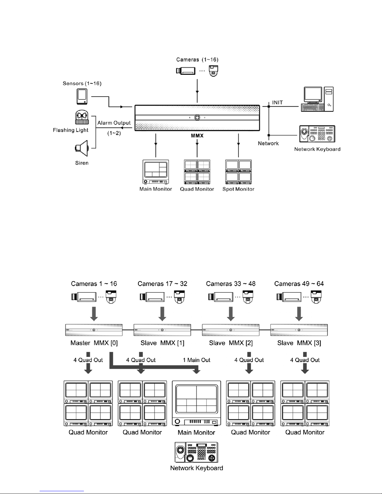
Medium-Sized System (without DVRs)
NOTE: The MMX is controlled by a network keyboard via Ethernet.
Refer to the user’s manual of network keyboard on instructions for using the network keyboard.

6
• Multiple cameras can be connected directly to the MMXs for live monitoring.
• Video from any cameras is displayed in the main monitor of a master MMX in the user-defined layouts
(max. 16-channel layout), and you can change the layout by using a network keyboard at any time.
• Video from cameras connected to a MMX is displayed on the quad monitor of the MMX in the quad- or single screen layout.
• Video from cameras connected to a MMX is displayed on the spot monitor of the MMX in the single- screen layout.
• Sequence monitoring or event monitoring will be available according to the preset setting on each monitor.
• Refer to
Chapter 4 – Case Installation, 4.1 Medium-Sized System (without DVRs) for details on the installation
and configuration of the medium-sized system without DVRs.
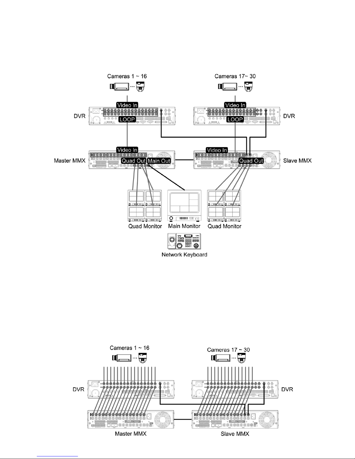
Medium-Sized System (with DVRs)
• You can monitor video from cameras connected to the MMX through Loop Out ports of DVRs.
You can control DVRs if Main Outs of the DVRs are connected to the master MMX.
• Video from any cameras is displayed in the main monitor of a master MMX in the user-defined layouts
(max. 16-channel layout), and you can change the layout by using a network keyboard at any time.
• Video from cameras of a DVR connected to a MMX is displayed on the quad monitor of the MMX in the quad- or
single-screen layout.
• Video from cameras of a DVR connected to a MMX is displayed on the spot monitor of the MMX in the single screen layout.
• Sequence monitoring or event monitoring will be available according to the preset setting on each monitor.
• Refer to
Chapter 4 – Case Installation, 4.2 Medium-Sized System (with DVRs) for details on the installation
and configuration of the medium-sized system with DVRs.
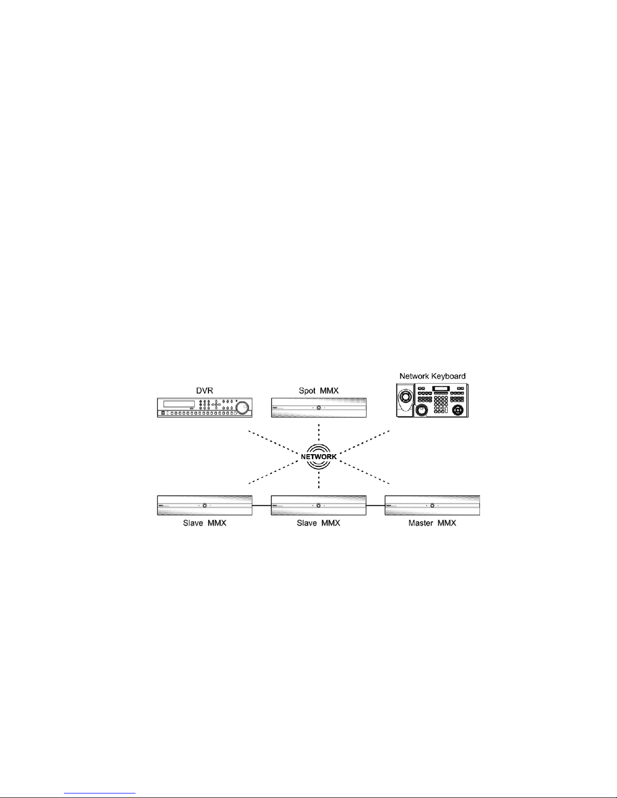
7
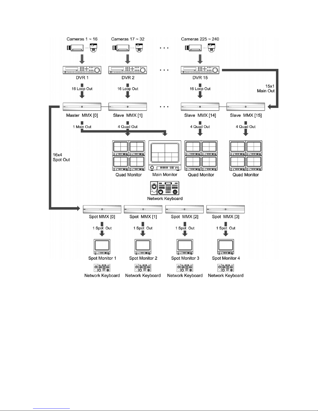
• You can monitor video from cameras connected to the MMX through Loop Out ports of DVRs. You can control DVRs
if Main Outs of the DVRs are connected to the master MMX. Spot MMXs allow you to monitor video from the
maximum 240 cameras and control DVRs on the spot MMX monitors connected to the spot MMXs.
• Video from any cameras is displayed in the main monitor of a master MMX in the user-defined layouts
(max. 16-channel layout), and you can change the layout by using a network keyboard at any time.
• Video from any cameras is displayed on the spot MMX monitors connected to the spot MMXs in the single screen
layout, and you can change the monitoring channel by using a network keyboard at any time.
• Video from cameras of a DVR connected to a MMX is displayed on the quad monitor of the MMX in the quad- or
single-screen layout.
• Video from cameras of a DVR connected to a MMX is displayed on the spot monitor of the MMX in the single-
screen layout.
• Sequence monitoring or event monitoring will be available according to the preset setting on each monitor.
• Refer to
Chapter 4 – Case Installation, 4.3 Enterprise-Sized System (with DVRs) for details on the installation
and configuration of the enterprise-sized system with DVRs.
Enterprise-Sized System (with DVRs)
8
3. Installation
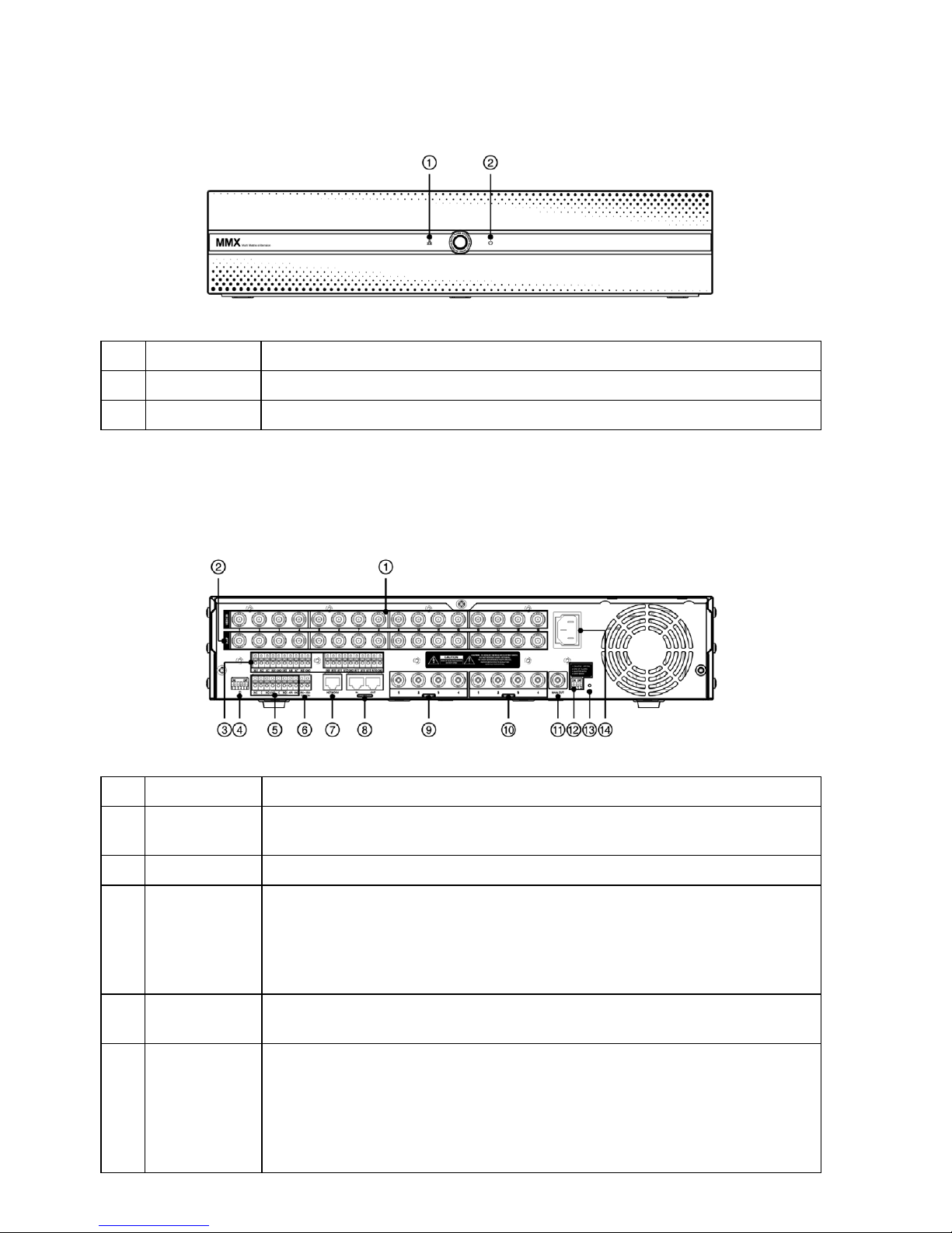
3.1 Front Panel
No. Designation Details
1 Network LED The LED is lit when the unit is connected to a network via Ethernet.
2 Power LED The LED is lit when the unit is on.
3.2 Rear Panel
No. Designation Details
1 Video In Connect coaxial cables to the MMX from the video sources (NTSC or PAL). Cameras can
be connected to the MMX directly or through loop out or main out ports of DVRs.
2 Loop Connect coaxial cables to connect the video source of the MMX to another device.
3 Alarm In Connect alarm-in devices. Connect the ground side of the alarm inputs to the GND
connector. Mechanical or electrical switches can be wired to the AI (Alarm-In) and GND
(Ground) connectors. The voltage range of the alarm input is from 0V to 5V. The threshold
voltage of electrical switches for NC (Normally Close) is above 2.4V and for NO (Normally
Open) is below 0.3V, and should be stable at least 0.5 seconds to be detected.
4 MMX ID Switch Configure the MMX ID. Every MMX should have its own unique ID.
Refer to MMX ID Switch for details on MMX ID switch setting.
5 Alarm Output/
Alarm Reset In
Connect an alarm-out device to the NC (Normally Closed) and C (Common) connectors
or the NO (Normally Open) and C (Common) connectors. NC/NO is a relay output which
sinks 2A at 125VAC and 1A at 30VDC. An external signal to the Alarm Reset In can be
used to reset the Alarm Out signal. Mechanical or electrical switches can be wired to the
ARI (Alarm Reset In) and GND (Ground) connectors. The threshold voltage is below 0.3V
and should be stable at least 0.5 seconds to be detected.

9
No. Designation Details
6 RS485 Connect a PTZ camera to control a PTZ camera.
7 Network Connect a UTP Cat5 cable with an RJ-45 jack. Refer to the Chapter 6 – Configuration,
6.2 Network, IP Address for details on network setup.
8 Daisy Chain
In/Out
Connect the STP Cat5E cable with an RJ-45 jack to daisy-chain slave MMXs (Out) and a
master MMX (In). See below for more details.
9 Spot Out Connect a spot monitor (NTSC or PAL) for monitoring video in single-screen layout.
The cable connection might be different depending on the MMX’s operation mode.
Refer to Chapter 4 – Case Installation for details.
10 Quad Out Connect a quad monitor (NTSC or PAL) for monitoring video in quad- or single- screen
layout.
11 Main Out Connect a main monitor (NTSC or PAL) for monitoring video in various screen layouts
(A Master MMX Only).
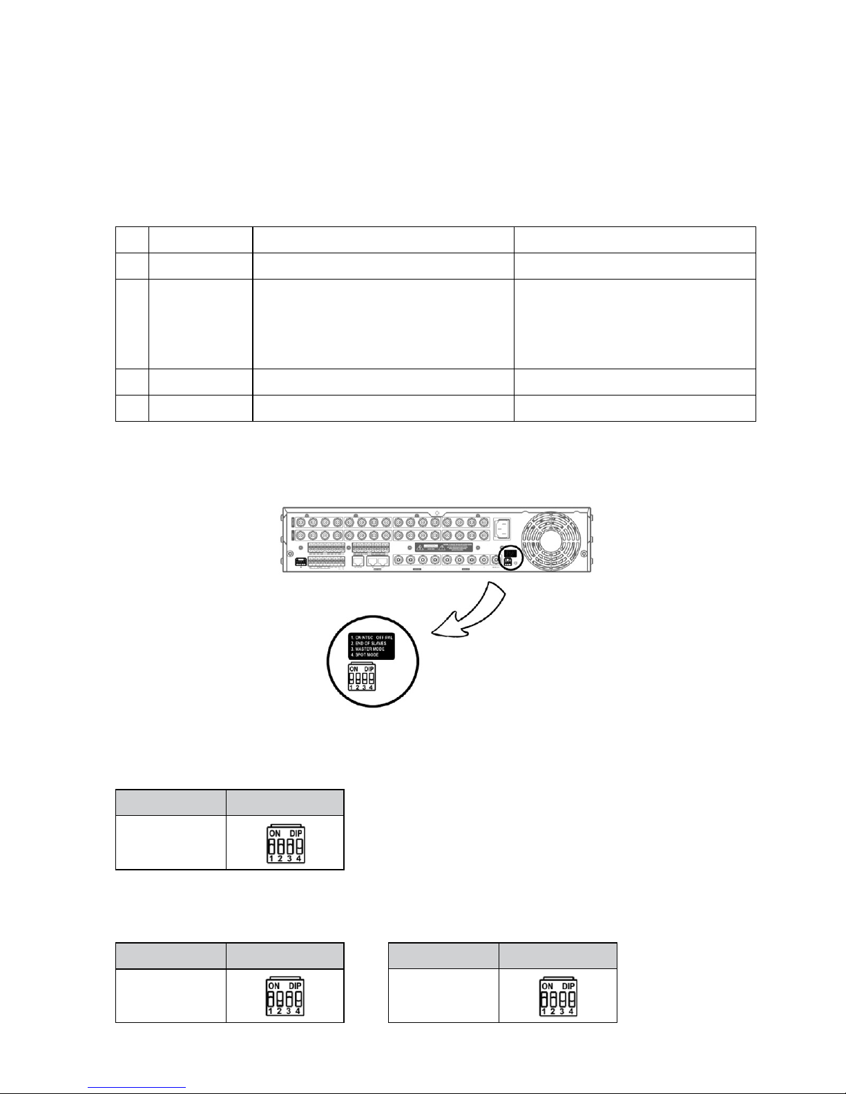
12 Option Switch Set the switch to the On (upward) or Off (downward) position depending on the video
signal format, termination or operation mode. Refer to Option Switch for details.
13 Factory Reset
Switch
Use only when to return all settings to the original factory settings.
See below for more details.
14 Power In Connect the power cord to the MMX and then to a wall outlet.
The MMX starts booting when power is applied.
NOTES:
• Do NOT connect a cable to the Loop BNC unless it is connected to another device because it will cause
poor quality video.
• To make connections on the Alarm Connector Strip, press and hold the button and insert the wire in the
hole below the button. After releasing the button, tug gently on the wire to make certain it is connected.
To disconnect a wire, press and hold the button above the wire and pull out the wire.
• Camera surveillance may be prohibited by laws that vary by region. Check the laws in your area before
using this product for surveillance purposes.
• Use a STP Cat5E cable which is 5m long or shorter when daisy-chaining MMXs. Using other types of cables
may cause video noise, and the connection of a cable longer than 5m might cause the connection failure.
CAUTIONS:
•
The network connector is not designed to be connected directly with cable or wire intended for outdoor use.
• This product is also designed for IT power system with phase-to-phase voltage 230V.
WARNING: ROUTE POWER CORDS SO THAT THEY ARE NOT A TRIPPING HAZARD. MAKE CERTAIN THE POWER
CORD WILL NOT BE PINCHED OR ABRADED BY FURNITURE. DO NOT INSTALL POWER CORDS UNDER
RUGS OR CARPET. THE POWER CORD HAS A GROUNDING PIN. IF YOUR POWER OUTLET DOES NOT
HAVE A GROUNDING PIN RECEPTACLE, DO NOT MODIFY THE PLUG. DO NOT OVERLOAD THE CIRCUIT
BY PLUGGING TOO MANY DEVICES INTO ONE CIRCUIT.

10
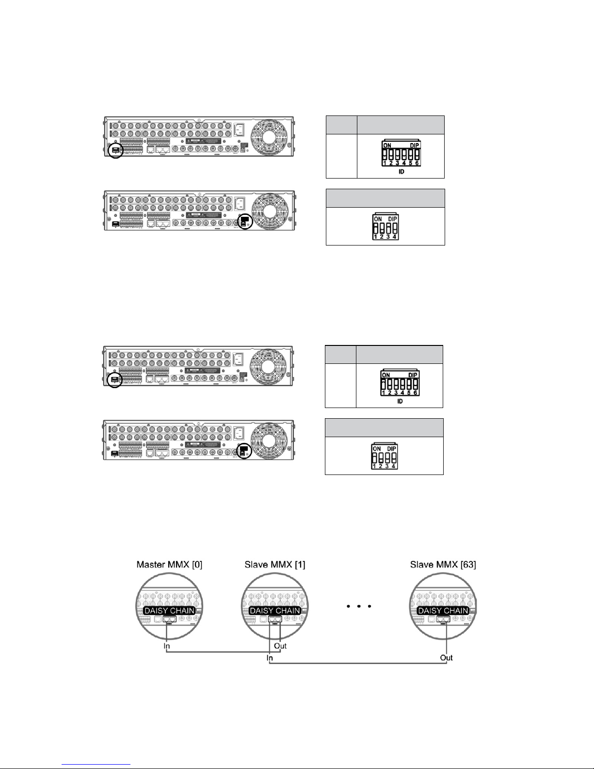
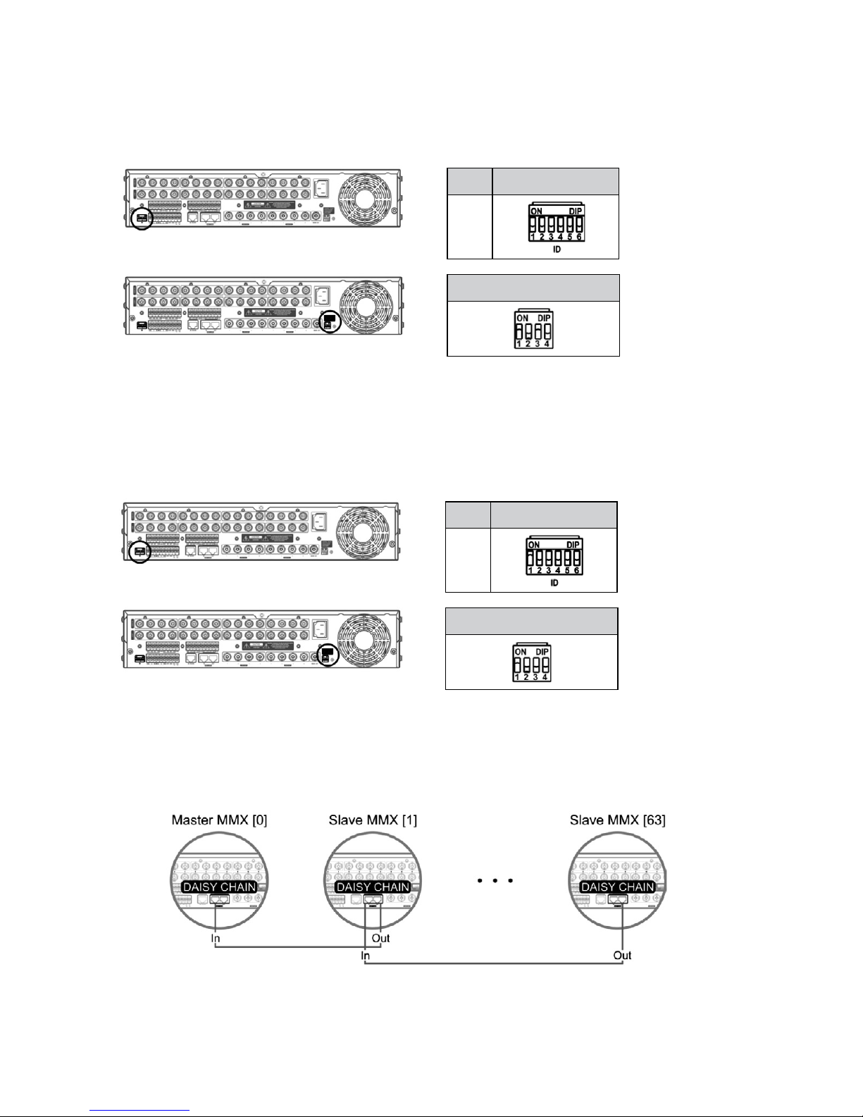
MMX ID Switch
Set up the MMX ID by using the MMX ID switch to distinguish the MMX from other MMXs for hardware distinction.
Every MMX should have its own unique ID, and the MMX system might not work properly if more than one MMX has
the same ID. The MMX ID switch is set up with the binary scale, and setting all switches to the On (upward) position
indicates „0” and to the Off (downward) position indicates „63”. Set up the switch to „0” for a master MMX, „1” to
„63” for slave MMXs and „0” to „3” for spot MMXs. Refer to
Appendix 2 – MMX ID Switch Settings for details on
setting the switches for each ID from „0” to „63”.
NOTE: When setting the switch for slave MMXs, the ID should be assigned in order starting from „1”.
Otherwise, the MMX system might not work properly.
ID MMX ID Switch
0
1
63
Daisy Chain In/Out
It is required to daisy-chain all slave MMXs to a master MMX by using the STP Cat5E cable with an RJ-45 jack when
using more than one MMX. Connect a cable from the
DAISY CHAIN OUT port of a MMX with a higher ID number to
the DAISY CHAIN IN port of a MMX with a lower ID number in order as follows:
NOTES:
•
Daisy chain in this manual refers to the connection between a master MMX and slave MMXs through the
DAISY CHAIN ports on the rear panel of the master MMX and slave MMXs. All slave MMXs are connected to
the master MMX through the daisy chain.
• The slave MMXs should be daisy-chained in order from the slave MMX with the highest ID number to the
slave MMX with ID „1”, and the slave MMX with ID „1” should be daisy-chained to a master MMX directly.
Otherwise, the MMX system might not work properly.
• The number of MMXs will be displayed at the bottom right corner on the monitor. (‘the number of properly
operating MMXs among the daisy-chained MMXs’ / ‘the number of networked MMXs among the daisy-
chained MMXs’ / ‘the total number of daisy-chained MMXs’)
11
• It is required to perform factory reset in all daisy-chained MMXs and set up the system all over again
to complete the connections. The MMX system might not work properly when applying previously saved
settings to the MMXs after the factory reset. Refer to Factory Reset for details on the factory reset.
Option Switch
Set the switch to the On or Off position depending on the usage as follows:
No. Description ON (Upward) OFF (Downward)
1 ON/OFF Video signal format is NTSC. Video signal format is PAL.
2 END OF SLAVES • The MMX is a slave MMX with the highest
ID number among all slave MMXs.
• The MMX is a spot MMX.
• The MMX is the only one MMX.
Other cases except when the switch is
set to the ON position.
3 MASTER MODE The MMX is a master MMX. The MMX is a slave MMX or spot MMX.
4 SPOT MODE The MMX is a spot MMX. The MMX is a master MMX or slave MMX.
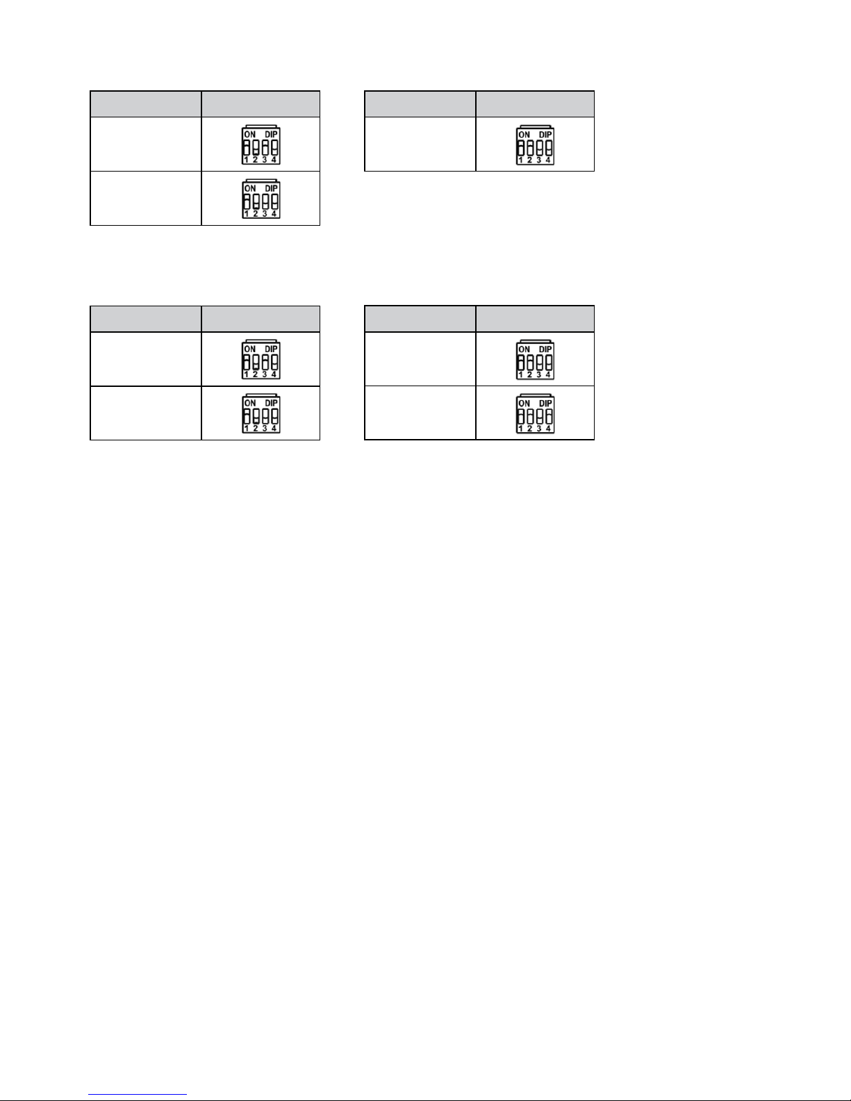
The following is examples of the option switch settings in a master MMX, slave MMXs and spot MMXs.
• When installing single MMX with the NTSC video signal.
MMD (ID) Option Switch
Master MMX [0]
MMD (ID) Option Switch
Master MMX [0]
• When installing a master MMX and one slave MMX with the NTSC video signal.
MMD (ID) Option Switch
Slave MMX [1]
12
MMD (ID) Option Switch
Master MMX [0]
Slave MMX [1] ~
Slave MMX [2]
• When installing a master MMX and three slave MMXs with the NTSC video signal.
MMD (ID) Option Switch
Slave MMX [3]
MMD (ID) Option Switch
Master MMX [0]
Slave MMX [1] ~
Slave MMX [14]
• When installing a master MMX, 16 slave MMXs and four spot MMXs with the NTSC video signal.
MMD (ID) Option Switch
Slave MMX [15]
Spot MMX [0] ~
Spot MMX [3]
NOTES:
• The option switch setting determines the operation mode of MMXs: Master MMX, slave MMX, spot MMX.
− A master MMX is a basic MMX in the MMX system and has information of slave MMXs daisy-chained to
the master MMX. A main monitor is connected to the master MMX and provides various functions.
− A slave MMX is subjective to a master MMX and daisy-chained to the master MMX for proper function.
It does not have its own settings except the IP address setting, and the settings of a master MMX are
applied to slave MMXs automatically.
− A spot MMX is connected to a master MMX and slave MMXs and displays video from spot outputs of a
master MMX and slave MMXs on up to four spot MMX monitors at the same time.
• It is required to perform factory reset in all daisy-chained MMXs and set up the system all over again to
complete the settings. The MMX system might not work properly when applying previously saved settings
to the MMXs after the factory reset. Refer to
Factory Reset (see next page) for details on the factory reset.
Software Upgrade
You can upgrade the software remotely while the MMX is turned on by running the INIT program. The MMX restarts
after completing the upgrade. Refer to the INIT User’s Manual for details.
NOTE: All of the master MMX, slave MMXs daisy-chained to the master and spot MMXs connected to the
master MMX and slave MMXs should be upgraded with the same upgrade file. Otherwise, the MMX
system might not work properly.
13
Factory Reset
This switch will only be used on the rare occasions that you want to return all the settings to the original factory
settings.
CAUTION: When performing a Factory Reset, you will lose any settings you have saved.
Turn the MMX off. –> Turn it on again. While the MMX is initializing, the front panel LEDs will blink. –> When the
front panel LEDs blink, poke a straightened paperclip into the factory reset switch hole. –> Hold the switch until a
buzzer sounds. –> The MMX resets to factory defaults and restarts after completing the factory reset.
You can perform a factory reset remotely while the MMX is turned on by running the INIT program and selecting the
Reset – Factory Reset menu. The MMX restarts after completing the factory reset. Refer to the INIT User’s Manual for
details on remote factory resetting.
NOTE: The system should be set up all over again after performing the factory reset. The MMX system might
not work properly when applying previously saved settings to the MMXs after the factory reset.
4. Case Installation
All devices including MMXs should be networked via Ethernet.
14
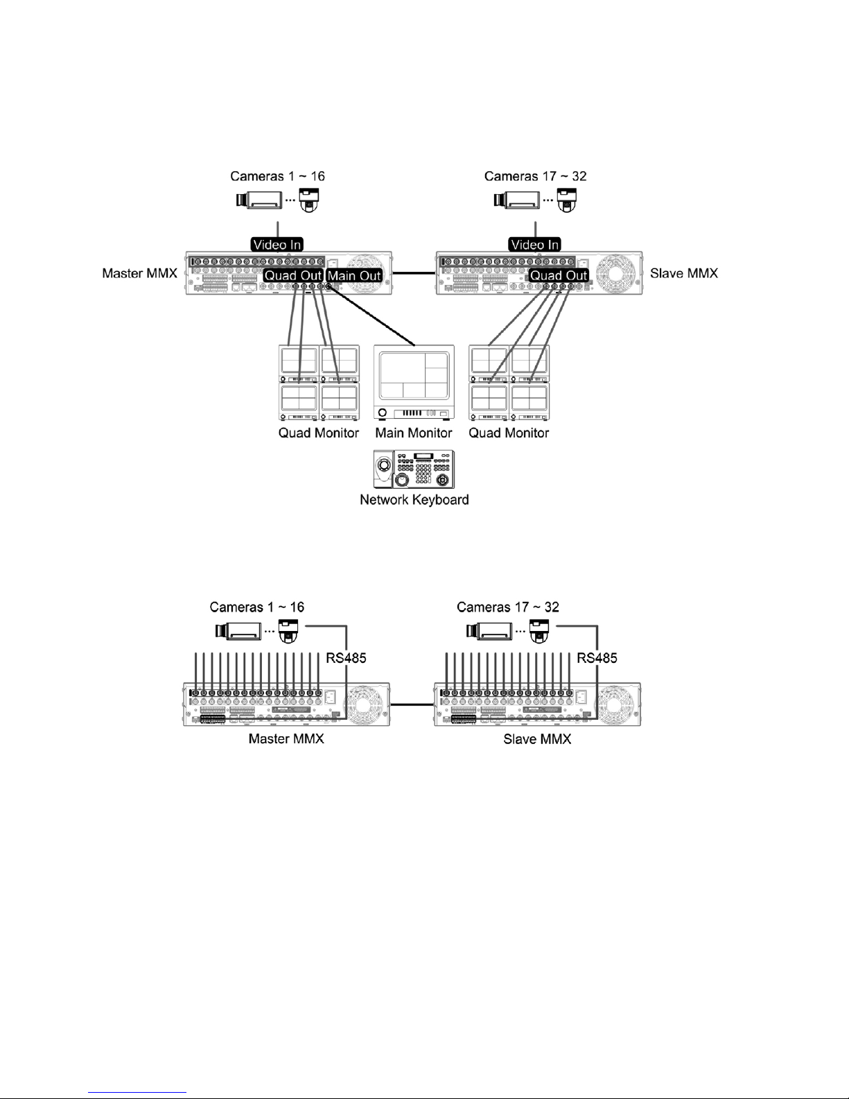
4.1 Medium-Sized System (without DVRs)
When connecting cameras directly to the MMXs, you can monitor video of user-defined channels on monitors connected to the MMXs.
1. Connect cameras to the Video In ports of a master MMX and slave MMXs.
15
2. Set up the MMX ID and options by using the MMX ID switch and option switch on the rear panel of the MMX.
Refer to
MMX ID Switch and Option Switch for details.
[Master MMX] Set up the MMX ID to „0” and the MASTER MODE switch to the On position.
ID MMX ID Switch
0
Option Switch
[Slave MMX] Set up the unique MMX ID for each slave MMX from „1” to „63” in order and set the END OF SLAVES
switch to the On or Off position depending on the slave MMXs’ ID setting. Set the END OF SLAVES switch of the slave
MMX with the highest ID number to the On position and the other to the Off position.
ID MMX ID Switch
1
Option Switch
3. Connect slave MMXs to a master MMX through the DAISY CHAIN port on the rear panel.
Refer to Daisy Chain In/Out for details.
16
4. Connect a main monitor to a master MMX through the Main Out port, and quad monitors or spot monitors to
the master MMX and slave MMXs through the Quad Out or Spot Out ports. You can monitor video from any
camera in the main monitor in various layouts, and video from connected MMX on the quad or spot monitors in
the quad- or single-screen layout. Sequence and event monitoring are supported in each monitor.
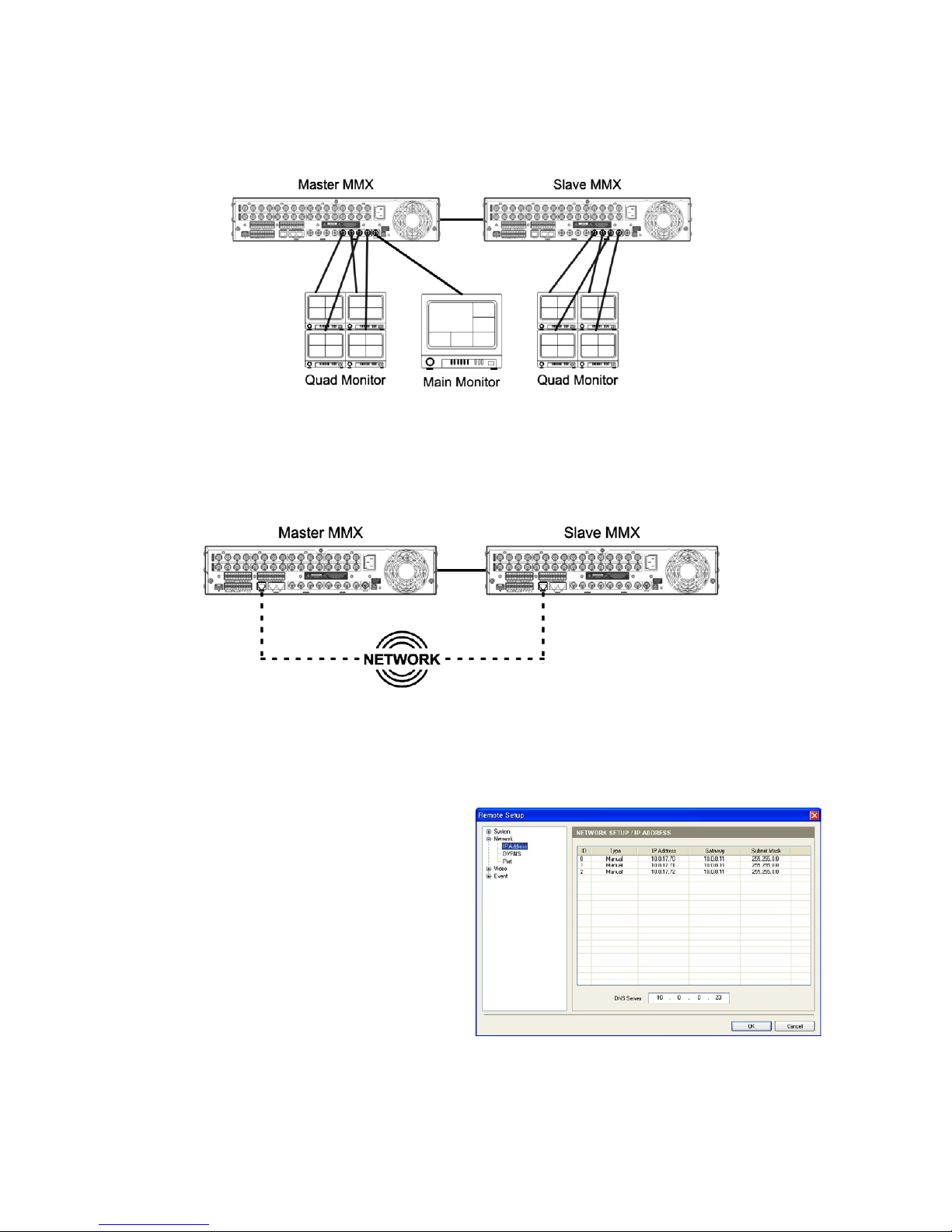
5. Connect MMXs to network via Ethernet connections through the
NETWORK port on the rear panel.
All MMXs should be networked via Ethernet.
6. Run the INIT program and connect to the master MMX. Refer to the INIT User’s Manual for details on the
INIT program.
6.1. Go to the following menus: Remote Setup
–> Network –> IP Address
Set up the network connection information
of a master MMX and slave MMXs.
The master MMX and slave MMXs’ IDs set
by using the MMX ID switch on the rear panel
are displayed in the list (Master MMX ID: 0,
slave MMX ID: 1 to 63).
17
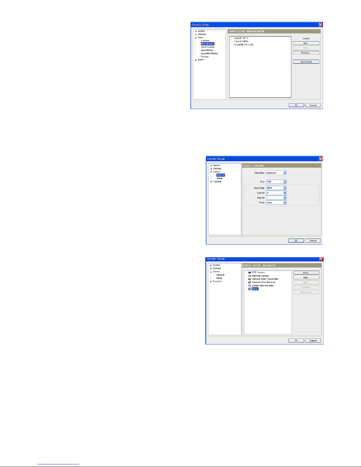
6.2. Go to the following menus: Remote Setup –>
Video –> Main Monitor, Quad Monitor, Spot
Monitor
Select a monitor and click the
Edit button to
set up layouts. Refer to Chapter 5 – Monitor
Layout and Control for details on setting up
the monitor layout.
7. Run the INIT program and connect to a network keyboard. Refer to the User’s Manual of the network keyboard
for details on setting up the network keyboard.
7.1. Go to the following menus: Remote Setup –>
Device –> General
Select
Advanced from the Device type drop-down
menu.
7.2. Go to the following menus: Remote Setup –>
Device –> Setup
Click
Matrix in the device list and the Scan or Add
button to register the MMX on the network keyboard.
18
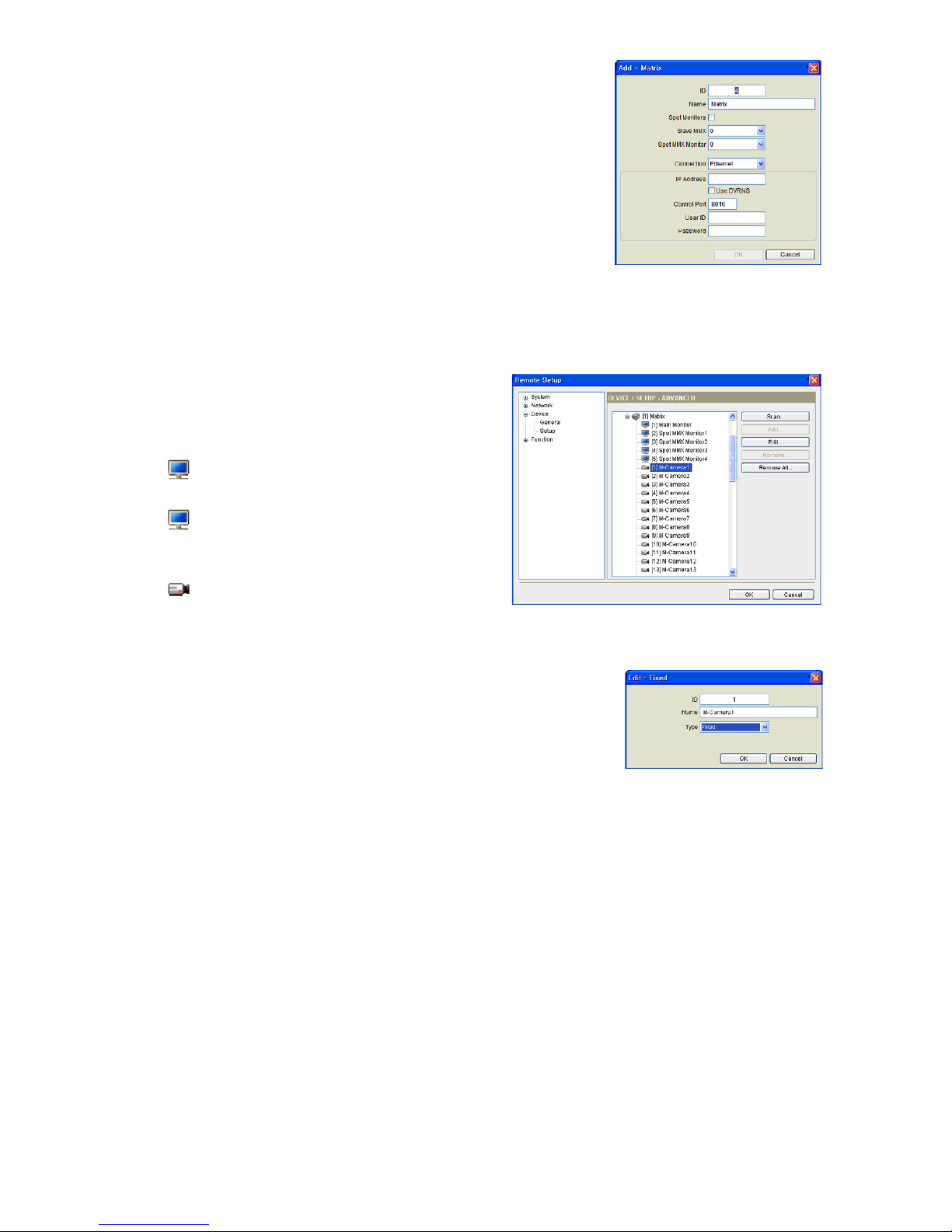
7.4. Click the MMX pull-down menu in the device list,
then the registered MMX’s pull-down menu.
A list of monitors and cameras supported in the
MMXs is displayed.
• [ID] Main Monitor: Displays the monitor ID
and type.
• [ID] Spot Monitor No.: Displays the monitor
ID, monitor type and the Spot Out number of the
MMX or slave MMXs.
•
[ID] „Camera Name”: Displays the ID and
name of the camera connected to the master MMX
and slave MMXs.
7.5. Click a camera in the list and the Edit button.
Set up the camera information.
• ID: The network keyboard assigns the ID automatically when the
MMX is registered, and you can change the ID. The ID will be used
to distinguish the camera from other cameras when controlling it
by using a network keyboard, so each camera should have its own
unique ID.
• Type: Set up the camera type.
– Fixed: Select if the camera is not a PTZ camera.
– PTZ Camera: Select if the camera is a PTZ camera.
You can control the PTZ camera by using a network keyboard.
7.3. Set up the registration information and click the
OK button.
• ID: The network keyboard assigns the ID automatically when the
MMX is registered, and you can change the ID. The ID will be used
to distinguish the MMX from other devices when controlling the
MMX by using a network keyboard, so each device should have
its own unique ID.
• Spot Monitor: Select to control spot monitors connected to the
master MMX and slave MMXs.
• Slave MMX: Select the number of slave MMXs daisy-chained
to the master MMX. The slave MMXs are registered on the net work keyboard automatically when the master MMX is registered.
• IP Address, Control Port, User ID, Password: Enter the IP address,
port number, user ID and password for the connection to the MMX.
19
4.2 Medium-Sized System (with DVRs)
When connecting DVRs to the MMXs, you can monitor video of user-defined channels on monitors connected to the
MMXs. You can also control the DVRs by using a network keyboard.
1. Connect the loop out of DVRs to monitor video to the Video In ports of a master MMX and slave MMXs.
2. Connect the
Main Out of DVRs to control to the Video In ports of a master MMX or a slave MMX. The number
of cameras that can be connected to the DVRs decreases as the number of DVRs connected to the master MMX
and slave MMXs. You can connect the Main Out of all DVRs to the Video In ports of one MMX or connect
individually the Main Out of each DVR to the Video In port of the MMX which the DVR is connected. You will use
the Video In number of MMXs when registering the MMX on a network keyboard for the remote control, so
please write down the Video In numbers of MMXs.
20
3. Set up the MMX ID and options by using the MMX ID switch and option switch on the rear panel of the MMX.
Refer to
MMX ID Switch and Option Switch for details.
[Master MMX] Set up the MMX ID to „0” and the MASTER MODE switch to the On position.
ID MMX ID Switch
0
Option Switch
[Slave MMX] Set up the unique MMX ID for each slave MMX from „1” to „63” in order and set the END OF
SLAVES switch to the On or Off position depending on the slave MMXs’ ID setting. Set the END OF SLAVES
switch of the slave MMX with the highest ID number to the On position and the other to the Off position.
ID MMX ID Switch
1
Option Switch
4. Connect slave MMXs to a master MMX through the DAISY CHAIN port on the rear panel.
Refer to Daisy Chain In/Out for details.
21
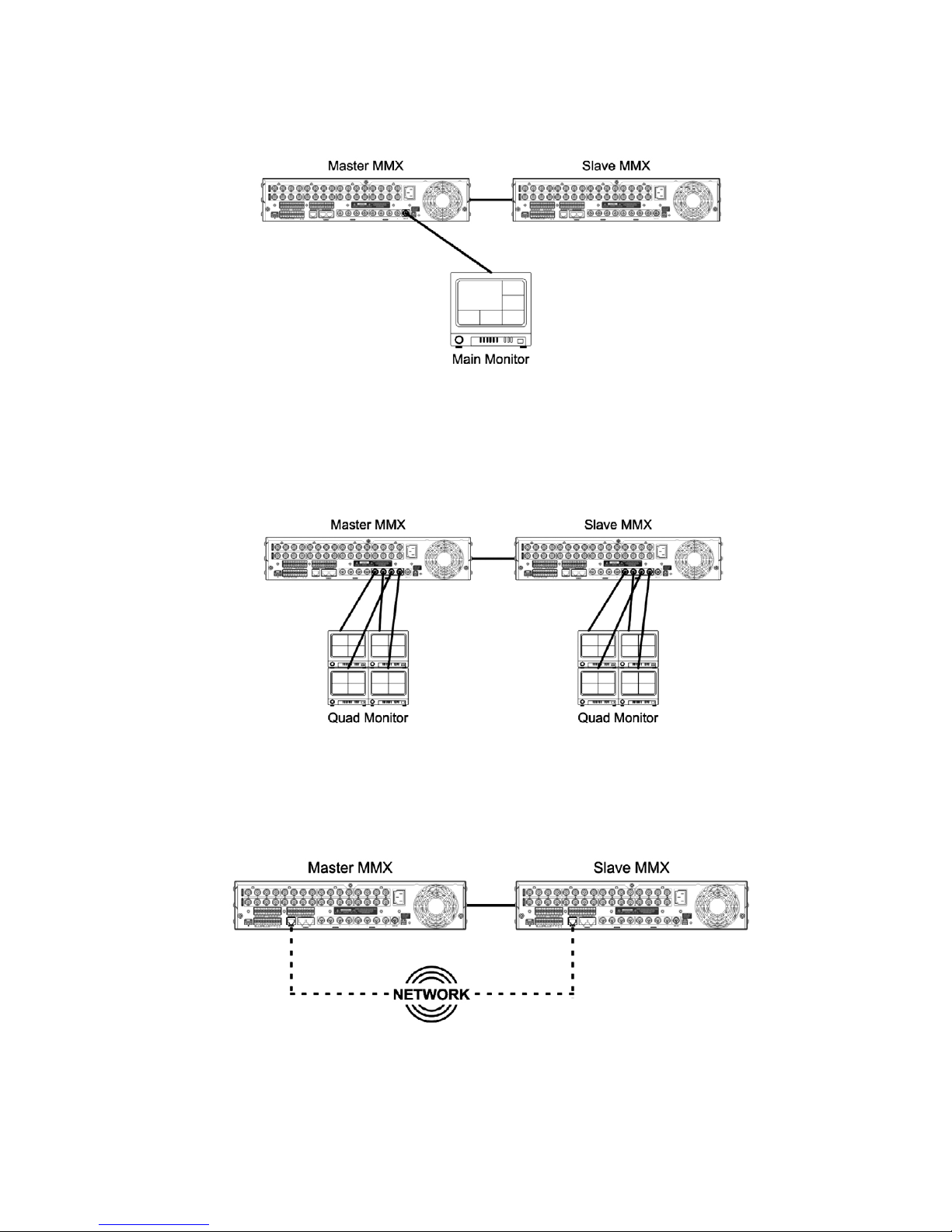
5. Connect a main monitor to a master MMX through the Main Out port. You can monitor video from any cameras
in various layouts, and sequence and event monitoring are supported. You can also control DVRs connected to
the master MMX or slave MMXs.
7. Connect MMXs to network via Ethernet connections through the
NETWORK port on the rear panel.
All MMXs should be networked via Ethernet.
6. Connect quad monitors or spot monitors to the master MMX and slave MMXs through the Quad Out or Spot Out
ports. You can monitor video from the connected MMX in quad- or single-screen layout, and sequence and event
monitoring are supported in each monitor.

22
8. Run the INIT program and connect to the master MMX. Refer to the INIT User’s Manual for details on the
INIT program.
8.1. Go to the following menus: Remote Setup
–> Network –> IP Address
Set up the network connection information
of a master MMX and slave MMXs.
The master MMX and slave MMXs’ IDs set
by using the MMX ID switch on the rear panel
are displayed in the list (Master MMX ID: 0,
slave MMX ID: 1 to 63).
8.2. Go to the following menus: Remote Setup –>
Video –> Main Monitor, Quad Monitor, Spot
Monitor
Select a monitor and click the
Edit button to
set up layouts. Refer to Chapter 5 – Monitor
Layout and Control for details on setting up
the monitor layout.
9. Run the INIT program and connect to a network keyboard. Refer to the User’s Manual of the network keyboard
for details on setting up the network keyboard.
9.1. Go to the following menus: Remote Setup –>
Device –> General
Select
Advanced from the Device type drop-down
menu.
23
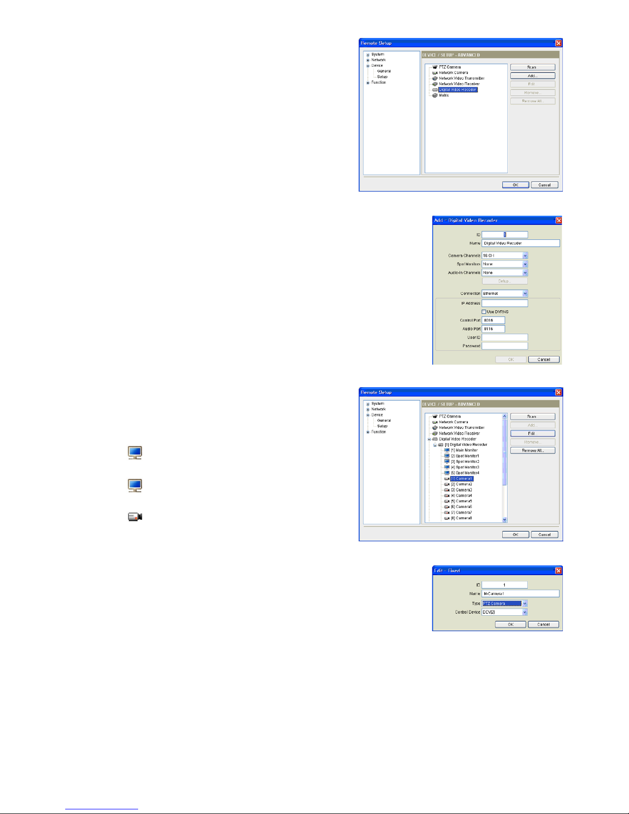
9.2. Go to the following menus: Remote Setup –>
Device –> Setup
Click
Digital Video Recorder in the device list and
the Add button to register the DVR connected to the
MMX. You can control the DVRs by using a network
keyboard.
9.3. Set up the registration information and click the
OK button.
• ID: The network keyboard assigns the ID automatically when the
DVR is registered, and you can change the ID. The ID will be used
to distinguish the DVR from other devices when controlling the
DVR by using a network keyboard, so each device should have
its own unique ID.
• Connection: Select Ethernet and enter the IP address, port
numbers (Control Port: Watch port), user ID and password for the
connection to the DVR.
9.4. Click the Digital Video Recorder pull-down menu
in the device list, then the registered DVR’s pull down menu. A list of monitors and cameras
supported in the DVR is displayed.
• [ID] Main Monitor: Displays the monitor ID
and type.
• [ID] Spot Monitor No.: Displays the monitor ID,
monitor type and the Spot Out number of the DVR.
•
[ID] „Camera Name”: Displays the ID and
name of the camera.
9.5. Click a camera in the list and the Edit button.
Set up the camera information.
• ID: The network keyboard assigns the ID automatically when the
DVR is registered, and you can change the ID. The ID will be used
to distinguish the camera from other cameras when controlling it
by using a network keyboard, so each camera should have its own
unique ID.
• Type: Set up the camera type.
− Fixed: Select if the camera is not a PTZ camera.
− PTZ Camera: Select if the camera is a PTZ camera and select
the device that controls the PTZ camera.
24
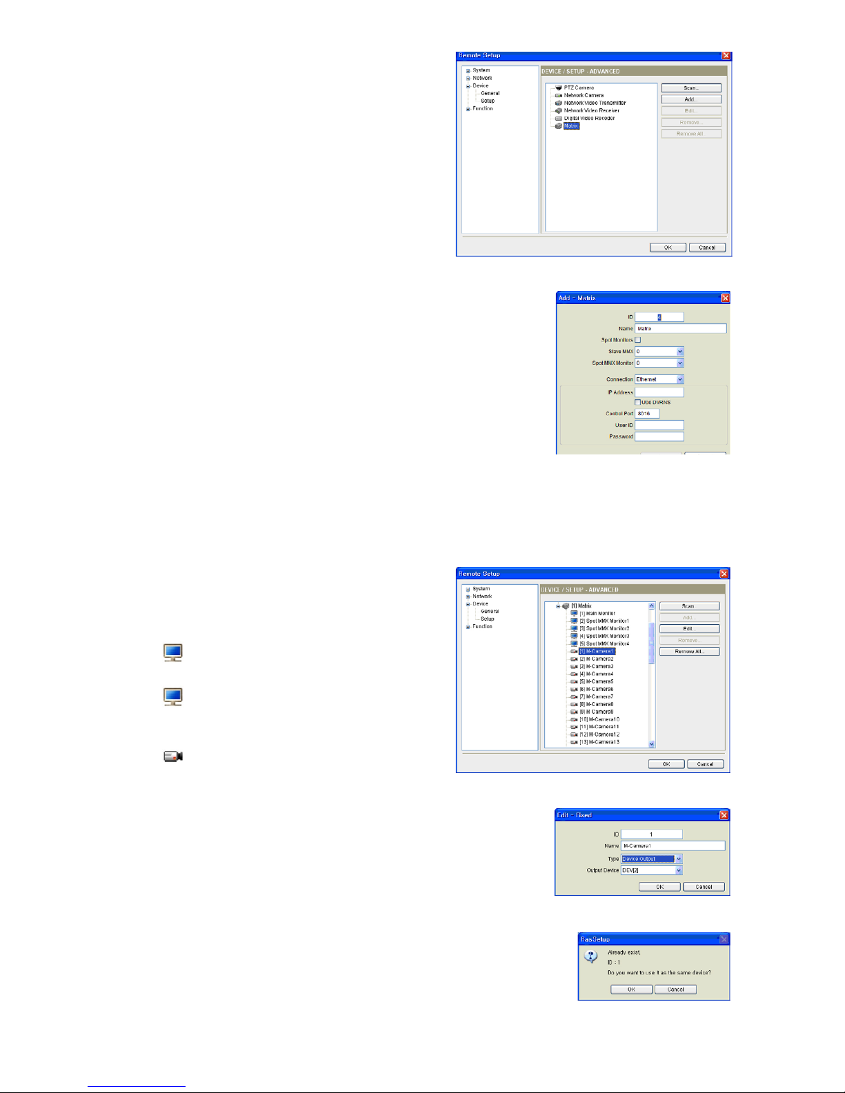
9.6. Go to the following menus: Remote Setup –>
Device –> Setup
Click
Matrix in the device list and the Scan or Add
button to register the master MMX.
9.7. Set up the registration information and click the OK button.
•
ID: The network keyboard assigns the ID automatically when the
MMX is registered, and you can change the ID. The ID will be used
to distinguish the MMX from other devices when controlling the
MMX by using a network keyboard, so each device should have its
own unique ID.
• Spot Monitor: Select to control spot monitors connected to the
master MMX and slave MMXs.
•
Slave MMX: Select the number of slave MMXs daisy-chained to the
master MMX. The slave MMXs are registered on the network
keyboard automatically when the master MMX is registered.
•
IP Address, Control Port, User ID, Password: Enter the IP address,
port number, user ID and password for the connection to the MMX.
9.8. Click the
Matrix pull-down menu in the device
list, then the registered MMX’s pull-down menu.
A list of monitors and cameras supported in the
MMXs is displayed.
• [ID] Main Monitor: Displays the monitor ID
and type.
• [ID] Spot Monitor No.: Displays the monitor
ID, monitor type and the Spot Out number of the
MMX or slave MMXs.
• [ID] „Camera Name”: Displays the ID and
name of the camera.
9.9. Click a camera in the list and the Edit button. Set up the camera
information.
•
ID: Set up the camera ID. The MMX’s camera ID should be the same
as the camera ID of the DVR connected to the MMX. Otherwise, two
different IDs will be assigned to one camera. When clicking the OK
button displays a message box to confirm using the existing ID. Click
the OK button to complete the changes. The ID will be used to distinguish the camera from other cameras when controlling it by using a
network keyboard, so each camera should have its own unique ID.
• Type: Set up the camera type.
− Device Output: Select if the Main Out of the DVR is connected
to the Video In port of the MMX, and select the DVR.
You can control the DVR by using a network keyboard.
 Loading...