

Eneo Minitrax HDD-1012PTZ1080, HDD-2030PTZ1080 Full Manual

Full Manual
Minitrax
1/2.8" Day/Night Dome Camera, PTZ
HDD-1012PTZ1080
II
CAUTION
RISK OF ELECTRIC SHOCK
DO NOT OPE N
CAUTION: TO RED UCE THE RISK OF ELECTRIC SHOCK,
DO NOT REM OV E COVER (O R BACK)
NO USER-SERVICEABLE PARTS INSIDE.
REFER SERVICING TO QUALIFIED SERVICE PERSONNEL.
WARNING
TO REDUCE THE RISK OF FIRE OR ELECTRIC SHOCK, DO
NOT EXPOSE THIS PRODUCT TO RAIN OR MOISTURE. DO
NOT INSERT ANY METALLIC OBJECTS THROUGH THE
VENTILATION GRILLS OR OTHER OPENINGS ON THE
EQUIPMENT.
CAUTION
EXPLANATION OF GRAPHICAL SYMBOLS
The lightning flash with arrowhead symbol, within an
equilateral triangle, is intended to alert the user to
the presence of uninsulated “dangerous voltage”
within the product’s enclosure that may be of
sufficient magnitude to constitute a risk of electric
shock to persons.
The exclamation point within an equilateral triangle
is intended to alert the user to the presence of
important operating and maintenance (servicing)
instructions in the literature accompanying the
appliance.

III
CE COMPLIANCE STATEMENT
WARNING
This is a Class A product. In a domestic environment this product may
cause radio interference in which case the user may be required to take
adequate measures.

IV
IMPORTANT SAFETY INSTRUCTIONS
1. Read these instructions.
2. Keep these instructions.
3. Heed all warnings.
4. Follow all instructions.
5. Do not use this apparatus near water.
6. Clean only with dry cloth.
7. Do not block any ventilation openings. Install in accordance with the
manufacturer’s instructions.
8. Do not install near any heat sources such as radiators, heat registers,
stoves, or other apparatus (including amplifiers) that produce heat.
9. Do not defeat the safet y purpose of the p olarized or grou nding-type plu g. A
polarized plug has two blades with one wider than the other. A groundin g
type plug has two blades a nd a third grounding prong. The wide blade or
the third prong is provided for your safety. If the provided plug does not fit
into your outlet, consult an electrician for replacement of the obsolete outlet.
10. Protect the power cord from being walked on or pinched particularly at
plugs, convenience receptacles, and the point where they exit from the
apparatus.
11. Only use attachments/accessories specified by the manufacturer.
12. Use only with the cart, stand, tripod, bracket, or table
specified by the manufacturer, or sold with the apparatus.
When a cart is used, use caution when moving the
cart/apparatus combination to avoid injury from tip-over.
13. Unplug this apparatus during lightning storms or when
unused for long periods of time.
14. Refer all servicing to qualified service personnel. Servicing is required
when the apparatus has been d amaged in any way, such as power-supply
cord or plug is damaged, liquid has been spilled or objects have fallen into
the apparatus, the apparatus has been exposed to rain or moisture, does
not operate normally, or has been dropped.
15. CAUTION – THESE SERVICING INSTRUCTIONS ARE FOR USE BY
QUALIFIED SERVICE PERSONNEL ONLY. TO REDUCE THE RISK OF
ELECTRIC SHOCK DO NOT PERFORM ANY SERVICING OTHER THAN
THAT CONTAINED IN THE OPERATING INSTRUCTIONS UNLESS YOU
ARE QUALIFIED TO DO SO.
16. Use satisfy clause 2.5 of IEC60950-1/UL60950-1 or Certified/Listed
Class 2 power source only.

V
Table of Contents
Chapter 1 — Introduction ............................................................................................... 1
1.1 Features ............................................................................................................................ 1
Chapter 2 — Installation and Configuration ................................................................. 2
2.1 Package Contents ............................................................................................................ 2
2.2 Installation ........................................................................................................................ 3
2.3 Basic Configuration of Dome Camera System ............................................................... 6
2.4 Setting Dome Camera Address (ID) ................................................................................ 7
2.5 Connections ...................................................................................................................... 7
2.6 Getting Started .................................................................................................................. 8
Chapter 3 — Program and Operation ............................................................................ 9
3.1 Dome Camera Selection ................................................................................................... 9
3.2 Accessing the On-Screen Menu Utility ........................................................................... 9
3.3 How to control the On-Screen Menu Utility .................................................................... 9
3.4 Auto Scan (Shortcut: SCAN) ......................................................................................... 10
3.5 Preset (Shortcut: PRST) ................................................................................................ 12
3.6 Shortcut of Preset Program ........................................................................................... 13
3.7 Tour (Shortcut: TOUR) ................................................................................................... 14
3.8 Pattern (Shortcut: PTRN) ............................................................................................... 16
3.9 Privacy Zone ................................................................................................................... 17
3.10 Camera Menu ................................................................................................................ 18
3.11 Dome Communication .................................................................................................. 21
3.12 Alarm ............................................................................................................................. 22
3.13 Dome Setup .................................................................................................................. 23
Appendix A — Specifications ...................................................................................... 30
Appendix B — Troubleshooting .................................................................................. 32
Appendix C — Fastrax Protocol .................................................................................. 33

1
Chapter 1 — Introduction
1.1 Features
The dome camera and the keyboard controller make up the building blocks for any
surveillance/security system. Using multiple keyboard controllers and multiple dome cameras, no
place is too large for monitoring. Extensible and flexible architecture facilitates remote control
functions for a variety of external switching devices such as multiplexers and DVRs.
• Built-in optical power zoom camera with True Night Shot function
• 240 Preset positions with the individual camera AE setup
• 8 Tours consist of Presets, Patterns, Auto Scans and other Tours can be programmed with
over 300 functions and preset locations. While moving, each Preset scan can be watched in
smooth Vector Scan mode.
• 16 Auto Scans with the normal, the vector, and the random mode and the endless Auto-Pan
with 13 speed steps
• 8 Patterns (up to 500 second) and 8 Privacy Zones
• 4 Alarm inputs, 2 Alarm outputs (5VTTL)
• Variable speed from 0.1°/sec to 380°/sec
Three Variable speed (SLOW, NORMAL, TURBO)
Turbo speed is 380°/sec with Ctrl key pressed.
• Pan/Tilt speed is inversely proportional to the zoom ratio with the option.
• Maximum speed is 380°/sec when Preset command.
• Auto Calibration from 0.1° to 6° (Tilt range is 0° to 180°)
• Programmable user preferences (alarm, preset, title, etc.)
• 180° Digital Flip
• Up to 3999 selectable camera addresses
• Function Run menu using DVR without function key (Pattern, Scan …)
• Built-in RS-485 receiver driver
• 12VDC or 24VAC for Dome
• Use satisfy clause 2.5 of IEC60950-1/UL60950-1 or Certified/Listed Class 2 power source only.
2
Chapter 2 — Installation and Configuration
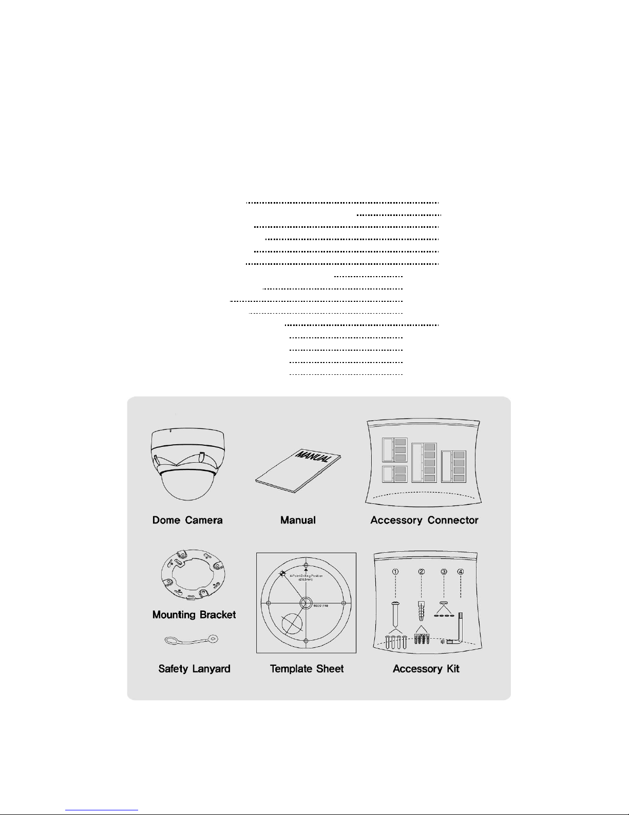
2.1 Package Contents
The dome camera is design ed with compact, small size, hard dome camera housing.
The housing is constructed of aluminum, steel and plastic. The housing is designed to be
mounted on a wall or a ceiling. The housing meets the Protection Classification IP66 standards
for dust and moisture resistance.
* Dome Camera 1
* Instruction Manual (This Document) 1
* Template Sheet 1
* Mounting Bracket 1
* Safety Lanyard 1
* Accessory Kit 1
1) Mounting screws (PH6 x 35.0) (4)
2) Plastic anchors (4)
3) O-Rings (4)
4) Torx wrench (1)
* Ac cessory Connector 1
1) 2-Pin Terminal Block (1)
2) 3-Pin Terminal Block (1)
3) 4-Pin Terminal Block (1)
4) 5-Pin Terminal Block (1)
3
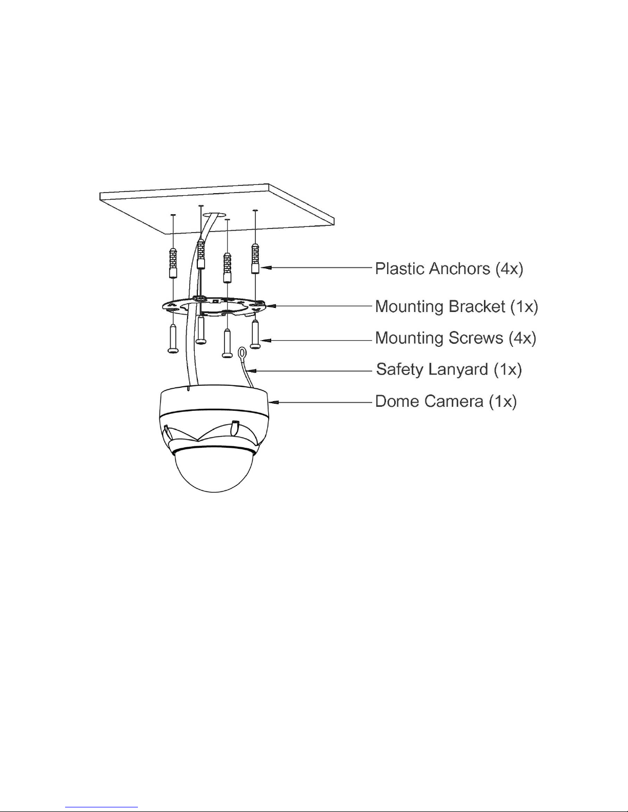
2.2 Installation
The dome camera is for use in surface or pendent mounting applications, and the mounting
member must be capable of supporting loads of up to 4.4 lb (2.0 kg). (Pendent mounting must
use pendent mount accessory.)
The dome camera’s mounting bracket should be attached to a structural object, such as hard
wood, wall stud or ceiling rafter that supports the weight of the dome camera.
CAUTION: A silicone rubber sealant must be applied to seal the housing to secure
waterproofing.
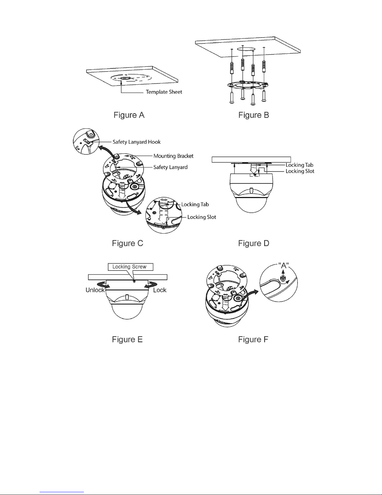
2.2.1 Locking Dome Camera
A. Make screw holes on the ceiling using the supplied mounting Template Sheet (Figure A).
B. Fix the Mounting Bracket to the ceiling using supplied Anchors (4x) and Mounting Screws (4x)
(Figure B).
C. Hook up the Safety Lanyard to the Safety Lanyard Hook of the Mounting Bracket (Figure C).
D. Align the locking tab on the bracket and the locking slot on the base of the dome (Figure D).
E. Turn the dome to the counterclockwise about 10 degree to the locked position (Figure E).
4
CAUTION: Before installing mounting bracket to surface pre-adjust the four mounting
screw s "A" on the base of the dome camera to best match the mounting
bracket locked position. Unscrew the locking screw on the side of the dome's
base and fit the tab of the mounting bracket into the locking slot. Screws "A"
should not be too tight or too loose when the dome is in the locked position.
After setting the proper positions of screws "A" remove the mounting bracket
and install it to the proper surface. If it is too difficult to lock the dome in
position after the mounting bracket has been installed readjust the screws "A"
by unscrewing them a small amount and try to install dome camera again.
5
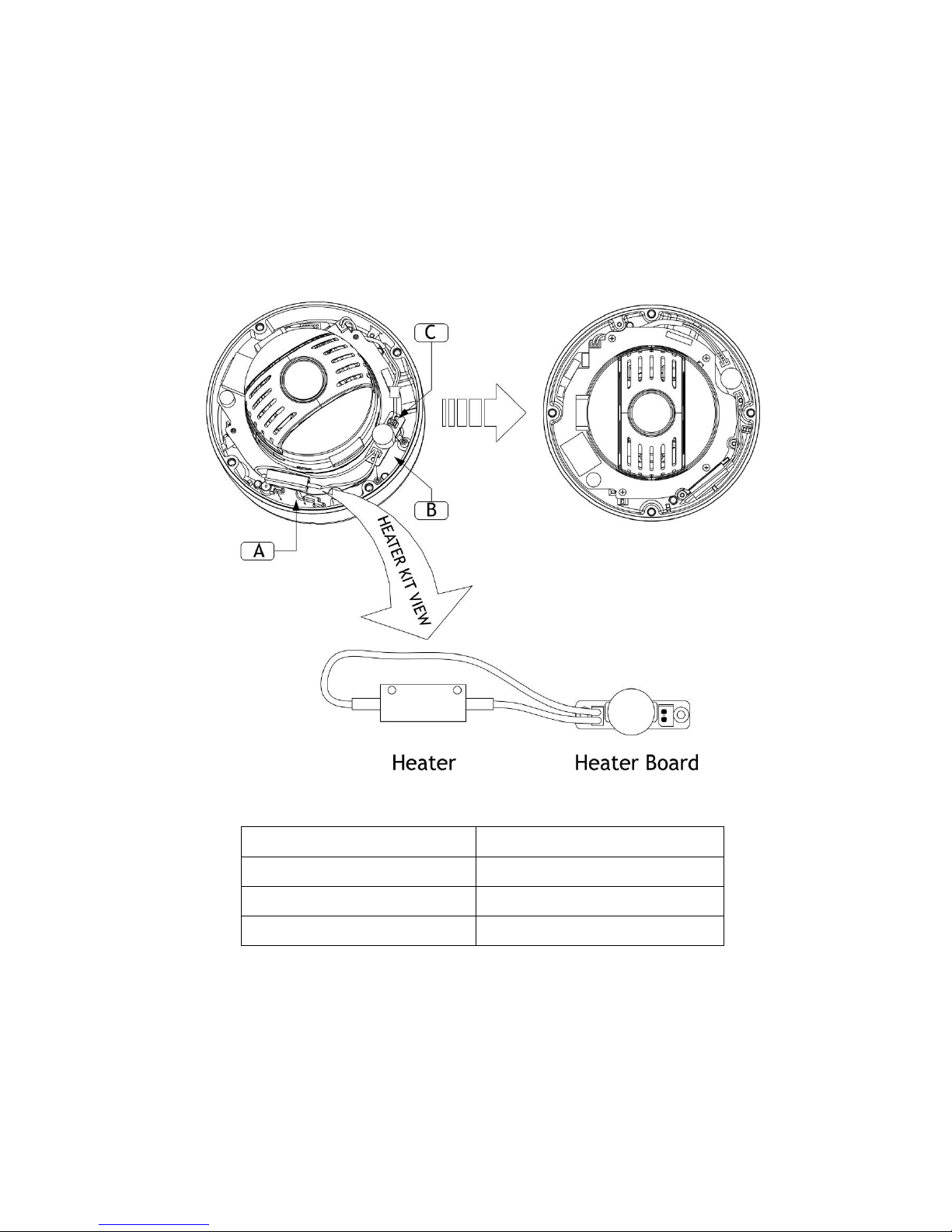
2.2.2 Heater Kit Installation
1. Assemble the Heater board to two bossed with screws.
Take a reference "B" in the bottom case as below.
2. Place the Heater in the slot "A".
Heater cable should be placed away from the Main board.
3. Plug the power connector to the socket "C" (J1) of the Heater board.
4. 24VAC is recommended to use for the camera power for stable operation with heater kit.
• HEATER (IF APPLICABLE)
Power Supply 24VAC
Power Consumption
10W
Heater ON
at 15°C
Heater OFF at 25°C
• POWER
Use satisfy clause 2.5 of IEC60950-1/UL60950-1 or Certified/Listed Class 2
power source only.
CAUTION: Please reset the camera after 30 minutes when installing it in situations colder
than -10°C.
6
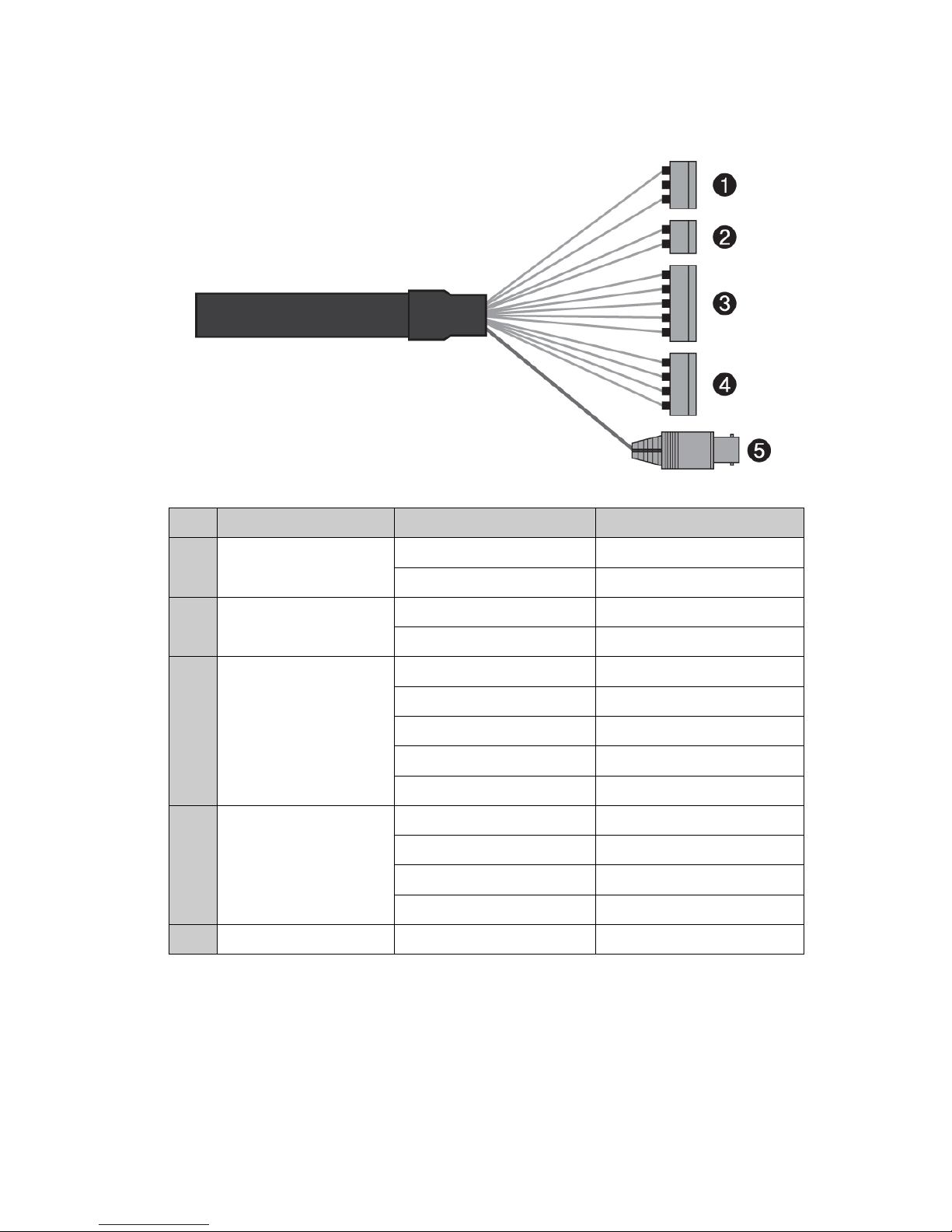
2.3 Basic Configuration of Dome Came ra System
No. Connector Wire Color Description
1
3-pin terminal block
RED 24VAC or 12VDC+
WHITE 24VAC or 12VDC-
2
2-pin terminal block
GREEN RS-485+
BLUE RS-485-
3
5-pin terminal block
GRAY ALARM INPUT 1
VIOLET ALARM INPUT 2
ORANGE ALARM INPUT 3
SKY BLUE ALARM INPUT 4
BLACK GND
4
4-pin terminal block
YELLOW ALARM OUTPUT 1
BLACK & WHITE GND
SKY BLUE & BALCK ALARM OUTPUT 2
ORANGE & BLACK GND
5
BNC jack BLUE HD-SDI Output
The dome camera must be installed by qualified service personnel in accordance with all local
and federal electrical and building codes.

7
2.4 Setting Dome Camera Address (ID)
To prevent damage, each dome camera must have a unique address (ID).
The factory default setting is 1.
Refer to ‘3.11 Dome Communication’ section for detailed information.
2.5 Connections
• Connecting to the RS-485
The dome camera can be controlled remotely by an external device or control system, such as
a control keyboard, using RS-485 half-duplex serial communications signals.
• Connecting HD-SDI Output connector
Connect the HD-SDI output (BNC) connector to the monitor or video input.
• Connecting Alarms
- A1,A2,A3,A4 (Alarm Input 1,2,3,4)
You can use external devices to signal the dome camera to react on events. Mechanical or
electrical switches can be wired to the A1,A2,A3,A4 (Alarm Input 1,2,3,4) and G (Ground)
connectors.
See Chapter 3 — Program and Operati on for configuring alarm input.
- G (Ground)
NOTE: All the connectors marked G or GND are common.
Connect the ground side of the alarm input and/or alarm output to the G (Ground) connector.
- AO1,AO2 (5VTTL Alarm Output 1,2)
The dome camera can activate external devices such as buzzers or lights. Connect the
device to the AO1,AO2 (Al arm Output 1,2) and G (Ground) connectors.
See Chapter 3 — Program and Operati on for configuring alarm output.
• Connecting the Power
Connect power of 12VDC or 24VAC 1.5A for the dome camera.
When using a 12VDC adapter, connect the positive (+) pole to the ‘+’ position and
the negative (-) pole to the ‘-’ position.
Use satisfy clause 2.5 of IEC60950-1/UL60950-1 or Certified/Listed Class 2 power source only.
 Loading...