

Eneo MEB-62V2812M0A, MEB-52F0036M0A, MEB-62V2812MBA, MED-52F0036MBA User Manual

EN
User Manual
1/2.9" HD Camera, Multisignal,
Day&Night, 1920x1080,
Infrared,
12VDC, IP66
MEB-62V2812M0A
MEB-52F0036M0A
MED-52F0036MBA
MEB-62V2812MBA
Operation Guide
Contents
ii
About This Document
Symbol Conventions
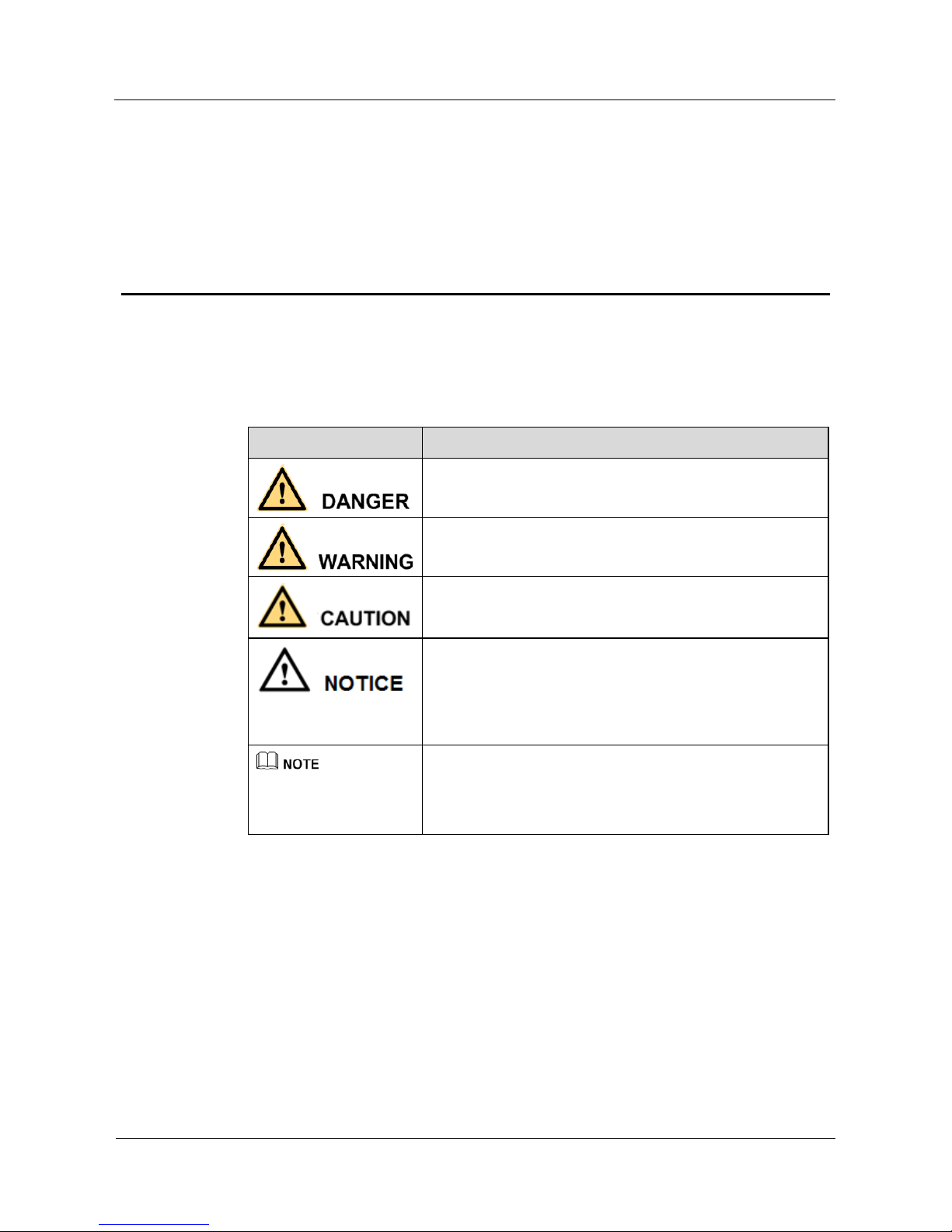
The symbols that may be found in this document are defined as follows.
Symbol Description
Indicates an imminently hazardous situation which, if not
avoided, will result in death or serious injury.
Indicates a potentially hazardous situation which, if not
avoided, could result in death or serious injury.
Indicates a potentially hazardous situation which, if not
avoided, may result in minor or moderate injury.
Indicates a potentially hazardous situation which, if not
avoided, could result in equipment damage, data loss,
performance deterioration, or unanticipated results.
NOTICE is used to address practices not related to personal
injury.
Calls attention to important information, best practices and
tips.
NOTE is used to address information not related to personal
injury, equipment damage, and environment deterioration.

Operation Guide
Contents
iii
Contents
About This Document .................................................................................................................... ii
1 MEB-62V2812M0A / MEB-52F0036M0A ................................................................................. iv
2 MED-52F0036MBA / MED-62V2812MBA .............................................................................. vi
3 OSD Main Menu ........................................................................................................................... 1
4 OSD Setting ................................................................................................................................... 3
Operation Guide
Contents
iv
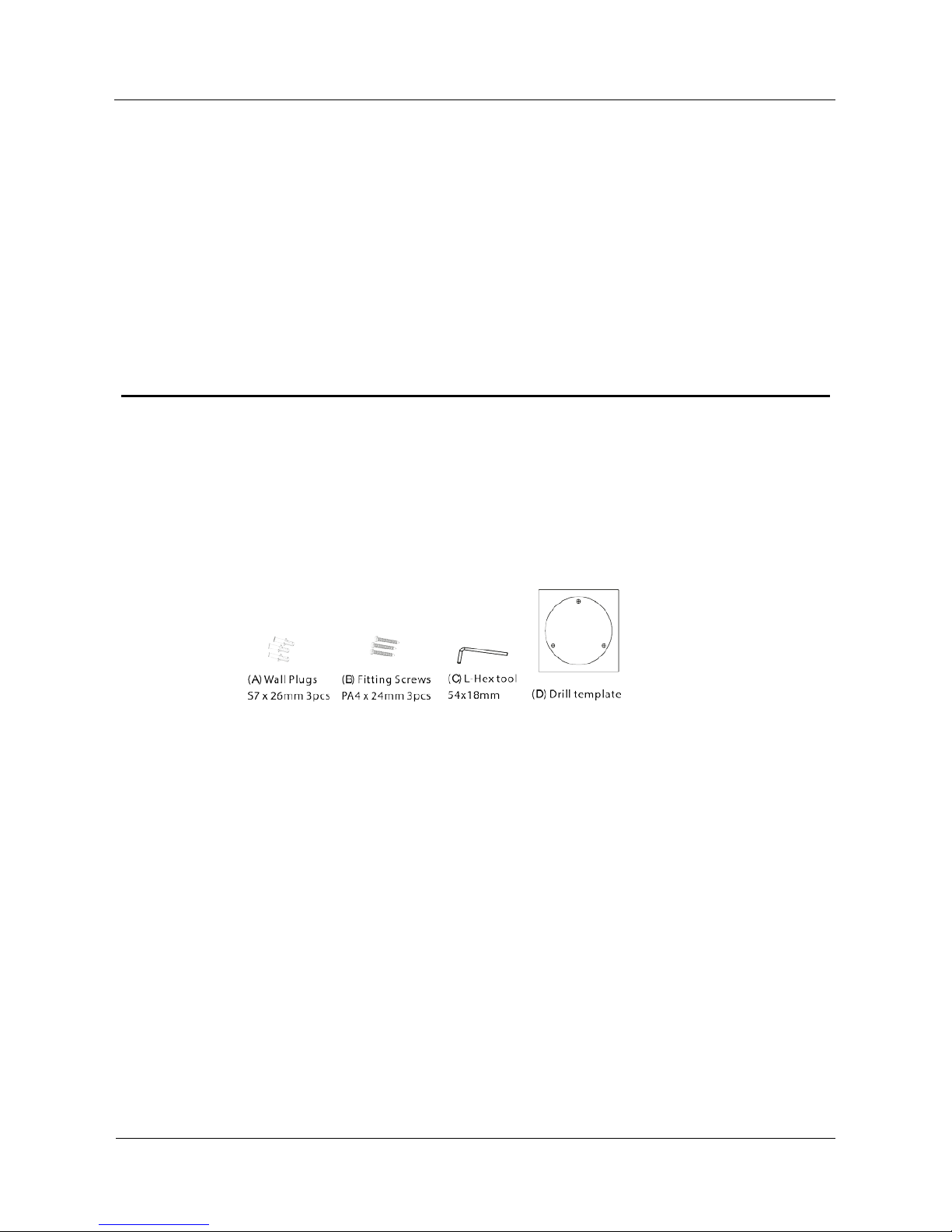
1 MEB-62V2812M0A / MEB-52F0036M0A
1.1 Parts supplied
Operation Guide
Contents
v
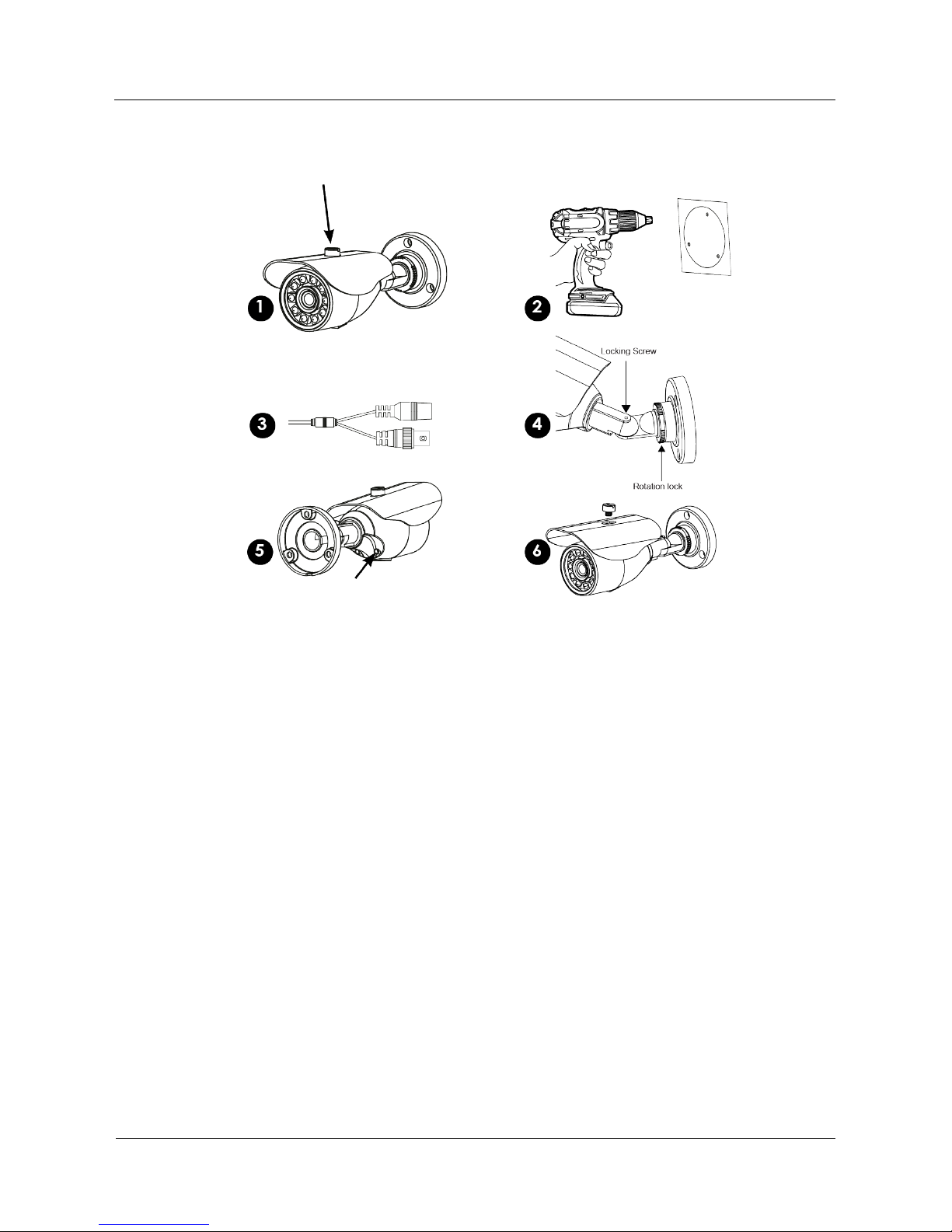
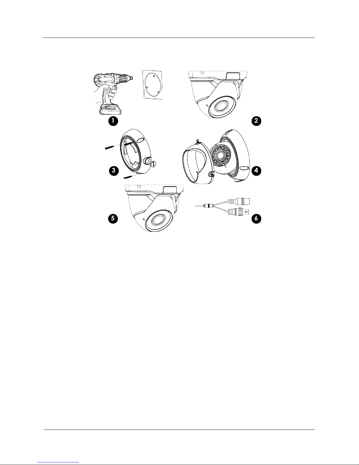
1.2 Installation
1. Remove sun shield from camera to aid simpler installation (optional requirement).
2. Use drill template (D) as to guide to drill and attach camera to surface as required.
Holes on bracket are 120 degree apart, so three holes are required.
3. With camera attached you can now connect power, check device working.
4. Using the (C) L-Hex tool you position left-right up/down and lock into place. The
rear position rotation allows turning of angle turn anti-clockwise to loosen.
5. Adjust zoom & focus using small flat blade. (Vari-focal model only)
6. Replace the sun visor if removed from step 1. Check IR LEDs are working by cover
ing the photocell of camera, the IR LEDs will give a faint red glow.
Don’t look at IR LEDs for long periods of time, as you could damage your eyes!
Operation Guide
Contents
vi
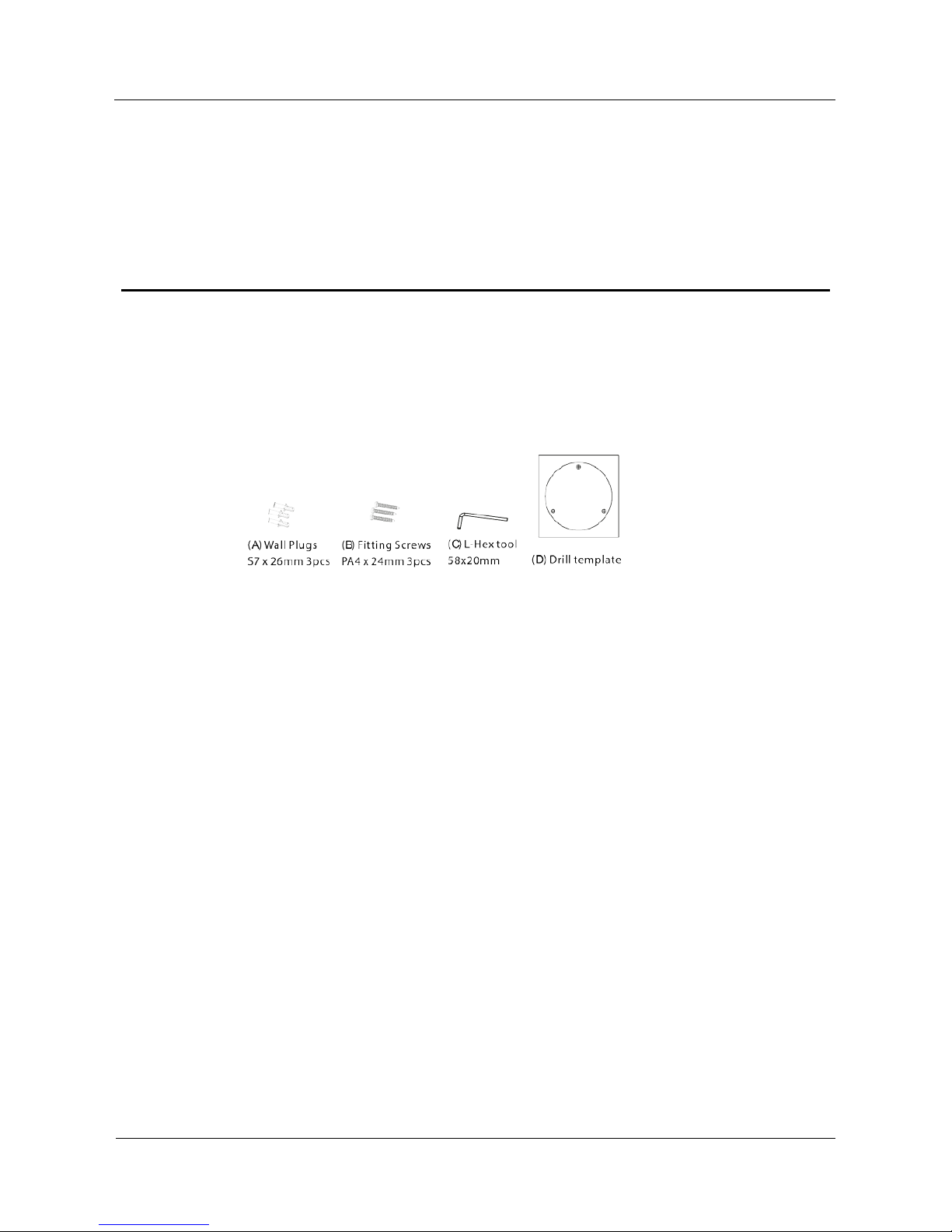
2 MED-52F0036MBA / MED-62V2812MBA
2.1 Parts supplied
Operation Guide
Contents
vii
2.2 Installation
1. Use supplied template to drill holes for (A) plugs
2. Remove locking cover using supplied (C) L-key. Optional requirement
3. ttach base part to surface with (B) screws. Use conduit if required.
4. Re-attach Cover and position camera then lock cover screws with L-Key.
5. Adjust the zoom & focus using flat blade tool. (Vari-Focal models only)
6. Wipe clean the front glass to stop potential IR Led smear at night.
7. Connect power, feeding through conduit may require this stage to be completed before
adjustment is made. Check IR LEDs are working by covering the photocell of camera,
the IR LEDs will give a faint red glow.
Don’t look at IR LEDs for long periods of time, as you could damage your eyes!
Operation Guide
3 OSD Main Menu
1
3 OSD Main Menu
3.1 Procedure
3.1.1 Camera Control Using Five Buttons
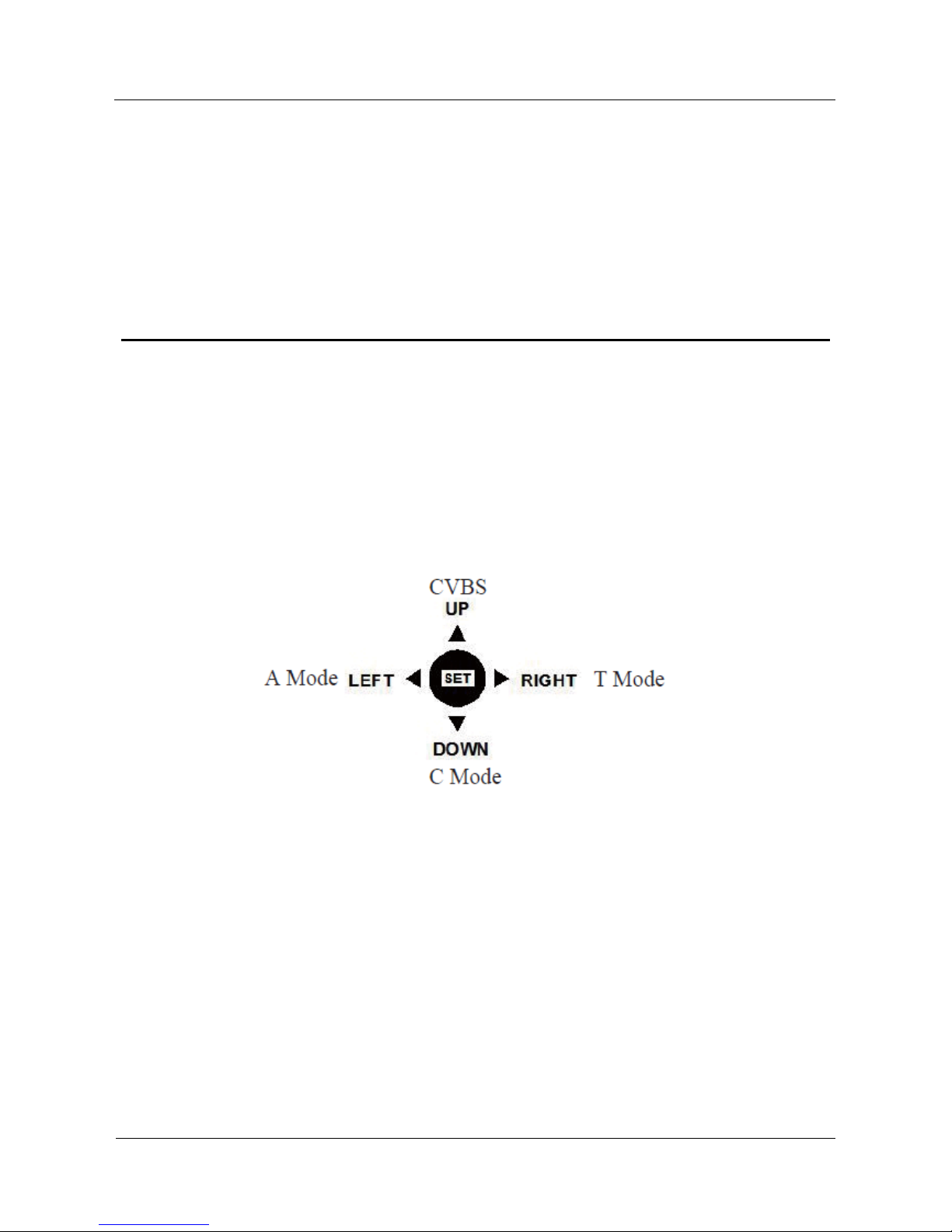
If your camera has four arrow buttons and one SET button, you can use the buttons to operate
the OSD main menu. Figure 1-2 shows the five buttons.
Figure 3-1 Five-button layout
The buttons have the following functions :
SET: Press this button to open the OSD main menu or end setup.
UP/DOWN: Press the two buttons to select the upper or lower menu.
LEFT/RIGHT: Press the two buttons to select different modes.
Press and hold the LEFT button for 5s to switch to AHD mode for output of the 1080P
AHD signal.
Press and hold the RIGHT button for 5s to switch to TVI mode for output of the 1080P
TVI signal.
Press and hold the UP button for 5s to switch to CVBS mode for output of the 960H
analog signal.
Press and hold the DOWN button for 5s to switch to CVI mode for output of the 1080P
CVI signal.
Operation Guide
3 OSD Main Menu
2
----End
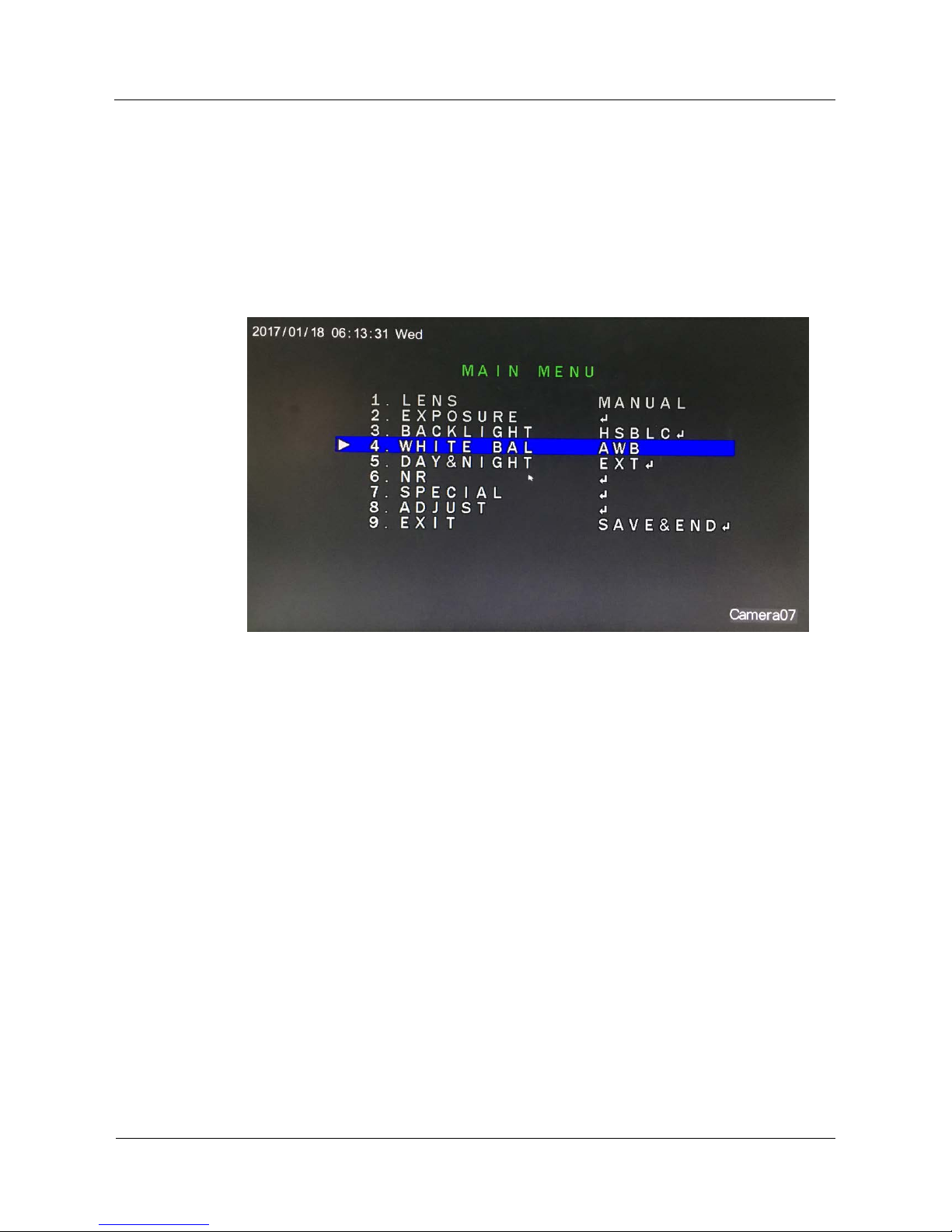
3.2 OSD Main Menu Interface
The OSD main menu interface includes LENS, EXPOSURE, BACKLIGHT, WHITE BAL,
DAY&NIGHT, NR, SPECIAL, and ADJUST, as shown in Figure 1-3.
Figure 3-2 OSD main menu interface
----End

Operation Guide
4 OSD Setting
3
4 OSD Setting
4.1 LENS
You can set LENS to MANUAL or DC.
Procedure
Step 1 Press the UP or DOWN button to select LENS.
Step 2 Press the LEFT or RIGHT button to set LENS to MANUAL or DC. The default value is
MANUAL.
----End
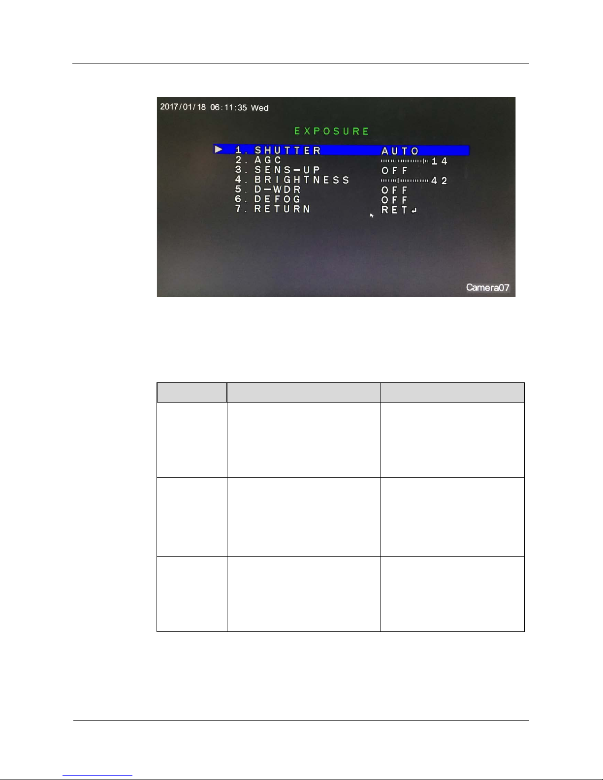
4.2 EXPOSURE
Exposure is intended to adjust image brightness by setting parameters such as aperture,
shutter, and gain. The EXPOSURE interface includes SHUTTER, AGC, SENS-UP,
BRIGHTNESS, D-DWR, and DEFOG.
Procedure
Step 1 Press the UP or DOWN button to select EXPOSURE.
Step 2 Press the OK button to ope n the EXPOSURE interface, as shown in Figure 2-1.
Operation Guide
4 OSD Setting
4
Figure 4-1 EXPOSURE interface
Step 1 Set exposure parameters.
Table 2-1 lists the exposure parameters.
Table 4-1 Exposure parameters
Parameter Meaning Setup
SHUTTER
This parameter is used to adjust
shutter manually for the desired
image brightness. The greater the
shutter, the brighter the image,
given that aperture and gain remain
unchanged.
[Setting method]
Press the LEFT or RIGHT
button.
[Default value]
AUTO
AGC
This parameter is used to adjust
image brightness and noise (two
factors that affect image quality).
The greater the gain, the brighter the
image and the higher the noise level.
Value range: 0–15
[Setting method]
Press the LEFT or RIGHT
button.
[Default value]
14
SENS-UP
At low illuminance, the sensor
triggers frame reduction and the
exposure time is prolonged to
increase image brightness and
reduce the noise level.
[Setting method]
Press the LEFT or RIGHT
button.
[Default value]
OFF

Operation Guide
4 OSD Setting
5
Parameter Meaning Setup
BRIGHTNESS
This parameter is used to adjust
image brightness.
Value range: 0–100
[Setting method]
Press the LEFT or RIGHT
button.
[Default value]
42
D-WDR
Overexposure or missing dark
details may occur when areas of low
brightness and high brightness
coexist in the same image. You can
set D-WDR to ON to enhance dark
areas while tuning down bright
areas for improved effect.
[Setting method]
Press the LEFT or RIGHT
button.
[Default value]
OFF
DEFOG
You can set this parameter to ON to
obtain images with enhanced
transparency in foggy environments.
[Setting method]
Press the LEFT or RIGHT
button.
[Default value]
OFF
Step 2 Press the UP or DOWN button to select RETURN.
Step 3 Press the LEFT or RIGHT button to select RETURN. The OSD setup interface is displayed.
Select SAVE&END to save the settings and exit the OSD setup interface.
----End
4.3 BACKLIGHT
You can set BACKLIGHT to HSBLC, BLC, or OFF.
Procedure
Step 1 Press the UP or DOWN button to select BACKLIGHT.
Step 2 Press the LEFT or RIGHT button to select a backlight mode. The options are HSBLC,
BLC, and OFF. The default value is OFF.
----End
4.3.1 HSBLC
You can select HSBLC to enable highlight compensation to make the target look clearer
when the backlight is too strong.
Step 1 Set BACKLIGHT to HSBLC and press the OK button to open the HSBLC interface, as
shown in Figure 2-2.
 Loading...