

Eneo KBD-2USB User Manual

EN
User Manual
System Keyboard with 3-Axis,
Joystick, Jog Shuttle, USB,
RS-485, 12VDC,
KBD-2USB
ii
WARNING AND CAUTION
WARNING
TO REDUCE THE RISK OF FIRE OR ELECTRIC SHOCK, DO NOT EXPOSE THIS PRODUCT
TO RAIN OR MOISTURE.
DO NOT INSERT ANY METALLIC OBJECT THROUGH VENTILATION GRILLS.
CAUTION
Explanation of Graphical Symbols
The lightning flash with arrowhead symbol, within an equilateral triangle, is intended to alert the
user to the presence of uninsulated “dangerous voltage” within the prod uc t’s enclosure that may
be of sufficient magnitude to constitute a risk of electric shock to persons.
The exclamation point within an equilateral triangle is intended to alert the user to the presence of
important operating and maintenance (servicing) instructions in the literature accompanying the
product.
CAUTION
RISK OF EXPLOSION IF B ATTERY IS REPLACED
BY AN INCORRECT TYPE.
DISPOSE OF USED BATTERIES ACCORDING
TO THE INSTRUCTIONS

iii
FCC COMPLIANCE STATEMENT
CE COMPLIANCE STATEMENT
This device complies with Part 15 of the FCC Rules. Operation is subject to the following two
conditions: (1) this device may not cause harmful interference, and (2
) this device must
accept any interference received, including interference that may cause undesired operation.
FCC INFORMATION :
This equipment has been tested and found to comply with the limits
for a Class A digital device, pursuant to Part 15 of the
FCC Rules. These limits are designed
to provide reasonable protection against harmful interference when the equipment is
operated in a commercial environment. This equipment generates, uses, and can radiate
radio frequency energy and, if not installed and
used in accordance with the instruction
manual, may cause harmful interference to radio communications. Operation of this
equipment in a residential area is likely to cause harmful interference in which case the user
CAUTION :
Changes or modifications not expressly approved by the party responsible for
compliance could void the user’s authority to operate the equipment.
WARNING
THIS IS A CLASS A PRODUCT. IN A DOMESTIC EN VIRONMENT THIS PROD UCT MAY CAUSE
RADIO INTERFERENCE IN WHICH CASE THE USER MAY BE REQUIRED TO TAKE
ADEQUATE MEASURES.
This Class A digital apparatus complies with Canadian ICES-003.
Cet appareil numérique de la classe A est conforme à la norme NMB-003 du Canada.

iv
IMPORTANT SAFEGUARDS
1. Read these instructions.
2. Keep these instructions.
3. Heed all warnings.
4. Follow all instructions.
5. Do not use this apparatus near water.
6. Clean only with dry cloth.
7. Do not block any ventilation openings. Install in accordance with the
manufacturer’s instructions.
8. Do not install near any heat sources such as radiators, heat registers, stoves, or
other apparatus (incl ud i ng amplifiers) that produce heat.
9. Do not defeat the safety purpose of the polarized or grounding-type plug. A
polarized plug has two blades with one wider than the other. A grounding type
plug has two blades and a third grounding prong. The wide blade or the third
prongs are provided for your safety. If the provided plug does not fit into your
outlet, consult an electrician for replacement of the obsolete outlet.
10. Protect the power cord from being walked on or pinched particularly at plugs,
convenience receptacles, and the point where they exit from the apparatus.
11. Only use attachments/accessories specified by the manufacturer.
12. Use only with the cart, stand, tripod, bracket, or table specified
by the manufacturer, or sold with the apparatus. When a cart is
used, use caution when moving the cart/apparatus combination to
avoid injury from tip-over.
13. Unplug this apparatus during lightning storms or when unused
for long periods of time.
14. Refer all servicing to qualified service personnel. Servicing is required when the
apparatus has been damaged in any way, such as power-supply cord or plug is
damaged, liquid has been moisture, does not operate normally, or has been
dropped.
15. CAUTION – THESE SERVICING INSTRUCTIONS ARE FOR USE BY
QUALIFIED SERVICE PERSONNEL ONLY. TO REDUCE THE RISK OF
ELECTRIC SHOCK DO NOT PERFORM ANY SERVICING OTHER
THAN THAT CONTAINED IN THE OPERATING INSTRUCTIONS
UNLESS YOU QRE QUALIFIED TO DO SO.
16. Use satisfy clause 2.5 of IEC60950-1/UL60950-1 or Certified/Listed
Class 2 power source only.

v
Table of Contents
Chapter 1 — Introduction...............................................................................................................................1
1.1 Features ..............................................................................................................................................1
1.2 Package Contents ...............................................................................................................................1
1.3 Required Installation Tools ..................................................................................................................1
1.4 Connectors ..........................................................................................................................................2
Chapter 2 — Installation and Config u ration ................................................................................................3
2.1 USB Configuration of Fastrax Dome System ......................................................................................3
2.2 Basic Configuration of Fastrax Dome System ....................................................................................4
2.3 Configuration with DVR. ......................................................................................................................5
2.4 Configuration of Mas ter and Slave Keyboards. ...................................................................................6
2.5 T ermination. .........................................................................................................................................9
2.6 Dip Switch Settings. ......................................................................................................................... 10
Chapter 3 — Keyboard Setup ..................................................................................................................... 11
3.1 Configuration .................................................................................................................................... 11
Change User Password .................................................................................................................. 11
Change Administrator Password ..................................................................................................... 12
3.2 Network ............................................................................................................................................ 12
Baud Rate ....................................................................................................................................... 12
Com Ports ....................................................................................................................................... 12
USB ................................................................................................................................................. 13
Set Slave Kbd .................................................................................................................................. 13
Slave KBD Unit ................................................................................................................................ 14
3.3 Camera ............................................................................................................................................. 14
3.4 Time / Date ....................................................................................................................................... 14
3.5 ALARM ............................................................................................................................................. 15
3.6 LCD .................................................................................................................................................. 16
3.7 DATA BANK ...................................................................................................................................... 16
3.8 INITIALIZATION ............................................................................................................................... 17
3.9 INFORMATION ................................................................................................................................. 17
3.10 HOLD TIME .................................................................................................................................... 17
Chapter 4 — Slave Keyboard Setup .......................................................................................................... 18
Chapter 5 — Install with DVR Series.......................................................................................................... 19
5.1 Install with Standalone DVR Series .................................................................................................. 19
Chapter 6 — Install with NVR/Hybrid DVR/Virtual Matrix ........................................................................ 22
Installing System Keyboard .................................................................................................................... 22

vi
Chapter 7 — Operation................................................................................................................................ 27
7.1 Keyboard Lock/Unlock (Hidden command) ...................................................................................... 27
7.2 Summary of Keyboard Controls ....................................................................................................... 27
7.2.1 Keys for Dome camera .......................................................................................................... 28
7.2.2 Keys for DVR [DVR1-4, PC-DVR] .......................................................................................... 29
7.2.3 Example of Key operation in PC-DVR ................................................................................... 31
7.4 DVR5 protocol for the DVR for the version 3.1.0 and over .............................................................. 32
Appendix A - USB Control Key ................................................................................................................... 37
Appendix B- Short Cut Key......................................................................................................................... 39
Appendix C- Trouble Shooting ................................................................................................................... 41
Appendix D -SPECIFICATION ..................................................................................................................... 42
MEMO ............................................................................................................................................................ 44

Chapter 1 — Introduction
1.1 Features
This keyboard controller is capable of controlling d ome cameras and pr oviding remote contr ol functions
for a variety of external switching devices such as Multiplexers, Digital Video Recorders etc.
A combination of 4 Keyboard controllers and 5 Multiplexers comprises a small matrix system (64x4) using
its remote control functions and programmable macro functions.
Variable speed control joystick with zoom controlling handle.
Program and recall progra mmed preset positions, auto scan, tour, pattern, from the selecte d dome
camera.
Two levels of password are supported for higher security, administrator and user.
Up to 254 dome cameras controllable including 64 dome cameras with Alarm mode.
USB Interface Control.
Up to 3 slave of the same type keyboard controllers can be connected to the master keyboard.
Battery backed-up clock displays real time on the LCD screen.
Up to two dome cam eras’ programmed data can be downloaded to n onvolatile memory space, and
later uploaded to the new dome camera.
The dome with the ID up to 3999 can be controlled.
Scan range option: 32, 254, 3999.
1.2 Package Contents
The package contains the following.
Description Q’ty
Keyboard controller 1
CD(Instruction manual, NC Titanium and Driver) 1
USB Cable 1
12VDC Power supply (SMPS) 1
Power Cord 1
1.3 Required Installation Tools
No special tools are required to install the KBD controller. Refer to the installation manuals for the other
items that make up part of your system.
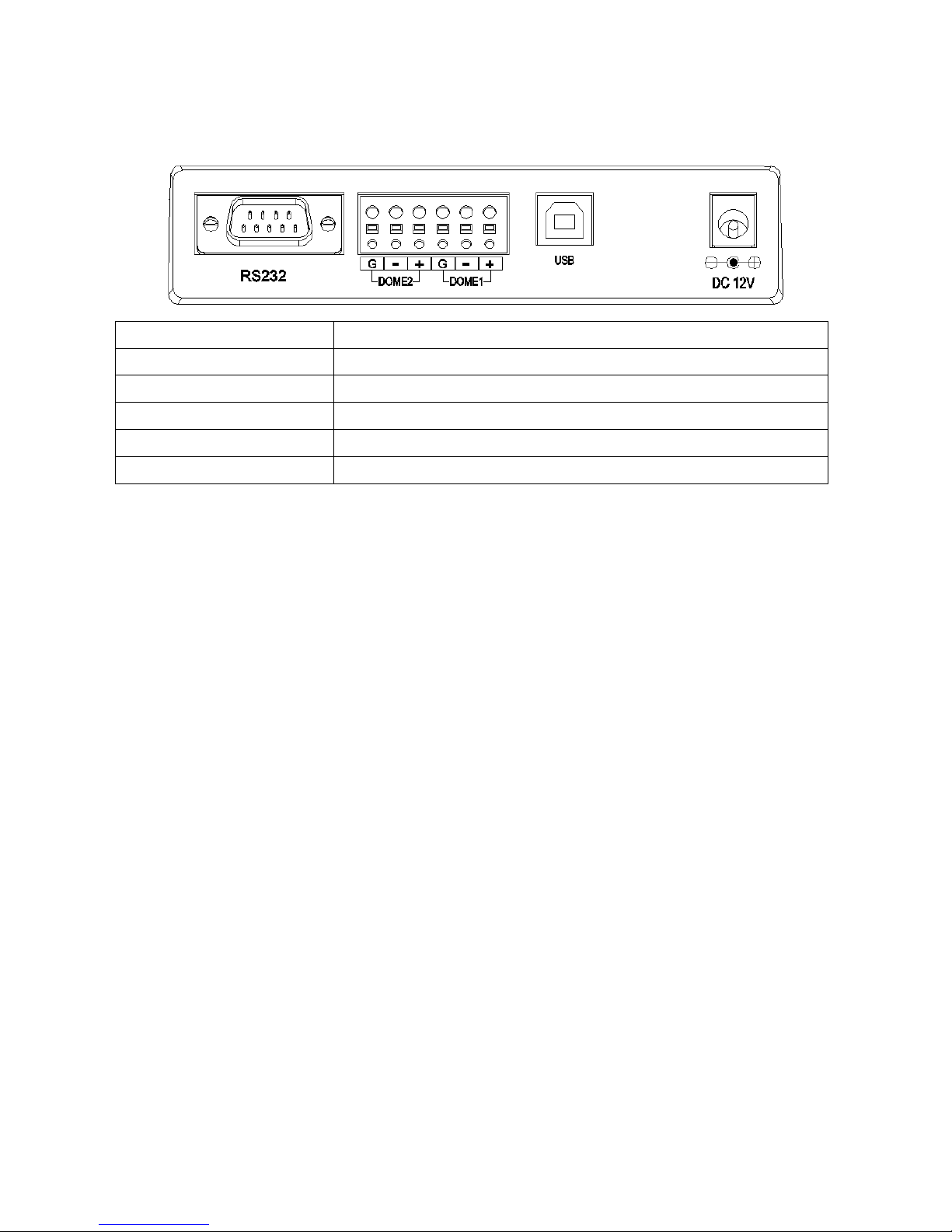
1.4 Connectors
CONNECTOR USAGE
RS232
RS232:DVR/UPGRADE
DOME2
RS485:DOME/DVR/MULTIPLEXER/SLAVE KEYBOARD
DOME1
RS485:DOME
USB
FOR USB TO THE PC
DC12V
FOR POWER SUPPLY
Chapter 2 — Installation and Configuration
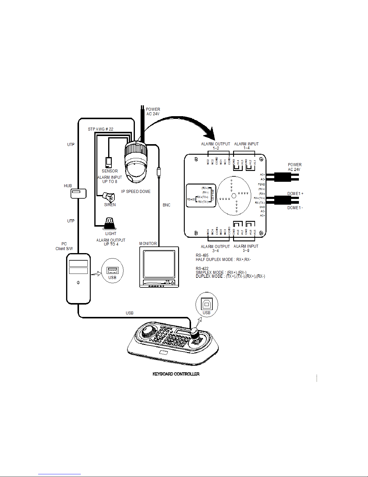
2.1 USB Configuration of Fastrax Dome System
Figure 1 – Basic installation diagram
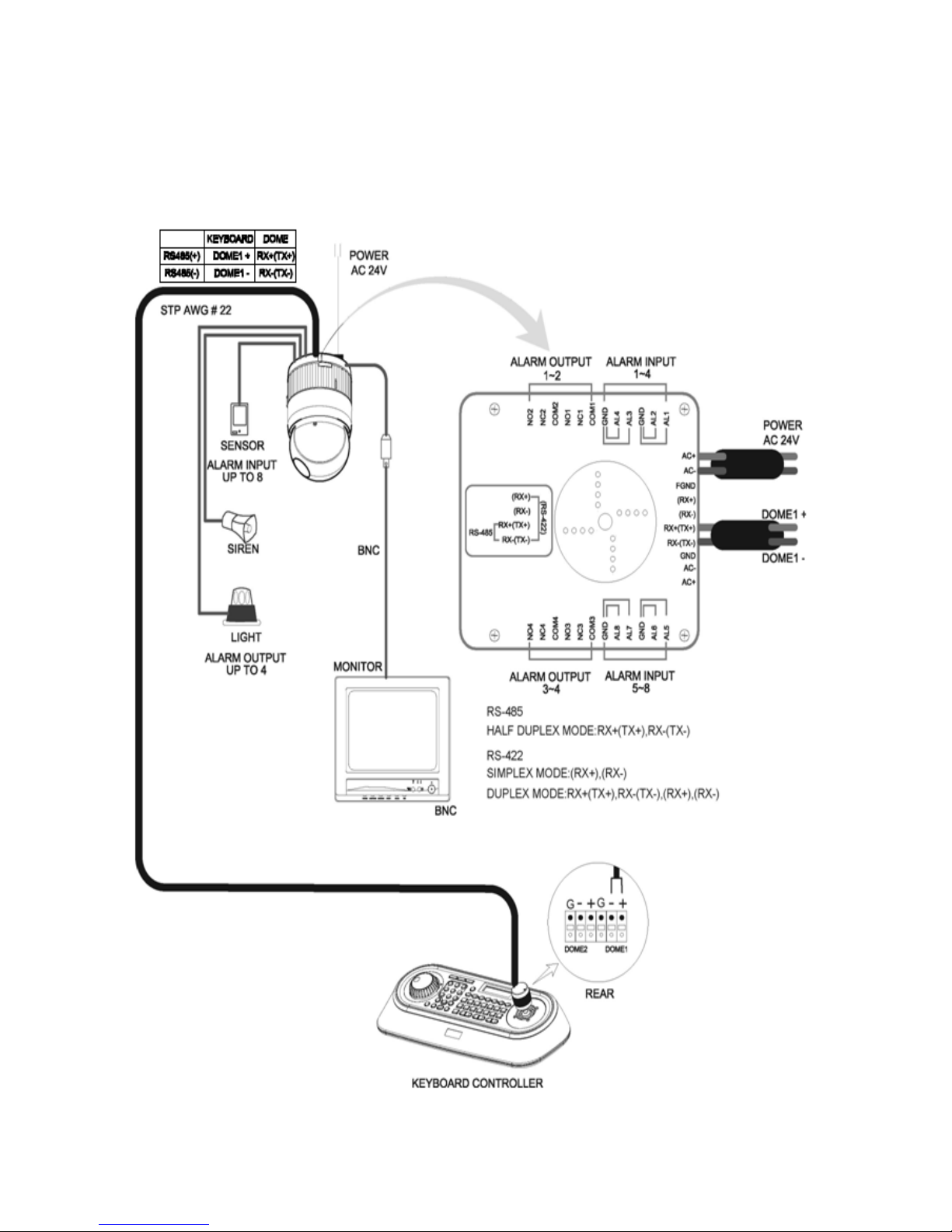
2.2 Basic Configuration of Fas tr ax Dome System
Figure 2 – Basic installation diagram
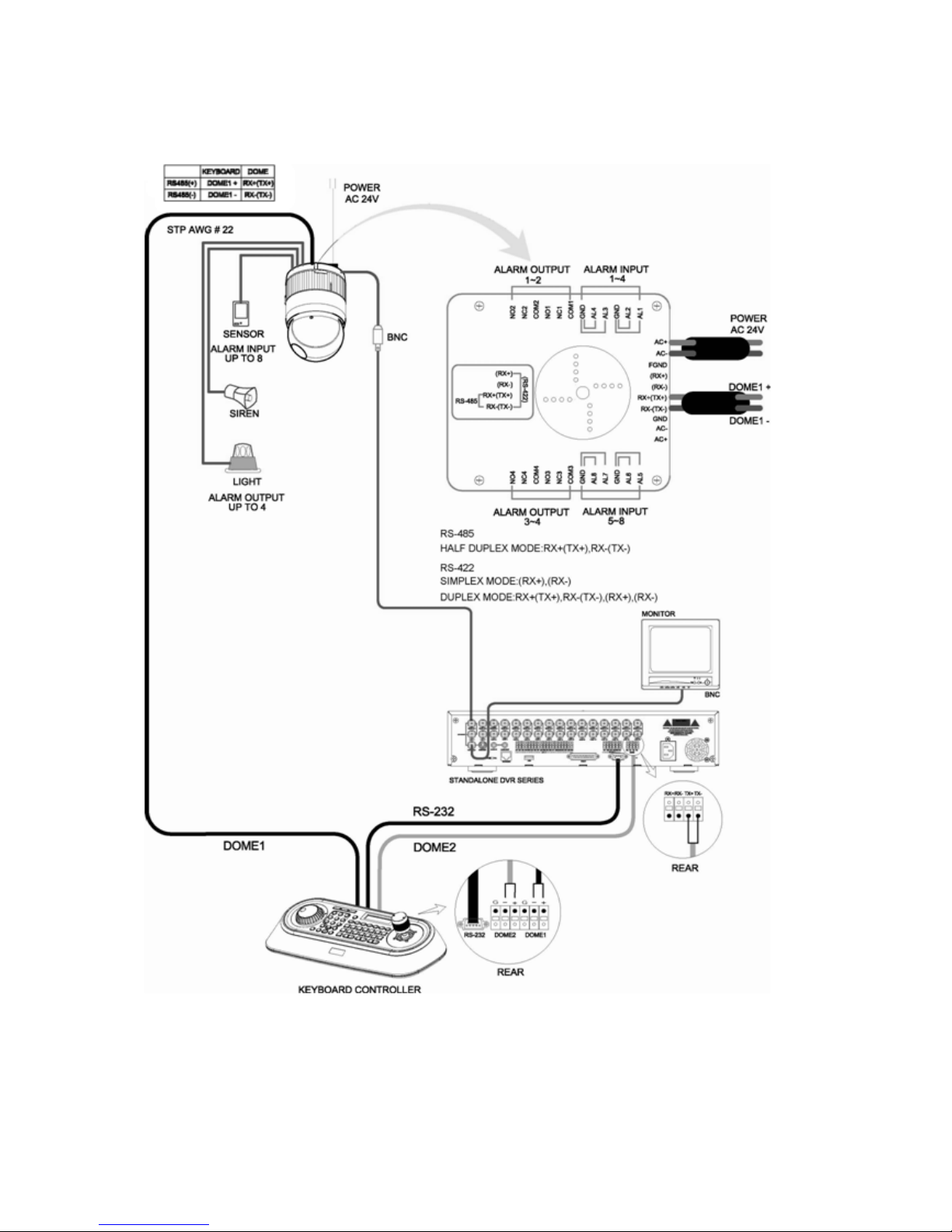
2.3 Configuration with DVR.
Figure 3 –installation diagram with DVR
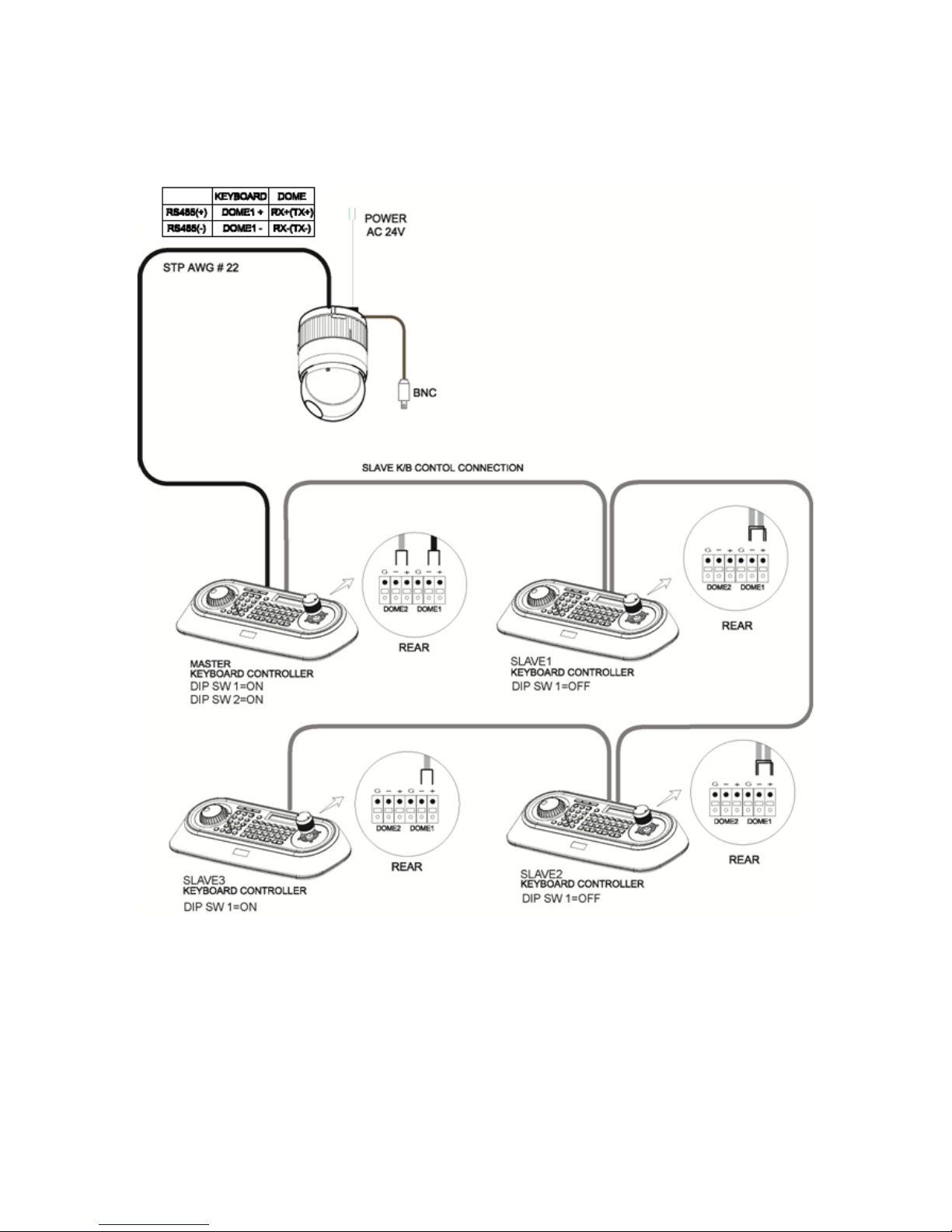
2.4 Configuration of Master and Slave Keyboar d s.
Figure 4 –Master and Slave keyboard connection
Note: Connect the DOME1 port of all slave keyboards to the DOME2 port of the master keyboard
and set the DIP SW 1 and 2 as the figure above. This is not supported in “USB ON”.
Master Keyboard Setting
Slave Keyboard Setting
1. 1. Dip switch the of S1 is "ON"
2. 2.
3.
th
8
Network
1.Baud Rate
2.Com Ports
3.USB : ON
4.Mux Config
5.Set Slave KBD
Save and Exit
Com Ports
1.Dome1 : Dome
2.Dome2 : KBDTRI(or KBDDUP)
3.RS232 : Don’t care
Save and Exit
Set Slave KBD
1.Slave KBD: ON
2.MUX Cont : ON
3.DVR Cont : ON
4.Dome Menu: ON
5.Slave KBD Unit
Network
1.Keyboard ID : 01
2.BPS : 9600
Save and Exit

4.
NOTE : Slave keyboards are not supported in
“USB ON”
Slave KBD Unit
1.Slave ID1: ON
2.Slave ID2: OFF
3.Slave ID3: OFF
Save and Exit
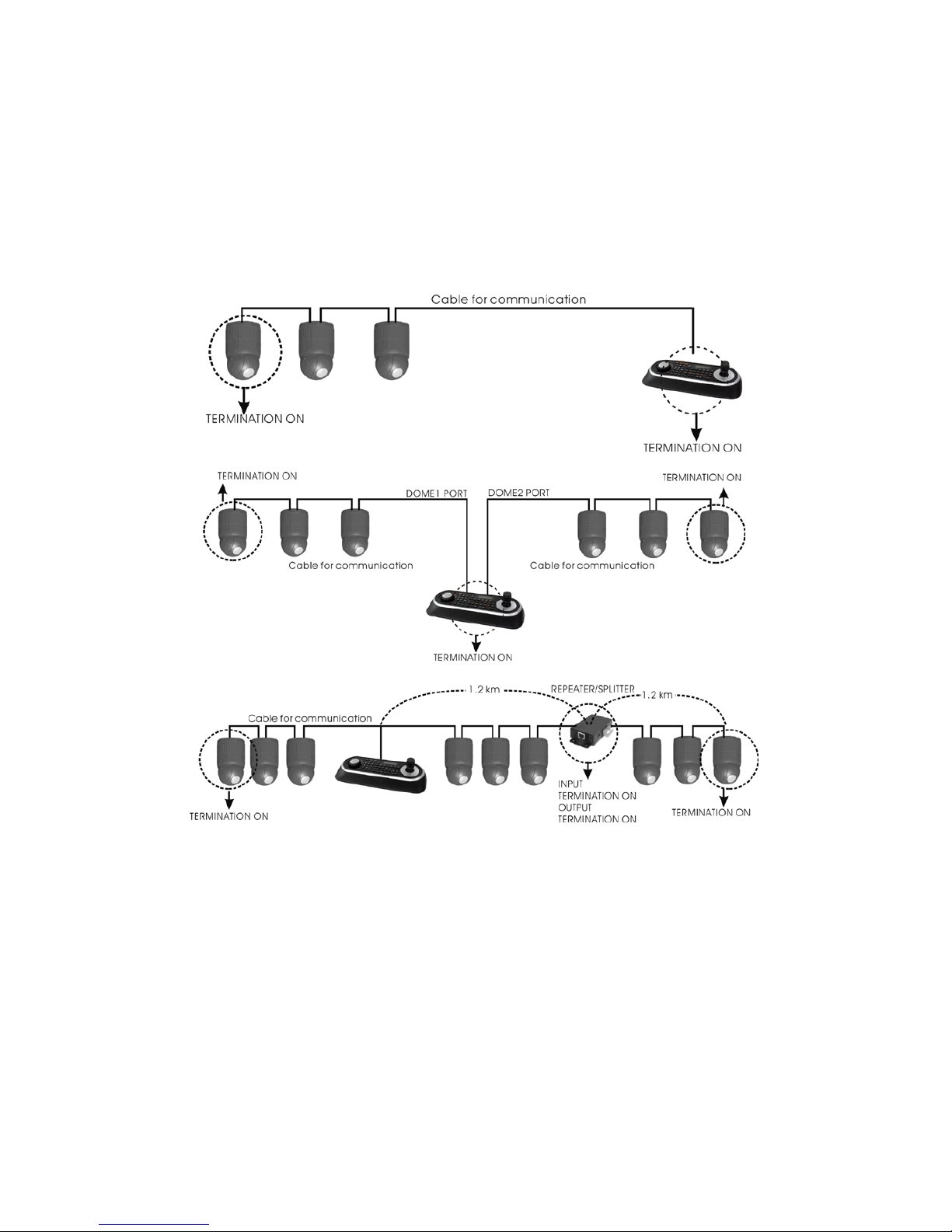
2.5 Termination.
The first and last devices in an installation (dome and keyboard controller) must have the data line
terminated by setting the DIP switch. Without proper termination, there is potential for control signal
errors. Total length of the cable for communication should not exceed 4000ft (1 .2Km).
Refer to Figure 6 for setting the dome camera and keyboard controller termination.
Figure 5 – Termination
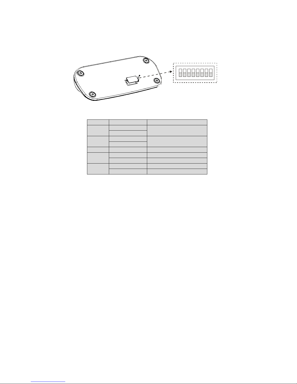
2.6 Dip Switch Settings.
Termination and Master/Slave: Set the switches according to your configuration.
ON
9J
S1
1 2 3 4 5 6 7 8
Figure 7 – Keyboard DIP Switches
NO
SETTING
DESCRIPTION
1
ON
Dome1 Ter mination
OFF
2
ON
Dome2 Ter mination
OFF
3~6
OFF
Reserved
7
ON
Download On
OFF
Download Off
8
ON
Slave
OFF
Master
Table 1 - S1 Switch Setting
 Loading...