

Eneo KBD-2 Installation And Operating Manual
1
Installation and Operating Manual
System Keyboard with Joystick and Jog Shuttle, 12VDC/230VAC
KBD-2

2
Contents
Safety Instructions ....................................................................................................................................................................................................................3
1. Introduction ...................................................................................................................................................................................................................
3
1.1 Features ..............................................................................................................................................................................................................3
1.2 Package Contents ................................................................................................................................................................................................4
1.3 Required Installation Tools ....................................................................................................................................................................................4
1.4 Connectors ..........................................................................................................................................................................................................4
2. Installation and Configuration .........................................................................................................................................................................................
5
2.1 Basic Configuration of Fastrax Dome System .......................................................................................................................................................5
2.2 Configuration with DVR ........................................................................................................................................................................................6
2.3 Configuration with MUX .......................................................................................................................................................................................7
2.4 Configuration of Master and Slave Keyboards ......................................................................................................................................................8
2.5 Termination ..........................................................................................................................................................................................................9
2.6 Dip Switch Setting .............................................................................................................................................................................................10
2.7 Multiplexer Configuration ...................................................................................................................................................................................10
3. Keyboard Setup ...........................................................................................................................................................................................................
11
3.1 Configuration .....................................................................................................................................................................................................11
3.2 Network .............................................................................................................................................................................................................12
3.3 Camera ..............................................................................................................................................................................................................19
3.4 Time / Date ........................................................................................................................................................................................................19
3.5 ALARM ...............................................................................................................................................................................................................20
3.6 LCD ...................................................................................................................................................................................................................20
3.7 DATA BANK ........................................................................................................................................................................................................20
3.8 INITIALIZATION ................................................................................................................................................................................................... 21
3.9 HOLD TIME.........................................................................................................................................................................................................21
4. Slave Keyboard Setup ..................................................................................................................................................................................................
21
5. Install with DVR Series .................................................................................................................................................................................................
22
5.1 Install with Standalone DVR Series .....................................................................................................................................................................22
5.2 Install with PC DVR Series ..................................................................................................................................................................................25
6. Operation .....................................................................................................................................................................................................................
28
6.1 Keyboard Lock/Unlock (Hidden command) .........................................................................................................................................................28
6.2 Controlling Multiplexer .......................................................................................................................................................................................28
6.2.1 Selecting Multiplexer ............................................................................................................................................................................28
6.2.2 Dome Camera Selection .......................................................................................................................................................................28
6.3 Summary of Keyboard Controls ..........................................................................................................................................................................29
6.3.1 Keys for Dome Cameras .......................................................................................................................................................................30
6.3.2 Keys for Multiplexer .............................................................................................................................................................................. 31
6.4 DVR5 protocol for the DVR for the version 3.1.0 and over Installation of the DVR5 protocol when one DVR is used. ............................................35
6.4.1 Operation of the keyboard ....................................................................................................................................................................36
6.4.2 Installation of DVR5 protocol when may DVR is use ..............................................................................................................................37
7. Troubleshooting ...........................................................................................................................................................................................................40
8. Short Cut Key ...............................................................................................................................................................................................................
41
9. Specifications ..............................................................................................................................................................................................................
42
10. Dimensional Drawings .................................................................................................................................................................................................
43
Betriebsanleitung
Installation and Operating Instructions
Mode d’emploi
Instrucciones de manejo
www.videor.com
⇒

3
1. Introduction
1.1 Features
This keyboard controller is capable of controlling dome cameras and providing remote control functions
for a variety of external switching devices such as Multiplexers, Digital Video Recorders etc.
A combination of 4 Keyboard controllers and 5 Multiplexers comprises a small matrix system (64x4) using
its remote control functions and programmable macro functions.
• Programming and Control of Camera Series: Fastrax and Minitrax
• For DVR Series DLR1.2, DLR3/4, DTR, DIR and DPR
• Supports up to 508 Cameras
• Joystick Control of PTZ Functions
• Programmable Sequences / Patterns
• Preset Position and Pattern Control
• Auto and Random Scanning
• Auxiliary Operation
• Master / Slave Operating (up to 3 Slaves)
• RS-232/RS-485 Multi Protocol Interfaces
• 16x2 Lines LCD Display
Safety Instructions
• Read these safety instructions and the operation manual first before you install and commission the unit.
• Keep the manual in a safe place for later reference.
• Protect your unit from contamination with water and humidity to prevent it from permanent damage. Never switch the unit on when it gets wet.
Have it checked at an authorized service center in this case.
• Never operate the units outside of the specifications as this may prevent their functioning.
• Do not operate the unit beyond their specified temperature, humidity or power ratings. Operate the unit only at a temperature range of 0°C to +50°C
and at a humidity of max. 90%.
• To disconnect the power cord of the unit, pull it out by the plug. Never pull the cord itself.
• Pay attention when laying the connection cable and observe that the cable is not subject to heavy loads, kinks, or damage and no moisture can get in.
Do not attempt to disassemble the camera board from the dome.
• The warranty becomes void if repairs are undertaken by unauthorized persons. Do not open the camera housing.
• Maintenance and repair have to be carried out only by authorized service centers.
• Do not use strong or abrasive detergents when cleaning the dome. Use a dry cloth to clean the dome surface. In case the dirt is hard to remove, use a mild
detergent and wipe gently.
NOTE: This is a class A digital device. This digital device can cause harmful interference in a residential area; in this case the user may be
required to take appropriate corrective action at his/her own expense.
4
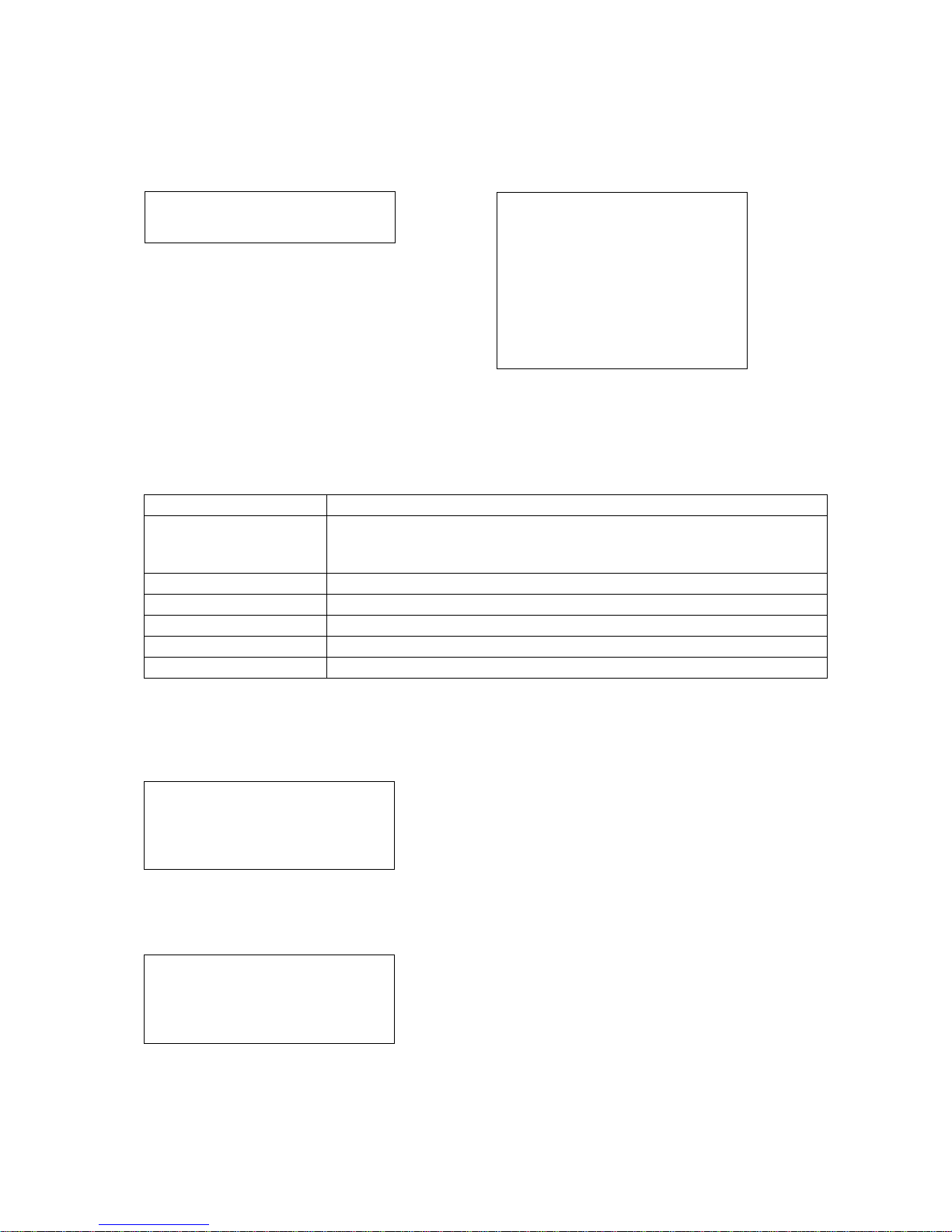
Multiplexer
up to 8
alarm inputs
up to 4
alarm
outputs
up to 254 cameras including 64 alarm modes
(Sensor)
(Siren)
(Flashing light)
DVR
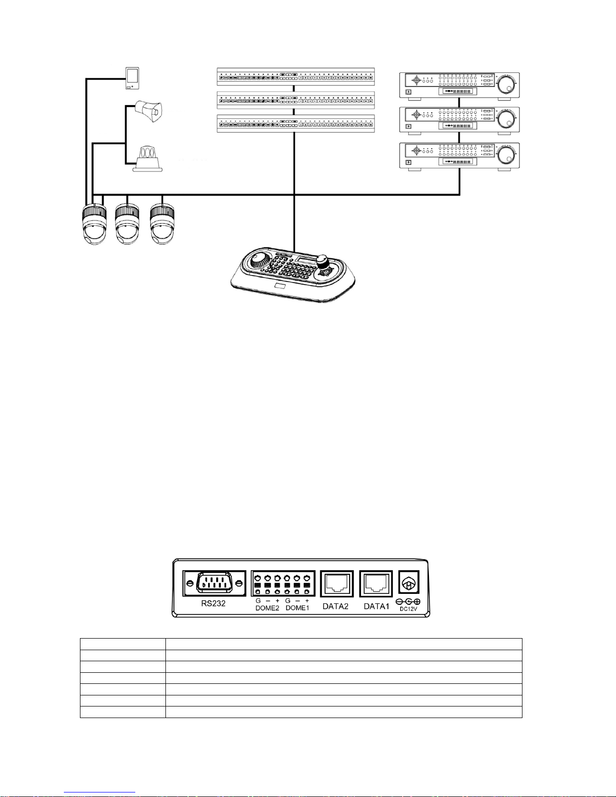
Figure 1: Typical System Configuration
1.2 Package Contents
The package contains the following:
1x Keyboard controller
1x Instruction manual
1x 12VDC Power supply (SMPS)
1x Power Cord
1.3 Required Installation Tools
No special tools are required to install the KBD controller. Refer to the installation manuals for the other items that make up part of your system.
1.4 Connectors
NOTE: Don’t connect the DATA1 PORT and DC12V PORT together.
Connector Usage
RS-232
RS-232: DVR / Upgrade
DOME2
RS-485: DOME / DVR / Multiplexer / Slave Keyboard
DOME1
RS-485: DOME
DATA2
For Junction Box only
DATA1
For Junction Box only
DC12V
For Power Supply
5
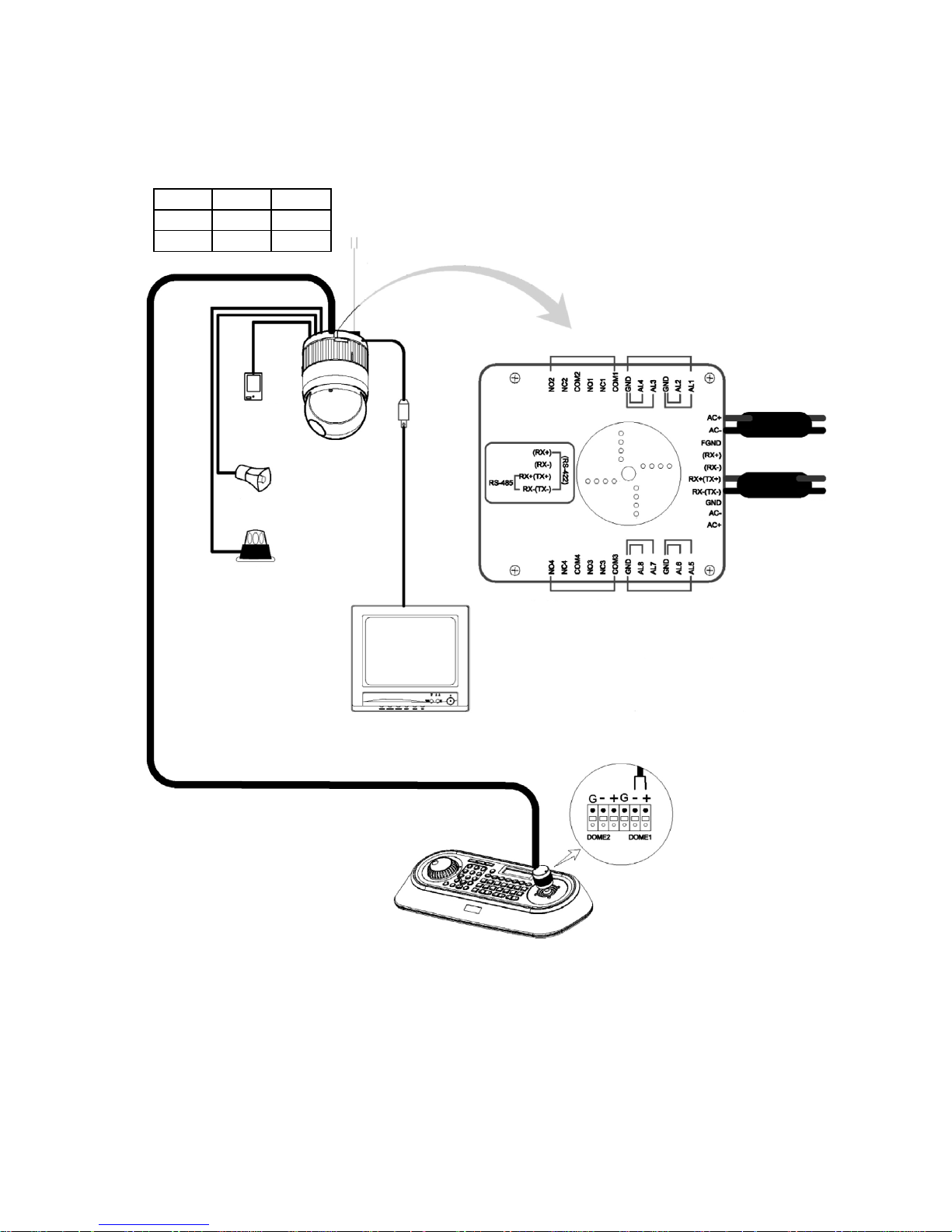
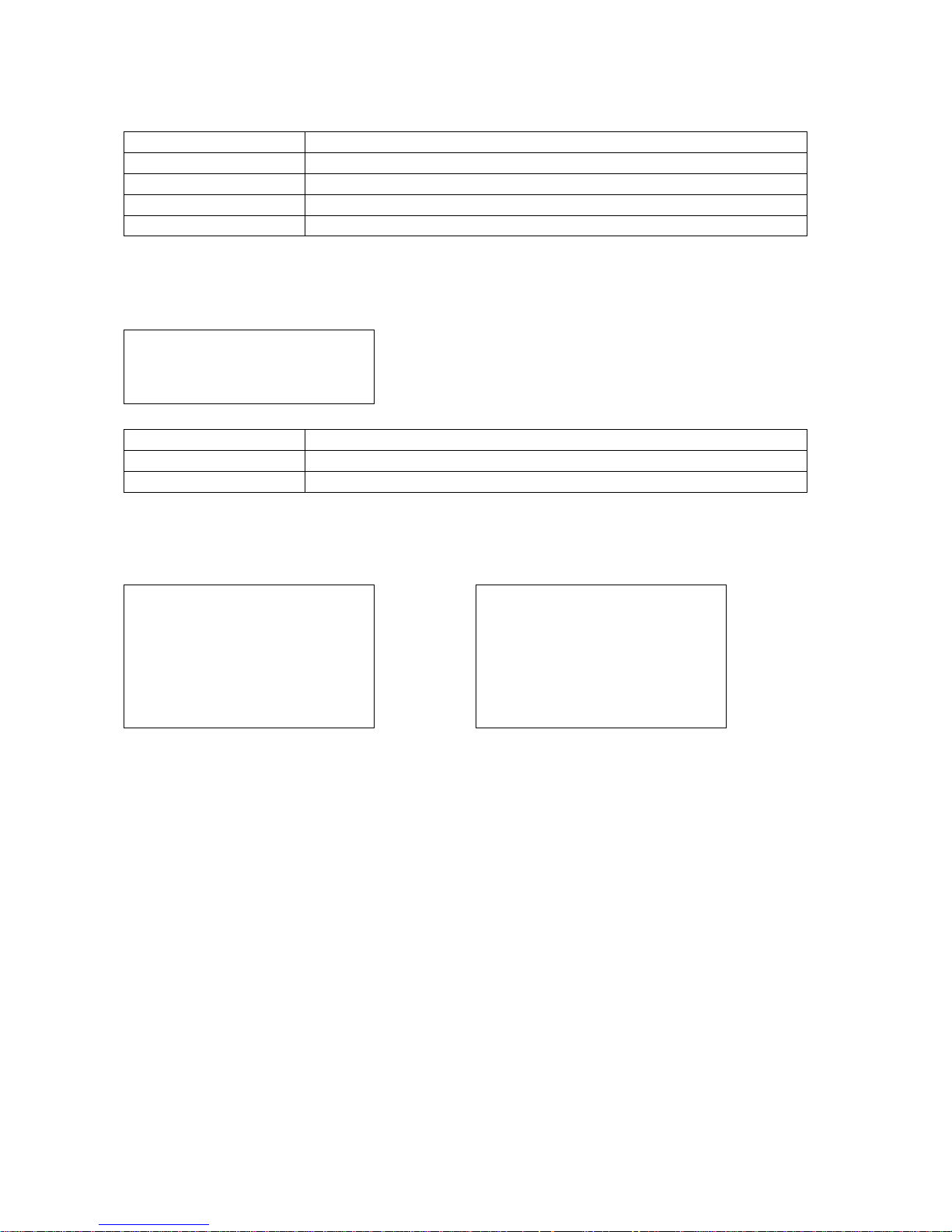
Figure 2: Basic installation diagram
STP AWG #22
Power 24VAC
Sensor
BNC
Monitor
Alarm input
up to 8
Siren
Light
Alarm output
up to 4
Rear
Keyboard controller
Alarm output 1-2
Alarm input 1-4
Power 24VAC
Dome 1 +
Dome 1 –
Alarm output 3-4 Alarm input 5-8
BNC
RS-485
Half Duplex Mode: RX+ (TX+), RX- (TX-)
RS-422
Simplex Mode: (RX+), (RX-)
Duplex Mode: RX+ (TX+), RX- (TX-), (RX+), (RX-)
J-Box Dome
RS-485(+) DOME 1 + RX+ (TX+)
RS-485(-) DOME 1 - RX- (RX-)
2. Installation and Configuration
2.1 Basic Configuration of Fastrax Dome System
6
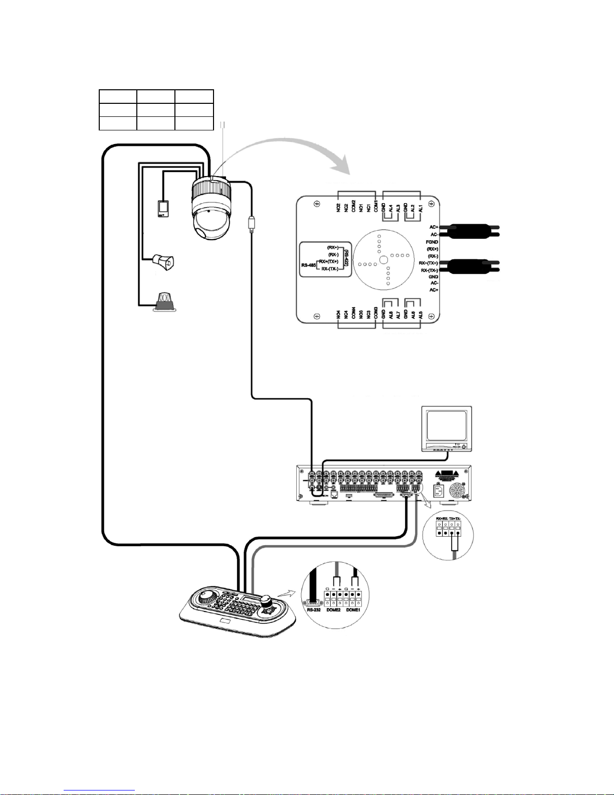
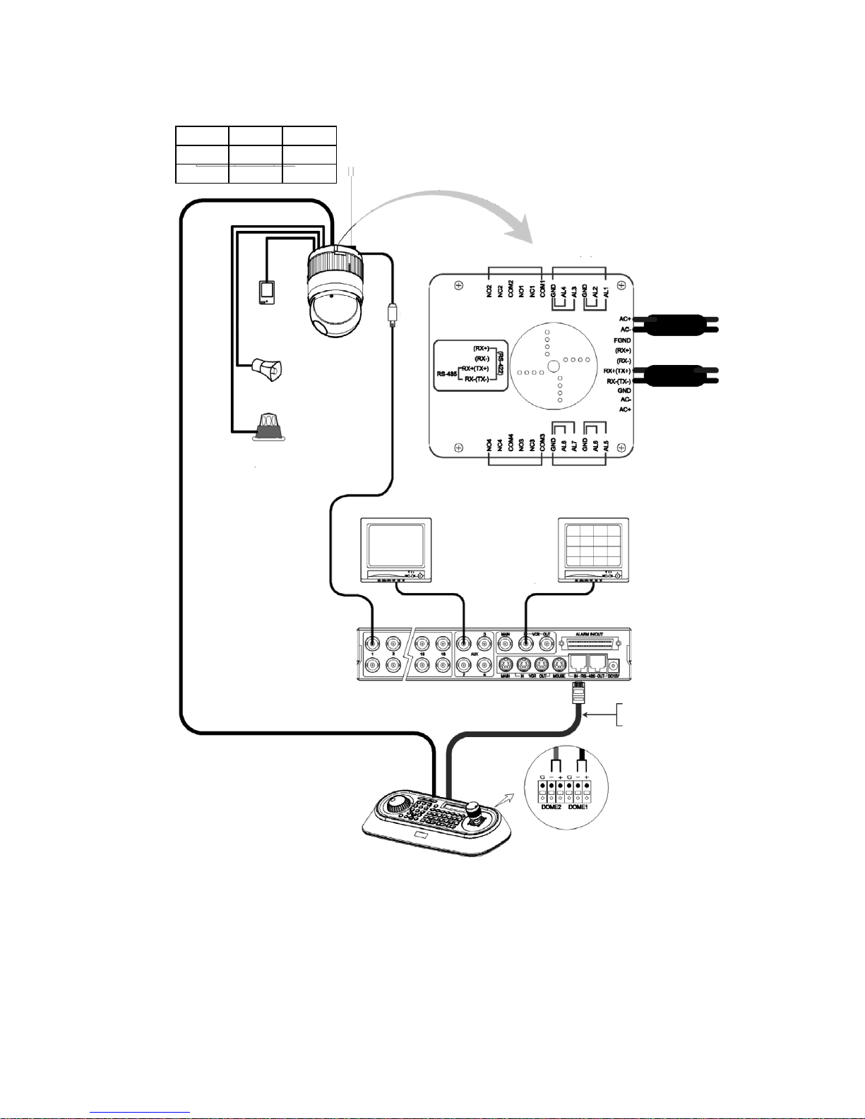
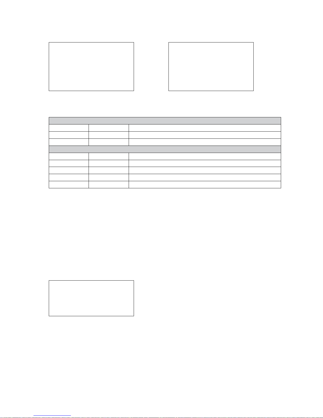
Figure 3: Installation diagram with DVR
STP AWG #22
Power 24VAC
Sensor
BNC
Monitor
Alarm input
up to 8
Siren
Light
Alarm output
up to 4
BNC
Rear
Keyboard controller
Alarm output 1-2
Alarm input 1-4
Power 24VAC
Dome 1 +
Dome 1 –
Alarm output 3-4 Alarm input 5-8
RS-485
Half Duplex Mode: RX+ (TX+), RX- (TX-)
RS-422
Simplex Mode: (RX+), (RX-)
Duplex Mode: RX+ (TX+), RX- (TX-), (RX+), (RX-)
J-Box Dome
RS-485(+) DOME 1 + RX+ (TX+)
RS-485(-) DOME 1 - RX- (RX-)
2.2 Configuration with DVR
7
Figure 4: Installation diagram with MUX
2.3 Configuration with MUX
STP AWG #22
Power 24VAC
Sensor
BNC
Main Monitor
Alarm input
up to 8
Siren
Light
Alarm output
up to 4
Rear
Keyboard controller
Alarm output 1-2
Alarm input 1-4
Power 24VAC
Dome 1 +
Dome 1 –
Alarm output 3-4 Alarm input 5-8
RS-485 (+) Pin No. 6
RS-485 (-) Pin No. 4
J-Box Dome
RS-485(+) DOME 1 + RX+ (TX+)
RS-485(-) DOME 1 - RX- (RX-)
Spot Monitor
BNC BNC
Multiplexer
DOME1 DOME2
8
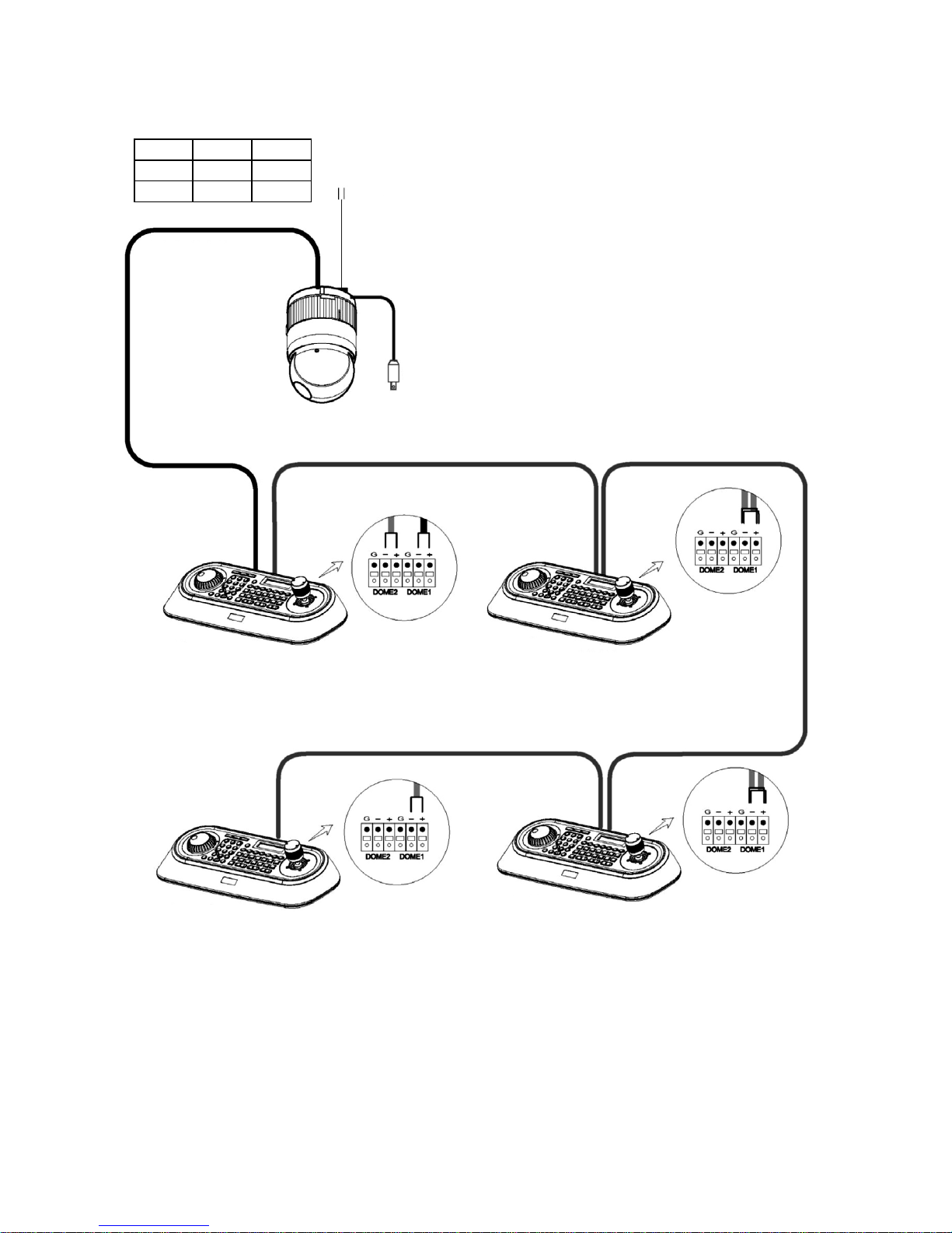
Figure 5: Master and Slave keyboard connection
NOTE: Connect the DOME1 port of all slave keyboards to the DOME2 port of the master keyboard and set the DIP SW 1 and 2 as the figure above.
2.4 Configuration of Master and Slave Keyboards
STP AWG #22
Power 24VAC
BNC
Slave K/B control connection
Rear
Master
Keyboard controller
DIP SW 1 = ON
DIP SW 2 = ON
DIP SW 8 = OFF
DOME 2: Protocol KBDDUP
J-Box Dome
RS-485(+) DOME 1 + RX+ (TX+)
RS-485(-) DOME 1 - RX- (RX-)
Rear
Slave3
Keyboard controller
DIP SW 1 = ON
DIP SW 8 = ON
Slave1
Keyboard controller
DIP SW 1 = OFF
DIP SW 8 = ON
Rear
Rear
Slave2
Keyboard controller
DIP SW 1 = OFF
DIP SW 8 = ON
9
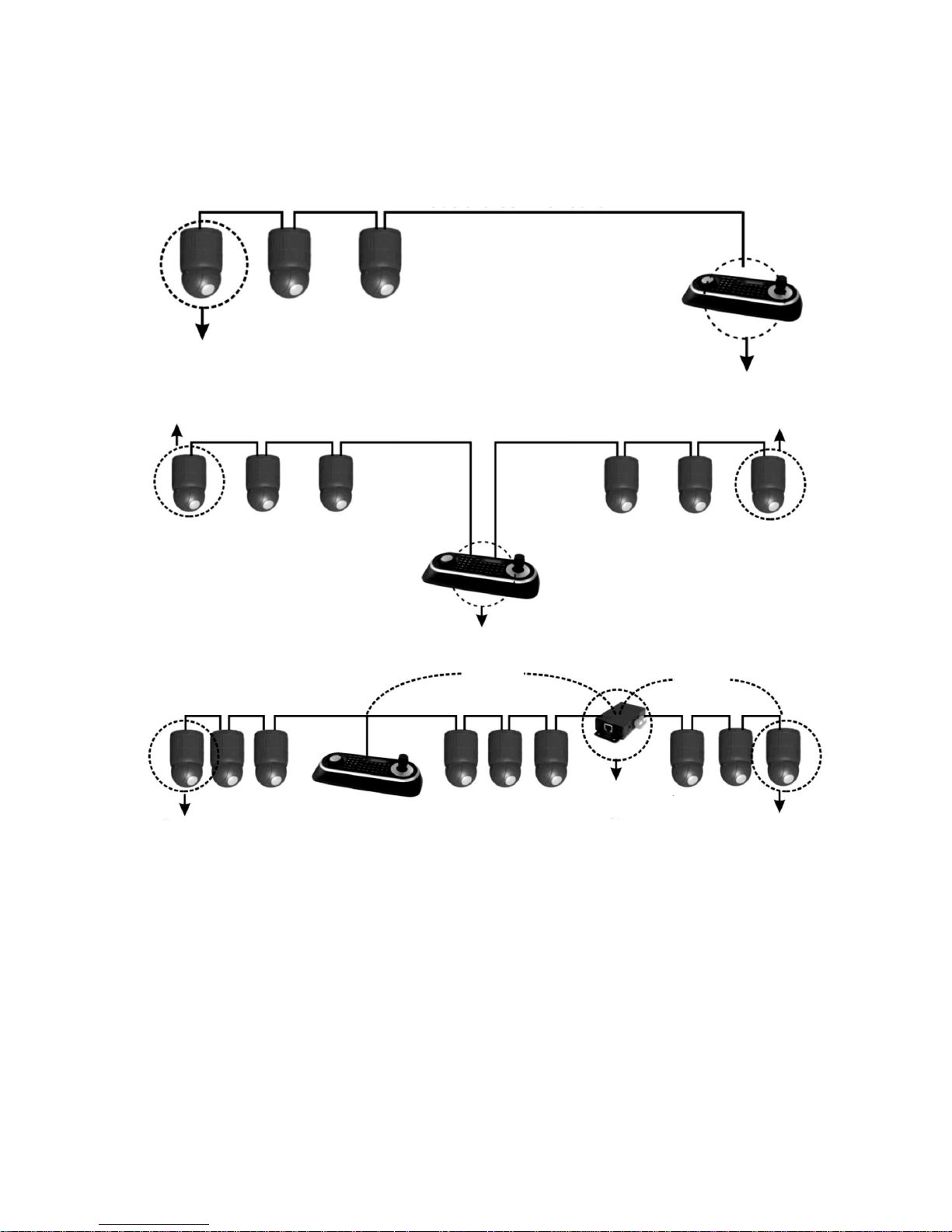
Figure 6: Termination diagram
2.5 Termination
The first and last devices in an installation (dome and keyboard controller) must have the data line terminated by setting the DIP switch.
Without proper termination, there is potential for control signal errors. Total length of the cable for communication should not exceed 1.2km.
Cable for communication
Termination ON
1.2km
Repeater/Splitter
Cable for communication
Input termination ON
Output termination ON
1.2km
Termination ON
Termination ON
Termination ON
Termination ON
Termination ON
Cable for communicationCable for communication
10
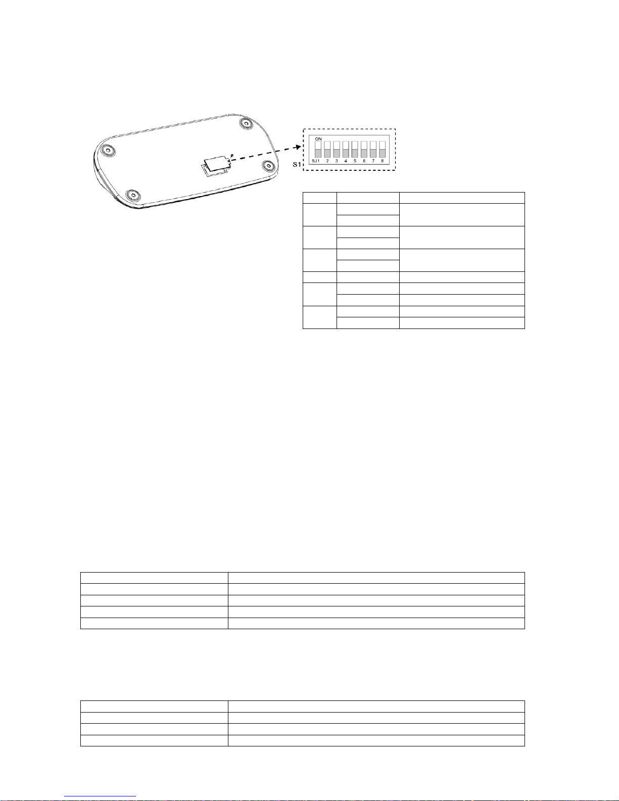
2.6 Dip Switch Setting
Termination and Master/Slave: Set the switches according to your configuration.
Figure 7: Keyboard DIP switches
2.7 Multiplexer Configuration
Duplex Setup:
NOTE: Multiplexers to be controlled by the keyboard controller require a new ROM version. The new multiplexer ROM accepts control
instructions from the keyboard controller. If your multiplexer ’s serial number is „M104xxxx” or higher, then it is ready to accept control
instructions. Alternately, you can check the status of your multiplexer by pressing the Menu key of the multiplexer and then selecting
item 9. If you see the „** Protocol” option line in the Communication Setup menu, your multiplexer has the new ROM, and you do not
need to replace the ROM. If your multiplexer has the old ROM version, contact your distributor on how to get new a ROM.
CAUTION: Before opening the multiplexer, make certain you are working on an antistatic work surface and that you are wearing a grounding wrist
strap. Also, be very careful to orient the ROM chip correctly and not bend any of the pins.
NOTE: Replace the multiplexer firmware with the new multiplexer ROM (U45) as follows; remove the top cover of the multiplexer, and locate the
ROM (U45). Before removing the ROM, note the orientation of the ROM. After removing the old ROM from the socket, insert the new ROM.
Be careful to orient the new ROM the same as the old ROM. (Refer to the Multiplexer instruction manual.)
Set the multiplexer functions as follows: (Press the Menu key of the multiplexer to enter the Unit Options menu.)
Unit options:
Unit number 001 (first Mux) or 002 (second Mux)
Communication type RS-485
Baud rate 9600 bps
PORT ON
** Protocol ** B (If you see this line, the multiplexer has the new ROM)
** The old ROM version does not show Protocol selection option.
Multiplexer alarm inputs will function normally, but the Dome controller has no way of knowing about alarms wired to the Multiplexer. If a Dome preset is
required for such an alarm, you must connect the same alarm input to both the multiplexer and Dome.
Triplex setup:
Unit setup network type RS 485
Baud rate 9600 bps
Unit address 001 ~ 128
Protocol B1
NO. SETTING DESCRIPTION
1
ON
DOME1 Termination
OFF
2
ON
DOME2 Termination
OFF
3
ON
J-Box Data2 Termination
OFF
4~6
OFF
(Reserved)
7
ON DOWNLOAD ON
OFF
DOWNLOAD OFF
8
ON Slave
OFF
Master
11
3. Keyboard Setup
To setup the keyboard controllers, the user needs to setup the network, passwords and perform special tasks such as Uploading and Downloading programmed data from the dome cameras. To enter the Keyboard menu, press and hold CTRL and press MENU expressed as CTRL+MENU in the manual. You will see
the following menu.
3.1 Configuration
To scroll menu items, move the joystick up or down.
To enter the sub menu, push the joystick to the right.
To change the value, twist the joystick handle.
MAIN MENU
1. Configuration
2. Network
3. Camera
4. Time/Date
5. Alarm
6. LCD
7. Data Bank
8. Initialization
9. Hold time: 005s
Save and Exit
1. Key beep: ON ON: the KBD controller ’s internal speaker will sound when you press key.
2. key-lock: OFF OFF - Disable Auto Key-Lock function.
15Min, 30Min, 60Min - After elapsed setup time, keyboard locks automatically.
User needs the login password to operate the Keyboard again
3. S-Range: 32 Scan Range: 32, 254, 3999 –scan dome cameras up to setting number.
4. Chg User PW
Enters the change user password submenu.
5. Chg Admin PW Enters the change administrator password submenu.
6. Rescan dome
Rescan the connected dome cameras.
Save and exit Save the changed settings and return to the previous menu
Change User Password
MAIN MENU
1. Configuration
Current PW: XXXX
NEW PW: YYYY
Confirm PW: YYYY
Save and Exit
This screen allows you to change user password.
Enter 4 digits password and press ENTER. Factory Default setting is 1111.
The user is not allowed to setup or program the KBD controller and the Dome Camera.
Change Administrator Password
Current PW: XXXX
NEW PW: YYYY
Confirm PW: YYYY
Save and Exit
This screen allows you to change administrator password.
Enter 4 digits password and press ENTER. Factory Default setting is 9999.
NOTE: Factory default Administrator ’s password is
9 9 9 9 + ENTER .
User password is
1 1 1 1 + ENTER
If you forgot your own password, contact service personnel or distributor.
12
1. J-BOX Set: OFF Select to use the optional Junction Box or not.
2. Set Port Select the baud rate and the connected unit’s protocol.
3. MUX Config
Set the multiplexer configuration.
4. Set Slave KBD Select to use the slave keyboard or not.
Save and exit Save the changed settings and return to the previous menu
3.2 Network
Set Port
Set Baud Rate
J-BOX: OFF J-BOX: ON
1. Set Baud Rate
2. Com Ports
Exit (ESC)
Set Baud Rate Enters the Baud Rate setup submenu.
Com Ports Enters the Communications Ports setup submenu.
Exit Return to the previous menu.
Set Baud Rate
1. DOME1: 9600
2. DOME2: 9600
3. RS232: 9600
Save and Exit
Set Baud Rate
1. DOME1: 9600
2 D2/DVR: 9600
3. ALARMPC: 9600
4. MUX/KBD: 9600
5. DVR/AUX: 9600
Save and Exit
13
Com Ports
J-BOX :OFF J-BOX :ON
Com Ports
1. DOME1: DOME
2. DOME2: NONE
3. RS232: NONE
Save and Exit
Com Ports
1. DOME1: DOME
2 D2/DVR: NONE
3. ALARMPC: NONE
4. MUX/KBD: NONE
5. DVR/AUX: NONE
Save and Exit
J-BOX: OFF
DOME1
2400~38400
None / Dome / DVR5
DOME2
2400~38400 None / Dome / DVR1-4 / PC-DVR / KBDDUP / KBDTRI / AUX IN
RS232
2400~38400 None / DVR1-4 / PC-DVR / AUX IN
J-BOX: ON
DOME1
2400~38400 RS485: None / Dome
D2/DVR
2400~38400 RS485: None / Dome / DVR1-4 / PC DVR / AUX IN
ALARMPC
2400~38400 RS232: None / AUX IN
MUX/KBD
2400~38400 RS485: None / DUPLEX / TRIPLEX / AUX IN
DVR/AUX
2400~38400 RS232: None / DVR1-4 / PC-DVR / AUX IN
KBDDUP: Slave Keyboard + Duplex Multiplexer
KBDTRI: Keyboard + Triplex Multiplexer
AUX IN: Outputs the auxiliary signal input to Dome1 (FASTRAX, PELCO only)
NOTE: When the DVR is selected at a port, the other port displays the same DVR only. To change the DVR num ber at the other port, first change
the current DVR number to none.
MUX Config (Multiplexer Configuration)
This screen allows you to set multiplexer switching settings when you select the camera by pressing NO + CAM. Up to 64 Cameras can be installed using
5 MUXs and 4 keyboards. It is equivalent to a 64x4 matrix system. Each four users can view one of 64 cameras to his own SPOT(AUX) monitor.
MUX Config
1. MUX Channel: 16
2. Set MUX A
3. Set MUX B
Save and Exit
This menu is for assignment when multiplexers are installed in two levels. Two levels means that spot outputs of the first level multiplexers is connected to
the video input of the second level multiplexer.
Press NO + CAM will display the selected camera on the spot output of the second level multiplexer.
MUX Channel: NO (no use), 16, 28, 32, 48, 64 – Select the MUX channel number used in the multiplexer configuration.
When you select the desired number, the MUX configuration table is made automatically according to the number as the figures, page 15-17.
When the configuration is different from the auto-setting, you can change the value individually as below.

14
This menu is for assignment the second level (B level) of MUX.
Cam: Dome camera ID
MUX: MUX ID
In: Video Input number connected from the spot output of the first level’s MUX.
Out: Spot Output number of the MUX
(01: master keyboard, 02: slave keyboard 1, 03: slave keyboard 2, 04: slave keyboard 3)
For example: When the MUX channel is 64:
At the master keyboard, pressing 64 + CAM is operates as below.
Cam<- MUX In Out
0001 005 01 01
Cam<- MUX In Out
0064 004 16 01
MUX A: The multiplexer 04 outputs camera (ID=64) of the video input 16 to the
spot output 1.
Cam<- MUX In Out
0064 005 13 01
MUX B: The multiplexer 05 outputs the camera (ID=64) of the video input 13 to the
spot output 1.
This menu is for assignment the first level (A level) of MUX.
Cam: Dome camera ID
MUX: MUX ID
In: Input of MUX
Out: Spot Output number of the MUX
(01: master keyboard, 02: slave keyboard 1, 03: slave keyboard 2, 04: slave keyboard 3)
1. Move the cursor ( <– ) on the
Cam column by the joystick.
2. Twist the joystick handle to change the value.
3. Move the cursor ( <– ) on the
MUX column by the joystick.
4. Twist the joystick handle to change the value.
5. Move the cursor ( <– ) on the In column by the joystick.
6. Twist the joystick handle to change the value.
7. Press
CTRL or ESC to exit.
8. To save data, move the joystick right on „Save and Exit” row in MUX Config.
Press OFF to delete the camera number.
Set MUX B
Cam<- MUX In Out
0001 001 01 01
Set MUX A
 Loading...