

Eneo IPB-62M2812M0A Quick Installation Manual

Quick Installation Guide
1/2.8” Network Camera, 2MP,
1920x1080, Day&Night, D-WDR,
2.8-12mm, Infrared, Outdoor
IPB-62M2812M0A
EN
DE
FR

2
Table of content
Parts supplied ..............................................................................................................5
Part names ....................................................................................................................6
Installation instructions ..............................................................................................7
Sunshield assembling ..................................................................................................................................................... 9
Pan & Tilt adjustments ...................................................................................................................................................8
Power supply connections ...........................................................................................................................................10
Quick Network Setup ..................................................................................................11
Web viewer description .............................................................................................................................................. 12
Player control & Display .........................................................................................................................................12
PTZ Control .................................................................................................................................................................. 13
Setup Menu Table ..................................................................................................................................................... 14
Quick Setup .................................................................................................................16
Information ...................................................................................................................................................................... 16
Users ................................................................................................................................................................................... 16
Add ................................................................................................................................................................................ 17
Edit .................................................................................................................................................................................. 17
Delete ............................................................................................................................................................................ 17
Date & Time ..................................................................................................................................................................... 18
Current Time ............................................................................................................................................................... 18
New Time......................................................................................................................................................................18
Time Zone .................................................................................................................................................................... 18
Day & Time Display ...................................................................................................................................................18
Network .............................................................................................................................................................................19
Further information .................................................................................................. 20
3
EN
Safety instructions
General safety instructions
•
• Keep the operating instructions in a safe place for later use.
• Installation, commissioning and maintenance of the system may only be carried out by authorised
individuals and in accordance with the installation instructions - ensuring that all applicable standards and
guidelines are followed.
• Protect the devices from water penetration and humidity, since these can cause lasting damage.
• Should moisture nevertheless enter the system, under no circumstance switch on the devices under these
conditions, instead send them for examination to an authorised specialist workshop.
•
• The device must be protected from excesses of heat, dust, humidity and vibration.
• When separating the system from the voltage supply, only ever use the plug to pull out the cable. Never
pull directly on the cable itself.
• Lay the connecting cables carefully and check that they are not mechanically stressed, kinked or damaged
and that no humidity can penetrate into them.
• In the event of a malfunction, please inform your supplier.
• Maintenance and repairs may only be carried out by authorised specialist personnel.
• The system must be isolated from the power supply before opening the housing.
•
warranty claim.
• Connection cables should always be exchanged through Videor E. Hartig GmbH.
• Use only original spare parts and accessories from Videor E. Hartig GmbH.
• The housing should only be cleaned using a mild domestic cleaning agent. Never use solvents or petrol as
these can permanently damage the surface.
• During installation, it is essential to ensure that the seals provided are correctly installed and that they are
not displaced during installation. Damaged seals must not be installed and will invalidate any warranty.
• The installer is responsible for the maintenance of the enclosure as per the technical data, e.g. by sealing
the cable outlets with silicone.
•
• The devices may only be operated in the temperature range indicated in the data sheet and within the
• The camera may never be pointed directly at the Sun with the aperture open (this will destroy the sensor).
• It is unavoidable that during manufacture and to a certain extent during later use, humidity will be present
may condense inside the housing.
• To avoid this condensation inside the very tightly sealed housing, the manufacturer has inserted silica gel
sachets in the housing of the various camera types.
• It is however a physical given, that these silica gel bags will reach saturation after a certain amount of time.
They should therefore be replaced with new silica gel sachets.
• During installation, it is essential to ensure that the seals provided are correctly installed and that they are
not displaced during installation. Damaged seals must not be installed and will invalidate any warranty.
• A multipolar, easily accessible isolation device should be installed in the proximity of the IR Spotlight, in
order to disconnect the device from the power supply for service work.
• The earth connection must be made according to the low impedance requirement of DIN VDE 0100.
• Subsequent painting of the equipment surface can impair the function.
• Any warranty claim is invalidated by subsequent painting.
• A safety margin of > 1m from the spotlight must be maintained when viewing directly into the IR Spotlight
in a darkened environment.
• Do not look directly at invisible LED radiation using optical instruments (e.g. a reading glass, magnifying
glass or microscope), since this can endanger the eyes, LED Class 1M.
• Operation of the IR spotlight with a defective cover or during repair is prohibited.
4
Class A device note
This is a Class A device. This device can cause malfunctions in the living area; in such an event, the operator may
need to take appropriate measures to compensate for these.
WEEE (Waste Electronical & Electronic Equipment)
Correct Disposal of This Product (Applicable in the European Union and other European countries with separate
collection systems).
This marking shown on the product or its literature, indicates that it should not be disposed with
other household wastes at the end of its working life. To prevent possible harm to the environment
or human health from uncontrolled waste disposal, please separate this from other types of wastes
and recycle it responsibly to promote the sustainable reuse of material resources. Household users
should contact either the retailer where they purchased this product, or their local government
Business users should contact their supplier and check the terms and conditions of the purchase
contract. This product should not be mixed with other commercial wastes for disposal.
Graphical symbols
Please pay attention to the safety instructions, and carefully read through this instruction guide before initial
operation.
Important points of warning are marked with a caution symbol.
i
Important points of advice are marked with a notice symbol.
5
EN
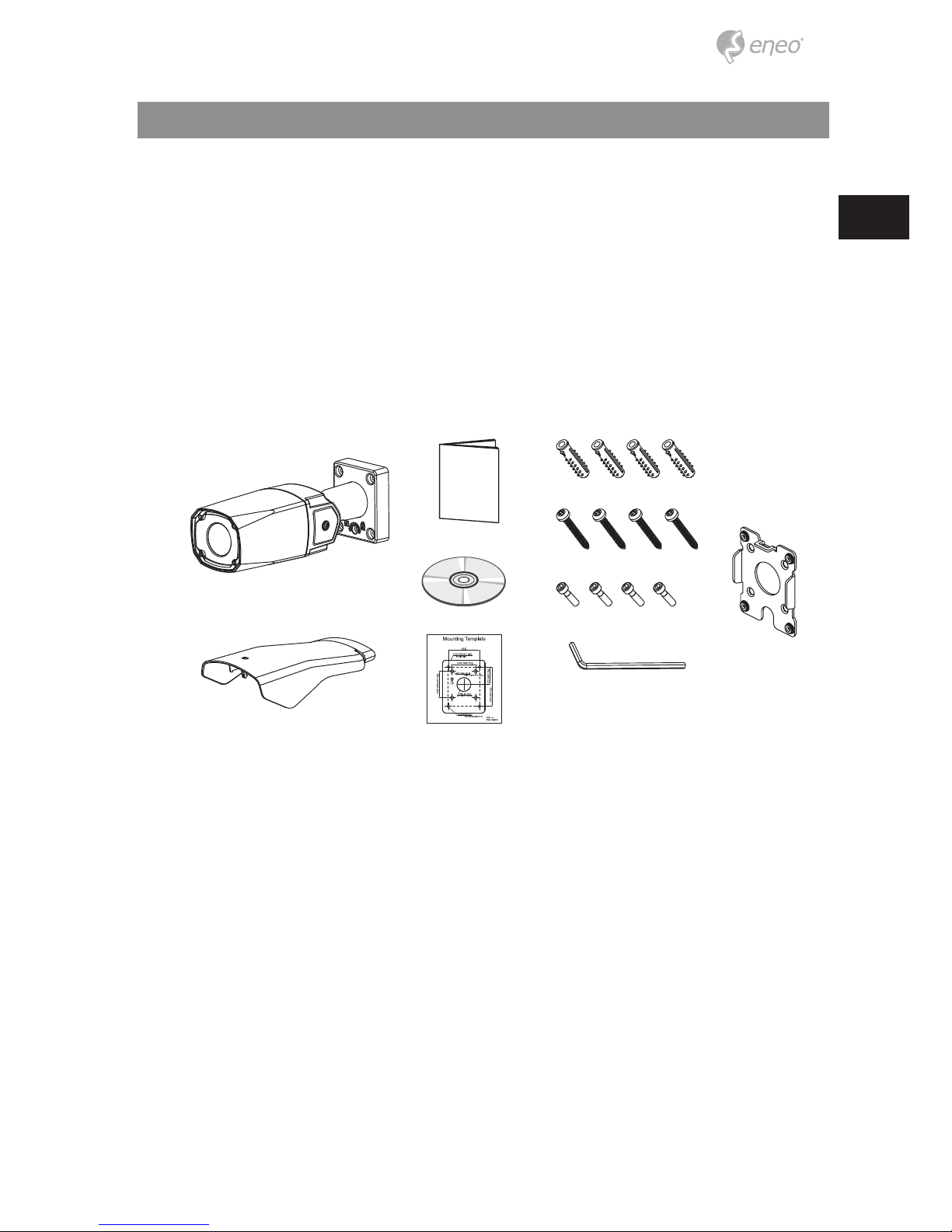
Parts supplied
• Network Camera
• Operating Instruction
• CD
• Mounting Template
• Sunshield
• Plastic Anchor: 6 x 30mm (4x)
• Mounting Screw: 4 x 35mm (4x)
• Assembly Screw: 4 x 13mm (4x)
• Torque Wrench: 3mm (1x)
• Easy Bracket
6
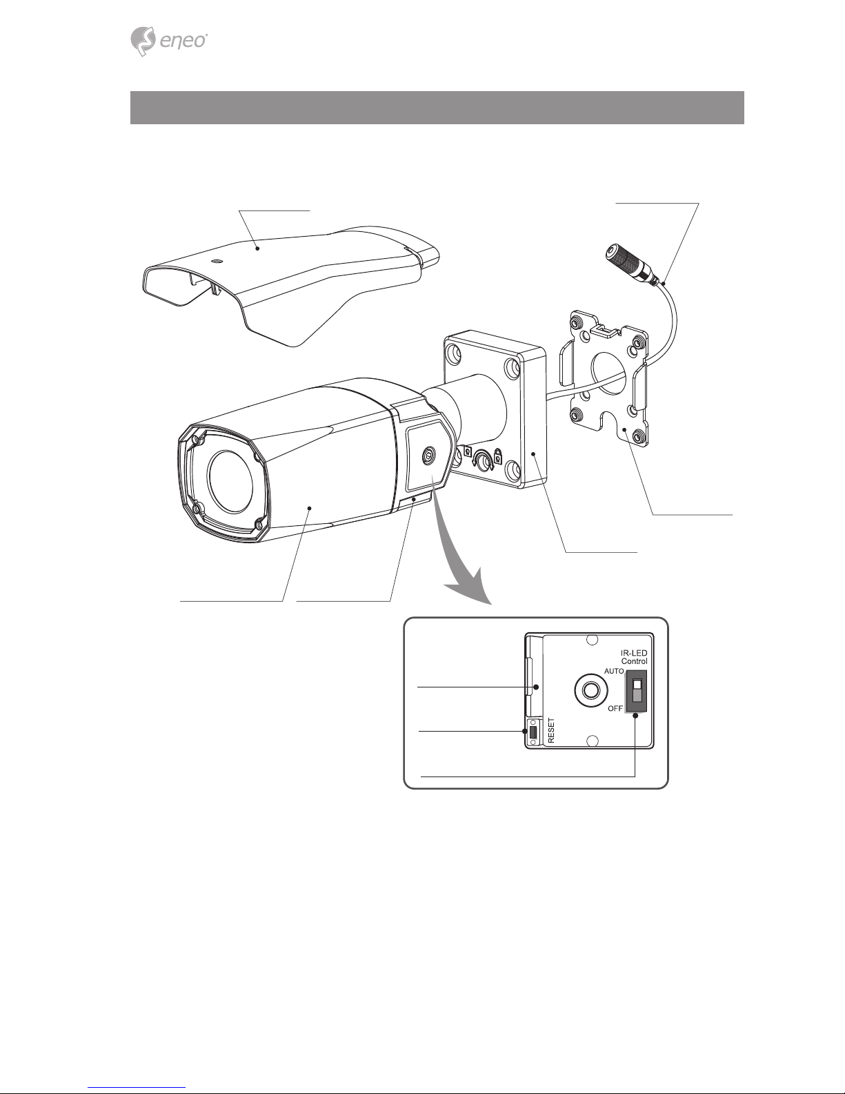
Part names
Micro SD Card Slot
Reset Button
LED Control Switch
SUNSHIELD
FRONT CASE
EASY BRACKET
BRACKET
REAR CASE
RJ-45 Connector
7
EN
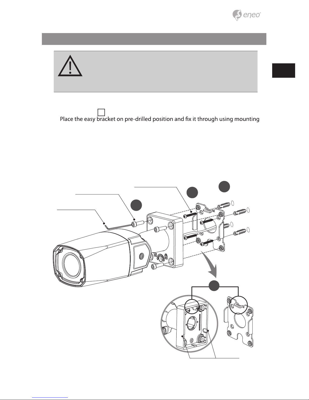
Installation instructions
CAUTION: The camera’s base should be attached to a structural
object, such as concrete, hard wood, wall stud or ceiling rafter
that supports the weight of the camera. If necessary use appropriate mounting material (e.g. anchors) instead of the material
enclosed with the camera.
1. Locate the mounting template at the installation position and drill the ceiling or
wall if needed.
i
The easy bracket can not be installed on the ceiling.
2.
screws(4x35mm). Skip this step when an easy bracket is not installed.
3. Route the ethernet and power cable to the connecting place. Hook up the camera
bracket with the easy bracket as illustrated below.
4. Fix the camera bracket through using assembly screws (4x13mm).
5. Set the camera’s viewing angle.
6. Put the sunshield to the camera unit.
Torque Wrench
Assembly Screw: 4x13mm
Mounting Screw : 4x35mm
1
2
4
3
Cable exit
8
CAUTION:
Extreme care should be taken NOT to scratch the window in front
of lens.
Care should be taken the cable is NOT to be damaged, kinked or
exposed in the hazardous area.
Do not expose the camera directly to a strong light source such
as the sun or spot light.
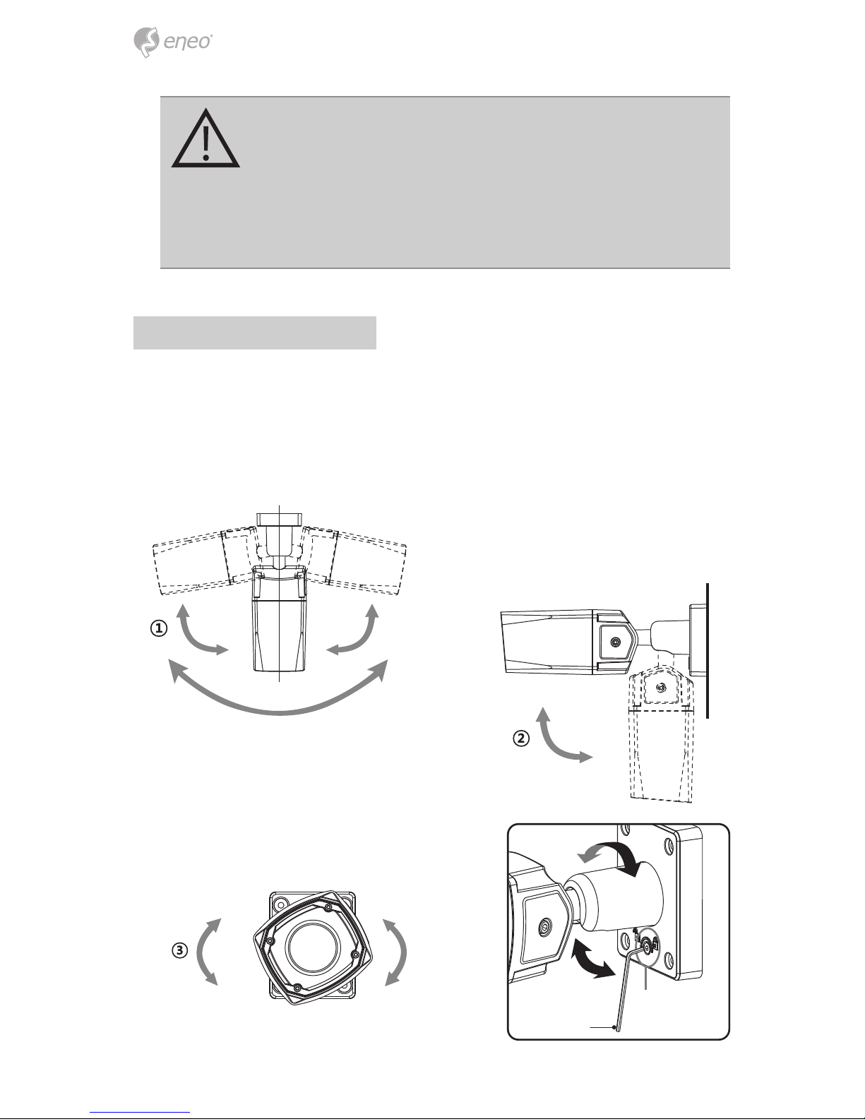
Pan & Tilt adjustments
• Unlock the screw on the camera bracket through using the torque wrench supplied
• Set the camera’s viewing angle then lock the screw on the bracket.
Adjustment of viewing angle with a bracket
1. Pan limit: Pan is limited to +/- 80°.
2.
80° 80°
160°
90°
2. Tilt limit: Tilt is limited to 0° min ~ 90° max.
for wall(ceiling) installation respectively
with reference to the wall(ceiling) when
the inclination of camera module is 0°,
that is, the image is aligned horizontally.
±90°
3. Inclination limit (Horizontal image alignment):
Inclination limited to +/-90° max.
Torque wrench
Lock / Unlock
screw
9
EN
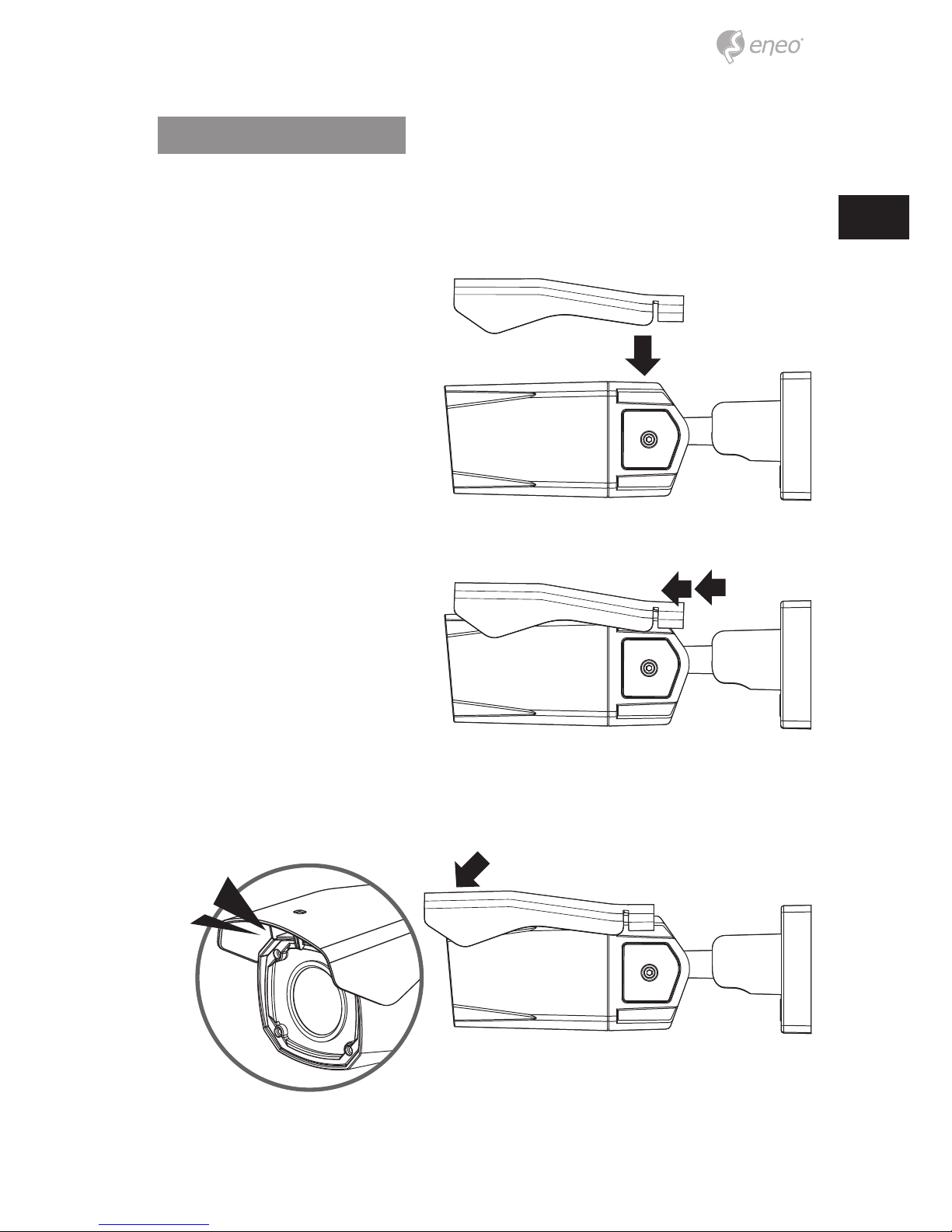
Sunshield assembling
After all adjustments, assemble the sunsheild with the camera unit as illustrated.
1. Cover the sunsheild to the camera unit.
2. Slide foward to straight the camera front case.
3. Push down the front part of sunshield until clicking sound.
Make sure the sunshield is xed with camera.
10
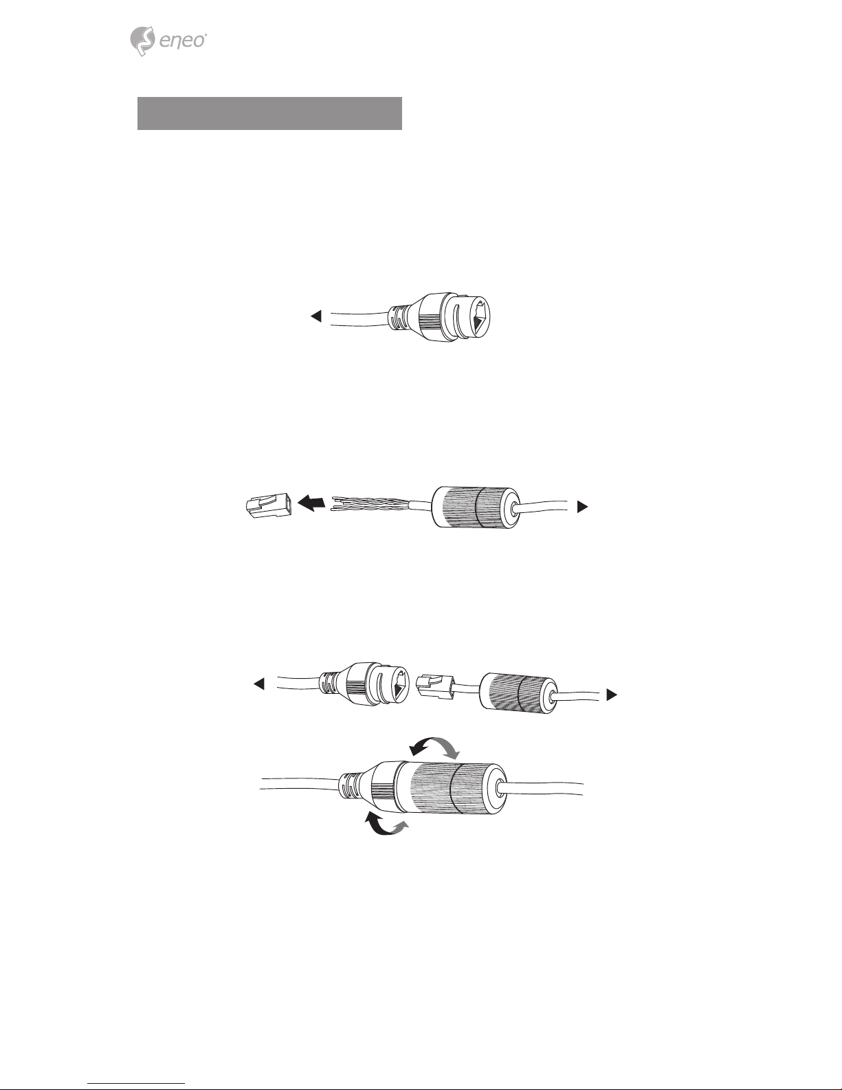
Power supply connections
Make sure the power is removed before the installation. Camera can work with PoE
(IEEE Std. 802.3af). After all connections are nished properly, plug the network cable
into RJ-45 Ethernet Port and PoE is the unique power.
1. RJ-45 female connector is on the LAN cable from Camera.
2. Extension cable should be passed through the connector without RJ-45
connector. After then, extension cable should be assembled with RJ-45
male connector.
3. RJ-45 male connector from extension side should be plugged in. Tighten
all plugs rmly to ensure waterproof.
Camera side
Camera side
Extension side
Extension side
11
EN
Quick Network Setup
1. After the camera is connected to the network, start ‘eneo Scan Device’ tool (enclosed CD).
2. Use the ‘Scan eneo’
3. By default the camera is set to DHCP. If there is no DHCP server present in the network the camera will fall back to a default IP address after a while. In this scenario
identical IP addresses.
The network camera‘s default IP address is: 192.168.1.10.
4. Right clicking the device name in the eneo Scan Device tool will bring up the
context menu. Use the ‘Open Device Web Site’ option to access the camera.
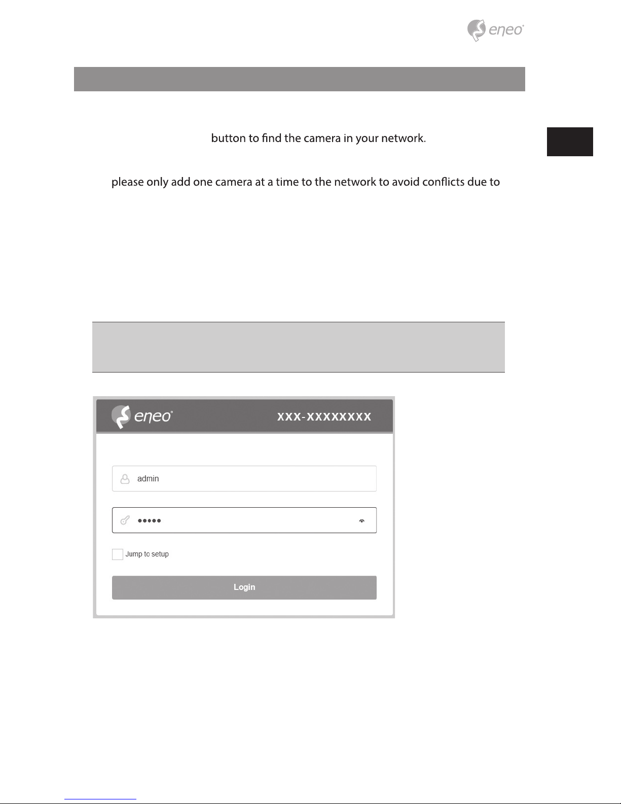
5. The web viewer login page will open up in your default web browser.
In case of Microsoft Internet Explorer install Active-X named VIDEOR E. Hartig
GmbH according to the instruction at the bottom of the browser.
6. Use the default user name and password to log in.
Default user name: admin
Default password: admin
12
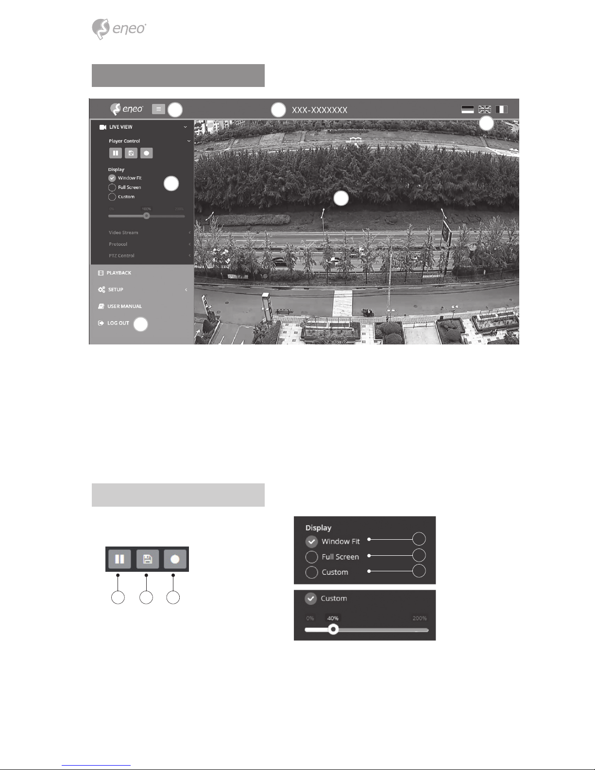
Web viewer description
(A) Menu button : Click the button to show or hide the setup menu bar.
(B) Model name : Show a camera model name connected.
(C) Select Language : Set the web viewer language English, Deutsch or French.
(D) Main setup menu bar : Set the camera or network functions.
(E) Camera monitoring window: Display the currently connected camera view or
function.
(F)
Log out and exit the web viewer
Player control & Display
(1) Pause: Freeze the current video.
(2) Snapshot: Take a picture of the video image currently on display. Supports the
origin image size view, print, and save feature.
(3)
Record: Record the current video on display.
A B
C
D
F
E
1 2 3
4
5
6
13
EN
(4)
(5)
(6)
Full Screen: Expand the current windows into maximum monitor size. Clicking
ESC button or right button on mouse to back to the normal view.
Custom: Move the control bar to make preferred window size.
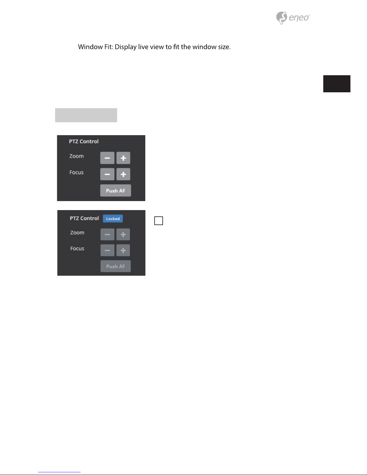
PTZ Control
Used to adjust zoom/focus manually or one-push
focus automatically.
• Zoom: Adjusts camera image zoom in/out ratio
manually.
• Focus: Adjusts camera image focus manually.
• Push AF: When Push AF command is sent, camera
becomes Auto Focus mode to adjust focus position
for a while.
i
Note:
• This option is activated Motorized lens / AF- Zoom
lens model only.
• Enable lens locking after completing zoom/focus
setting.
[ Setup> Video&Image> Image> AF]
• Do not adjust zoom/focus at low light condition,
night mode. It might cause erroneous focusing.
14
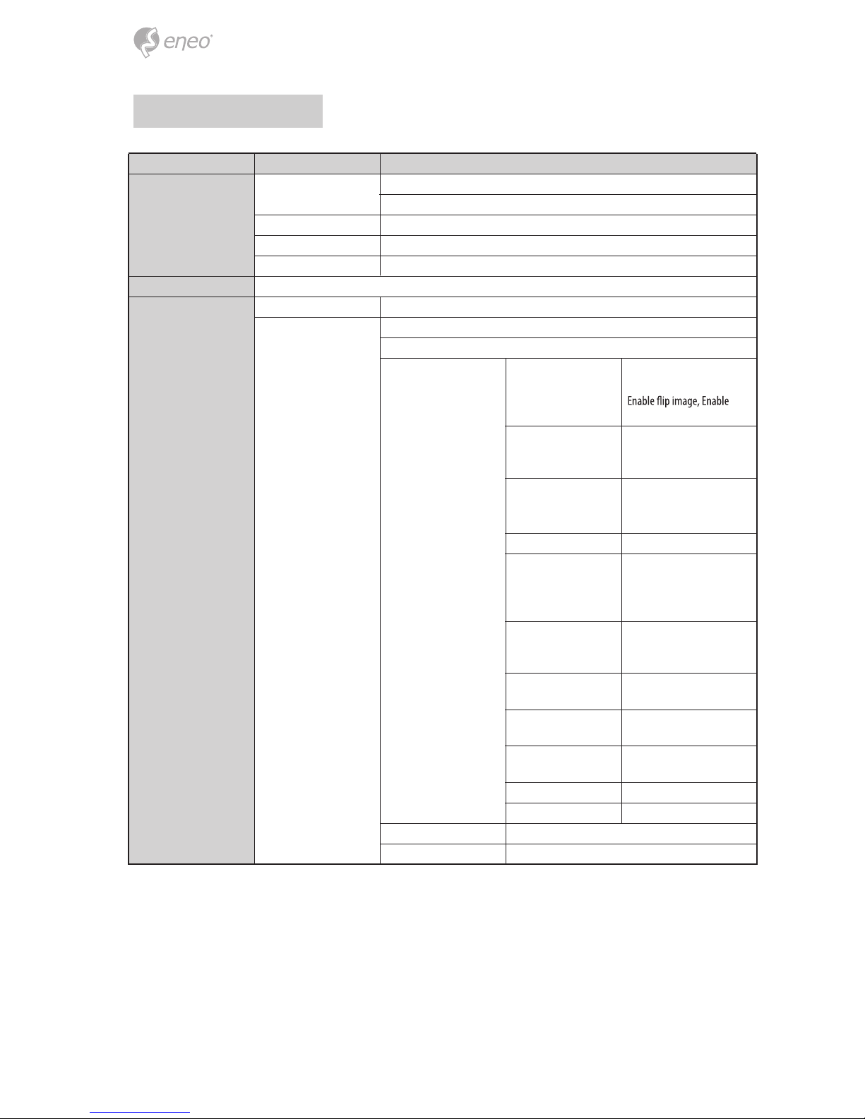
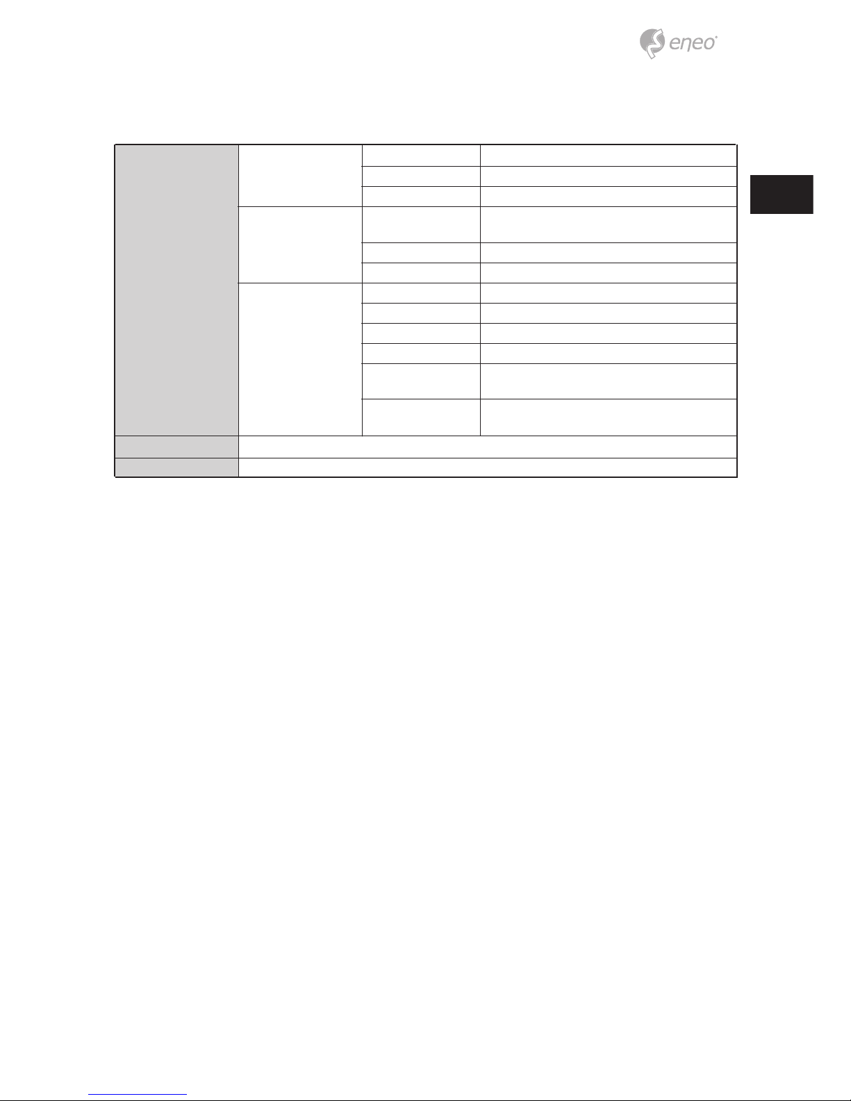
Setup Menu Table
Category Menu Conguration
LIVE VIEW
Player Control Pause, Snapshot, Record
Display (Window Fit, Full Screen, Custom)
Video Stream Stream1, Stream2, Stream3
Protocol HTTP, TCP, UDP
PTZ Contol Zoom, Focus, Push AF
PLAYBACK Event Search, Timeline Search, Timeline Bar
SETUP
Information General, System Information, Open source Information
Video & Image
Source
Image
Basic
Brightness, Contrast,
Saturation, Hue, Sharpness,
mirror image
OSD
Enable text OSD, Enable
date&time OSD, Enable
zoom&focus OSD, Mode
AE
AWB Mode, Cb Gain, Cr Gain
AF
Mode, Speed, Lens Locking,
Locking Timer, Lens Calibration, Enable Day&Night sync
focus
Day&Night
WDR
WDR(Mode, Level), Defog
(Mode)
BLC
BLC (Mode, Level), HLC
(Mode)
DNR
2DNR(Mode, Level),
3DNR(Mode, Level)
LDC Mode, Level, Boundary Line
VerticalView Mode, Rotation
Privacy Mask Color, Name
Digital Zoom Level
Mode, Switching time,
Threshold (D->N), Threshold
(N->D), Smart IR
Mode, Shutter, Max.shutter,
Gain, Max gain, Slow shutter,
Auto iris, Auto icker-less
Stream1/2/3, Snapshot
EN
15
SETUP
Record
Record
Overwrite when storage is full,
Continuous record setting
Schedule
Storage Format, Remove, Storage Information
Event
Triggers
Motion, VCA, Tamper, System, Manual, Network, Timer,
Day/Night
Actions Record, E-Mail, FTP, Video Boost, Notication Server
Rules Event Processing, ONVIF Mapping
System
Security User, HTTPS, IP Filter, ONVIF, Video Stream, Export/Import
Date & Time Current Time, New Time, Time Zone, Date & Time Display
Network TCP/IP, DDNS, RTP, UPnP, Zeroconf, Bonjour
Language English, German , French, Korean, Polish, Finnish
Maintenance
Maintain(Restart, Reset, Default), Upgrade, Setup Export,
Setup Import
LOG OUT
USER MANUAL
Logs & Report
Logs (Database Capacity, Search Condition, Log List),
Report
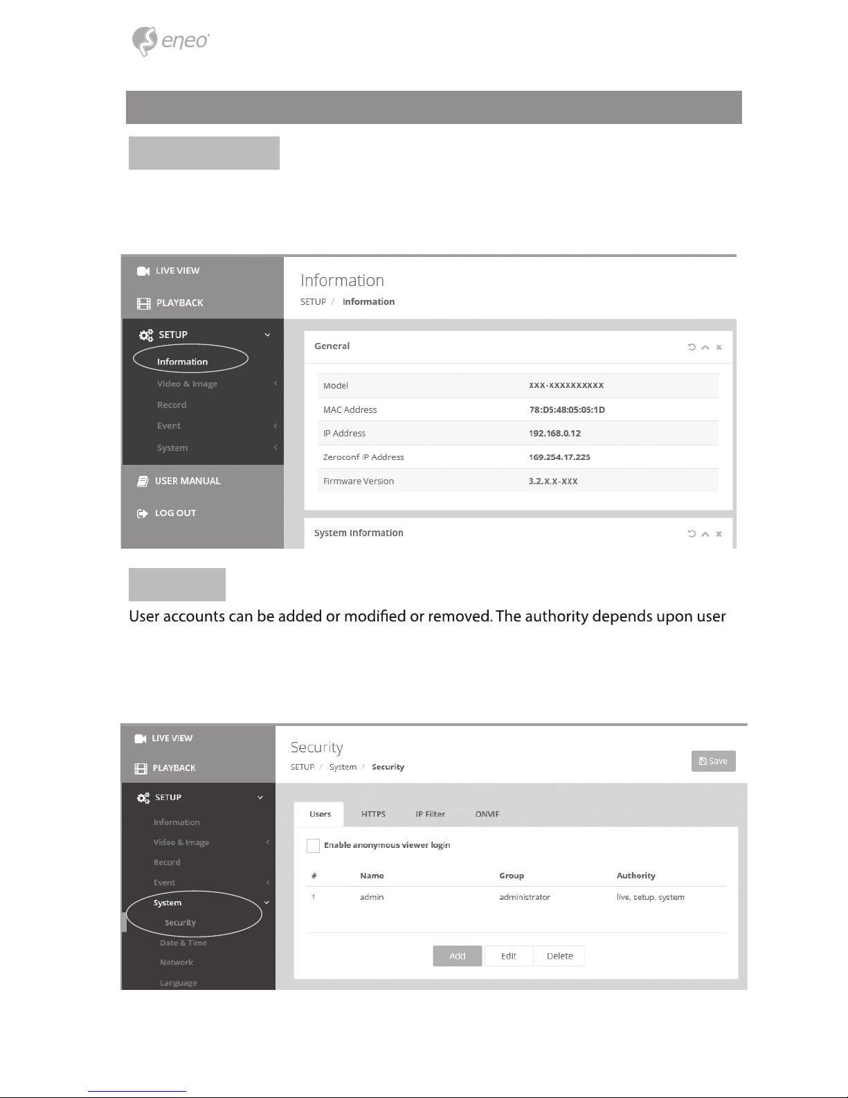
Click the Add, Edit, or Delete button for managing user account.
16
Quick Setup
Information
Users
group automatically and shows the permission status to access the menus.
• Name: Shows the name which registered to access the camera.
• Group: Shows the assigned permission given to users.
• Authority: Shows the permission status to access the menus.
The Information shows the camera information such as Model name, MAC address, IP
address, Zeroconf IP address, Firmware version, Server time, Running time, CPU Usage,
Incoming/Outcoming Bandwith and Open source list.
Video Stream Export/Import
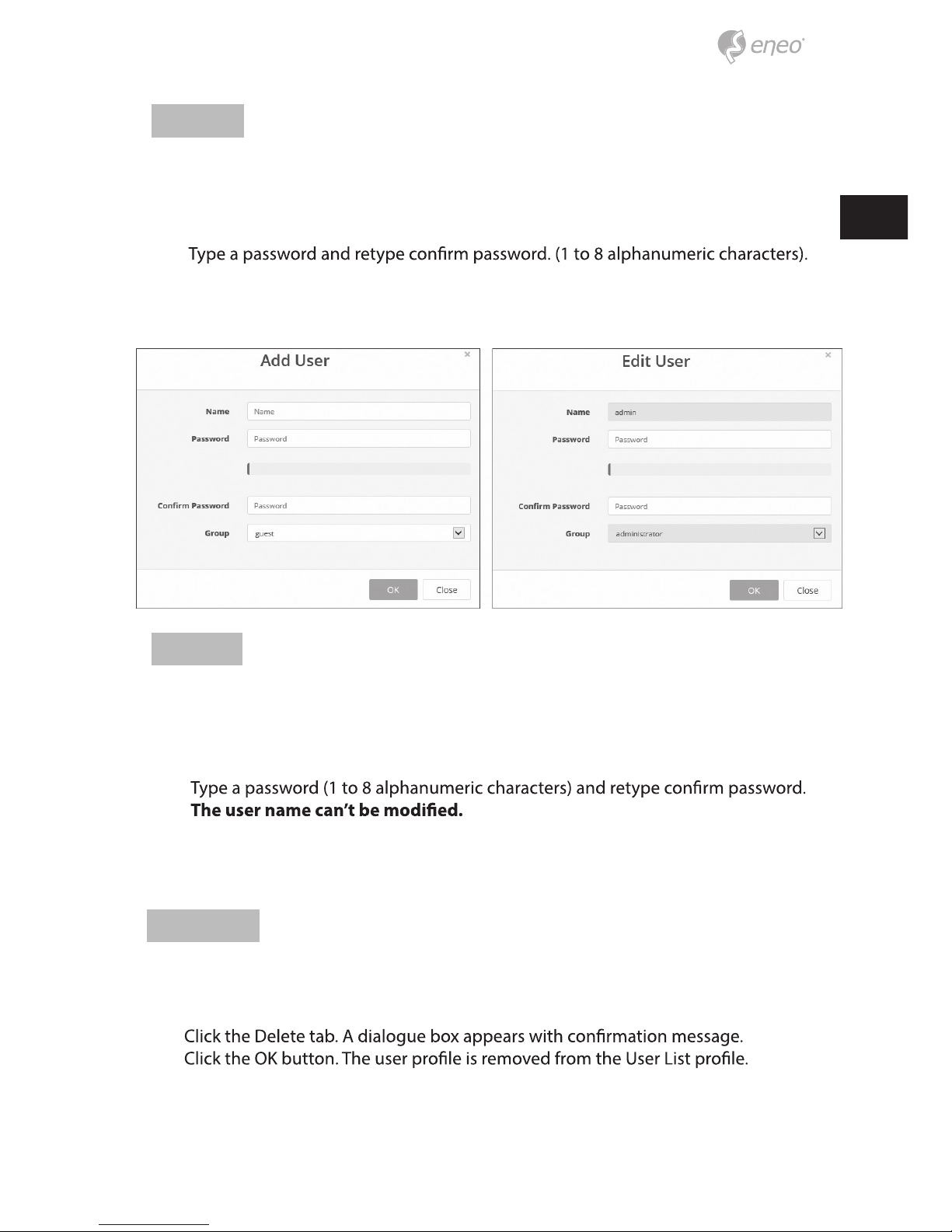
Add
To add a new user:
1. Click the Add tab, and type a new user name. (1 to 14 alphanumeric characters).
User names are not case sensitive.
2.
Passwords are case sensitive.
3. Select one of the groups you wish to assign to the user.
4. Click the OK button to save the settings and add a new user.
Edit
To edit a user:
1. Select one of the User Names in the User List you want to modify.
2. Click the Edit tab, then new pop-up window appears.
3.
4. Select one of the groups you wish to assign to the user.
5. Click the OK button to save the settings and modify a user.
Delete
To delete a user:
1. Select one of the User Names in the User List you want to remove.
2.
3.
17
EN
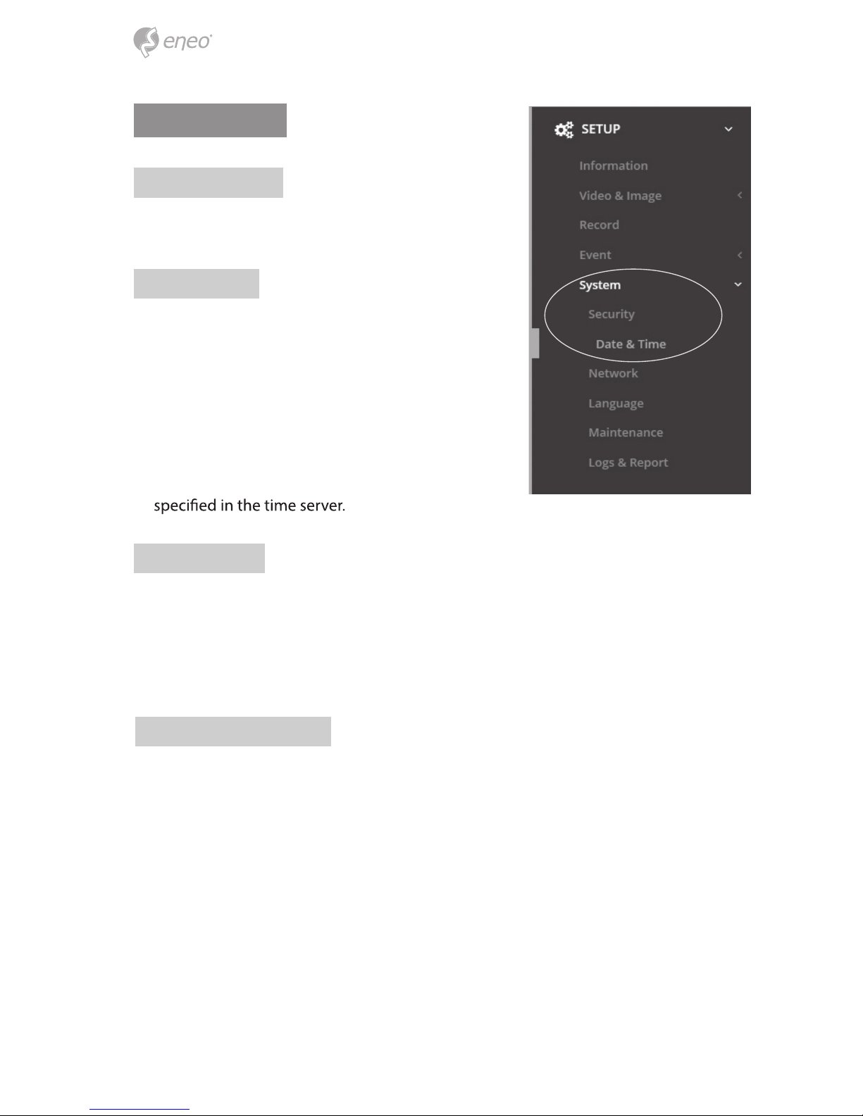
Date & Time
Current Time
Shows the current date and time.
New Time
Select one of the server time.
• Synchronize with computer time: Sets the time
according to the clock on your computer.
• Set manually: Using this option allows you to manually enter the date and time.
• Synchronize with NTP Server: This option will
obtain the correct time from an NTP server every 60
minutes. The NTP server’s IP address or host name is
Time Zone
Select the time zone where your camera is located. Click the “Automatically adjust for
daylight saving changes” checkbox to automatically update the time changes caused
by daylight saving.
Time zone: The default setting is GMT.
Day & Time Display
Select one of the Date and Time format.
• Date Format: The default setting is YYYY-MM-DD.
• Time Format: The default setting is 24 hours.
18
 Loading...