

Eneo GLS-2301H, GLS-2202H Installation And Operating Manual
1
Installation and Operating Manual
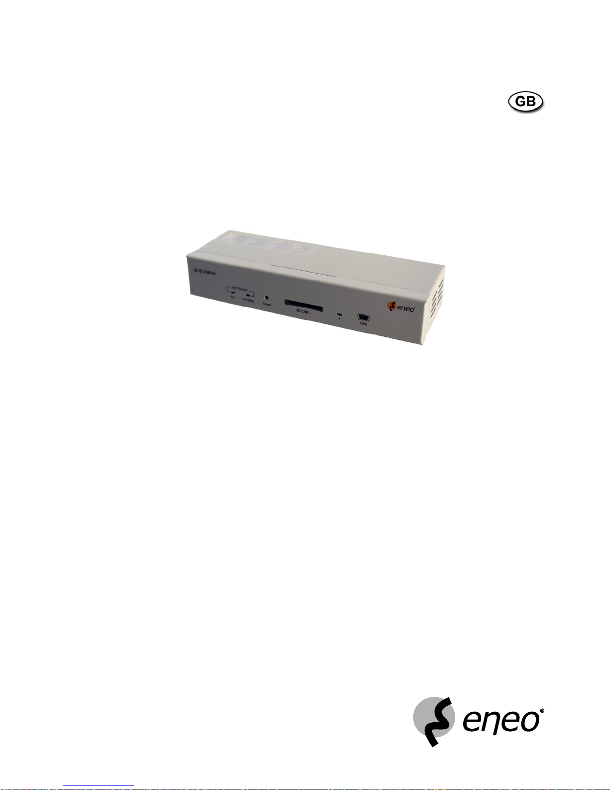
Network 1-Channel Video/Audio Server,
MJPEG, H.264, Ethernet
GLS-2301H

2
Contents
1. Safety Instructions / Maintenance .......................................................................................................................3
2. Product Features ................................................................................................................................................
4
2.1 Product Introduction .................................................................................................................................4
2.2 General Description ..................................................................................................................................4
3. Description of the Front/Rear View ......................................................................................................................
5
3.1 Front Panel ...............................................................................................................................................5
3.2 Rear Panel ................................................................................................................................................6
3.3 ALARM I/O PIN Configuration ....................................................................................................................7
3.4 The USB Function .....................................................................................................................................8
3.5 PoE (Power over Ethernet) ........................................................................................................................9
4. Installation........................................................................................................................................................10
4.1 Updating System Software .....................................................................................................................10
4.2 Video Server SD Card Troubleshooting ................................................................................................... 11
5. Network Configuration ......................................................................................................................................
12
5.1 Cable Connections ..................................................................................................................................12
5.1.1 Connect to a Computer ..........................................................................................................12
5.1.2 Connect to a LAN Switch (INTRANET) ....................................................................................13
5.1.3 Connect to a PoE Switch ........................................................................................................13
5.2 Configure your Video Server Network Settings ........................................................................................14
5.2.1 Enable DHCP Function .............................................................................................................14
5.2.2 Set IP Address ........................................................................................................................14
5.3 TCP/IP Communication Software ........................................................................................................15
5.4 TCP/IP Installation ................................................................................................................................16
5.5 TCP/IP Configuration Setting ...............................................................................................................17
5.6 Connection Testing ...............................................................................................................................18
6. Operating Instructions for Image Software and Network ...................................................................................
20
6.1 Microsoft Internet Explorer ......................................................................................................................21
6.1.1 Connecting the Video Server .....................................................................................................21
6.1.2 Change Image Setting ..............................................................................................................23
6.1.3 Change the Network Setting .....................................................................................................25
6.1.4 Change the System Setting.......................................................................................................34
6.1.5 Change the Application Setting .................................................................................................42
6.1.6 View the SD Card filrs ...............................................................................................................49
6.1.7 Control the Speed Dome ...........................................................................................................50
6.1.8 PPPoE & DDNS .........................................................................................................................51
7. Advanced Operation .........................................................................................................................................
52
8. Specifications ...................................................................................................................................................55
9. Function of Client PC ........................................................................................................................................
57
APPENDIX
1 – Register as a DDNS Member ..............................................................................................................58
APPENDIX
2 – PoE Installation Method ...................................................................................................................... 62
APPENDIX
3 – FAQ ....................................................................................................................................................65

3
1. Safety Instructions / Maintenance
• Read these safety instructions and the operation manual first before you install and commission the unit.
• Keep the manual in a safe place for later reference.
• The system may only be commissioned and maintained by personnel authorized to do this and it must only be
carried out in accordance with relevant standards and guidelines.
• Never cover the ventilation slots to avoid overheating.
• Never insert metal objects or any other items into the vents. This may permanently damage the unit.
• Protect your unit from contamination with water and humidity to prevent it from permanent damage.
Never switch the unit on when it gets wet.
Have it checked at an authorized service center in this case.
• Never operate the units outside of the specifications as this may prevent their functioning.
• Do not operate the unit beyond their specified temperature, humidity or power ratings. Operate the unit only at a
temperature range of 0°C to +50°C and at a humidity of max. 80%.
• The unit should be protected against excessive heat, dust, damp and vibration.
• Do not place any heavy objects on the unit.
• To disconnect the power cord of the unit, pull it out by the plug. Never pull the cord itself.
• Pay attention when laying the connection cable and observe that the cable is not subject to heavy loads, kinks, or
damage and no moisture can get in.
• Contact your local dealer in case of malfunction.
• The connection cable should only be changed by Videor E. Hartig GmbH.
• The warranty becomes void if repairs are undertaken by unauthorized persons. Do not open the housing.
• Installation, maintenance and repair have to be carried out only by authorized service centers.
Before opening the cover disconnect the unit from mains input.
• Only use original parts and original accessories from Videor E. Hartig GmbH.
• Do not use strong or abrasive detergents when cleaning the dome. Use a dry cloth to clean the dome surface.
In case the dirt is hard to remove, use a mild detergent and wipe gently.
NOTE: This is a class A digital device.
This digital device can cause harmful interference in a residential area; in this case the user may be
required to take appropriate corrective action at his/her own expense.
www.videor.com
⇒
Montage- und Betriebsanleitung
Installation and Operating Instructions
Mode d’emploi
Instrucciones de manejo

4
2. Product Features
2.1 Product Introduction
This video server is an ideal user-friendly device which brings digital benefits to your analog surveillance cameras.
The tiny and compact body design can be easily installed in all kinds of analog cameras for network surveillance.
The video server adapts Texas Instrument’s (TI’s) newest digital media processor - the Da Vinci DM 355 for efficient
image operation, while also offering simultaneous dual-codec (H.264 / MJPEG) video compressions with the highest
resolution, Full D1, at 30/25 frames per second in the NTSC/PAL systems, respectively. In addition, users based on
different bandwidths can choose multi-profile MJPEG video streaming at different resolutions.
The video server provides stable, reliable and convenient network surveillance. It safely downloads automatic video
Codec and other components, and lets you set up the control settings very easily. It provides UPnP features as well.
Its USB interface is for basic network setting and updating. The SD card slot supports alarm and event recording
and updating. Furthermore, this encoder board comes with the Power over Ethernet (PoE) function, and its RS-485
interface can be connected with all kinds of Pelco-D PTZ cameras.
We have launched this dual-codec video server for the more advanced digital surveillance solutions demanded by
our clients. We believe this unit is the right answer to your Network surveillance problems. You will find it practical,
precise and indispensable.
2.2 General Description
• 1-channel Video/Audio Server for LAN/WAN/Internet
• Simultaneous Video Streaming (H.264 & MJPEG)
• Image Frame Rate: up to 25 ips. (720x576 Px.)
• RS-485 Telemetry Control Interface
• Alarm Input/Outputs
• Motion Detection
• Integrated Web Server: 10Base-T/100Base-TX
• Viewer for Monitoring, Recording and Configuration
• Pre and Post Event Recording (in Client PC)
• SD Socket for Local Video Storage by SD Cards
• E-Mail Notification in Case of an Alarm
• Basic Setting via USB Interface and Network
• Power Input via Power over Ethernet and 12VDC/24VAC
FACTORY DEFAULT • IP Address: 192.168.1.168
• Password: 9999
5
3. Description of the Front/Rear View
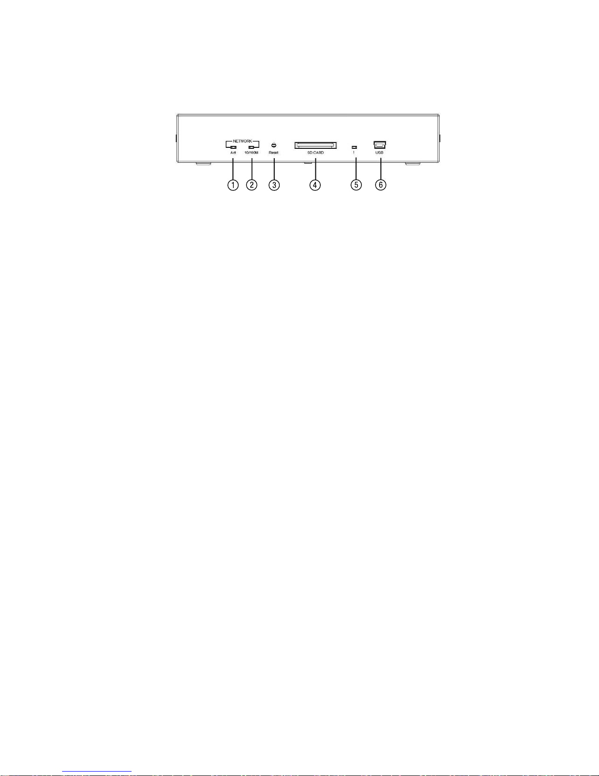
3.1 Front Panel
1. Act indicator
Indicates the network status of the unit. The green light indicates the network is activating.
2. 10/100M indicator
The green light indicates the network data are transmitting.
3. Reset button
Recover to factory default.
4. SD CARD Slot
This is used for system software updating and archiving / accessing critical images
5. Status indicator
If this LED light is on, it means the SD card is recording or the device is updating.
6. 5pin MINI B Port
The user can use a USB device cable to connect the Video Server to the USB port on the PC.
6
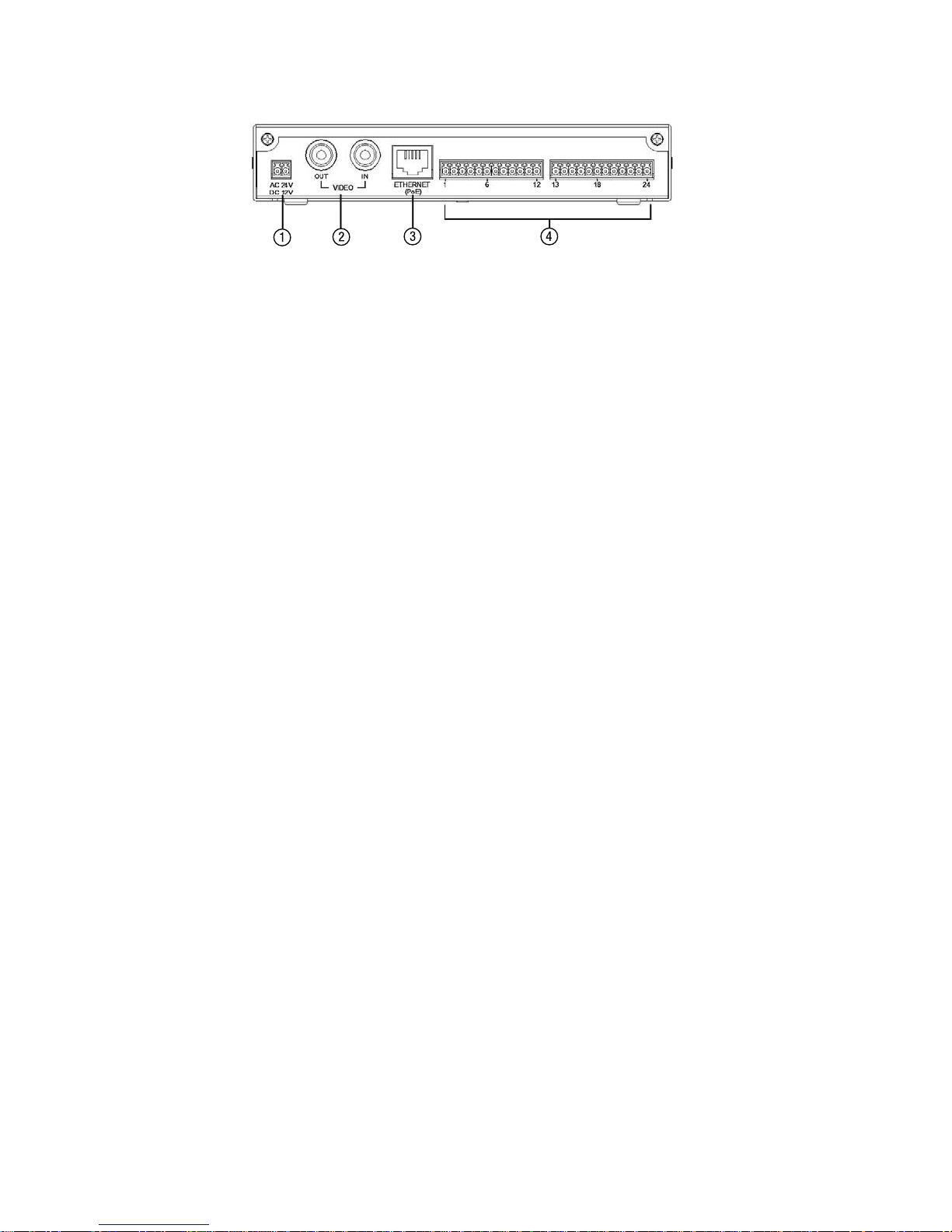
3.2 Rear Panel
1. DC jack
The inlet connects to an external power supply. Connect with the 12 VDC/24VAC TUV-approved Power Supply;
or connect with the UL Listed Class 2 Power Supply or ITE power supply marked ’LPS’ or its equivalent.
2. Video in connector
The BNC connector is used to connect to the video output from the camera. 1 camera can be connected to the
connector.
Video out connector
This BNC connector provides a video signal to the main monitor.
3. ETHERNET (PoE) Connector
This is a standard RJ-45 connector for 10/100 Mbps Ethernet networks. PoE (Power over Ethernet) function:
Provides power to the device via the same cable as used for the network connection.
NOTE: Please refer to the APPENDIX – PoE Installation Method for more details.
4. ALARM I/O
This is an 24-PIN connector including the alarm input x 6, alarm-out x6, GND x 6, RS-485+-(2 pins), audio input
and audio output items for connecting with external devices.

7
3.3 ALARM I/O PIN Configuration
1. RS-485 pin: D+
2. RS-485 pin: D–
3. GND1: Ground Contact
4. ALARM RESET (INPUT): This pin connects to an alarm-clear device for clearing an alarm (
5V
0V(Active)
).
5. GND2: Ground Contact
6. ALARM IN 1 (INPUT): This is an alarm input which can be programmed in the menu system to Normally Open
or Normally Closed (
5V
0V(Active)
).
7. ALARM IN 2 (INPUT): This is an alarm input which can be programmed in the menu system to Normally Open
or Normally Closed (
5V
0V(Active)
).
8. ALARM IN 3 (INPUT): This is an alarm input which can be programmed in the menu system to Normally Open
or Normally Closed (
5V
0V(Active)
).
9. ALARM IN 4 (INPUT): This is an alarm input which can be programmed in the menu system to Normally Open
or Normally Closed (
5V
0V(Active)
).
10. ALARM IN 5 (INPUT): This is an alarm input which can be programmed in the menu system to Normally Open
or Normally Closed (
5V
0V(Active)
).
11. ALARM IN 6 (INPUT): This is an alarm input which can be programmed in the menu system to Normally Open
or Normally Closed (
5V
0V(Active)
).
12. GND3: Ground Contact
13. AUDIO IN Connector: The connector is used to connect the audio output from a camera or other devices.
14. AUDIO OUT Connector: The connector provides the unit’s audio signal to a speaker or stereo.
15. GND4: Ground Contact
16. ALARM OUT 1 (OUTPUT): This is an alarm-output trigger. Connect this to external devices such as buzzers or
lights (
5V
0V(Active)
).
17. ALARM OUT 2 (OUTPUT): This is an alarm-output trigger. Connect this to external devices such as buzzers or
lights (
5V
0V(Active)
).
18. ALARM OUT 3 (OUTPUT): This is an alarm-output trigger. Connect this to external devices such as buzzers or
lights (
5V
0V(Active)
).
19. ALARM OUT 4 (OUTPUT): This is an alarm-output trigger. Connect this to external devices such as buzzers or
lights (
5V
0V(Active)
).
20. ALARM OUT 5 (OUTPUT): This is an alarm-output trigger. Connect this to external devices such as buzzers or
lights (
5V
0V(Active)
).
21. ALARM OUT 6 (OUTPUT): This is an alarm-output trigger. Connect this to external devices such as buzzers or
lights (
5V
0V(Active)
).
22. GND5: Ground Contact
23. DC-OUT: DC-12V 350mA max.
24. GND6: Ground Contact
8
3.4 The USB Function
By connecting the video server board with a PC via the USB connector, the video server board can provide different
functions.
1. Insert an SD card: As a card reader
Insert an SD card into the Video Server, then connect to the PC. You might transfer files between the SD card
and the PC. Once you’ve connected your Video Server to your computer, the Windows system will detect the
connection and ask you what you want to do with your SD card.
In another words, if the user connects the Video Server with an SD card and the PC via the USB connector, the
Video Server can be used as a normal card reader.
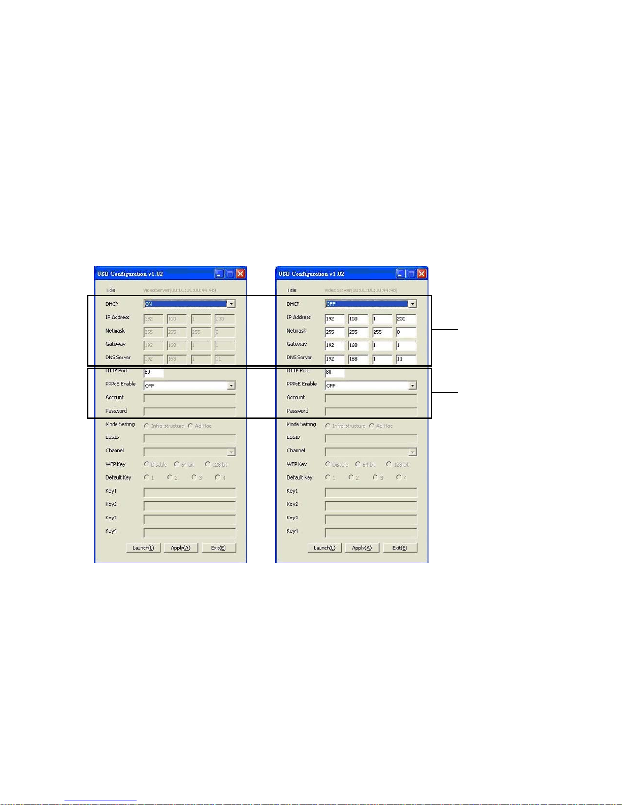
2. As a configuring tool:
By connecting the Video Server with a PC via the USB connector, you can set the Network and PPPoE functions
of the Video Server directly by your PC.
Network
Setting
PPPoE
Setting
DHCP ON
DHCP OFF
NOTE: You can click the ”Launch” button to link to the home page of the Video Server.
WARNING: After changing the settings, please click the „Apply” button. All of the options will be effective
after removing the USB connector.

9
3.5 PoE (Power over Ethernet)
These technologies will enable the development of new networked appliances, by providing power as well as data
over existing Ethernet cables.
The Summary Comparison of PoE Standards (Table 1) is listed as follows.
Connect to a PoE Switch
The Standard RJ-45 PIN configuration for connecting with a PoE Switch is shown below.
Table 1. Summary Comparison of PoE Standards
STANDARD
SOURCE
LOAD
REMARKS
Source
Voltage
Ethernet RJ-45 connector pin number *
1 2 3 4 5 6 7 8
Load
Voltage
DC Load
Connec-
tor
IEEE
802.3af
using data
pairs
48VDC,
protected
RX,
DC+
RX,
DC+
TX,
DC-
spare spare
TX,
DC-
spare spare (embedded)
Industry Standard
for embedded PoE
IEEE
802.3af
using spare
pairs
48VDC,
protected
RX RX TX DC+ DC+ TX DC- DC- (embedded)
Industry Standard
for embedded PoE
The compatible PoE Hubs (Table 2), which can be used with the unit, are shown in the tables below.
Table 2. Compatible PoE Switch
Manufacturer Model Port Note
PLANET
FSP-804P 4 Port PoE Switch
POE-151 1 Port PoE Switch
D-Link DWL-P200 1 Port PoE Switch
Video Server
PoE Switch
RJ-45
RJ-45
RJ-45
to Network
to PC
PoE
Power Inlet (Using the supplied
48V power supply,connect to a
wall power outlet.)

10
4. Installation
Please follow the instructions below to set up the system.
4.1 Updating System Software
If the system software of the Video Server needs to be upgraded, please take the following steps to safely process it.
IMPORTANT: Before carrying out the following procedures, please ensure the SD card is working and the file
of the system firmware is intact
1. Format an SD card using the FAT format if it is unformatted.
2. Create a directory named „VSERVER” in the SD card if it does not exist.
3. Copy the file of UPDATE.BIN to the VSERVER-directory.
4. If the Video Server is running, please power it off first.
5. Insert the SD CARD into the Video Server.
6. Remove the Ethernet cable from the RJ-45 port and then power on the Video Server.
7. In 5 to 10 seconds, a message reading „UPDATE PROCESSING” will show up on the screen on a blue back ground; if not, please check out steps 1 to 6 carefully or else inform your technical support while ignoring the
following steps.
8. DO NOT power off the Video Server while this update process is running until the message „UPDATE OK RESET
PLEASE” appears on the screen; it might take 15 to 30 seconds to appear.
9. If the message „UPDATE NG RESET PLEASE” appears rather than „UPDATE OK RESET PLEASE”, please write down
the error messages shown on the screen and inform your technical support, while ignoring the following steps.
10. Power off the Video Server when this update process is finished, then remove the SD card from the Video Server.
11. Reconnect the Ethernet cable to the RJ-45 port if necessary.
12. Power ON the Video Server and it will work normally if the entire update procedure goes correctly.
13. Verify the version of the system software.
WARNING:
1. Don’t use the NTFS format in step 1.
2. Steps 1 to 3 have to be done on a PC.
3. Make sure the file of UPDATE.BIN is a correct one in step 3, or the VIDEO SERVER will not work normally
after being updated.
4. If the power of the VIDEO SERVER is suddenly lost in step 8, please remove the SD card first and turn on
the VIDEO SERVER next to test its operation. If the VIDEO SERVER remains working normally, please go
back to step 4; otherwise, please inform your technical support.
5. In step 10, if the SD card is not removed and the Video Server does not get online as well, the updating
process must be repeated again after rebooting the Video Server.
6. Make sure that the SD card is inserted in a correct position in step 5, or the Video Server will suffer
permanent physical damage.
7. If the message „CSUM ERROR” appears in step 8, it implies a problem in the file of UPDATE.BIN.
8. Don’t interrupt the process while the unit is updating itself; proceed with an SD card not including any
system software of the unit, or else the unit will crash.

11
4.2 Video Server SD Card Troubleshooting
1. Check if the SD card position is correct or not. Please refer to the manual for the related information.
2. After powering the Video Server on, correctly insert the SD card, and a little icon of „SD” will show up in the
upper-right corner of the monitor screen. If not, it means the device detection has failed.
Please contact your technical support and ignore the following steps.
3. If no cross sign appears beside the „SD” icon, please go on to the next step. If a cross sign appears, please
check the following:
a. Is it really an SD „Memory” Card ?
b. Is this SD card formatted in the FAT16 format ?
c. Connect the SD card with a PC and test to see whether the PC can read the data or not.
d. Does this SD card still have the capacity for storing data ?
e. Is the SD card set to write ?
If all the answers are „yes” but the cross sign still persists, please contact your technical support and ignore the
following steps.
4. Please make sure the function of „SD CARD ENABLE” is activated in the ALARM and SCHEDULE pages if no
cross sign appears beside the „SD” icon on the screen.
5. After recording, read the data on the web page of „sdget.htm”. If the data cannot be read through the network,
please read it instead in a PC, check the data stored in the „VSERVER” directory and contact your technical
support regardless of whether there is data or not.
WARNING:
1. Performing this troubleshooting process may need a monitor, a PC, a card reader and some cables.
2. If the SD card is removed while storing or accessing data, the data will be lost.
3. If there is a cross sign beside the „SD” icon, it means the SD card has been inserted into the Video
Server but cannot perform its writing function. Possible reasons are:
a. It is not an SD memory card.
b. The SD card is unformatted or formatted in a non-FAT16 or non-FAT12 format.
c. The file system is damaged.
d. The capacity of the SD card is full.
e. The SD card is set to be read only.
4. Turn off the power before inserting the SD card. Otherwise the unit may shut down.
12
5. Network Configuration
5.1 Cable Connections
Please follow the instructions below to connect your Video Server to a computer or a network and to choose a proper
RJ-45 cable configuration for connections.
Physical specification of RJ-45 cable for Ethernet
Wire Type
Cat. 5 or above
Connector Type
RJ-45
Max. Cable Length
100m
Hub Wiring Configuration
Straight through or Cross Over
PC Wiring Configuration
Straight through or Cross Over
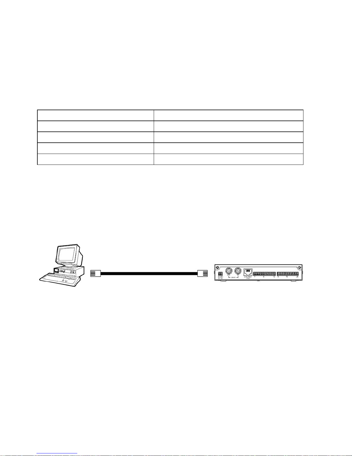
5.1.1 Connect to a Computer
Use a cable to connect directly to a computer.
RJ-45
Normal or crossover cable
to PC LAN card
NOTE: When connecting the PC and the Video Server Board, the PC and the Video must be assigned IPs,
which must be in the same class type as your network address.
13
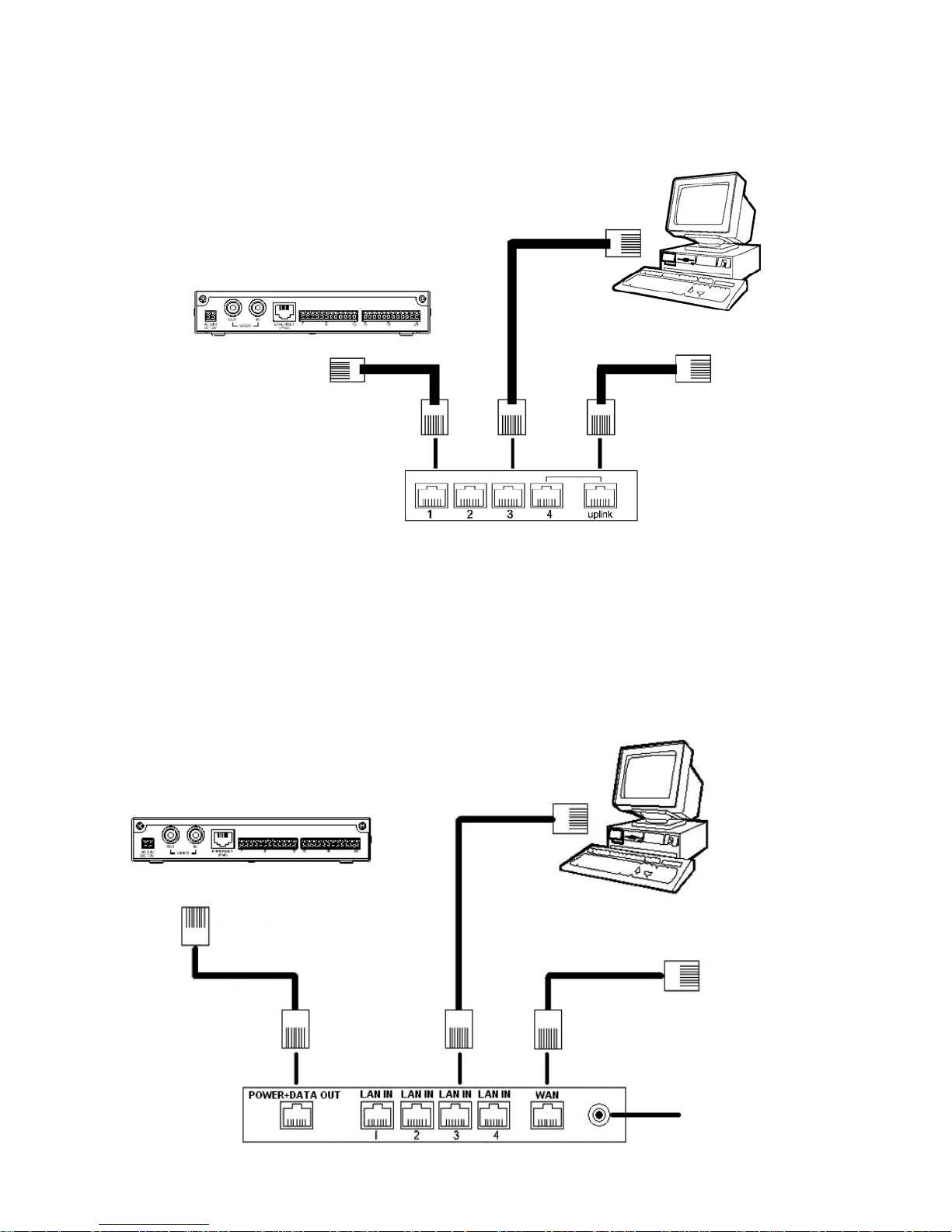
5.1.2 Connect to a LAN Switch (INTRANET)
The RJ-45 PIN configuration for connecting with a LAN Hub.
Switch
RJ-45
to Network
to PC
Network card
Video Server
PoE Switch
RJ-45
RJ-45
RJ-45
to Network
to PC
PoE
Power Inlet (Using the
supplied 48V power
supply, connect to a wall
power outlet.)
5.1.3 Connect to a PoE Switch
The Standard RJ-45 PIN configuration for connecting with a PoE Switch is shown below.
14
5.2 Configure your Video Server Network Settings
Upon connecting with the network hardware, you need to activate the network function and configure the proper
network settings of the Video Server.
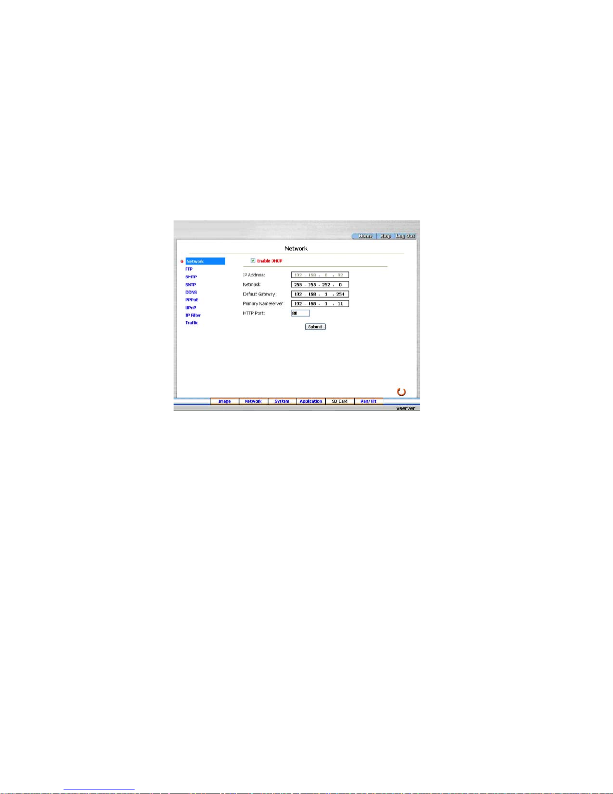
5.2.1 Enable DHCP Function
The user can use the USB function (refer to section 3.4) or the Internet Explorer (refer to section 6.1.3) to enable the
DHCP function.
This function can only work if the LAN, which the unit is connected to, has a DHCP server. If the DHCP server is
working, the Video Server will obtain an IP address automatically from the DHCP server. In that case, please skip
section 5.2.2 (Set IP address) and follow section 5.3 (TCP/IP Communication Software).
5.2.2 Set IP Address
You need to set an IP address for the unit if the LAN unit isn’t connected to a DHCP server.
Otherwise, please follow the instructions given below:
Set the
IP, MASK and GATEWAY. The following is a sample setting.
IP: 192.168.1.X
MASK: 255.255.255.0
GATEWAY: 0.0.0.0
NOTE: When only one unit of the Video Server is connected to a computer or LAN, you can freely assign
an IP address for the Video Server. For example, there is a range of Video Server IP addresses from
192.168.1.1 to 192.168.1.255. You can pick one for use from the range of the IP. It’s not necessary
to set MASK and GATEWAY; leave the settings as default.
15
When a Video Server is connected to a WAN, you must acquire a unique, permanent IP address and
correctly configure the MASK and GATEWAY settings according to your network architecture. If you
have any questions regarding those settings, please contact a qualified MIS professional or your ISP.
NOTE: When connecting to a network, each connected Video Server must be assigned a unique IP, which
must be in the same class type as your network address. IP addresses are written as four sets of
numbers separated by periods; for example, 192.168.1.1 Therefore, if the connected network is
identified as Class C, for example, the first three sets of numbers of the Video Server IP address must
be the same as the network address. If the connected network is identified as Class B, the first two
sets of numbers of the Video Server IP address must be the same as the network address. If you have
any questions regarding these settings, please contact a qualified MIS professional or your ISP.
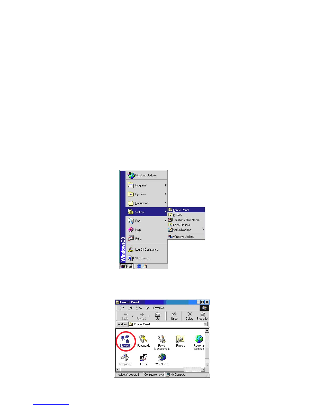
5.3 TCP/IP Communication Software
Follow the instructions below to install the TCP/IP communication program into your computer.
Click the
Start menu from your computer, and point to the Settings/Control panel.
Double click the Network icon to enter the windows.
16
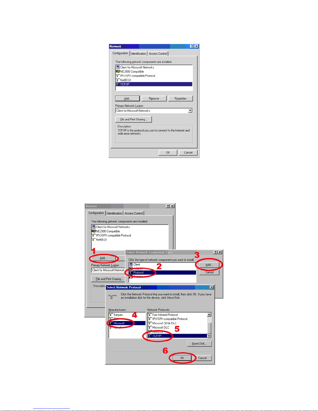
Click the Configuration tag, and check if the TCP/IP is included among the network components list. If the TCP/IP is
included, please process section 5.5. If it is not included, please follow section 5.4 to install the TCP/IP.
During the installation, you will be requested to insert the Windows CD-ROM. After installation, the PC may be restarted.
5.4 TCP/IP Installation
17
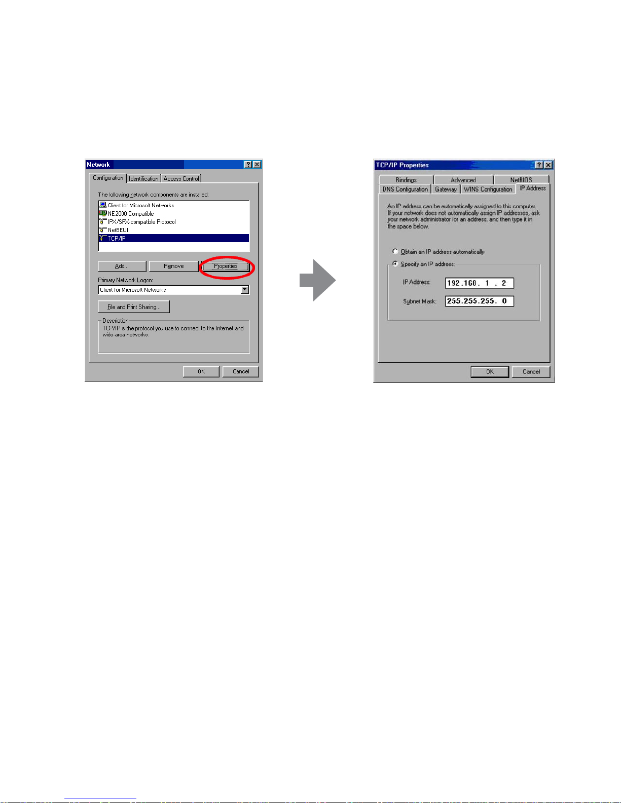
5.5 TCP/IP Configuration Setting
Click Start –> Settings –> Control Panel –> Network
Select
TCP/IP, and then click Properties.
Before processing the Video Server installation in a WAN, please make sure the Internet connection works properly.
If not, please contact your ISP provider.
If you are using a DHCP server, please select Obtain an IP address automatically. Any assigned IP address for
the connected Video Servers must be in the same class type as the server. If there is no DHCP server, please select
specify an IP address and type in the IP address of your PC. This IP address must be different from other network IP
devices but in the same class type.
NOTE: The IP address of a Video Server in a network must be unique to itself as opposed to those of the
other chosen PCs, but in the same class type.
18
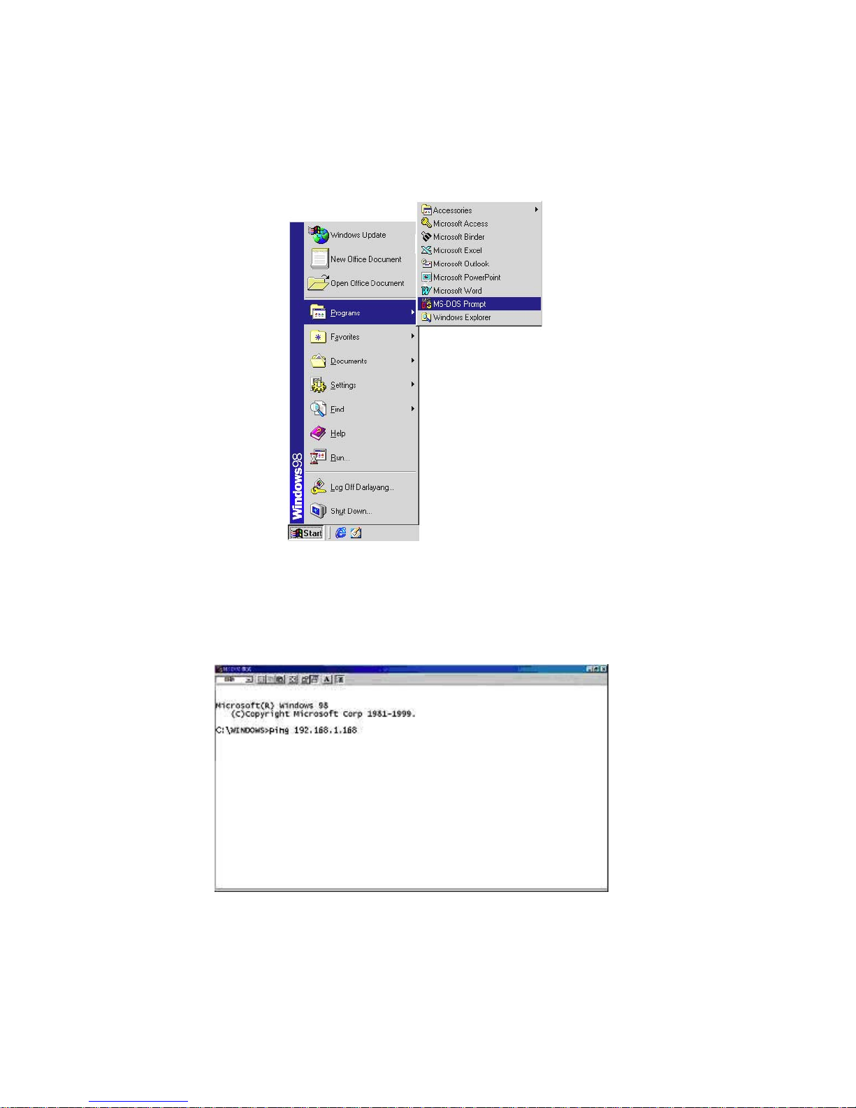
5.6 Connection Testing
With the previous settings, follow the instructions below to ensure whether you have established the connection
successfully.
Click
Start –> Programs –> MS-DOS Prompt
Type in
ping 192.168.1.168 then Enter. (See the sample screen below)
• This IP is the Video Server IP address that is assigned for the connected Video Server in step 2.

19
If you receive a response as in the sample screen below, you have successfully made the connection.
If you receive a response as in the sample screen below, the connection hasn’t been successfully established.
Please re-check all the hardware and software installation by repeating steps 1 to 5. If you still can’t establish the
connection after re-checking, please contact your dealer.
20
6. Operating Instructions for Image Software and Network
Two choices of software are available for linking with the Video Server: (1) the Microsoft Internet Explorer; and (2) the
eneo GL-Manager, a network browser in a PC which provides the functions of monitoring remote zones or watching
recorded data through the TCP/IP protocol.
The details are listed as follows.
Wire Type
Cat. 5
Connector Type
RJ-45
Max. Cable Length
100m
Hub Wiring Configuration
Straight through or Cross Over
PC Wiring Configuration
Straight through or Cross Over
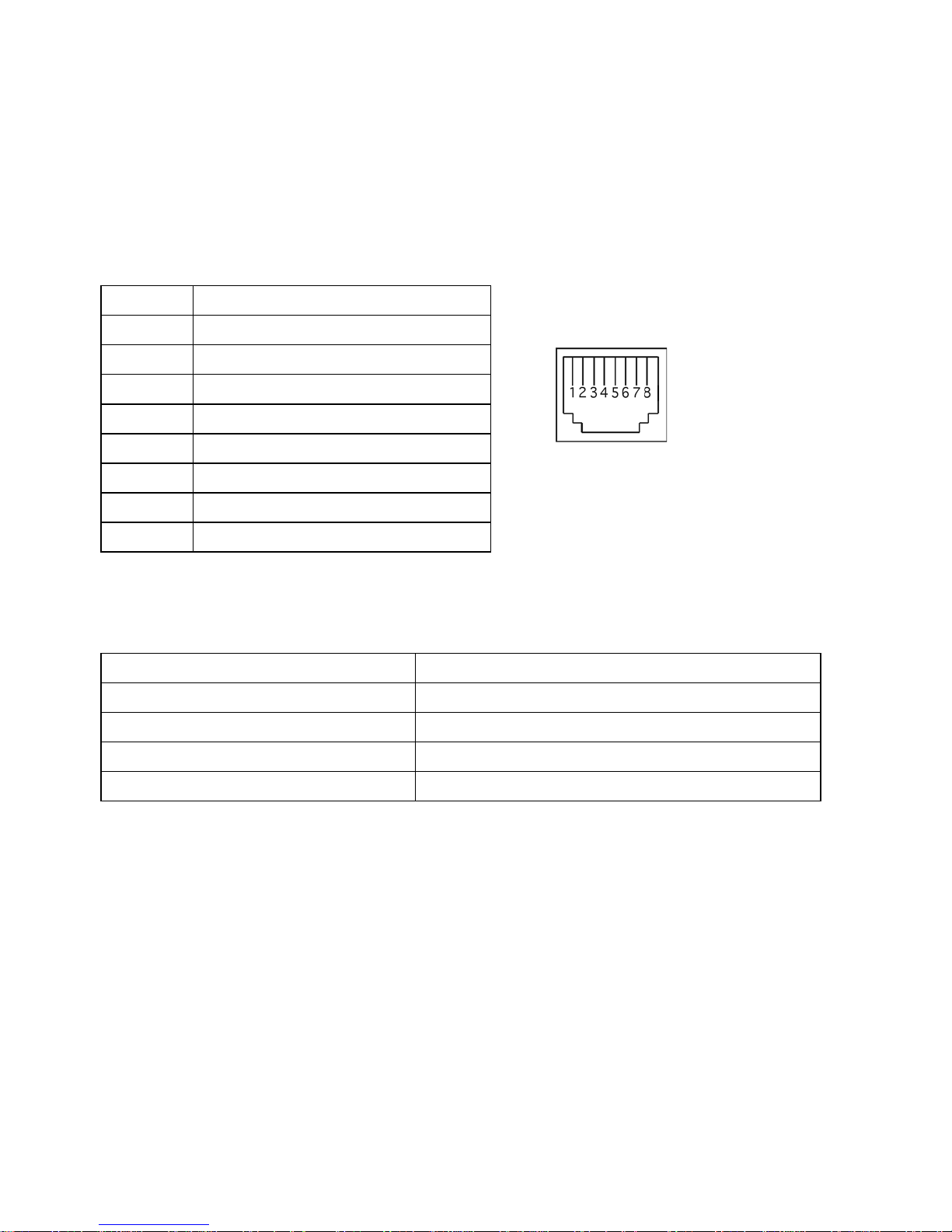
RJ-45 PIN configuration for Ethernet
Physical specification for Ethernet
PIN NO. PIN Assignment
1.
TX +
2.
TX -
3.
RX +
4.
Not Connected
5.
Not Connected
6.
RX -
7.
Not Connected
8.
Not Connected
RJ-45 socket
NOTE: If you use a laptop to connect the Video Server, please set the Power schemes to the „Home/office
Desk” item to get the higher quality of surveillance.
1. Open the Control Panel by clicking Start –> Control Panel.
2. Open the Display Properties by clicking Display –> Display Properties.
3. Click the Screen Saver item.
4. Click the „Power” button.
5. Select „Home/office Desk” under the Power schemes item.
21
6.1 Microsoft Internet Explorer
6.1.1 Connecting the Video Server
1. Start up the Microsoft Internet Explorer, and then follow the steps below to connect the Video Server.
2. Click the URL block at the top of the window.
3. Enter the URL address of the Video Server into the URL block and press the
„Enter” button to enter the home page.
4. Scroll to the bottom of the page, with its five icons, „Image”, „Network”, „System”, „Application”, „SD Card” and
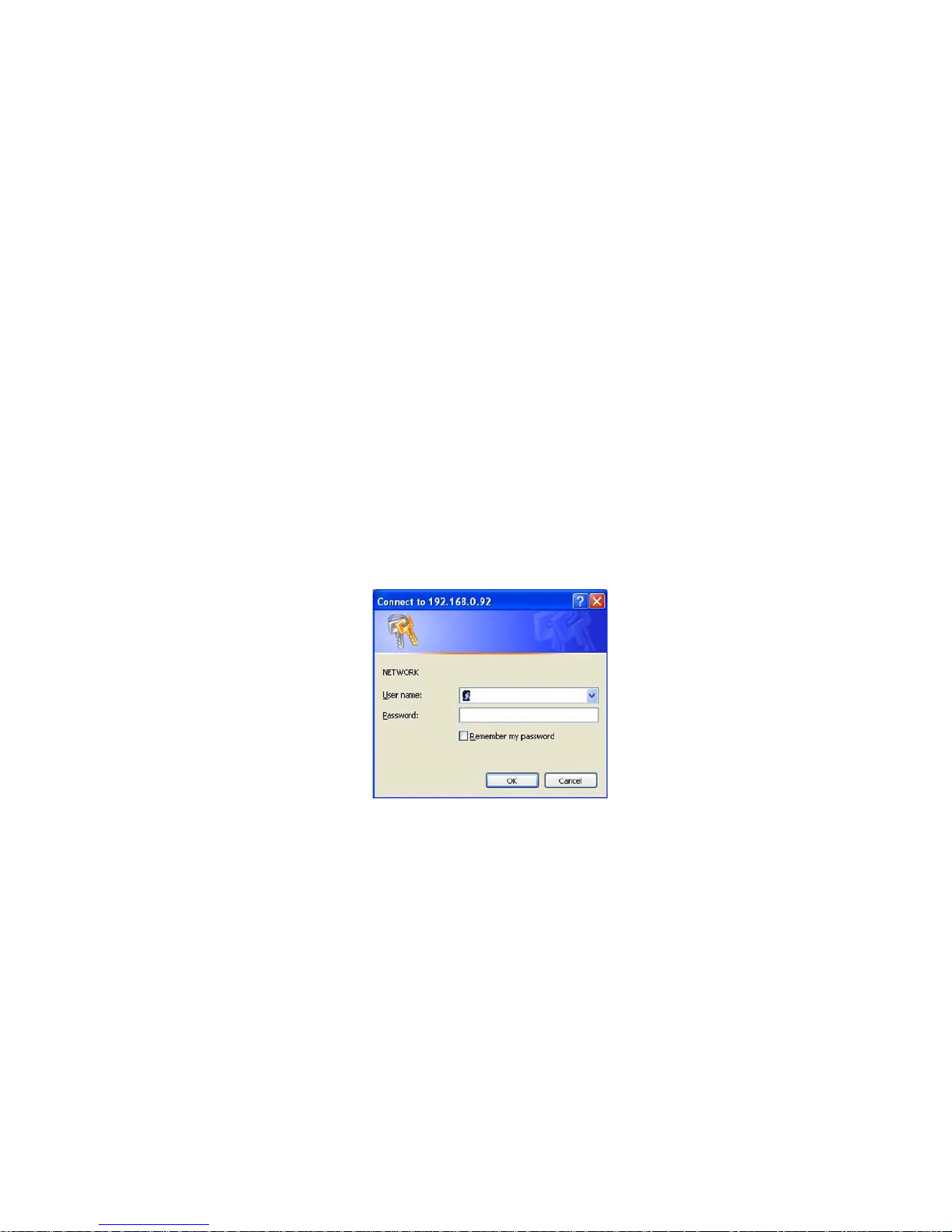
„Pan/Tilt”. Whichever you click, the page headlined „Enter Network Password” will appear.
5. Type in the „User Name” and „Password” in the appropriate spaces.
6. Click the
„OK” button to set your entries, and automatically exit the page.
NOTE: The default „User Name” and „Password” are admin and 9999 respectively.
NOTE: The page headlined „Enter Network Password” is shown below. Please enter the user name and
password of the Video Server when you see it. If either the user name or the password is incorrect,
please check the input data and rectify it if and as necessary.
NOTE: Once authorized succesfully, it will not appear again until you close the window and reconnect it.
NOTE: The initial sequence of proceeding is to type in your IP address and click the „Enter” button to access
the home page. If and when you revise or change data in the „SYSTEM USERS” page, the sequence will
alter to initially show the „Enter Network Password” page.
 Loading...