

Eneo GLS-2101, GLS-2104 Instruction Manual

Instruction Manual
Network 1-channel Video/Audio Server
GLS-2101

Table of Contents
1. PRODUCT FEATURES.........................................................................5
1.1 PRODUCT INSTRUCTIONS..................................................................5
1.2 PRODUCT FEATURES........................................................................5
1.3 TECHNICAL SPECIFICATIONS..............................................................6
2. DESCRIPTION OF THE FRONT/REAR VIEW.......................................8
2.1 FRONT PANEL..................................................................................8
2.2 REAR PANEL....................................................................................9
2.3 THE USB FUNCTION.......................................................................10
3. INSTALLATION ..................................................................................11
3.1 UPDATING SYSTEM SOFTWARE............................................... 11
3.2 VIDEO SERVER SD CARD TROUBLESHOOTING...................................13
4. Network Configuration.......................................................................14
4.1 CABLE CONNECTIONS.....................................................................14
4.1.1 Connect to a computer ........................................................................................ 14
4.1.2 Connect to a LAN Hub (INTRANET)................................................................... 15
4.2 CONFIGURE YOUR VIDEO SERVER NETWORK SETTINGS ....................16
4.2.1 Enable DHCP Function........................................................................................ 16
4.2.2 Set Static IP Address ........................................................................................... 16
4.3 TCP/IP COMMUNICATION SOFTWARE...............................................18
4.4 TCP/IP INSTALLATION.....................................................................19
4.5 TCP/IP CONFIGURATION SETTING ....................................................20
4.6 CONNECTION TESTING....................................................................21
5. Operating Instructions for Image Software and Network.................23
5.1 MICROSOFT INTERNET EXPLORER....................................................24
5.1.1 Connecting the Video Server.............................................................................. 24

5.1.2 Change Image Setting........................................................................................26
5.1.3 Change the Network Setting............................................................................... 28
5.1.4 Change the System Setting................................................................................ 39
5.1.5 Change the Application Setting .......................................................................... 47
5.1.6 View the SD card files......................................................................................... 56
5.1.7 Control the Speed Domes................................................................................... 57
5.1.8 PPPoE & DDNS.................................................................................................. 58
5.2 THE VIDEO SERVER ENEO GL-MANAGER......................................60
5.2.1 Introduction to eneo GL-Manager ...................................................................... 60
5.2.2 Install the eneo GL-Manager in your PC............................................................ 61
5.2.3 VIDEO SERVER software..................................................................................62
5.2.4 Operation............................................................................................................. 65
5.2.4 The Image Viewer............................................................................................... 82
6. ADVANCED OPERATION...................................................................83
7. SPECIFICATIONS...............................................................................87
8. Functions of client PC.......................................................................88
APPENDIX 1. –Register as a DDNS member ........................................89
APPENDIX 2. –FAQ................................................................................93

Safety Instructions / Maintenance
• Read these safety instructions and the operation manual first before you install and
commission the unit.
• Keep the manual in a safe place for later reference.
• The system may only be commissioned and maintained by personnel authorized to do this
and it must only be carried out in accordance with relevant standards and guidelines.
• Never cover the ventilation slots to avoid overheating.
• Never insert metal objects or any other items into the vents. This may permanently damage
the unit.
• Protect your unit from contamination with water and humidity to prevent it from permanent
damage. Never switch the unit on when it gets wet.
Have it checked at an authorized service center in this case.
• Never operate the units outside of the specifications as this may prevent their functioning.
• Do not operate the unit beyond their specified temperature, humidity or power ratings.
Operate the unit only at a temperature range of –10°C to +40°C and at a humidity of
max. 80%.
• The unit should be protected against excessive heat, dust, damp and vibration.
• Do not place any heavy objects on the unit.
• To disconnect the power cord of the unit, pull it out by the plug. Never pull the cord itself.
• Pay attention when laying the connection cable and observe that the cable is not subject to
heavy loads, kinks, or damage and no moisture can get in.
Do not attempt to disassemble the camera board from the dome.
• Contact your local dealer in case of malfunction.
• The connection cable should only be changed by Videor Technical.
• The warranty becomes void if repairs are undertaken by unauthorized persons. Do not
open the housing.
• Maintenance and repair have to be carried out only by authorized service centers. Before
opening the cover disconnect the unit from mains input.
• Only use original parts and original accessories from Videor E. Hartig GmbH.
• Do not use strong or abrasive detergents when cleaning the dome. Use a dry cloth to clean
the dome surface. In case the dirt is hard to remove, use a mild detergent and wipe
gently.
NOTE:
This is a class A digital device.
This digital device can cause harmful interference in a residential area; in this case the
user may be required to take appropriate corrective action at his/her own expense.

1. PRODUCT FEATURES
1.1 Product Instructions
This video server is a user-friendly device. It provides stable, reliable and convenient network
surveillance. It safely downloads automatic video Codec and other components, and lets you very
easily set up the control settings.
The user can access the network to get smooth images in the live mode through the real-time and
synchronized audio/ visual stream provided by the device. The device has a built-in Website Server
providing many Internet functions and protocols, including the MDIX protocol which recognizes
both the normal and crossover cables, either of which can connect up with a video server.
The device also makes it easy for the user to get IP address information since this product supports
the USB interface which helps you get an IP address very easily. You can just open the IE Browser,
then type in the device's IP address to the Browser to access this device.
The device uses the Motion-JPEG compression mode to get good images. You can save any
important images in your device via an SD memory card or a remote client PC. This device can be
connected to an Analog camera, which can't be remotely surveillance except by using this product.
We believe this unit is the right answer to your Network surveillance problems. You will find it
indispensable.
1.2 Product Features
1. Real-time synchronization of the video and audio functions.
2. Supports the Motion-JPEG/ MPEG4 (dual mode) compression mode.
3. The installation of a Codec or execution file is not necessary. The device will automatically
send the Codec or any component to a PC if the latter requires it.
4. Built-in Website Server and network connection.
5. Built-in SD card slot for copying image to SD card.

6. Supports multi-zones motion detection for each channel.
7. Supports 10 users with 3 levels with authority.
8. Supports encryption to warn you if your images have been tampered with.
9. See live images in any network - connected PC.
10. Operation-status record log.
11. Audio function included.
12. Supports the MDIX protocol that recognizes both the normal and crossover cables, either of
which can connect up with a video server.
13. Provides 1-channel video - in to connect an Analog camera.
1.3 Technical Specifications
General
l Image compression: M-JPEG / MPEG4 (dual mode)
l Power supply: DC 12V, 200mA
l Power consumption: 2.5 W
l Operation temperature: 0°C to 50°C
l Storage temperature: -20°C to 60°C
l Operations humidity: 30% to 80 %
Video signal
l Video input x 1: 1.0Vp-p, 75 ohms (BNC unbalanced)
AGC Range: 0.5 ~ 2.0Vpp
Chrominance: 0.286Vpp, +/- 2dB
Color sub-carrier lock range: +/- 200H
l Video output level: 1.0Vpp +/-10%, 75 ohms, composite, negative
(BNC unbalanced)
l Video output frequency: -3dB +/-1dB at 3.58 MHz
l Video output burst level: 286mv (NTSC), 300mv(PAL) +/- 10 %
l Compression resolution: FULL D1: 720 x 480(NTSC), 720 x 576(PAL)
HALF D1: 720 x 240(NTSC), 720 x 288(PAL)
CIF: 352 x 240(NTSC), 352 x 288(PAL)
l Video Fine Tune Contrast, Brightness, Hue, Saturation
Audio signal
l Number of tracks: 1 Channel
l Audio compression: 8 kHz sampling, µ-law
l Audio input: 4.7k ohms, 2.6Vp-p, RCA
l Audio output: 1k ohms, 2.6Vp-p, 100~2k Hz, RCA
l Network Audio Stream Available

Compression
l Resolution: Full D1, Half D1, CIF
l MJPEG Performance: Up to 30(25) FPS
l MJPEG Picture size: 4~64 KB
l MJPEG Watermark: Digital Signature
l MPEG4 Quality: 5 Levels and Customized bit-rate (from 64 Kbps to 8 Mbps)
l MPEG4 Frame rate: 30(25)/ 24/ 15/ 5 FPS
Network & Serial ports
l Network interface: Ethernet (RJ-45, 10/100M) and MDIX supported
l Network protocol: TCP/IP, DHCP, HTTP, FTP, SMTP, SNTP, DDNS, UPnP, PPPoE
l IP Filter: 7 policies to deny or allow
l Remote Access software: Microsoft Internet Explorer or Client software
l Network API: Supported with SDK & HTTP-API
l Network throughout: 2.0 M Byte/Sec
l Web server access: 8 simultaneous users
l Serial port: RS-485
l USB: USB Slave 1.1
l USB Download rate: < 1MBytes
Alarm And IO
l Alarm In: 1 input, Hi = 5V, Lo = 0 V (Configurable)
l Alarm Out x 1: 1 output, Hi = 5V, Lo = 0 V (20mA)
l Alarm Reset x 1: 1 reset, Hi = 5V, Lo = 0 V (Active)
l Alarm Notice: GPIO output and SD, FTP, SMTP recording
Display
l Display Format at Local: Full
l Display Format at Client: Full
l Display Refresh Rate: 60(50) fps
Feature
l Built in RTC: Yes
l Software Upgrade: SD Card, USB, HTTP or FTP
l Motion Detection: 96 independent blocks with 5 levels sensitivities
l Security: 10 users with 3 level authorities
l Time Stamp: Date/ Time/ Location
l Regulation: CE, FCC, RoHS
Compatible Devices
l SD Card: 32MB ~ 4 GB (SDHC Support)
Panasonic/PQI/Hagiwara/Transcend/SanDisk
l Media File Format: JPEG Snapshot/AVI File
MTBF
l Main : 135,000 Hr
2. DESCRIPTION OF THE FRONT/REAR VIEW
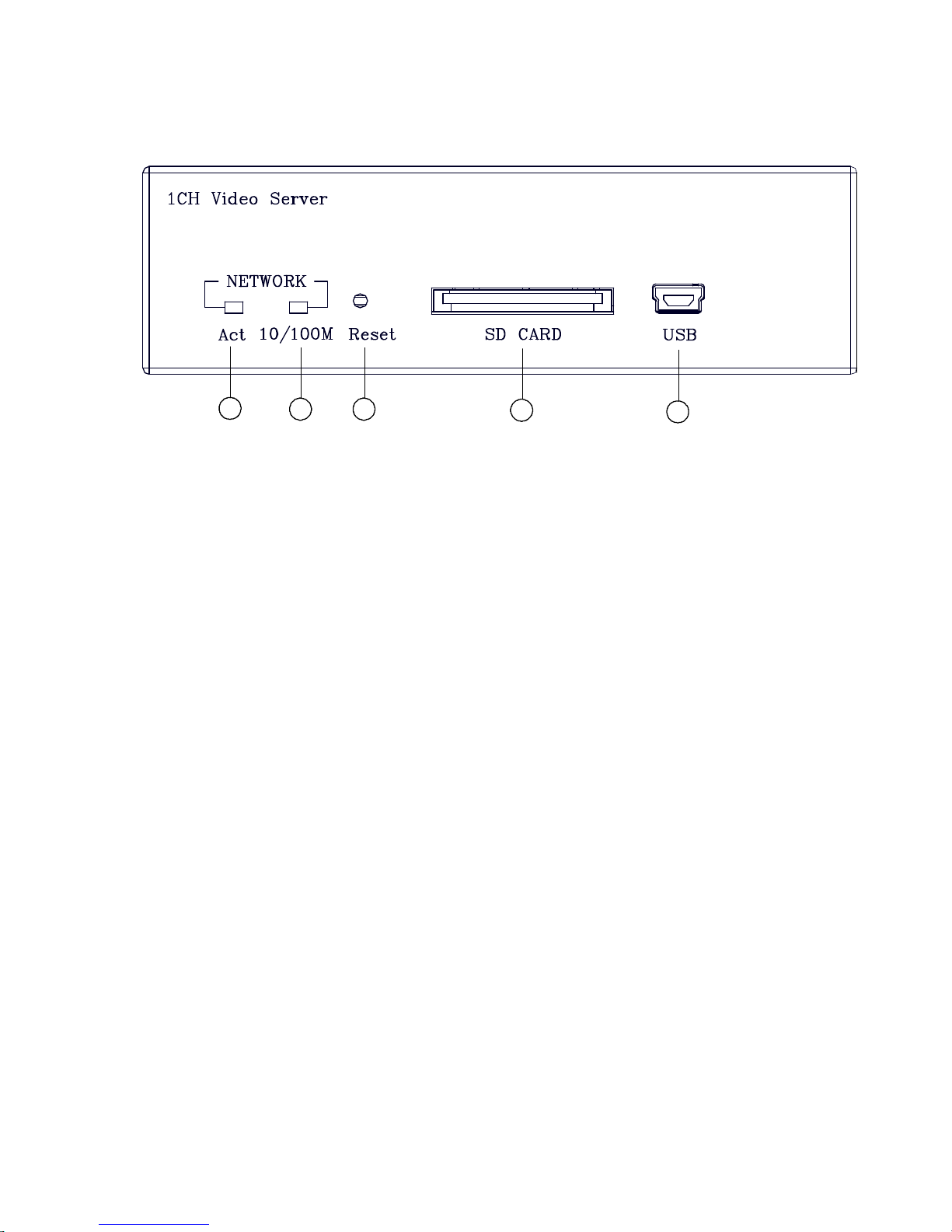
2.1 Front Panel
5
4
32
1
1. Act indicator:
Indicates the network status of the unit. The green light indicates the network is activating.
2. 10/100M indicator:
The green light indicates the network data are transmitting.
3. Reset button:
Recover to factory default.
4. SD CARD Slot:
This is used for system software updating and archiving / accessing critical images.
5. 5pin MINI B Port:
The user can use a USB device cable to connect the Video Server to the USB port on the
PC.
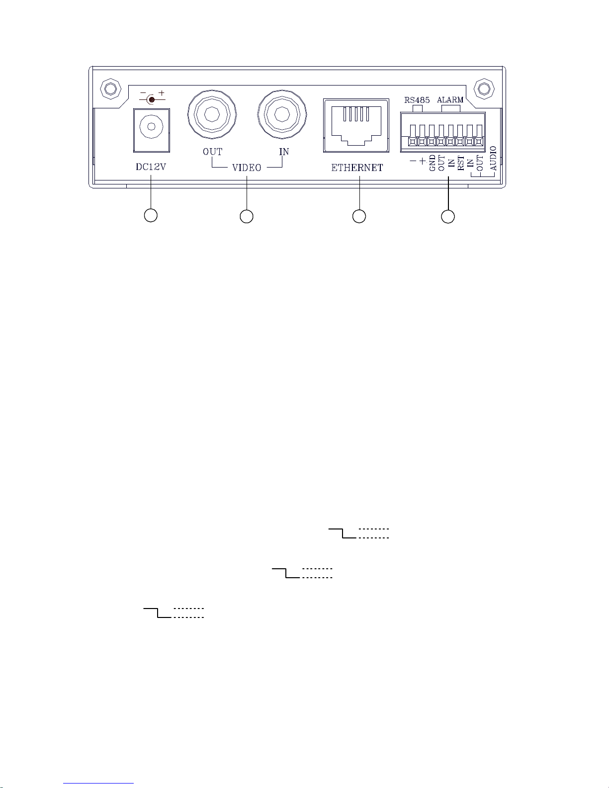
2.2 Rear Panel
4
3
2
1
1. DC jack: The inlet connects to an external power supply. Connect with the 12 V DC
TUV-approved Power Supply; or connect with the UL Listed Class 2 Power Supply or
ITE power supply marked ‘LPS’ or its equivalent.
2. Video in connector: The BNC connector is used to connect to the video output from
the camera. 1 camera can be connected to the connector.
Video out connector: This BNC connector provides a video signal to the main monitor.
3. ETHERNET 10/100 Connector: This is a standard RJ-45 connector for 10/100 Mbps
Ethernet networks. Supports MDI/MDIX.
4. ALARM I/O: This is an 8-PIN connector including the ALARM IN/OUT, ALARM RESET,
GROUND, Audio in/out and RESERVED items for connecting with external devices.
l RS485 pin: D-
l RS485 pin: D+
l ALARM IN (INPUT): This is an alarm input which can be programmed in the menu
system to Normally Open or Normally Closed. (
5V
0V(Active)
)
l ALARM OUT 1(OUTPUT): This is an alarm-output trigger. Connect this to external
devices such as buzzers or lights. (
5V
0V(Active)
)
l ALARM RESET (INPUT): This pin connects to an alarm-clear device for clearing an
alarm. (
5V
0V(Active)
)
l GND: Ground Contact.
l RST: Reset
l AUDIO IN Connector: The connector is used to connect the audio output from a camera
or other devices.
l AUDIO OUT Connector: The connector provides the unit’s audio signal to a speaker or
stereo.
2.3 The USB function
By connecting the Video Server with a PC via the USB connector, the Video Server can provide
different functions.
1. Insert an SD card: As a card reader.
Insert an SD card into the Video Server, then connect to the PC. You might transfer files
between the SD card and the PC. Once you've connected your Video Server to your computer,
the Windows system will detect the connection and ask you what you want to do with your SD
card.
In another words, if the user connects the Video Server with an SD card and the PC via the
USB connector, the Video Server can be used as a normal card reader.
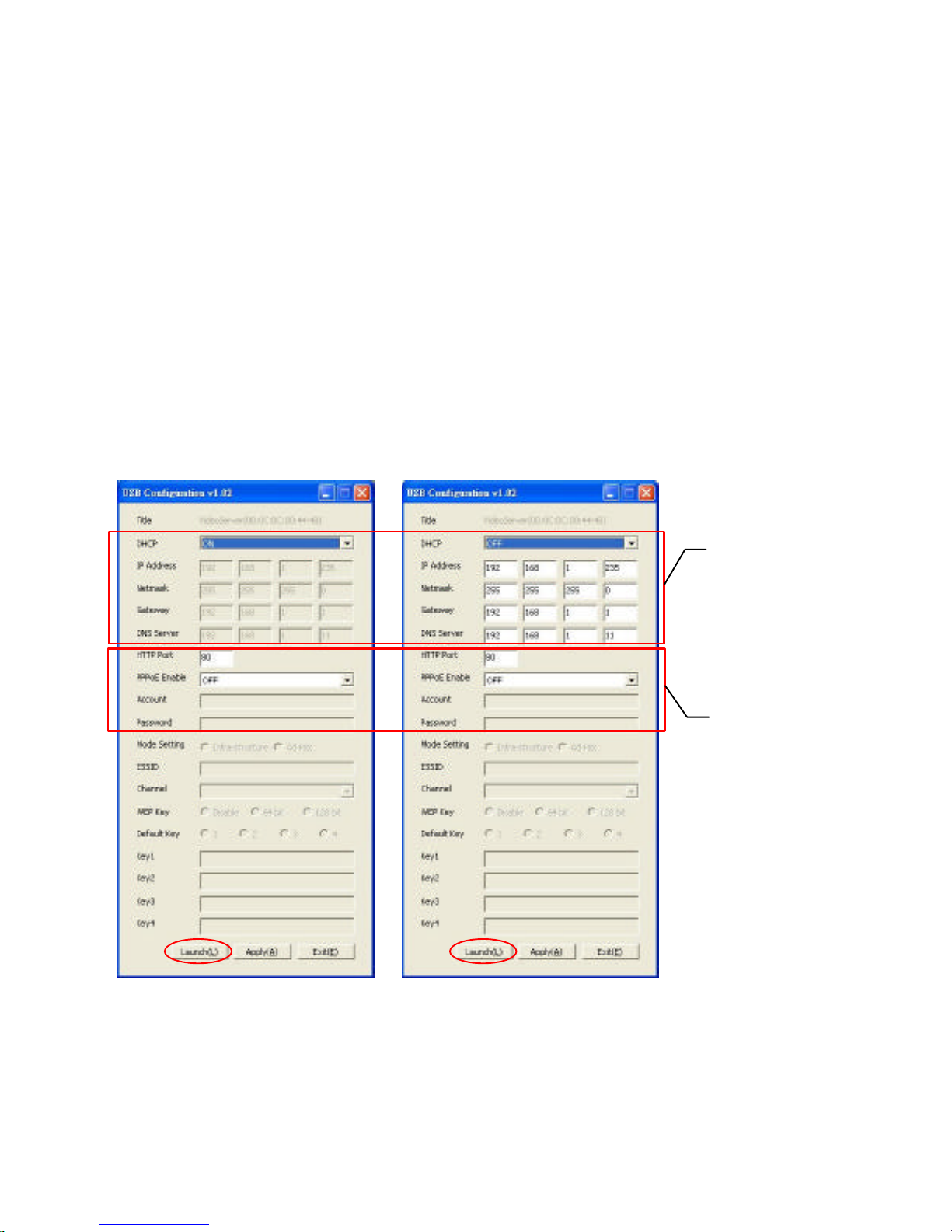
2. As a configuring tool:
By connecting the Video Server with a PC via the USB connector, you can set the Network
and PPPoE functions of the Video Server directly by your PC.
DHCP ON DHCP OFF
NOTE: You can click the “Launch” button to link to the home page of the Video Server.
WARNING: After changing the settings, please click the “Apply” button. All of the
options will be effective after removing the USB connector.
Network
Setting
PPPoE
Setting

3. INSTALLATION
Please follow the instructions below to set up the system.
3.1 UPDATING SYSTEM SOFTWARE
If the system software of the Video Server needs to be upgraded, please take the following steps
to safely process it.
Important: Before carrying out the following procedures, please ensure the SD card is
working and the file of the system firmware is intact
1. Format an SD card using the FAT16 format if it is unformatted; there are no limitations to an SD
card’s capacity.
2. Create a directory named “VSERVER” in the SD card if it does not exist.
3. Copy the file of UPDATE.BIN to the VSERVER-directory.
4. If the Video Server is running, please power it off first.
5. Insert the SD CARD into the Video Server.
6. Remove the Ethernet cable from the RJ-45 port and then power on the Video Server.
7. In 5 to 10 seconds, a message reading "UPDATE PROCESSING" will show up on the screen on
a blue background; if not, please check out steps 1 to 6 carefully or else inform your technical
support while ignoring the following steps.
8. DO NOT power off the Video Server while this update process is running until the message
"UPDATE OK RESET PLEASE" appears on the screen; it might take 15 to 30 seconds to
appear.
9. If the message "UPDATE NG RESET PLEASE" appears rather than "UPDATE OK RESET
PLEASE", please write down the error messages shown on the screen and inform your
technical support, while ignoring the following steps.
10. Power off the Video Server when this update process is finished, then remove the SD card from
the Video Server.
11. Reconnect the Ethernet cable to the RJ-45 port if necessary.

12. Power ON the Video Server and it will work normally if the entire update procedure goes
correctly.
13. Verify the version of the system software.
WARNING:
1. Don’t use FAT32 or NTFS or other file formats in step 1.
2. Steps 1 to 3 have to be done on a PC.
3. Make sure the file of UPDATE.BIN is a correct one in step 3, or the VIDEO SERVER will
not work normally after being updated.
4. If the power of the VIDEO SERVER is suddenly lost in step 8, please remove the SD card
first and turn on the VIDEO SERVER next to test its operation. If the VIDEO SERVER
remains working normally, please go back to step 4; otherwise, please inform your
technical support.
5. In step 10, if the SD card is not removed and the Video Server does not get online as well,
the updating process must be repeated again after rebooting the Video Server.
6. Make sure that the SD card is inserted in a correct position in step 5, or the Video Server
will suffer permanent physical damage.
7. If the message "CSUM ERROR" appears in step 8, it implies a problem in the file of
UPDATE.BIN.
8. Don’t interrupt the process while the unit is updating itself; proceed with an SD card
not including any system software of the unit, or else the unit will crash.

3.2 Video Server SD card Troubleshooting
1. Check if the SD card position is correct or not. Please refer to the manual for the related
information.
2. After powering the Video Server on, correctly insert the SD card, and a little icon of "SD" will
show up in the upper-right corner of the monitor screen. If not, it means the device detection has
failed. Please contact your technical support and ignore the following steps.
3. If no cross sign appears beside the "SD" icon, please go on to the next step. If a cross sign
appears, please check the following:
a. Is it really an SD "Memory" Card?
b. Is this SD card formatted in the FAT16 format?
c. Connect the SD card with a PC and test to see whether the PC can read the data or not.
d. Does this SD card still have the capacity for storing data?
e. Is the SD card set to write?
If all the answers are "yes" but the cross sign still persists, please contact your technical support
and ignore the following steps.
4. Please make sure the function of "SD CARD ENABLE" is activated in the ALARM and
SCHEDULE pages if no cross sign appears beside the "SD" icon on the screen.
5. After recording, read the data on the web page of "sdget.htm". If the data cannot be read through
the network, please read it instead in a PC, check the data stored in the "VSERVER" directory
and contact your technical support regardless of whether there is data or not.
WARNING:
1. Performing this troubleshooting process may need a monitor, a PC, a card reader and
some cables.
2. If the SD card is removed while storing or accessing data, the data will be lost.
3. If there is a cross sign beside the "SD" icon, it means the SD card has been inserted into
the Video Server but cannot perform its writing function. Possible reasons are:
a. It is not an SD memory card.
b. The SD card is unformatted or formatted in a non-FAT16 or non-FAT12 format.
c. The file system is damaged.
d. The capacity of the SD card is full.
e. The SD card is set to be read only.
4. Turn off the power before inserting the SD card. Otherwise the unit may shut down.

4. Network Configuration
4.1 Cable Connections
Please follow the instructions below to connect your Video Server to a computer or a network
and to choose a proper RJ-45 cable configuration for connections.
Physical specifications of the RJ-45 cable for Ethernet
Wire Type Cat. 5 or above
Connector Type RJ-45
Max. Cable Length 100 m
Hub Wiring Configuration Straight through or Cross Over
PC Wiring Configuration Straight through or Cross Over
4.1.1 Connect to a computer
Use a cable to connect directly to a computer.
NOTE: When connecting the PC and the Video Server, the PC and the Video must be
assigned IPs, which must be in the same class type as your network address.
RJ-45
CROSSOVER CABLE
CROSSOVER CABLE PIN CONFIGURATION
LAN CAMERA
TO PC LAN CARD
Normal or crossover cable
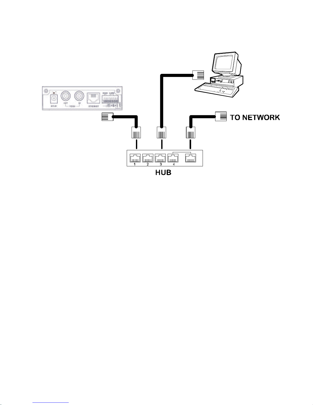
4.1.2 Connect to a LAN Hub (INTRANET)
The RJ-45 PIN configuration for connecting with a LAN Hub is shown below.
RJ-45
LAN CAMERA
TO PC NETWORK CARD
uplink
4.2 Configure Your Video Server Network Settings
Upon connecting with the network hardware, you need to activate the network function and
configure the proper network settings of the Video Server.
4.2.1 Enable DHCP Function
The user can use the USB function (refer to section 2.3) or the Internet Explorer (refer to section
5.1.3) to enable the DHCP function.
This function can only work if the LAN, which the unit is connected to, has a DHCP server. If the
DHCP server is working, the Video Server will obtain an IP address automatically from the DHCP
server. In that case, please skip section 4.2.2 (Set IP address) and follow section 4.3 (TCP/IP
Communication Software).
4.2.2 Set Static IP Address
You need to set an IP address for the unit if the LAN unit can’t access a DHCP server. Otherwise,
please follow the instructions given below:
Set the IP, MASK and GATEWAY. The following is a sample setting.
IP: 192.168.1.X
MASK: 255.255.255.0
GATEWAY: 0.0.0.0

NOTE: When only one unit of the Video Server is connected to a computer or LAN, you
can freely assign an IP address for the Video Server. For example, there is a
range of Video Server IP addresses from 192.168.1.1 to 192.168.1.255. You can
pick one for use from the range of the IP. It’s not necessary to set MASK and
GATEWAY; leave the settings as default.
When a Video Server is connected to a WAN, you must acquire a unique,
permanent IP address and correctly configure the MASK and GATEWAY settings
according to your network architecture. If you have any questions regarding
those settings, please consult a qualified MIS professional or your ISP.
NOTE: When connecting to a network, each connected Video Server must be assigned a
unique IP, which must be in the same class type as your network address. IP
addresses are written as four sets of numbers separated by periods; for example,
192.168.1.1 Therefore, if the connected network is identified as Class C, for
example, the first three sets of numbers of the Video Server IP address must be
the same as the network address. If the connected network is identified as Class
B, the first two sets of numbers of the Video Server IP address must be the same
as the network address. If you have any questions regarding these settings,
please consult a qualified MIS professional or your ISP.
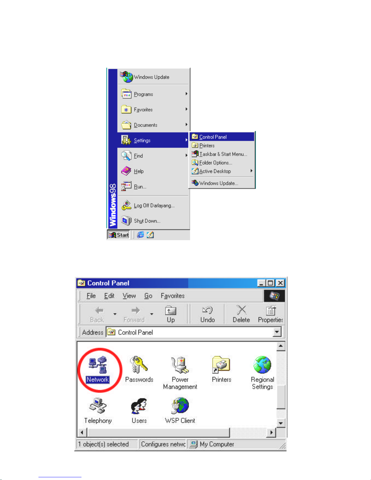
4.3 TCP/IP Communication Software
Follow the procedure below to install the TCP/IP communication program in your computer.
Click the Start menu from your computer, and point to the Settings/Control Panel.
Double click the Network icon to enter the windows.
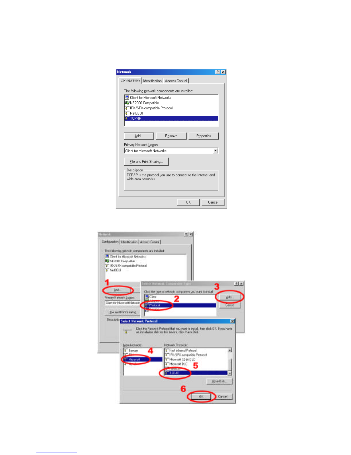
Click the Configuration tag, and check if the TCP/IP is included among the network
components list. If the TCP/IP is included, please process section 4.5. If it is not included, please
follow section 4.4 to install the TCP/IP.
4.4 TCP/IP Installation
During the installation, you will be requested to insert the Windows CD-ROM. After installation,
the PC may be restarted.
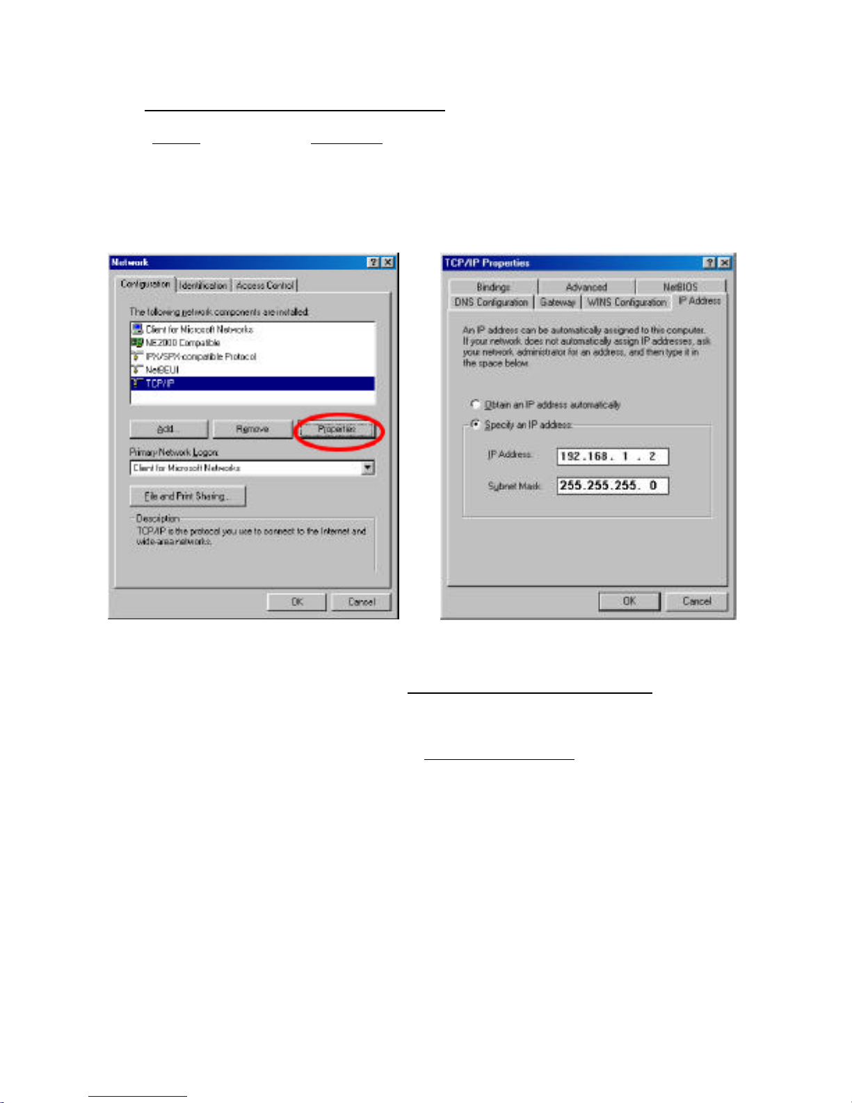
4.5 TCP/IP configuration setting
Click Start ? Settings ? Control Panel ? Network.
Select TCP/IP, and then click Properties.
Before processing the Video Server installation in a WAN, please make sure the Internet
connection works properly. If not, please contact your ISP provider.
?
If you are using a DHCP server, please select Obtain an IP address automatically. Any
assigned IP address for the connected Video Servers must be in the same class type as the
server. If there is no DHCP server, please select specify an IP address and type in the IP
address of your PC. This IP address must be different from other network IP devices but in the
same class type.
NOTE: The IP address of a Video Server in a network must be unique to itself as opposed
to those of the other chosen PCs, but in the same class type.
4.6 Connection Testing
With the previous settings, follow the instructions below to ensure whether you have established
the connection successfully.
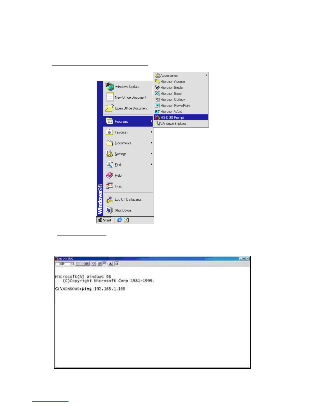
Click Start ? Programs ? MS-DOS Prompt
Type in ping 192.168.1.168, then enter. (See the sample screen below).
** This IP is the Video Server IP address that is assigned for the connected Video Server in step2.
If you receive a response as in the sample screen below, the connection hasn’t been
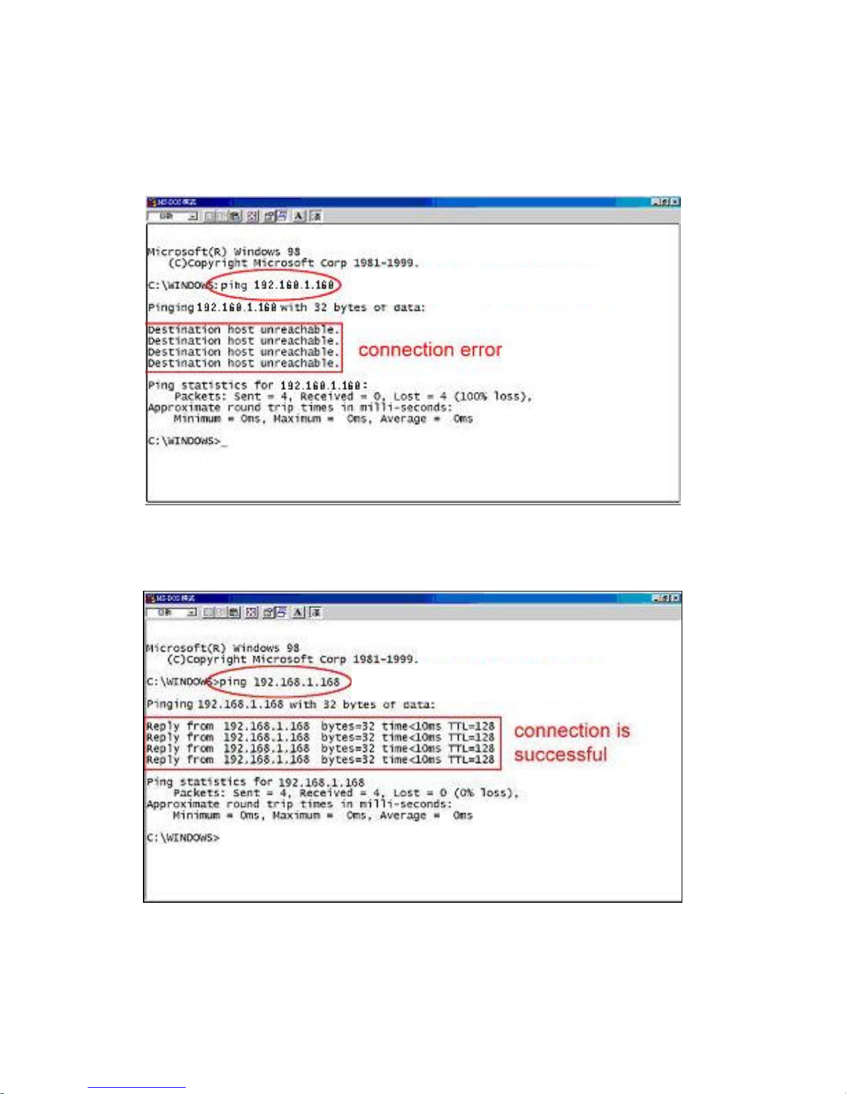
successfully established. Please re-check all the hardware and software installations by
repeating steps 1 to 5. If you still can’t establish the connection after rechecking, please contact
your dealer.
If you receive a response as in the sample screen below, you have successfully made the
connection.
Type Video Server IP address
Type Video Server IP address
5. Operating Instructions for Image Software and Network
Two choices of software are available for linking with the Video Server: (1) the Microsoft Internet
Explorer; and (2) the eneo GL-Manager, a network browser in a PC which provides the functions
of monitoring remote zones or watching recorded data through the TCP/IP protocol. The details
are listed as follows.
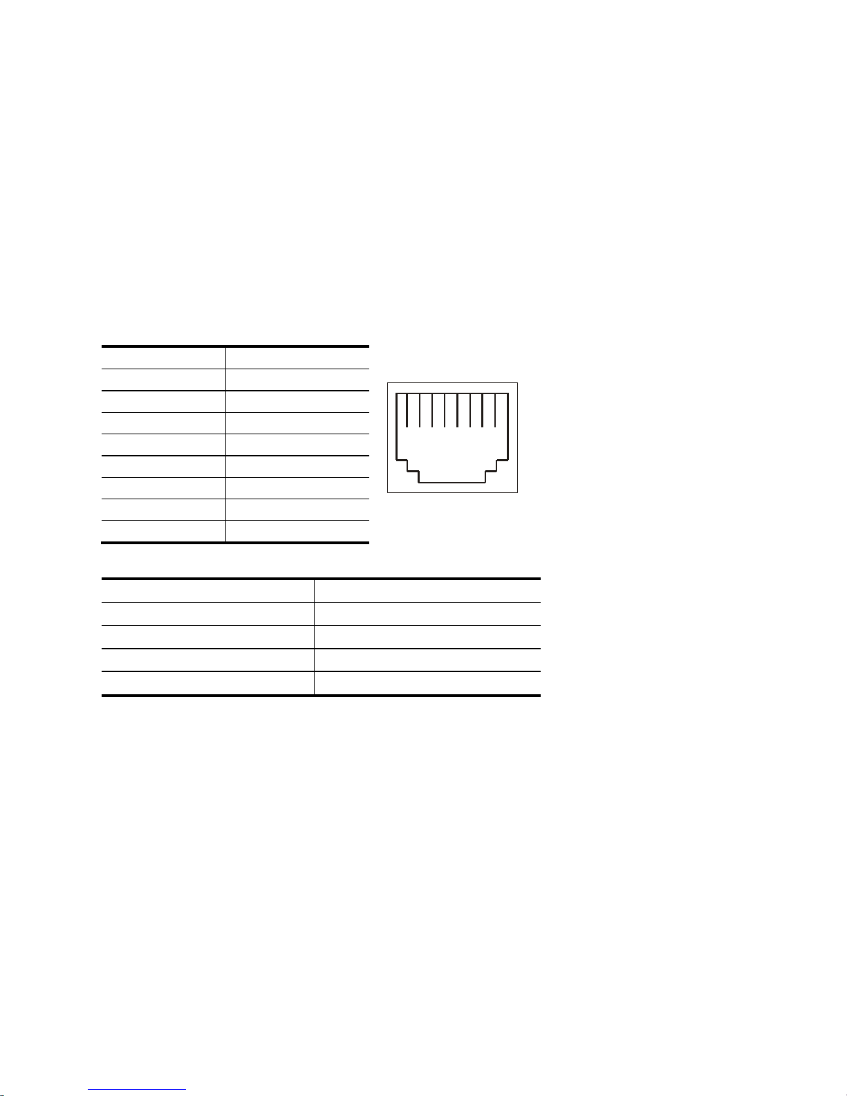
RJ-45 PIN configuration for Ethernet
PIN NO. PIN Assignment
1. TX +
2. TX -
3. RX +
4. Not Connected
5. Not Connected
6. RX -
7. Not Connected
8. Not Connected
Physical specification for Ethernet
Wire type Cat. 5
Connector type RJ-45
Max. cable length 100 M
Hub wiring configuration Straight Through or Cross Over
PC wiring configuration Straight Through or Cross Over
Note: If you use a laptop to connect the Video Server, please set the Power schemes to the
“Home/office Desk” item to get the higher quality of surveillance.
1. Open the Control Panel by clicking Start ? Control Panel.
2. Open the Display Properties by clicking Display ? Display Properties.
3. Click the Screen Saver item.
4. Click the “Power” button.
5. Select “Home/office Desk” under the Power schemes item.
1 2 3 4 5 6 7 8
RJ-45 socket
5.1 Microsoft Internet Explorer
5.1.1 Connecting the Video Server
1. Start up the Microsoft Internet Explorer, and then follow the steps below to connect the
Video Server.
2. Click the URL block at the top of the window.
3. Enter the URL address of the Video Server into the URL block and press the “Enter”
button to enter the home page.
4. Scroll to the bottom of the page, with its six icons, "Image", "Network", "System",
"Application", "SD card" and “Pan/Tilt”. Whichever you click, the page headlined "Enter
Network Password" will appear.
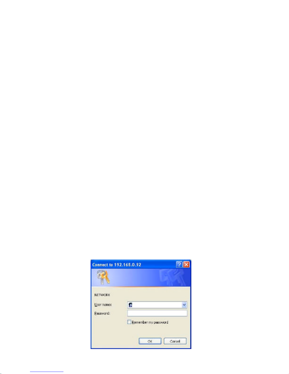
5. Type in the "User Name" and "Password" in the appropriate spaces.
6. Click the “OK” button to set your entries, and automatically exit the page.
NOTE: The default "User Name" and "Password" are admin and 9999 respectively.
NOTE: The page headlined "Enter Network Password” is shown below. Please enter the
user name and password of the Video Server when you see it. If either the user
name or the password is incorrect, please check the input data and rectify it if
necessary.
NOTE: Once authorized successfully, it will not appear again until you close the window
and reconnect it.
NOTE: The initial sequence of proceeding is to type in your IP address and click the "Enter"
button to access the home page. If and when you revise or change data in the "SYSTEM
USERS" page, the sequence will alter to initially show the "Enter Network Password"
page.
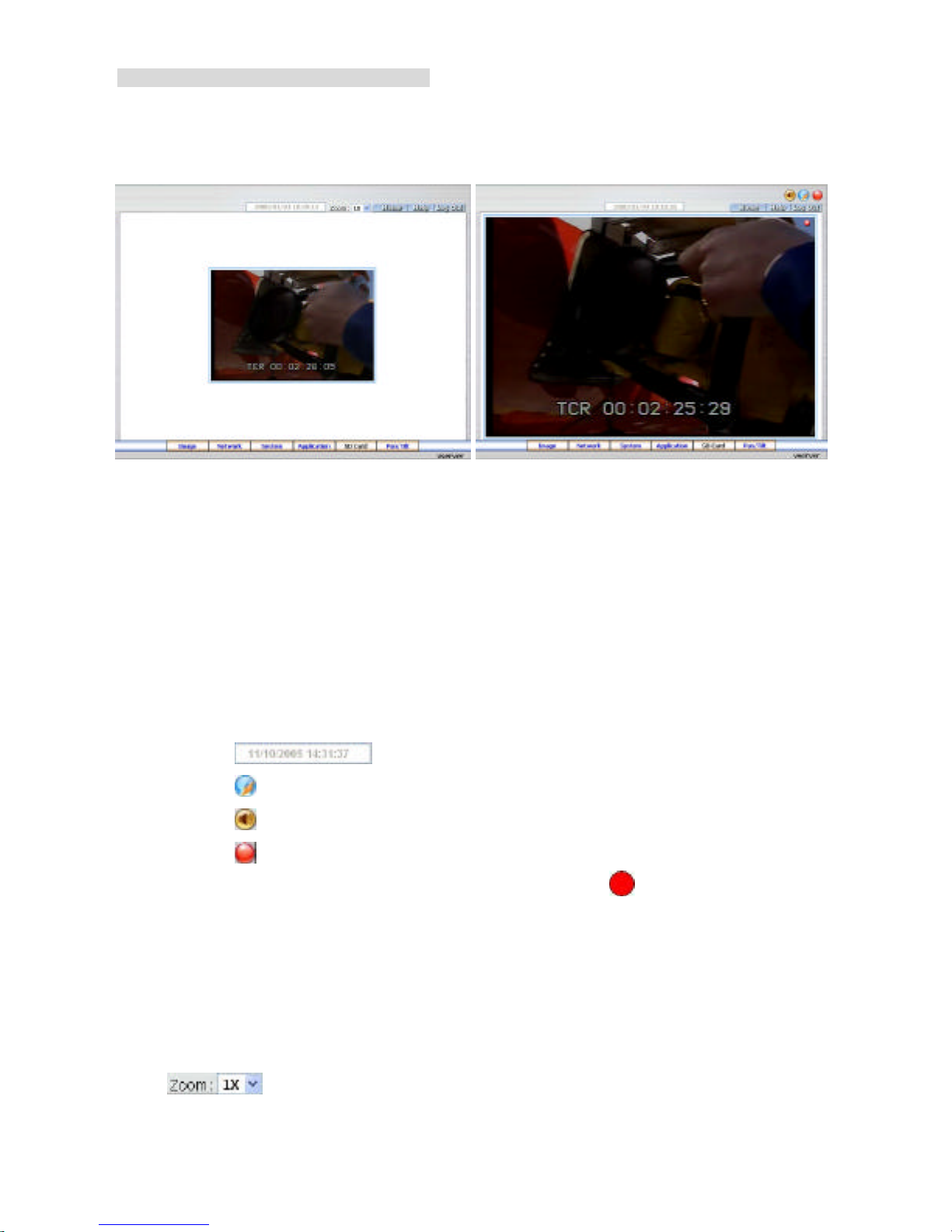
Browsing images from the Video Server
The images from the Video Server will be displayed on the home page while going online with
the Video Server. Some buttons of the home page are provided for further setting.
Homepage of MJPEG mode Homepage of MPEG4 mode
l Click the Image button to enter the Image-setting page.
l Click the Network button to enter the Network-setting page.
l Click the System button to enter the System-setting page.
l Click the Application button to enter the Application-setting page.
l Click the SD card button to open the FILELIST of the MEMORY CARD window, if the SD
card is inserted.
l Click the Pan/Tilt button to control the Pan/Tilt/Zoom settings.
l Click the button to change the time/date display mode.
l Click the button to switch high/low speed network.
l Click the button to play the live audio. Click once again to deactivate.
l Click the button to archive AVI videos into your PC. Click once again to deactivate.
In the recording mode, there will appear a red twinkling icon in the upper-right hand
corner of the image. The AVI file will be saved in the path of c:\ .
l Digital zoom function: Click the left mouse button on the video display area, and it will
show the zoom-in images. Double click the left mouse button to see the maximum size.
Click the right mouse button on the video display area, and it will show the zoom-out
images. Double click the right mouse button to come back to the normal size.
l : Select form the drop-down list to see the normal size and 2X large size
images.

5.1.2 Change Image Setting
Please follow the steps below to change the image setting through the network if necessary.
1. Click the Image button on the home page to enter the image-setting page.
2. Adjust the image setting including “Device Title”, “Channel Title”, “Resolution”, “Quality”
and “Mux/Quad” if necessary.
3. Click the Submit button to submit the new image setting.
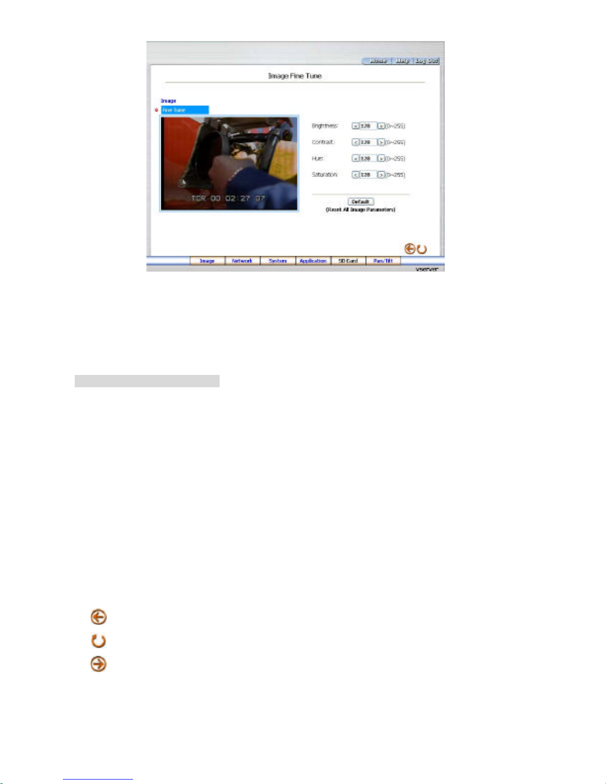
4. Click the Fine Tune button to enter the Image Fine Tune page to set the details of the
device including: “Brightness”, “Contrast’ and “Saturation”. Click the Default button to
reset the channel image settings.
NOTE: The revised image will appear immediately after any change in made.
5. Click the Home button to return to the home page while the new image setting acts on the
images to effect the desired changes instantly. (If the setting has not been changed by the
above steps, any (re)entry onto the home page will find images in their earlier or original
setting.)
Description of function keys:
Device Title: Type in the Video server title in the given space.
Channel Title: Type in the camera title in the given space.
Resolution: Scroll to choose the image resolution from “352*288” or “352*144” (PAL).
Quality: Scroll to choose the image quality out of a spectrum of qualities ranging from
“highest”, ”high”, “medium”, and “low” to “lowest”.
Mux/Quad: Scroll to choose the image mode from “Mux” or “Quad”.
Brightness: Enter your desired quality of image brightness from a spectrum of 0 to 255.
Contrast: Enter your desired quality of image contrast from a spectrum of 0 to 255.
Saturation: Type in the saturation level in the blank (0 to 255).
: Back to the last page.
: Reload the page.
: Go to the next page.
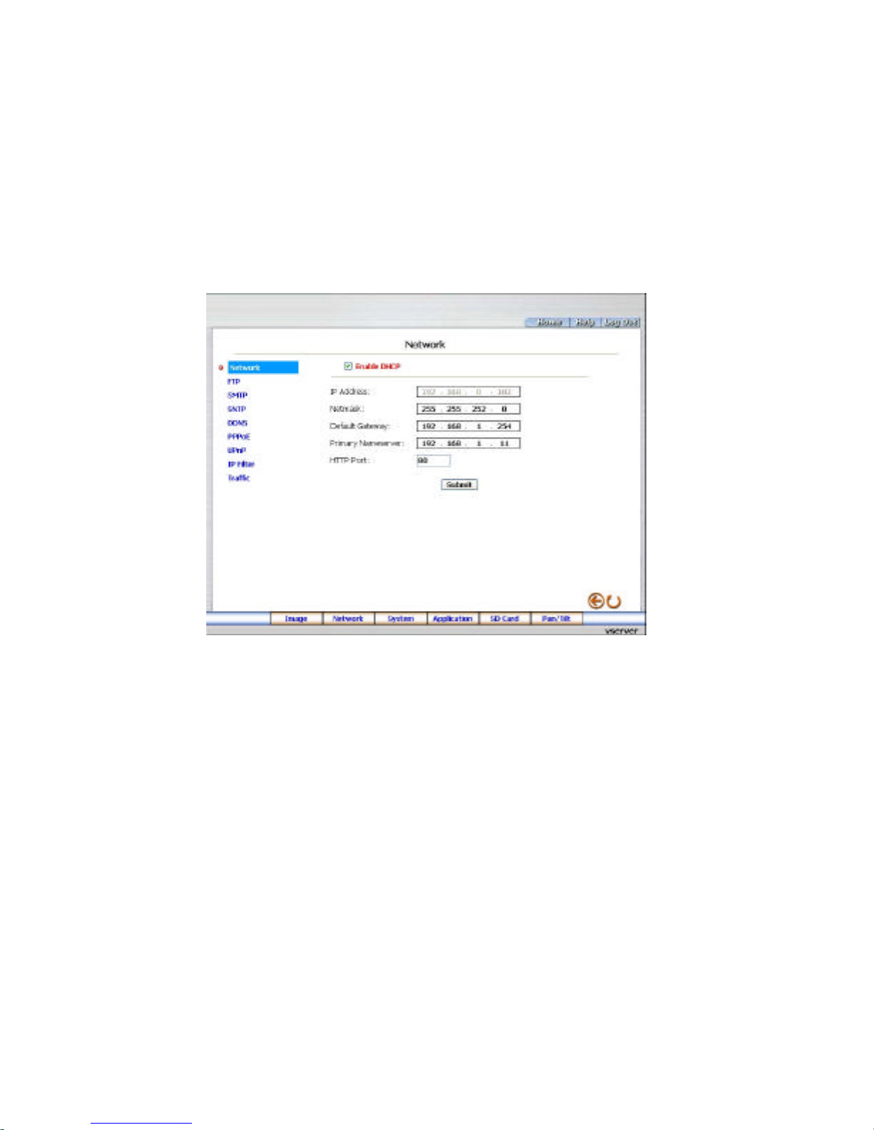
5.1.3 Change the Network Setting
Please follow the steps below to change the network setting through the network if necessary.
l Set the network options and IP address.
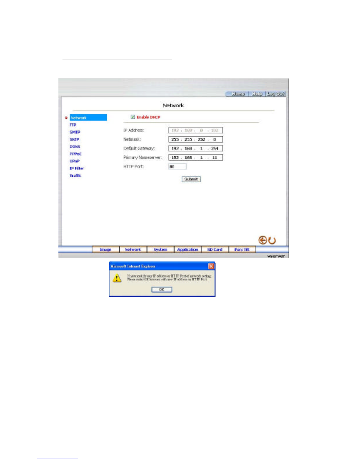
1. Click the Network button in the home page to enter the Network page.
2. A warning message will appear: If you modify any IP
address or HTTP Port of network setting. Please restart the IE browser with the new IP
address or HTTP Port. Click “OK” to continue.
3. The accessible networks here are the “FTP”, the “SMTP”, the “SNTP”, the “DDNS”, the
“PPPoE” and the “IP Filter”.
4. Fill in the “IP Address”, “Netmask”, “Default Gateway”, “Primary Nameserver”, and “HTTP
Port ” if necessary.
5. Click the Submit button to submit the new network setting.
6. Click the Home button to return to the home page.

Description of function keys:
IP Address: Enter the 4-byte IP Address in the appropriate blank space (the value in each
box may be anywhere between 0 and 255). Every Video Server has to own an IP address
to be identified on the network.
Netmask: Fill in the 4-byte Subnet Mask in the required blank spaces (usually any numbers
between 0 and 255). It is used to identify the subnet where the Video Server is sited.
Default Gateway: Type in the 4-byte Gateway in the relevant blank spaces (each unit value
must be between 0 and 255).
Primary Nameserver: Enter the 4-byte DNS Server Address in the blank spaces provided
(each value unit must be between 0 and 255). The DNS Server is in charge of translating
the Domain Name into the IP Address.
HTTP Port: Indicates the specific HTTP Port Number. The default is 80.
Submit: Click to submit the new network setting to the Video Server.
 Loading...