

Eneo GLC-1601 Installation And Operating Manual
1
Installation and Operating Manual
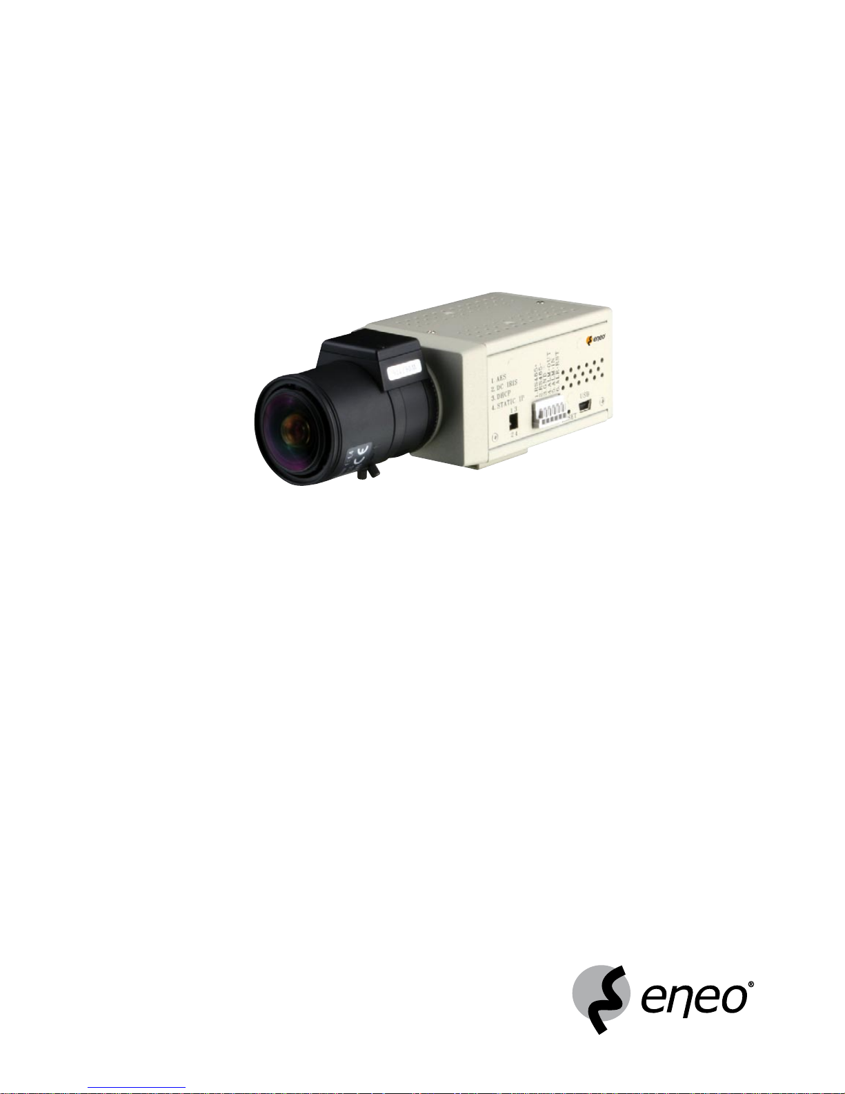
1/3” Day/Night Network Colour Camera, integr. Web Server
GLC-1601

2
Contents
1. Safety Instructions ..............................................................................................................................................3
2. Product Features ................................................................................................................................................
4
2.1 Product Introduction ...........................................................................................................................................
4
2.2 General Description ............................................................................................................................................
4
3. Description of the Front/Rear View ......................................................................................................................
5
3.1 Front Panel and Rear Panel .................................................................................................................................
5
3.2 Flank Panel ........................................................................................................................................................
6
3.3 The USB Function ...............................................................................................................................................
7
3.4 PoE (Power over Ethernet) ..................................................................................................................................
8
4. Installation..........................................................................................................................................................9
4.1 Connecting with an NVR .....................................................................................................................................
9
4.2 Connecting with a DVR .....................................................................................................................................
10
4.3 Connecting with a Multiplexer ..........................................................................................................................
10
4.4 Updating System Software ...............................................................................................................................
11
4.5 IP camera SD Card Troubleshooting .................................................................................................................
12
4.6. Adjustment of Lenses .......................................................................................................................................
13
5. Network Configuration ......................................................................................................................................
14
5.1 Cable Connections ............................................................................................................................................
14
5.2 Configure your IP camera Network Settings ......................................................................................................
16
5.3 TCP/IP Communication Software ......................................................................................................................
17
5.4 TCP/IP Installation ............................................................................................................................................
18
5.5 TCP/IP Configuration Setting .............................................................................................................................
19
5.6 Connection Testing ...........................................................................................................................................
20
6. Operating Instructions for Image Software and Network ...................................................................................
22
6.1 Microsoft Internet Explorer
................................................................................................................................23
6.2 The IP camera eneo GL-Manager .....................................................................................................................
56
7. Advanced Operation .........................................................................................................................................
78
8. Specifications ...................................................................................................................................................81
9. Function of Client PC ........................................................................................................................................
83
10. Dimensional Drawings ......................................................................................................................................
83
APPENDIX 1 - SCAN IP ..............................................................................................................................................
84
APPENDIX 2 - IP Camera UPnP ..................................................................................................................................
87
APPENDIX 3 - The ARP Function ................................................................................................................................
98
APPENDIX 4 - Register as a DDNS Member ...............................................................................................................
99
APPENDIX 5 - MPEG4 Bit Rate Lookup Table of IP Camera ......................................................................................10
3
APPENDIX 6 - FAQ
...................................................................................................................................................104

3
1. Safety Instructions
• Read these safety instructions and the operation manual first before you install and commission the camera.
• Keep the manual in a safe place for later reference.
• Protect your camera from contamination with water and humidity to prevent it from permanent damage.
Never switch the camera on when it gets wet. Have it checked at an authorized service center in this case.
• Never operate the camera outside of the specifications as this may prevent the camera functioning.
• Do not operate the cameras beyond their specified temperature, humidity or power ratings.
Operate the camera only at a temperature range of +5°C to +40°C and at a humidity of max. 80%.
• To disconnect the power cord of the unit, pull it out by the plug. Never pull the cord itself.
• Pay attention when laying the connection cable and observe that the cable is not subject to heavy loads, kinks, or
damage and no moisture can get in.
• Never point the camera towards the sun with the lens open as this may prevent the sensor functioning.
• Do not block ventilation openings.
• The installer is responsible for maintaining the protection class.
• Only use rust-proof screws should be used to mount the housing and camera outside.
• Do not place anything on top of the unit that might spill or fall into it.
• The warranty becomes void if repairs are undertaken by unauthorized persons. Do not open the camera housing.
• Maintenance and repair have to be carried out only by authorized service centers.
Before opening the cover disconnect the unit from mains input.
• Only use original parts and original accessories from Videor E. Hartig GmbH.
• Do not use strong or abrasive detergents when cleaning the dome. Use a dry cloth to clean the dome surface.
In case the dirt is hard to remove, use a mild detergent and wipe gently.
NOTE: This is a class A digital device. This digital device can cause harmful interference in a residential
area; in this case the user may be required to take appropriate corrective action at his/her own
expense.

4
2. Product Features
2.1 Product Introduction
This user-friendly device combines cutting-edge sophistication with practical reliability and convenience, high performance with smooth remote communication. Just plug in the network cable ! You’ll get live streaming Video & Audio
anytime any place ! You’ll have security you can rely on ! The especially high resolution has 520 TV lines, a built-in
web server and a Network interface to connect you with the Internet securely and fast.
Other special features include the masking of personal private images with flexible mask-area positioning and size,
the self-downloading automatic video codec and other components, and the whole unit is very easy to set up. You can
access the network to get smooth images through the real-time and synchronized audio / visual stream provided by
the device, because it supports two compression modes, the MJPEG and the MPEG4 - you can change from one to
the other as you wish. The MPEG4 file format is a very small size file, so it can save more images over a longer time
and can be set extremely fast. The device also has a built-in website server providing many Internet functions and
protocols, including the MDIX protocol which recognizes both the normal and the crossover cables, either of which
can connect up with a IP camera.
We hope this device makes it easier for you to get your IP address information. This unit supports the USB interface
which helps you to very easily get an IP address to open the IE browser: Just type in your IP address to the browser
and you can access your IP camera.
The device can hopefully provide the advanced motion detection function to improve your network surveillance with
both the powerful and enhanced multi-zone and multi-sensitivity modes of detection. We believe this unit is the right
answer to all your network surveillance problems. Try it and you’ll see.
NOTE: Our camera already has a built-in refocus for its Day and Night function. So users don’t need to
have an IR lens in this camera, they can just use a normal lens. If an IR lens is used, the focus will
become blurred.
2.2 General Description
• High Resolution Day&Night (Super HAD CCD)
• Horizontal Resolution of 480 TV Lines (colour)
• Removable IR Cut Filter
• MJPEG and MPEG-4 Video Compression
• Simultaneous Video and Audio Signal Transmission
• E-Mail and FTP Transmission of Important Events
• Integrated Activity Detection
• Ethernet Interface: 10/100Base-TX
• Supports Various Network Environments
• Alarm In/Output, Audio Output
• Upgrade via SD Card, USB Interface and Network
• SD Socket for Local Video Storage by SD Cards
5
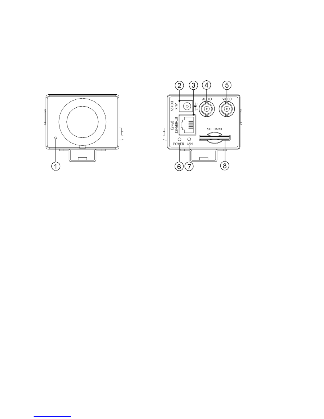
3. Description of the Front/Rear View
3.1 Front Panel and Rear Panel
Front Panel
Rear Panel
1. Microphone
The IP camera has an additional audio function. The device has a microphone built into its front panel which
records sound.
2.
Plug Inlet
A 12VDC inlet that connects to an external power supply.
3. ETHERNET (PoE)
This is a standard RJ-45 connector for 10/100 Mbps Ethernet networks.
PoE (Power over Ethernet) function: Provides power to the device via the same cable as used for the network
connection.
4 AUDIO OUT Connector:
The connector provides the unit’s audio signal to a speaker.
5. VIDEO OUT Connector
The connector provides the unit’s composite video signals to a monitor.
6 POWER indicator
Indicates the power status of the unit. The green light indicates the unit is activating.
The red light indicates the power is on and the SD card cannot be removed.
7 LAN indicator
Indicates the LAN status of the unit. The green light indicates the 100 Mbps Ethernet network is activating.
The red light signals the LAN is data linking.
8 SD CARD slot
This is used for system software updating and archiving / accessing critical images.
6
1. Lens Mount: This IP camera is used with either C or CS mount lens.
2. DIP Switch:
1. AES: Auto electric shutter
2. DC IRIS: Use auto iris (DC drive)
3. DHCP: Turn On / Turn Off use DHCP protocol. If the switch points upwards, the device can
change the setup of network function (enable/disable) via the network.
4. STATIC IP: If the switch points down, the device can’t obtain an IP address from the DHCP
server. This option is needed to configure the network communication settings.
3.2 Flank Panel
Right Flank Panel
Left Flank Panel
3. ALARM I/O: This is a 6-PIN connector including the ALARM IN/OUT, ALARM RESET and GROUND items for
connecting with external devices.
• RS-485 pin: D+
• RS-485 pin: D-
• GND: Ground Contact
• ALARM IN (INPUT): This is an alarm input which can be programmed in the menu system to
Normally Open or Normally Closed. (
5V
0V(Active)
)
• ALARM OUT (OUTPUT): This is an alarm-output trigger. Connect this to external devices such as buzzers or
lights. (
5V
0V(Active)
)
• ALARM RST (RESET): This pin connects to an alarm-clear device for clearing an alarm. (
5V
0V(Active)
)
4. RESET: Recover to factory default.
5.
5 pin MINI USB Port: The user can use a USB device cable to connect the IP camera to the USB port on the PC.
6. ALC VR: Iris control VR
When an auto iris (DC Drive) lens is used, this VR is used to adjust the iris for different lighting environments.
Adjust the VR clock-wise to open the iris and counter-clockwise to close the iris of the camera.
7. IRIS: Auto iris connector
This camera works with a DC drive auto iris lens. Please refer to the pin assignment marked on the camera
when connecting the auto iris lens.
7
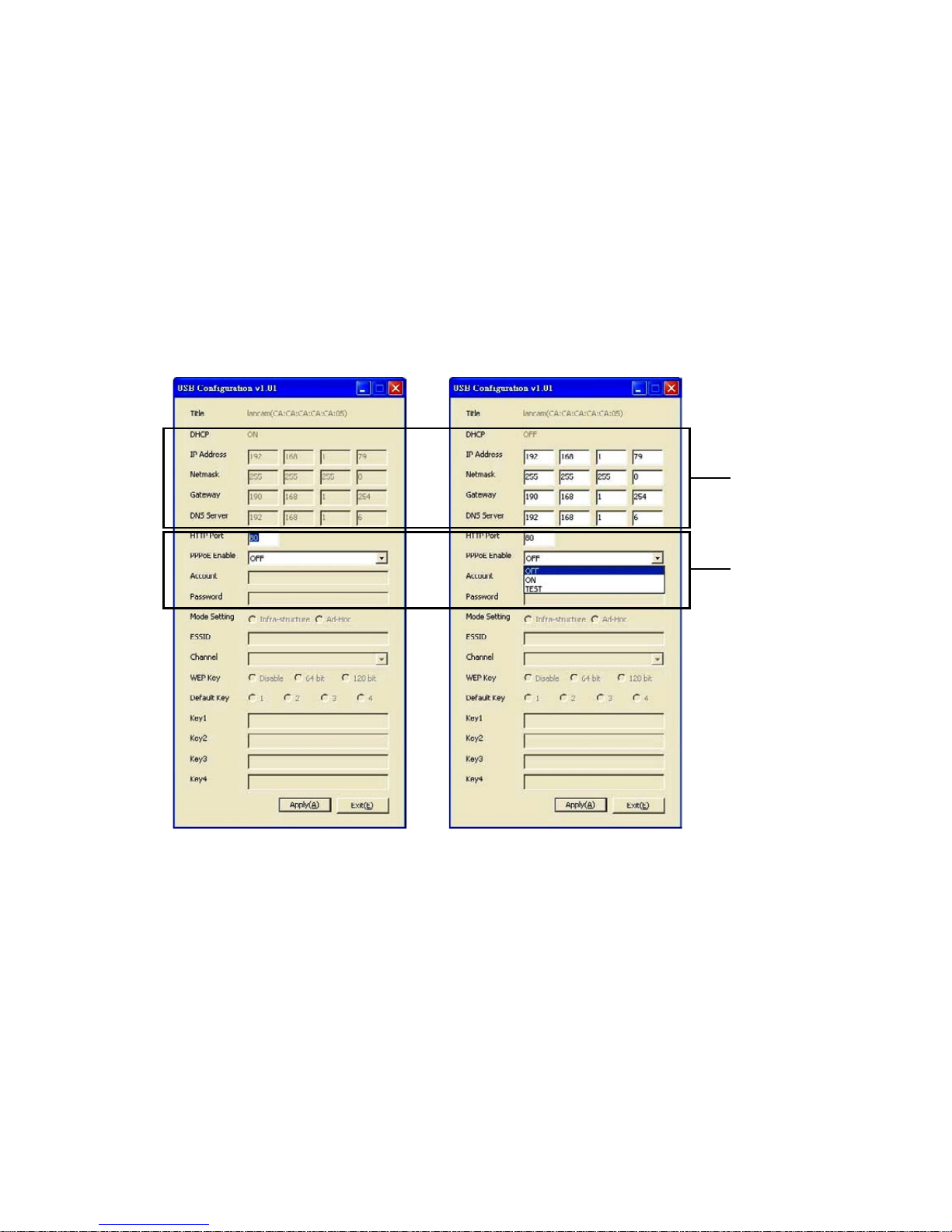
3.3 The USB Function
By connecting the IP camera with a PC via the USB connector, the IP camera can provide two different functions.
1.
Insert an SD card: As a card reader
Insert an SD card into the IP camera, then connect to the PC. You might transfer files between the SD card
and the PC. Once you’ve connected your IP camera to your computer, the Windows system will detect the
connection and ask you what you want to do with your SD card.
In another words, if the user connects the IP camera with an SD card and the PC via the USB connector, the
IP camera can be used as a normal card reader.
2.
Remove an SD card: As a configuring tool
Before using the USB configuration setting page, please remember to remove the SD card or your PC will read
the SD card and won’t show this window.
Network
Setting
PPPoE
Setting
DHCP ON
DHCP OFF
WARNING: After changing the settings, please click the „Apply” button. All of the options will be effective
after removing the USB connector.
8
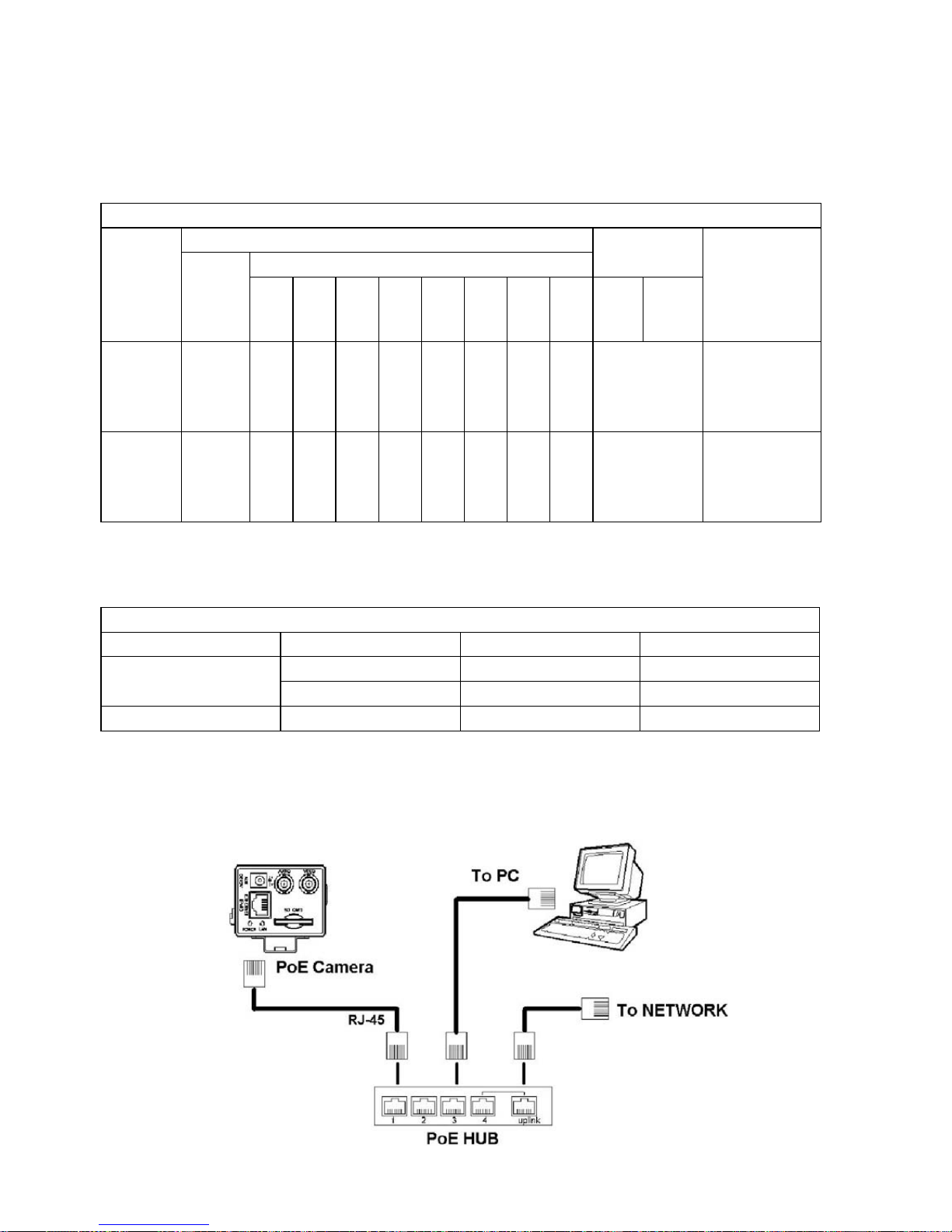
3.4 PoE (Power over Ethernet)
These technologies will enable the development of new networked appliances, by providing power as well as data
over existing Ethernet cables.
The Summary Comparison of PoE Standards (Table 1) is listed as follows.
Connect to a PoE HUB
The Standard RJ-45 PIN configuration for connecting with a PoE HUB is shown below.
Table 1. Summary Comparison of PoE Standards
STANDARD
SOURCE
LOAD
REMARKS
Source
Voltage
Ethernet RJ-45 connector pin number *
1 2 3 4 5 6 7 8
Load
Voltage
DC Load
Connec-
tor
IEEE
802.3af
using data
pairs
48VDC,
protected
RX,
DC+
RX,
DC+
TX,
DC-
spare spare
TX,
DC-
spare spare (embedded)
Industry Standard
for embedded PoE
IEEE
802.3af
using spare
pairs
48VDC,
protected
RX RX TX DC+ DC+ TX DC- DC- (embedded)
Industry Standard
for embedded PoE
The compatible PoE Hubs (Table 2), which can be used with the unit, are shown in the tables below.
Table 2. Compatible PoE HUB
Manufacturer Model Port Note
PLANET
FSP-804P 4 Port PoE HUB
POE-151 1 Port PoE HUB
D-Link DWL-P200 1 Port PoE HUB
9
4. Installation
Please follow the instructions and the diagram below to set up the system.
NOTE: The IP camera is linked by its Video Out connection via a BNC connector to a monitor’s Video In
connection. If this connection is there, you can see some information on the monitor screen, such as
the IP camera factory default Static IP address (192.168.1.168). But the IP camera Static IP
address can only appear if there is a connection between the IP camera and another device.
If there is no such connection, the IP camera factory default Static IP address will not appear on
the monitor screen.
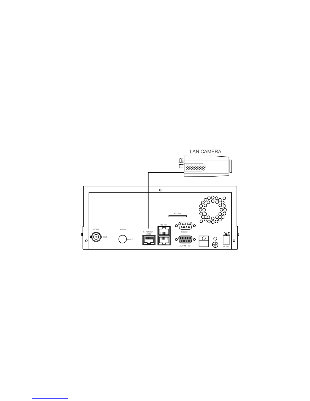
4.1 Connecting with an NVR
Use a crossover LAN cable to connect directly to an NVR.
CONNECT TO ETHERNET
RJ-45 CONNECTOR
CONNECT TO
NVR ETHERNET PORT
10
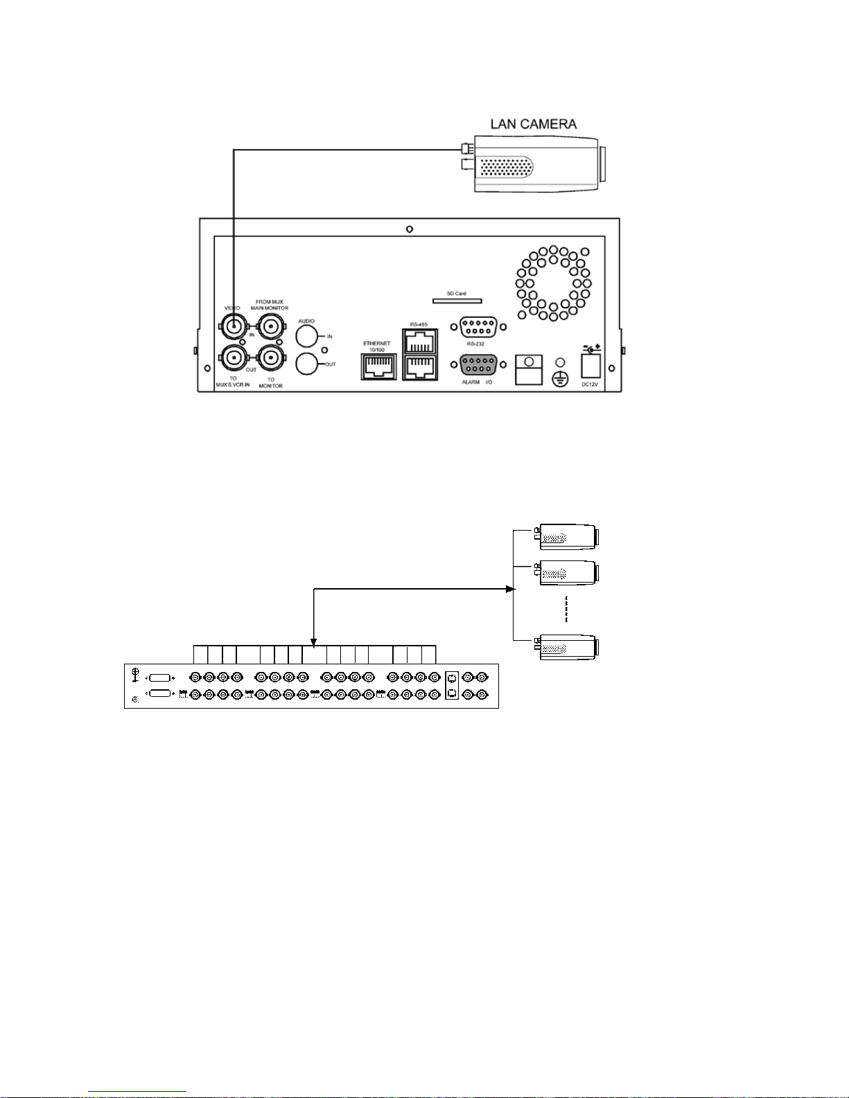
CONNECT TO VIDEO OUT
BNC CONNECTOR
CONNECT TO DVR VIDEO IN
4.2 Connecting with a DVR
TO LAN Camera VIDEO OUT
BNC CONNECTOR
IP camera 1
IP camera 2
IP camera 16
4.3 Connecting with a Multiplexer

11
4.4 Updating System Software
If the system software of the IP camera needs to be upgraded, please take the following steps to safely process it.
Important: Before carrying out the following procedures, please ensure the SD card is working and the file
of system firmware is intact.
1. Format an SD card using the FAT16 format if it is unformatted; there are no limitations to an SD card’s capacity.
2. Create a directory named LANCAM in the SD card if it does not exist.
3. Copy the file of UPDATE.BIN to the LANCAM-directory.
4. If the IP camera is running, please power it off first.
5. Insert the SD CARD into the IP camera.
6. Remove the Ethernet cable from the RJ-45 port and then power on the IP camera.
7. In 5 to 10 seconds, a message reading „UPDATE PROCESSING” will show up on the screen on a blue back-
ground; if not, please check out steps 1 to 6 carefully or else inform your technical support while ignoring the
following steps.
8. DO NOT power off the IP camera while this update process is running until the message „UPDATE OK RESET
PLEASE” appears on the screen; it might take 15 to 30 seconds to appear.
9. If the message „UPDATE NG RESET PLEASE” appears rather than „UPDATE OK RESET PLEASE”, please write
down the error messages shown on the screen and inform your technical support, while ignoring the following
steps.
10. Power off the IP camera when this update process is finished, then remove the SD card from the IP camera.
11. Reconnect the Ethernet cable to the RJ-45 port if necessary.
12. Power ON the IP camera and it will work normally if the entire update procedure goes correctly.
13. Verify the version of the system software.
WARNING:
1. Don’t use FAT32 or NTFS or other file formats in step 1.
2. Steps 1 to 3 have to be done on a PC.
3. Make sure the file of UPDATE.BIN is a correct one in step 3, or the IP camera will not work normally after
being updated.
4. If the power of the IP camera is suddenly lost in step 8, please remove the SD card first and turn on the
IP camera next to test its operation. If the IP camera remains working normally, please go back to step 4;
otherwise, please inform your technical support.
5. In step 10, if the SD card is not removed and the IP camera does not get online as well, the updating
process must be repeated again after rebooting the IP camera.
6. Make sure that the SD card is inserted in a correct position in step 5, or the IP camera will suffer
permanent physical damage.
7. If the message „CSUM ERROR” appears in step 8, it implies a problem in the file of UPDATE.BIN.
8. Don’t interrupt the process while the unit is updating itself; proceed with an SD card not including any
system software of the unit, or else the unit will crash.

12
4.5 IP camera SD Card Troubleshooting
1. Check if the SD card position is correct or not. Please refer to the manual for the related information.
2. After powering the IP camera on, correctly insert the SD card, and a little icon of „SD” will show up in the
upper-right corner of the monitor screen. If not, it means the device detection has failed. Please contact your
technical support and ignore the following steps.
3. If no cross sign appears beside the „SD” icon, please go on to the next step. If a cross sign appears, please
check the following:
a. Is it really an SD „Memory” Card?
b. Is this SD card formatted in the FAT16 format?
c. Connect the SD card with a PC and test to see whether the PC can read the data or not.
d. Does this SD card still have the capacity for storing data?
e. Is the SD card set to write?
If all the answers are „yes” but the cross sign still persists, please contact your technical support and ignore
the following steps.
4. Please make sure the function of „SD CARD ENABLE” is activated in the ALARM and SCHEDULE pages if no
cross sign appears beside the „SD” icon on the screen.
5. After recording, read the data on the web page of „sdget.htm”. If the data cannot be read through the network,
please read it instead in a PC, check the data stored in the „LANCAM” directory and contact your technical
support regardless of whether there is data or not.
WARNING:
1. Performing this troubleshooting process may need a monitor, a PC, a card reader and some cables.
2. If the SD card is removed while storing or accessing data, the data will be lost.
3. If there is a cross sign beside the „SD” icon, it means the SD card has been inserted into the
IP camera but cannot perform its writing function. Possible reasons are:
a. It is not an SD memory card.
b. The SD card is unformatted or formatted in a non-FAT16 or non-FAT12 format.
c. The file system is damaged.
d. The capacity of the SD card is full.
e. The SD card is set to be read only.
4. Turn off the power before inserting the SD card. Otherwise the unit may shut down.
13
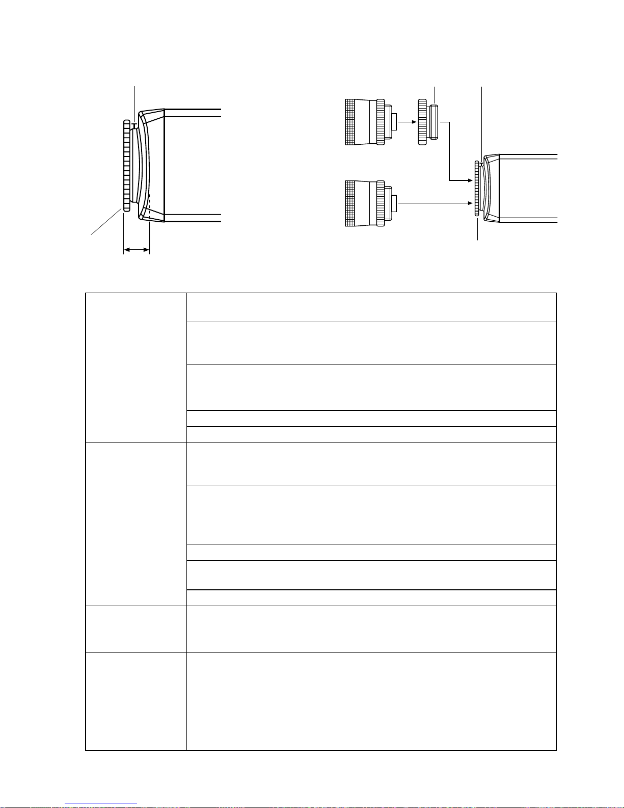
L
M
AL
K
M
L
C mount lens
CS mount lens
4.6. Adjustment of Lenses
Adjustment of flange
focus for fixed focus
lenses
This adjustment (distance between lens casing and sensor surface) is required if a sharp
definition cannot be obtained with the lens focussing, or in order to adjust the
∞ position
To obtain a sharp definition, point the camera at an object which is at least 2000 times
further away from the front of the lens than the focal length. (If the focal length is 7.5mm,
the object must be at least 15m distant from the camera).
Open the aperture fully and set the focus to
∞ (infinite).
If the lens has automatic exposure control, select a dark object, or better use an ND filter
(64-x) to ensure that the aperture is fully open.
Undo set screw
M. Turn the lens with the CS mount connection until the definition is sharp.
When finished, retighten screw
M.
Adjustment of flange
focus for variable
focus lenses
To obtain a sharp definition, point the camera at an object which is at least 5 times the
minimum lens distance (MOD) of the lens. (If this is 1m, the object must be at least 5m
distant from the camera).
Open the iris fully and set the lens to the maximum tele position and focus with the focus
ring.
If the lens has automatic iris control, select a dark object (or use an ND filter, 64-x)
to ensure that the iris is fully open.
Set the lens to the maximum wide-angle position.
Undo set screw
M and turn the C/CS ring on the camera until an optimal sharpness is
reached. Repeat the process for checking purposes, if necessary.
When finished, retighten screw
M.
Note
The value stated in the diagram as AL (depth of thread of the lens with CS mount:
<- 5mm) must be observed. The camera may be damaged if this value is exceeded.
When installing a lens with CS mount, never use the C-mount adapter ring.
Addition when using
cameras for day/
night application
Even if the lens is IR corrected (0-focus shift), a minor flange focus is possible between
visible light and IR light.
If there is a day/night application with IR illumination, the flange focus should be set under
IR light conditions. This is because the iris is generally opened when used at night due
to the poor level of light and low depth of focus. During the day, the iris is continuously
closed further, there is a greater depth of focus and the difference in the flange focus is
compensated.

14
Explanation of terms for iris setting
AGC (automatic gain
control)
This starts tooperate when the light intensity is insufficient to deliver a full video signal
(1Vp-p). The greater the gain, the greater the signal noise in the picture. It is generally
activated between 0.8 and 1.0Vp-p.
White clip
Signal limitation at high image amplitudes. The white clip value generally lies between
1.1 and 1.2 Vp-p.
AES (automatic
shutter control)
This automatically controls the shutter times, it starts when the light intensity becomes
stronger and the signal would otherwise be limited/over-regulated by the white clip
feature. Automatic shutter control is mainly applied for manual lenses.
If a camera is operated with controlled lenses, regardless of whether DC or AI, the AES
must be switched off. Problems arise if this is not done because both control systems
try to steer the volume of light for the camera. As the AES generally reacts faster, the iris
remains fully opened and the shutter resumes the control work, which produces major
drawbacks. As the iris is open, the depth of focus is very low. When shutter times are
short, this can cause a smear effect (bright, vertical stripes in light parts of the picture).
Iris adjustment
The working point of the iris should always be above the AGC start and below that of the
white clip. This range is very small with some cameras, making it difficult to adjust the
lens. It is therefore advisable to switch off the AGC (if possible) when adjusting the iris.
Once the lens has been focussed, the AGC must be switched back on (only for cameras
which allow the AGC to be switched off).
In the case of DC lenses, the working point of the iris is adjusted at the camera’s level
potentiometer (the AI amplifier is built into the camera).
In the case of AI lenses, the level potentiometer is located on the lens (the AI amplifier is
built into the lens).
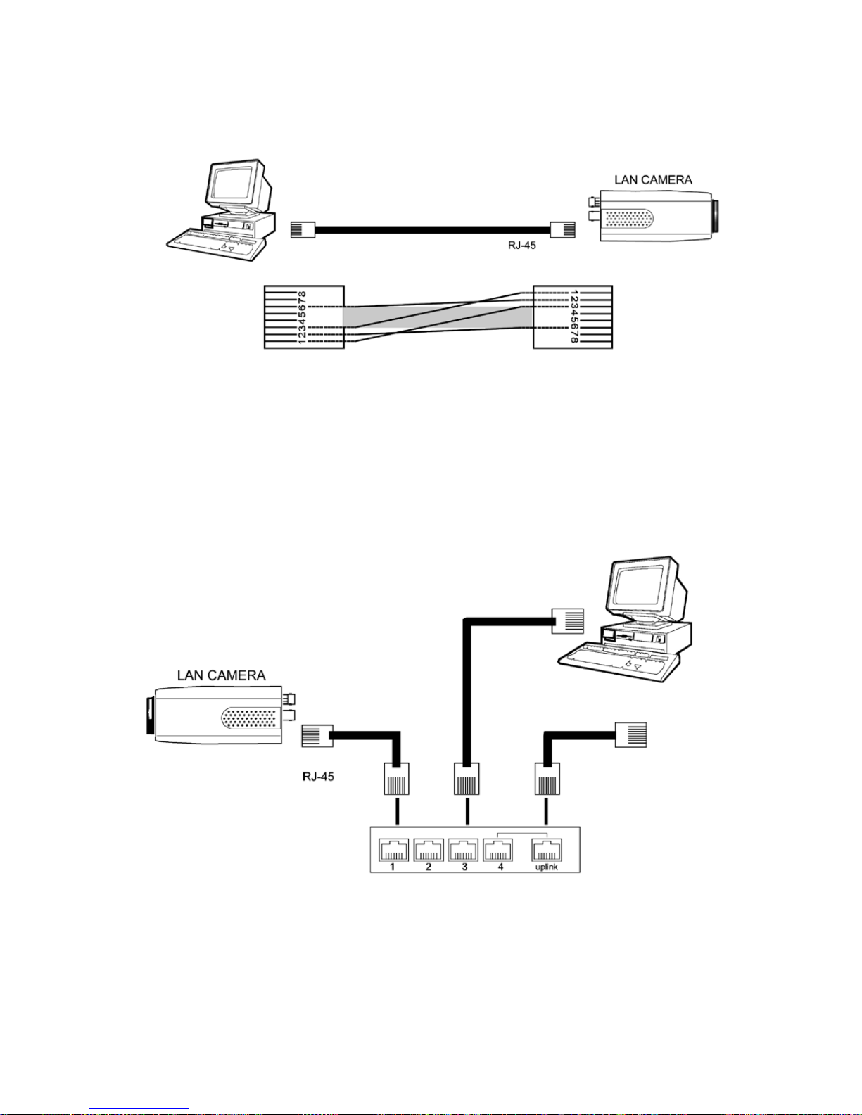
5. Network Configuration
5.1 Cable Connections
Please follow the instructions below to connect your IP camera to a computer or a network and to choose a proper
RJ-45 cable configuration for connections.
Physical specification of RJ-45 cable for Ethernet
Wire Type Cat. 5
Connector Type
RJ-45
Max. Cable Length
100m
Hub Wiring Configuration
Straight Through
PC Wiring Configuration
Straight
15
5.1.1 Connect to a Computer
Use a straight LAN cable to connect directly to a computer.
CROSSOVER CABLE PIN CONFIGURATION
CROSSOVER CABLE
TO PC LAN CARD
5.1.2 Connect to a LAN Hub (INTRANET)
The RJ-45 PIN configuration for connecting with a LAN Hub is shown below.
TO NETWORK
TO PC NETWORK CARD
HUB

16
5.2 Configure your IP camera Network Settings
Upon connecting with the network hardware, you need to activate the network function and configure the proper
network settings of the IP camera.
5.2.1 Enable DHCP Function
This function can only work if the LAN, which the unit is connected to, has a DHCP server. If the DHCP server is
working, please move the dip switch points up to 3 on the flank panel; now the IP camera will obtain an IP address
automatically from the DHCP server. In that case, please skip section 5.2.2 (Set IP address) and follow section 5.3
(TCP/IP Communication Software).
5.2.2 Set IP Address
You need to set an IP address for the unit if the LAN unit isn’t connected to a DHCP server. Otherwise, please follow
the instructions given below:
Set the
IP, SUBNET MASK and GATEWAY. The following is a sample setting.
IP: 192.168.1.X
MASK: 255.255.255.0
GATEWAY: 0.0.0.
NOTE: When only one unit of the IP camera is connected to a computer or LAN, you can freely assign
an IP address for the IP camera. For example, there are a range of IP camera IP addresses from
192.168.1.1 to 192.168.1.255. You can pick one for use from the range of the IP. It’s not necessary
to set MASK and GATEWAY; leave the settings as default.
When a IP camera is connected to a WAN, you must acquire a unique, permanent IP address and
correctly configure the MASK and GATEWAY settings according to your network architecture.
If you have any questions regarding those settings, please contact a qualified MIS professional or
your ISP.
NOTE: When connecting to a network, each connected IP camera must be assigned a unique IP, which
must be in the same class type as your network address. IP addresses are written as four sets of
numbers separated by periods; for example, 192.168.1.1 Therefore, if the connected network is
identified as Class C, for example, the first three sets of numbers of the LANCAMERA IP address must
be the same as the network address. If the connected network is identified as Class B, the first two
sets of numbers of the IP camera IP address must be the same as the network address. If you have
any questions regarding these settings, please contact a qualified MIS professional or your ISP.
17
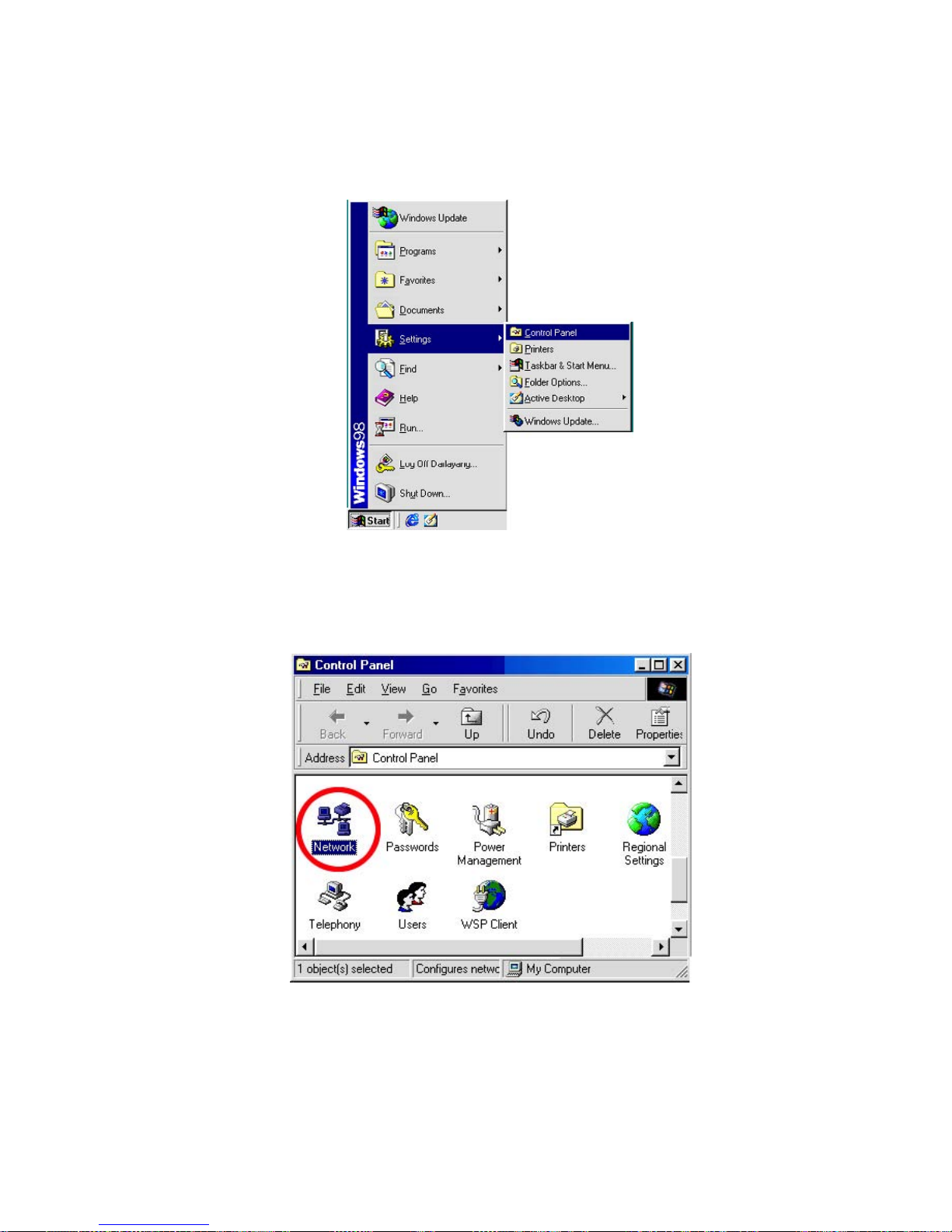
5.3 TCP/IP Communication Software
Follow the instructions below to install the TCP/IP communication program into your computer.
Click the
Start menu from your computer, and point to the Settings/Control panel.
Double click the
Network icon to enter the windows.
18
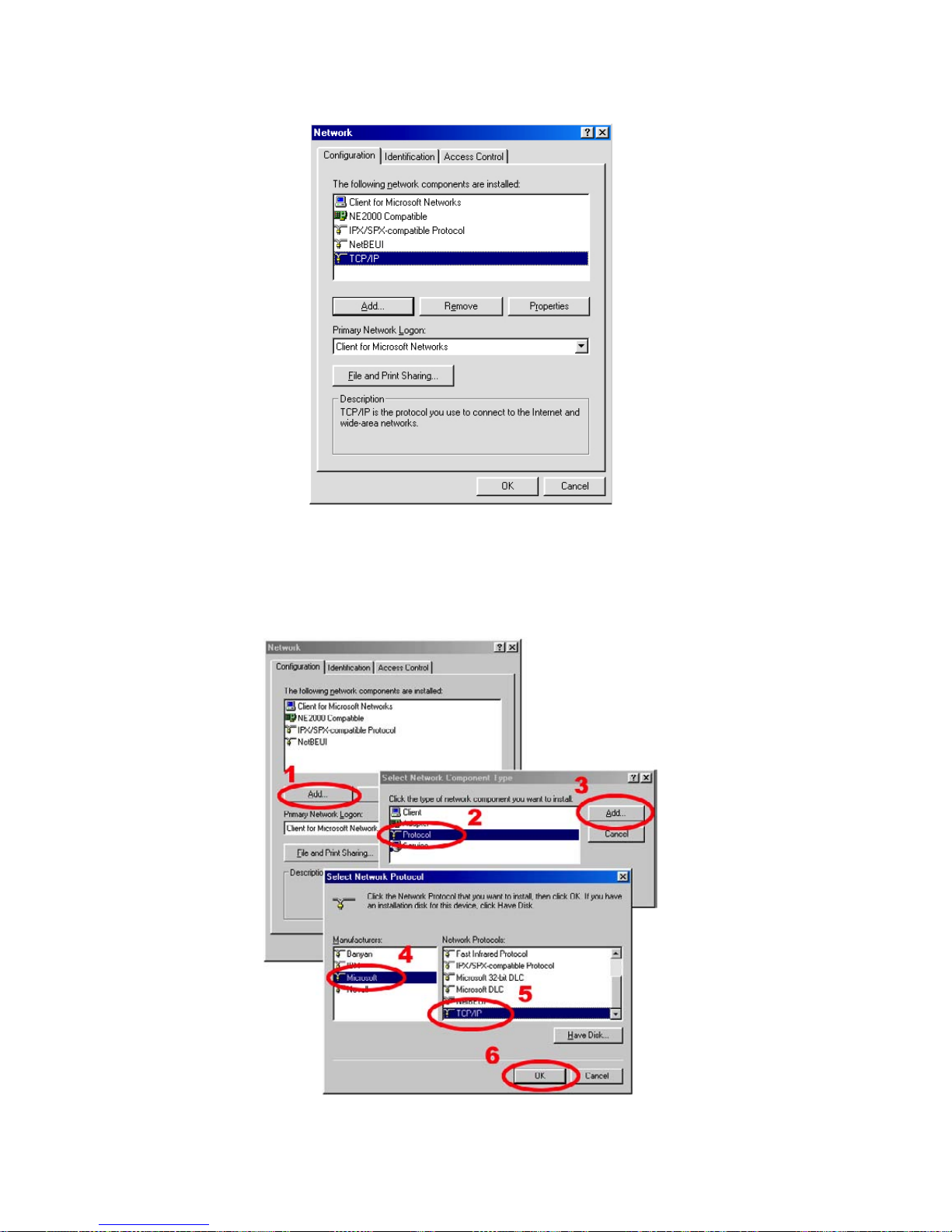
Click the Configuration tag, and check if the TCP/IP is included among the network components list. If the TCP/IP is
included, please process section 5.5. If it is not included, please follow section 5.4 to install the TCP/IP.
During the installation, you will be requested to insert the Windows CD-ROM. After installation, the PC may be restarted.
5.4 TCP/IP Installation
19
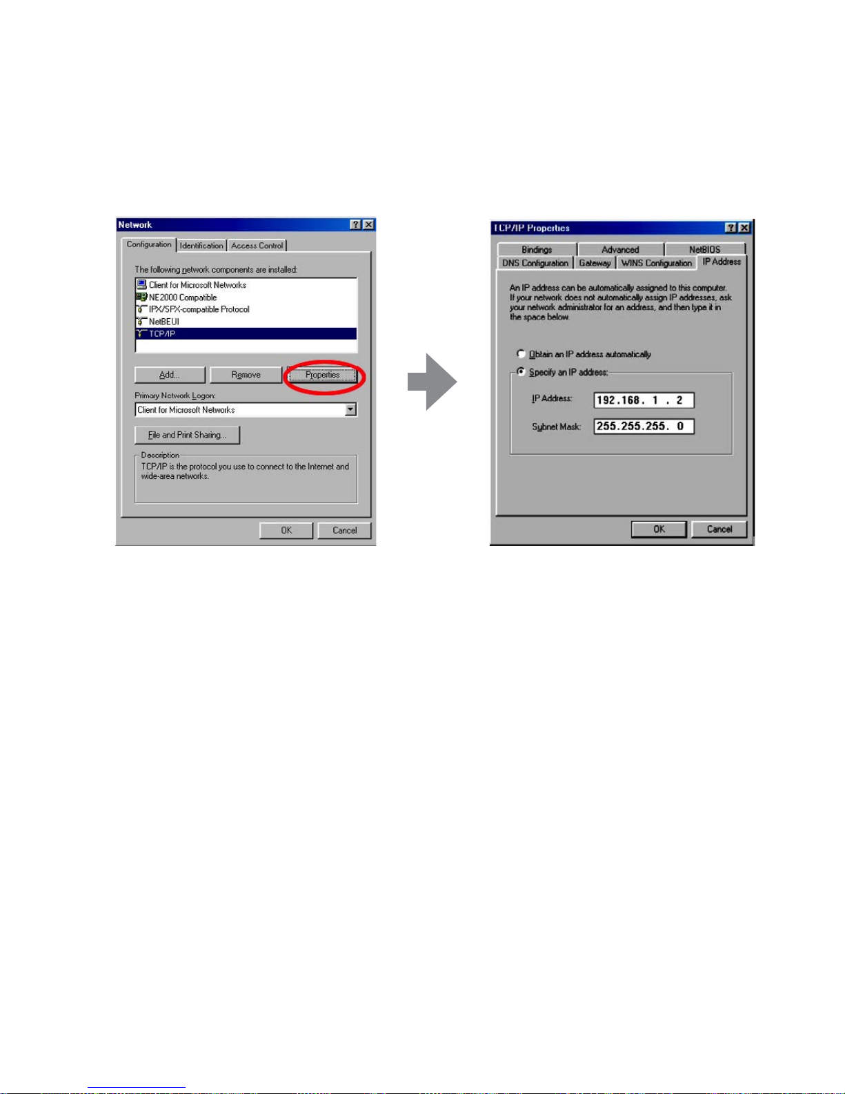
5.5 TCP/IP Configuration Setting
Click Start –> Settings –> Control Panel –> Network
Select
TCP/IP, and then click Properties.
Before processing the IP camera installation in a WAN, please make sure the Internet connection works properly.
If not, please contact your ISP provider.
If you are using a DHCP server, please select
Obtain an IP address automatically. Any assigned IP address for the
connected LAN CAMERAs must be in the same class type as the server. If there is no DHCP server, please select
specify an IP address and type in the IP address of your PC.
NOTE: The IP address of a IP camera in a network must be unique to itself as opposed to those of the
other chosen PCs, but in the same class type.
20
5.6 Connection Testing
With the previous settings, follow the instructions below to ensure whether you have established the connection
successfully.
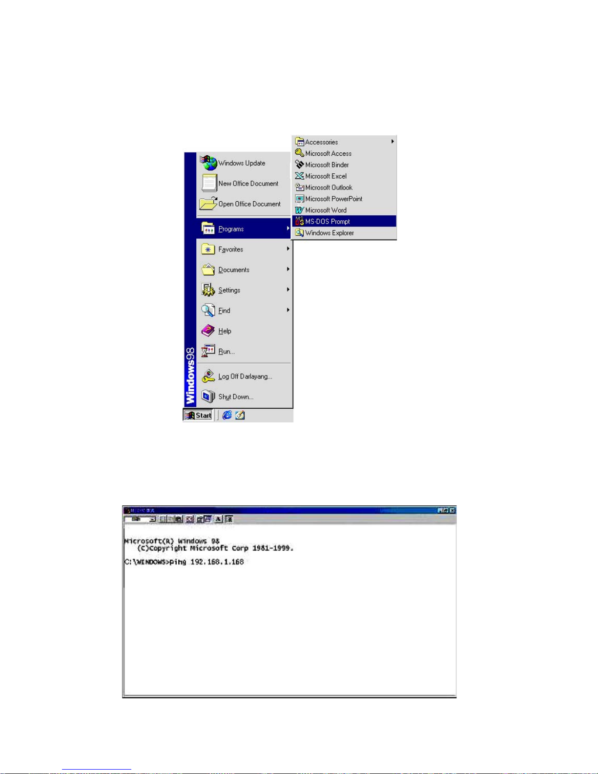
Click
Start –> Programs –> MS-DOS Prompt
Type in
ping 192.168.1.168 then Enter. (See the sample screen below)
• This IP is the IP camera IP address that is assigned for the connected IP camera in step 2.
21
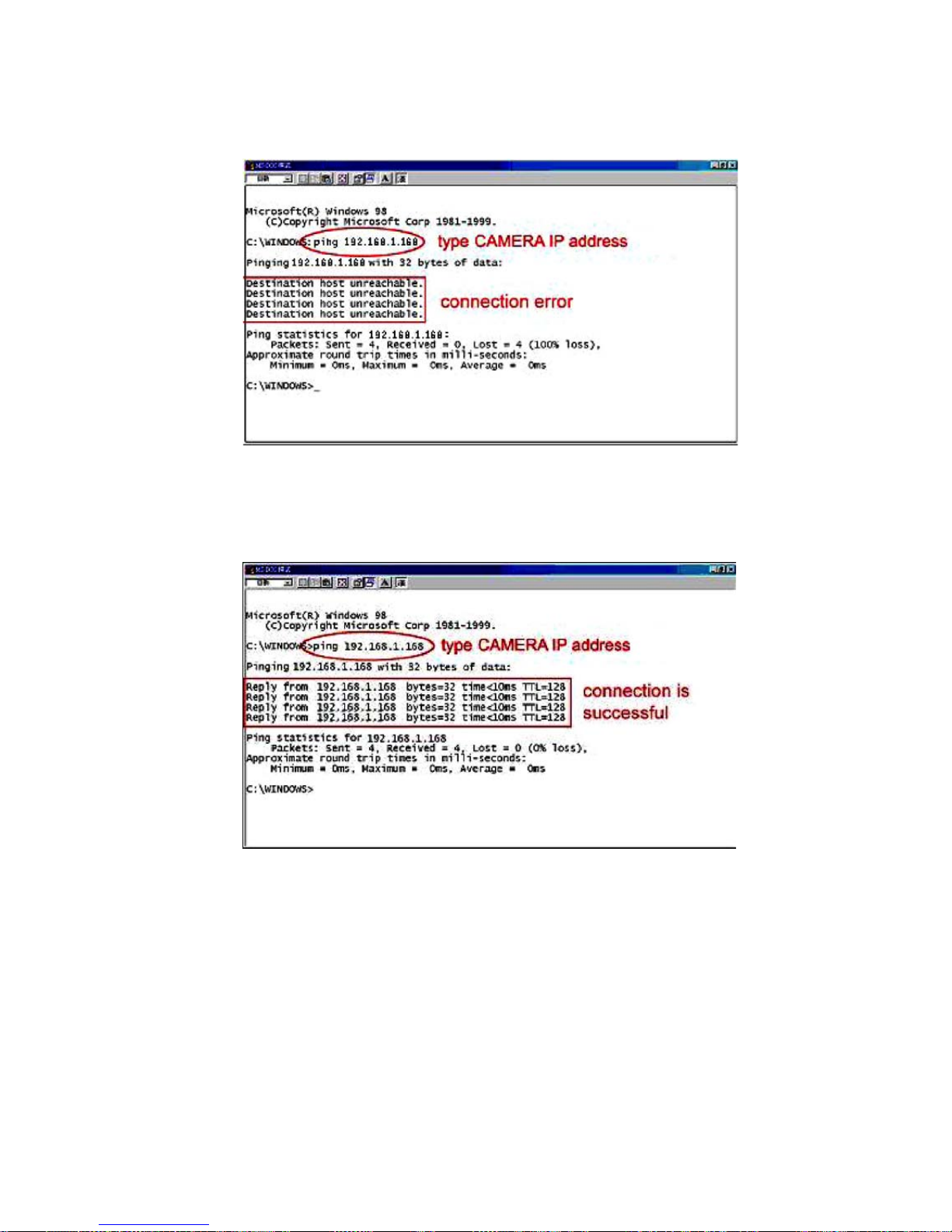
If you receive a response as in the sample screen below, you have successfully made the connection.
If you receive a response as in the sample screen below, the connection hasn’t been successfully established. Please
re-check all the hardware and software installation by repeating steps 1 to 5. If you still can’t establish the connection
after re-checking, please contact your dealer.
22
6. Operating Instructions for Image Software and Network
Two choices of software are available for linking up with the IP camera: (1) the Microsoft Internet Explorer; and (2) the
IP camera VIEWER, a network browser in a PC which provides the functions of monitoring remote zones or watching
recorded data through the TCP/IP protocol.
The details are listed as follows.
System Requirements
• Compatible with operating systems such as Windows 2000 and Windows XP.
• Internet Explorer 6.x.
• Non-network modem installation needs Windows PC.
Wire Type Cat. 5
Connector Type
RJ-45
Max. Cable Length
100m
Hub Wiring Configuration
Straight Through or Cross Over
PC Wiring Configuration
Straight Through or Cross Over
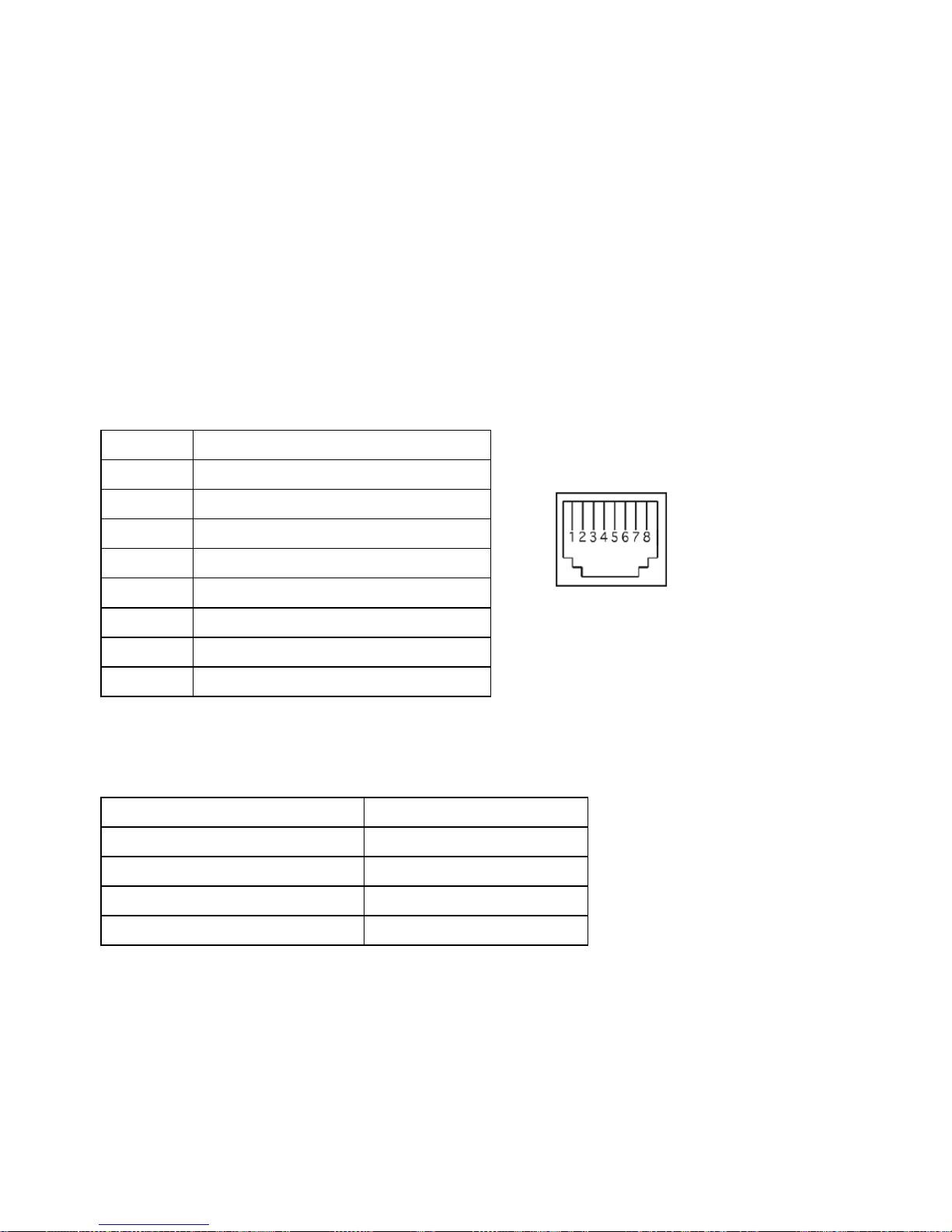
RJ-45 PIN configuration for Ethernet
Physical specification for Ethernet
PIN NO. PIN Assignment
1.
TX +
2.
TX -
3.
RX +
4.
Not Connected
5.
Not Connected
6.
RX -
7.
Not Connected
8.
Not Connected
RJ-45 socket
23
6.1 Microsoft Internet Explorer
6.1.1 Connecting the IP camera
1. Start up the Microsoft Internet Explorer, and then follow the steps below to connect the IP camera.
2. Click the URL block at the top of the window.
3. Enter the URL address of the IP camera into the URL block and press the
„Enter” button to enter the home page.
4. Scroll to the bottom of the page, with its five icons, „Image”, „Network”, „System”, „Application” and „SD Card”.
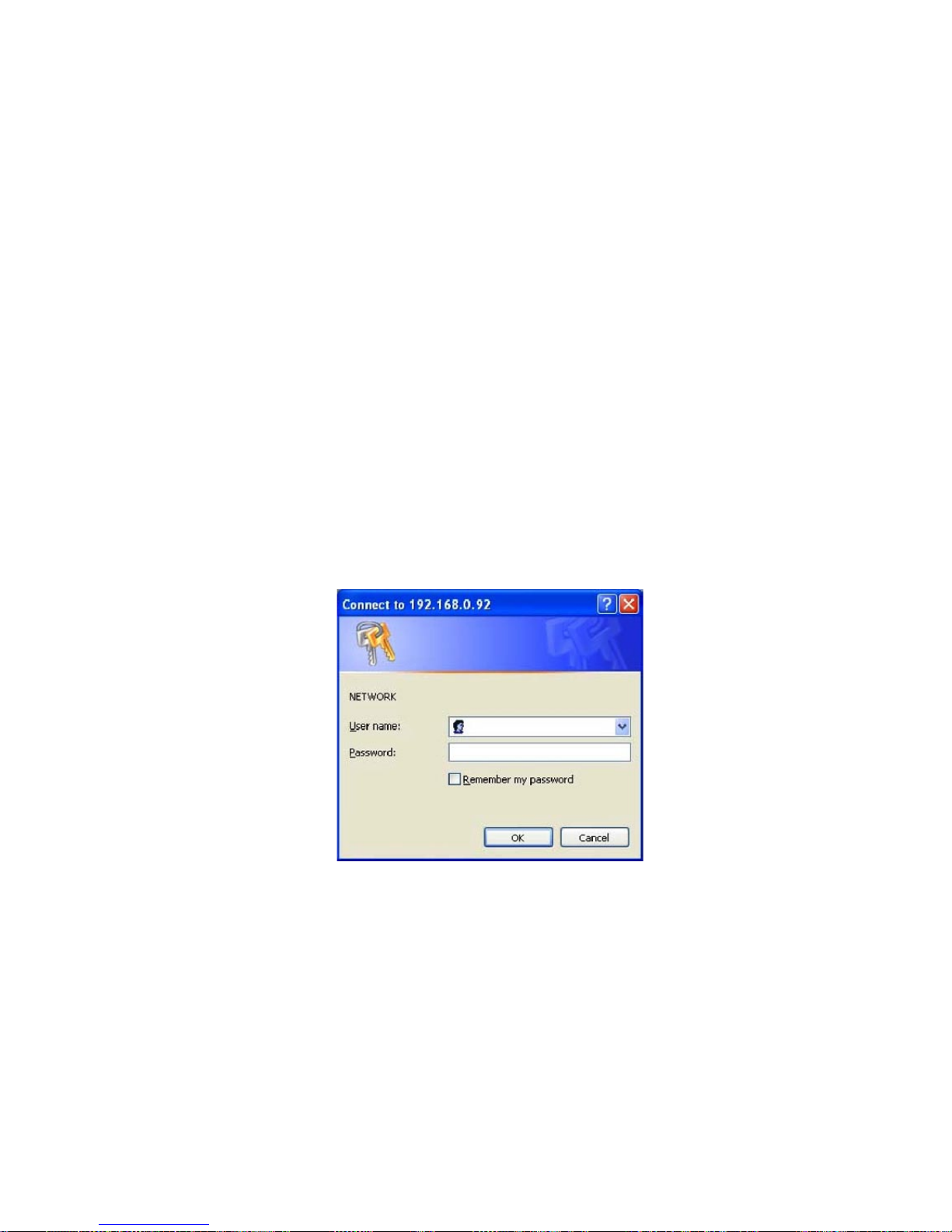
Whichever you click, the page headlined „Enter Network Password” will appear.
5. Type in the „User Name” and „Password” in the appropriate spaces.
6. Click the
„OK” button to set your entries, and automatically exit the page.
NOTE: The default „User Name” and „Password” are admin and 9999 respectively.
NOTE: The page headlined „Enter Network Password” is shown below. Please enter the user name and
password of the IP camera when you see it. If either the user name or the password is incorrect,
please check the input data and rectify it if and as necessary.
NOTE: Once completed and passed, it will not appear again until you close the window and reconnect it.
NOTE: The initial sequence of proceeding is to type in your IP address and click the „Enter” button to access
the home page. If and when you revise or change data in the „SYSTEM USERS” page, the sequence will
alter to initially show the „Enter Network Password” page.
24
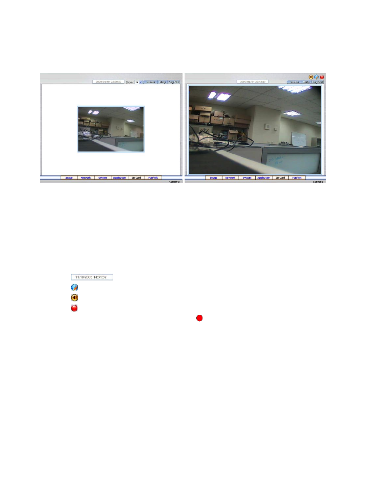
Browsing images from the IP camera
The images from the IP camera will be displayed on the home page while going online with the IP camera. Some
buttons provided at the bottom of the home page for further setting. In MJPEG mode or in MPEG4 mode, there are
different display formats of its home page.
• Click the Image button to enter the image-setting page.
• Click the
Network button to enter the network-setting page.
• Click the
System button to enter the system-setting page.
• Click the
Application button to enter the application-setting page.
• Click the
SD Card button to open the SD Card- FILELIST of the MEMORY CARD window, if the SD card is inserted.
• Click the
Pan/Tilt button to change the Pan/Tilt/Zoom settings.
• Click the
button to change the time/date display mode.
• Click the
button to switch high/low speed network.
• Click the
button to play the live audio. Click once again to deactivate.
• Click the
button to archive AVI videos into your PC. Click once again to deactivate.
In the recording mode, there will appear a red twinkling icon
in the upper-right hand corner of the image.
The AVI file will be saved in the path of c:\.
• Digital zoom function: Click the left mouse button on the video display area, and it will show the zoom-in images.
Double click the left mouse button to see the maximum size. Click the right mouse button on the video display
area, and it will show the zoom-out images. Double click the right mouse button to come back to the normal size.
Homepage of MJPEG mode
Homepage of MPEG4 mode
25
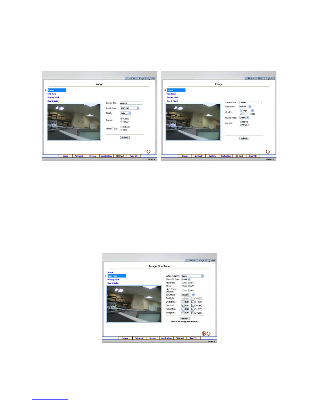
6.1.2 Change Image Setting
Please follow the steps below to change the image setting through the network if and as necessary.
1. Click the
image button on the home page to enter the image-setting page.
Image setting page of MJPEG mode
Image setting page of MPEG4 mode
2. Adjust the image setting including „Device Title”, „Resolution”, „Quality”, „Frame rate” (MPEG4 mode only),
„Format”, and „Viewer Type” (MJPEG mode only) if necessary.
3. Click the
Submit button to submit the new image setting.
4. Click the
Fine Tune button to enter the Image Fine Tune page to set the details of the device including:
„Brightness”, „Saturation” and „Sense Up”. Click the Default button to reset all the settings.
NOTE: The revised image will appear immediately after any change in made.
26
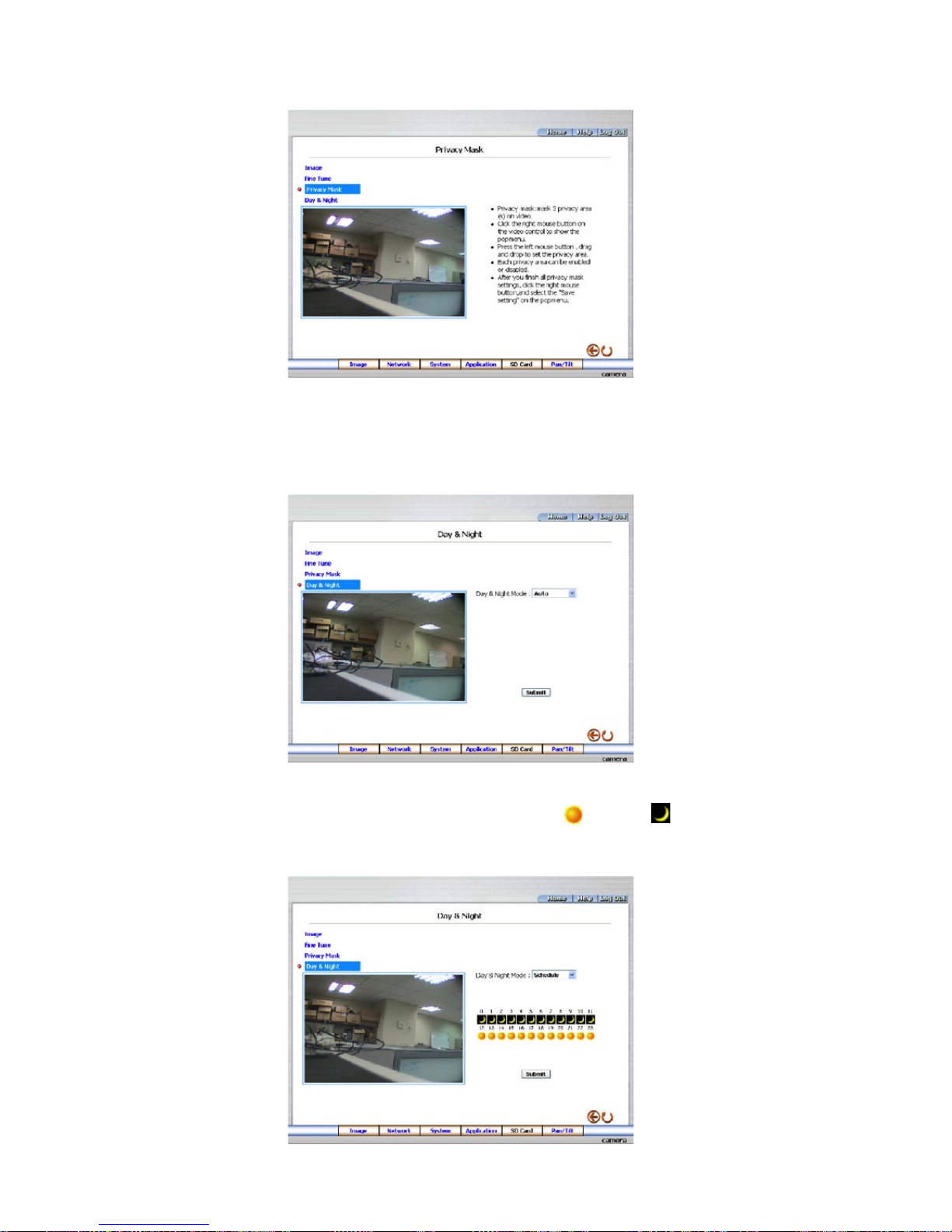
5. Click the Privacy Mask button to enter the Privacy Mask page.
6. Click the Day & Night button to enter the Privacy Mask page. Click the drop-down list to choose the Day & Night
mode of „Auto”, ”Day mode”, „Night mode” and „Schedule”.
NOTE: In the „Schedule” mode, you can click the icon to set the Day
or Night mode of each hour.
„0” means „00:00~00:59”, „1” means „01:00~01:59”, and so on.

27
7. Click the Home button to return to the home page while the new image setting acts on the images to effect the
desired changes instantly. (If the setting has not been changed by the above steps, any (re)entry onto the home
page will find images in their earlier or original setting.)
Exchange the image format
1. Tick on one of the formats then press the
Submit button.
2. The IP camera will restart automatically after several seconds.
Description of function keys
MPEG4 mode
Device Title: Type in the camera title in the given space.
Resolution: Scroll to choose the image resolution from „VGA” or „QVGA”.
Quality: Scroll to choose the image quality out of a spectrum of qualities ranging from „highest”, „high”,
„medium”, and „low” to „lowest”. In MPEG4 mode, you can also set the quality by typing in the value.
The custom quality value must be in the range between 64 Kbps to 8192 Kbps.
Frame rate: Click the drop-down list to choose the frame rates of „15FPS”, „24FPS” or „25FPS”.
Format: Click to choose the „MJPEG” or the „MPEG4” mode.
Fine Tune mode
Brightness: Enter your desired quality of image brightness from a spectrum of 0 to 255.
Saturation: Type in the saturation level in the blank (0 to 255).
MJPEG mode
Viewer type: Click to choose the viewer type of the „ActiveX” or „JAVA Applet” mode.
Submit: Click to submit the new image setting to the IP camera.
Default: Click this button to install the default settings in all the entries for image parameters on this page.
28
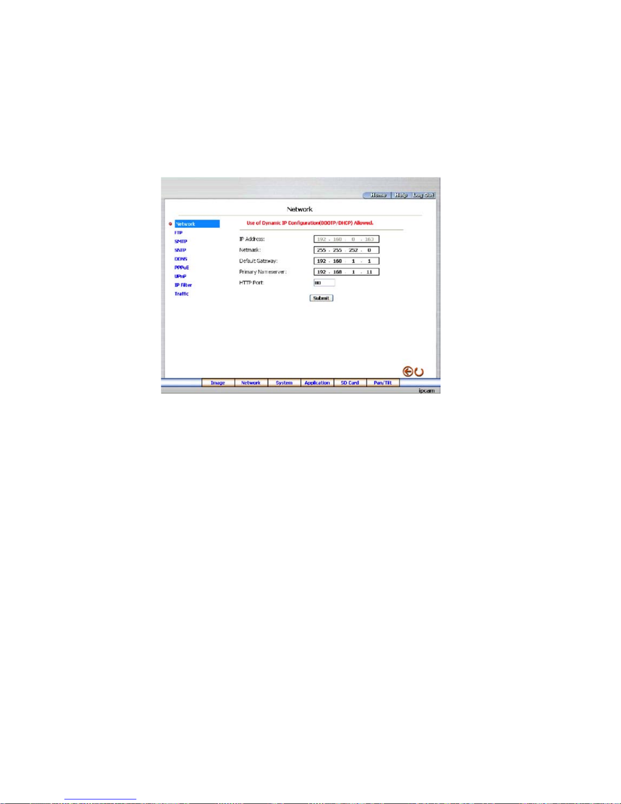
6.1.3 Change the Network Setting
Please follow the steps below to change the network setting through the network if and as necessary.
• Set the network options and IP address
1. Click the network button in the home page to enter the network-setting page.
2. The accessible networks here are the „FTP”, „SMTP”, „SNTP”, „DDNS”, „PPPoE”, „UPnP”, „IP Filter” and the
„Traffic”.
3. Fill in the „IP Address”, „Netmask”, „Default gateway”, „Primary nameserver”, and „HTTP Port Number” if
necessary.
4. Click the
Submit button to submit the new network setting.
5. Click the
Home button to return to the home page.
Description of function keys
IP Address: Enter the 4Byte IP Address in the appropriate blank space (the value in each box may be anywhere
between 0 and 255). Every IP camera has to own an IP address to be identified on the network.
Netmask: Fill in the 4Byte Subnet Mask in the required blank spaces (usually any numbers between 0 and 255).
It is used to identify the subnet where the IP camera is sited.
Default gateway: Type in the 4Byte Gateway in the relevant blank spaces (each unit value must be between 0
and 255).
Primary nameserver: Enter the 4Byte DNS Server Address in the blank spaces provided (each value unit must be
between 0 and 255). The DNS Server is in charge of translating the Domain Name into the IP Address.
HTTP Port Number: Indicates the specific HTTP Port Number. The default is 80.
Submit: Click to submit the new network setting to the IP camera.
29
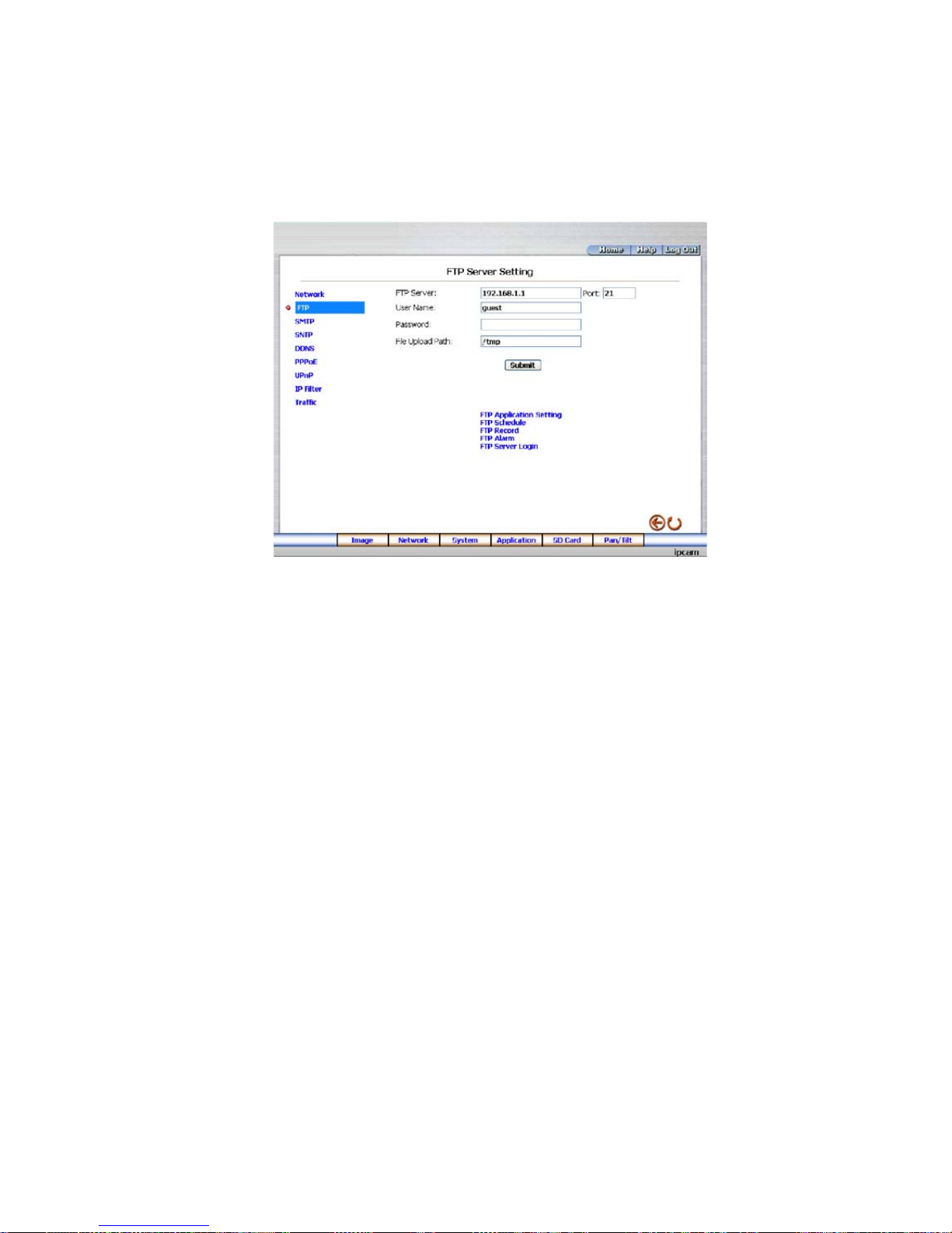
• Change the Network Setting - FTP (MJPEG mode only)
Please follow the steps below to change the FTP setting via the network if necessary to upload recording data live.
1. Click the
FTP button at top left to enter the „FTP Server Setting” page.
2. Type in the „FTP Server” address, the „User Name”, and the „Password” of the FTP Server; and set the
„File Upload Path” of the image files when necessary.
3. Click the
Submit button to submit the new FTP setting of the recording.
4. Click the
Home button to return to the home page.
Description of function keys
FTP IP Address: Enter the FTP server DOMAIN NAME or IP address in the appropriate blank spaces.
User Name: Fill in the FTP user name in the attached blank space (if the data is not provided, warning messages will
show up).
Password: Type in the FTP password in the attached blank space (if the space is blank, warning messages will
show up).
File Upload Path: Enter the upload path while doing the FTP.
Submit: Click to submit the new FTP setting to the network camera.
30
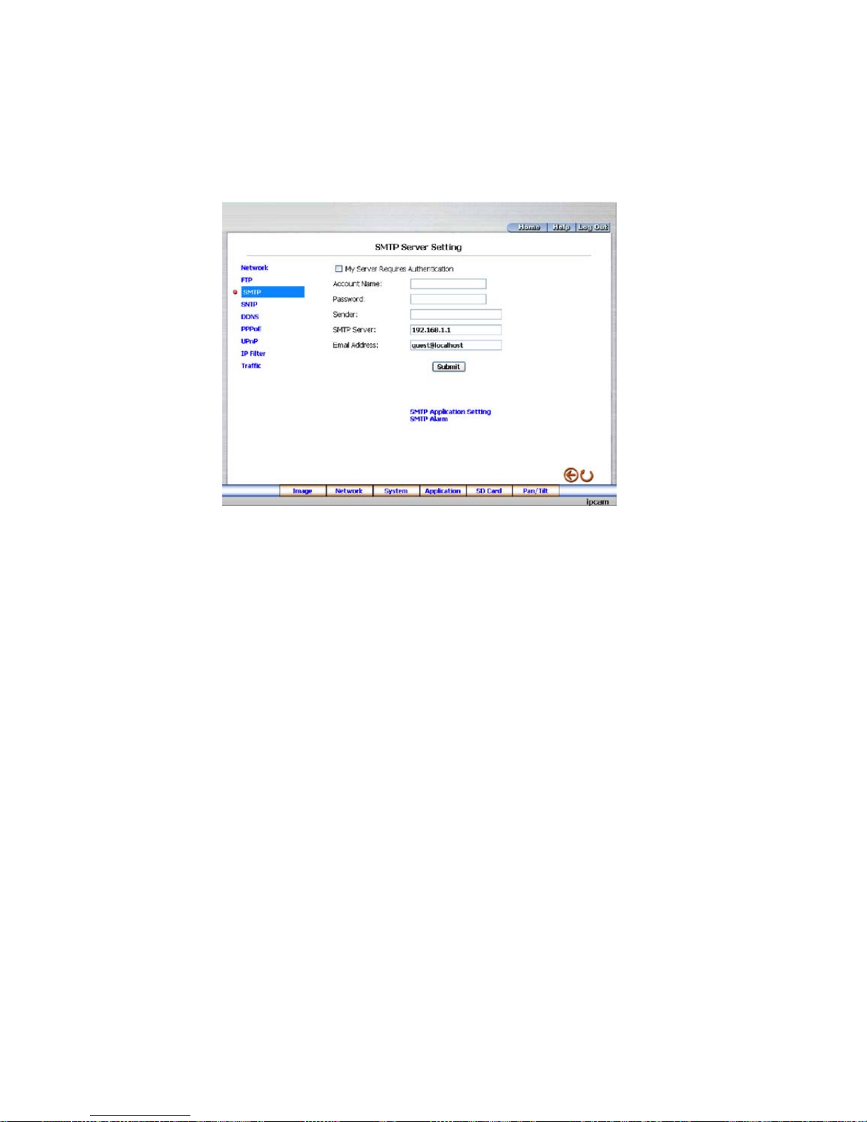
• Change the Network Setting - SMTP (MJPEG mode only)
Please follow the steps below to change the SMTP setting through the network if necessary.
1. Click the
SMTP button at upper left above to enter the „SMTP Server Setting” page.
2. Click ”My Server Requires Authentication” to checkmark the attached box and activate the function.
3. Fill in the Sender name, DOMAIN NAME of the SMTP server, and set the recipient’s e-mail address if necessary.
4. Click the
Submit button to submit the new SMTP setting.
5. Click the
Home button to return to the home page.
Description of function keys
Account Name & Password: Fill in the account name and password if you check marked the „My Server Requires
Authentication” function
SMTP Server: Enter the SMTP server DOMAIN NAME or IP address in the given blank space.
Email Address: The recipient’s e-mail address
Submit: Click to submit the new SMTP setting to the network camera.
 Loading...