

Page 1
TI00123R/09/EN/17.18
71416618
Products Solutions Services
Technical information
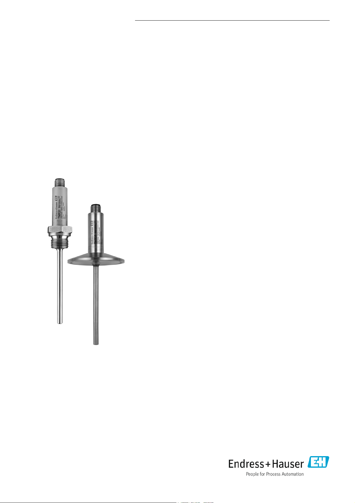
Easytemp TMR31, TMR35
Compact thermometer, Pt100, Class A
Optionally with integrated 4 to 20 mA
transmitter, programmable via PC
Application
The Easytemp TMR31 and TMR35 compact thermometers are used to measure
temperatures from -50 °C to 150 °C (-58 °F to 302 °F), or up to 200 °C (392 °F) with
neck. The most common installation locations are tanks and pipes.
• TMR31 with process connections for general applications.
• TMR35 with process connections for hygienic applications.
Benefits at a glance
Quick installation and easy commissioning:
• Small, compact design made entirely of stainless steel
• M12 connector with IP69K for an easy electrical connection
• 4-wire, Pt100 or PC-programmable transmitter with 4 to 20 mA output
• Configuration and visualization with ReadWin 2000 PC operating software,
which is free of charge
• Preset measuring range is available for order
• Variable insertion lengths from 40 mm to 600 mm (1.6 to 23.6 in)
Outstanding metrological properties thanks to innovative sensor technology:
• Extremely short response times
• Highly accurate even with short insertion lengths
• Thin film sensor element Pt100, accuracy class A (IEC 60751)
Safe operation with approvals and certificates:
• UL recognized component
• Meets all EMC requirements according to NAMUR NE21
• Breakdown information in event of sensor break or sensor short-circuit, adjustable
as per NAMUR NE43
• TMR35: Hygienic compatible design with 3-A marking and EHEDG certification
• Marine approval
Page 2
TMR31, TMR35
HAW562
3 OUT 4
1 IN 2
HAW562
3 OUT 4
1 IN 2
Ecograph T
RN221 N
HAW562
HAW562
TMR31
ENDRESS+HAUSER
RN 221 N
ENDRESS+HAUSER
RN 221 N
Function and system design
Measuring principle Electronic recording and conversion of Pt100 input signals in industrial temperature measurement.
Measuring system The compact thermometer uses a Pt100 (Class A) sensor element for measurement. The device is
available with a Pt100 4-wire connection or, optionally, with an analog, temperature-linear 4 to 20
mA output signal. A built-in transmitter in the device converts the Pt100 input signal into the 4 to 20
mA signal and can be programmed using a PC via the M12 connector. The compact thermometer has
different process connections for general (TMR31) and hygienic applications (TMR35).
The Easytemp TMR31, TMR35 has a new kind of thin film sensor element that is soldered directly into
the sensor tip. This innovative sensor design ensures ideal heat transfer from the process to the sensor
element. This means that extremely fast response times and high levels of accuracy can be achieved
even with short insertion lengths.
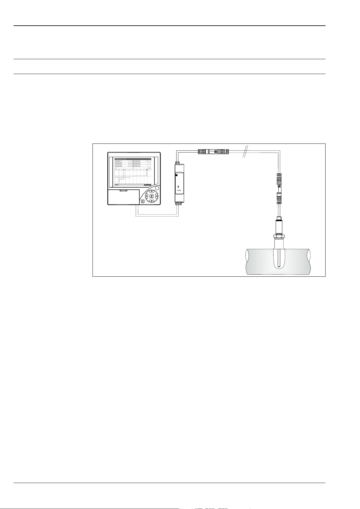
Measuring point layout (example) for Easytemp compact thermometer TMR31 with additional Endress+Hauser components
Ecograph T, active barrier RN221 N and HAW562 surge arrester
A0006994
Multi Channel Recorder Ecograph T
Multi-channel recorder Ecograph T in 144 x 144 mm (5.7 x 5.7 in) panel-mounted housing for the
electronic detection, display, recording, analysis, remote transmission and archiving of analog and
digital input signals. Data recording system on CompactFlash card, multi-colored LCD display, 120 mm
(4.72 in) screen size. Configuration and measured value display via interfaces (USB, Ethernet, RS232/
485) and ReadWin 2000 PC operating software.
Active barrier RN221 N
Active barrier with power supply for the safe separation of 4 to 20 mA standard signal circuits with
optional intrinsically safe input. The current applied by the transmitter of the compact thermometer in
the input circuit (4 to 20 mA) is transmitted linearly to the output.
Surge arrester HAW562
Protects consumer installations or measuring devices as well as signal lines and components against
overvoltage which is induced by lightning striking in the distance or through switching operations. The
HAW562 module acts as an overvoltage protection system in terminal block systems to protect signal
lines and components and is installed on a module carrier (HAW560).
2 Endress+Hauser
Page 3
TMR31, TMR35
M12x1
J
Pt100
A
B
1
10...35 VDC
(4-20 mA)
3
0 V
(4-20 mA)
4
2
1 (BN) +
2 (WH) nc
3 (BU) 4 (BK) nc
Input
Measuring principle Temperature (temperature-linear transmission behavior)
Measuring range
Designation Measuring range limits Min. span
Pt100 as per IEC 60751 -50 to 150 °C (-58 to 302 °F) without neck
Output
Output signal • Standard: Pt100, Class A, 4-wire
• Optional: 4 to 20 mA or 20 to 4 mA
Signal on alarm Signal on alarm as per NAMUR NE43
• Underranging: Linear drop to 3.8 mA
• Overranging: Linear rise to 20.5 mA
• Sensor break; sensor short-circuit:
3.6 mA or 21.0 mA (at settings 21.0 mA, 21.5 mA output is guaranteed)
Maximum load (U
power supply
Min. current consumption 3.5 mA
Current limit 23 mA
Switch-on delay 2 s
- 10 V) / 0.023 A (current output)
-50 to 200 °C (-58 to 392 °F) with neck
10 K (18 °F)
Power supply
Electrical connection cables must comply with 3-A sanitary standard, must be smooth, corrosion
resistant and cleanable.
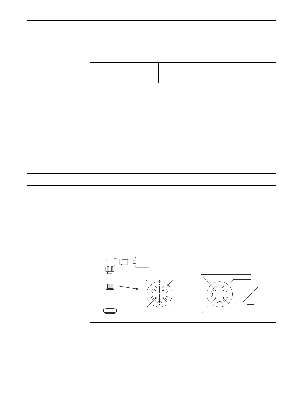
Electrical connection
A: with electronics, M12 plug, 4-pin
Pin 1: power supply 10 to 35 V DC; current output 4 to 20 mA (cable connection, wire color brown = BN)
Supply voltage Ub= 10 to 35 V DC
Pin 2: connection of PC configuration cable - shortened pin (cable connection, wire color white = WH)
Pin 3: power supply 0 V DC; current output 4 to 20 mA (cable connection, wire color blue = BU)
Pin 4: connection of PC configuration cable - shortened pin (cable connection, wire color black = BK)
B: without electronics, Pt100, 4-wire connection
A0020176
Endress+Hauser 3
Page 4

TMR31, TMR35
Residual ripple Permitted residual ripple Uss 3 V at Ub 13 V, f
Performance characteristics
Response time 3 s with transmitter
Reference operating conditions
Maximum measured error Electronics
• Matching temperature (ice bath) 0 °C (32 °F) for Pt100 sensor
• Ambient temperature 25 °C ± 5 °C (77 °F ± 9 °F) for transmitter
0.1 K (0.18 °F) or 0.08%. % relates to the set span. The larger value applies.
Sensor (Pt100) for version without transmitter
• Tolerance class A as per IEC 60751, operating temperature range -50 to 200 °C (-58 to 392 °F) with
neck
• Maximum measured error in °C = 0.15 + 0.002 T
T = Numerical value of the temperature in °C without regard to the leading sign.
Total deviation of electronics + sensor
• Operating temperature range:
-50 to 150 °C (-58 to 302 °F) without neck
-50 to 200 °C (-58 to 392 °F) with neck
• 0.25 K + 0.002 T
max.
= 1 kHz
Long-term stability of electronics
Influence of ambient temperature (temperature drift)
0.1 K (0.18 °F)/year or 0.05%/year
Data under reference conditions. % relates to the set span. The larger value applies.
• Pt100 resistance thermometer:
= ±(15 ppm/K * (full scale value of measuring range + 200) + 50 ppm/K * set measuring range)
T
d
* T
T= deviation of ambient temperature from the reference operating condition.
Influence of load ± 0.02%/100
Specifications refer to the full scale value of the measuring range.
Transmitter response time 1 s
Sensor response time Measured as per IEC 60751, in water flowing at 0.4 m/s (1.3 ft/s)
t
50
< 1.0 s < 2.0 s
t
90
Influence of supply voltage ± 0.01%/V deviation from 24 V
Specifications in percent refer to the full scale value of the measuring range.
Self-heating Negligible small
Sensor current 0.6 mA
4 Endress+Hauser
Page 5
TMR31, TMR35
AB
C
L
L
³ 3°
C
12
3
4
R0.4 R0.4
Sensor with
milk pipe
connection
Sensor with Varivent
connection
Shaped
gasket
Companion
connection
O-ring
Groove
slip-on nut
Centering ring
Sealing
Companion
connection
Companion
connection
Gasket
(O-ring)
Welding boss
Leak detection hole
Vessel wall
Installation conditions
Orientation No restrictions. However, self-draining in the process must be guaranteed. If there is an opening to
detect leaks at the process connection, this opening must be at the lowest possible point.
Installation instructions Mounting location
The insertion length of the compact thermometer can have a substantial influence on the accuracy. If
the insertion length is insufficient, heat dissipation via the process connection and the container wall
can cause measurement errors. To minimize errors caused by heat dissipation, a minimum insertion
length of L
= 40 mm (1.6 in) is recommended.
min
A0020345
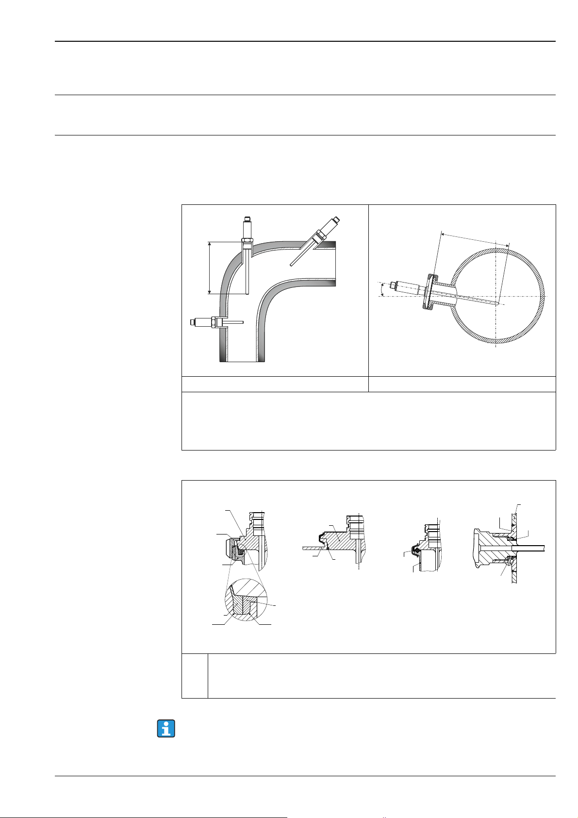
TMR31 - general applications TMR35 - hygienic applications
Pipe installation of the compact thermometer:
• A: On angle brackets
• B: In smaller pipes, inclined
• C: Perpendicular to the direction of flow, TMR35 with minimal 3° inclination because of self draining
• L = Insertion length
Mounting instructions for installation in various hygienic processes
Milk pipe connection as per DIN 11851 only in connection EHEDG certified and self centering ring
1
to EHEDG position paper
2
Clamp as per ISO 2852, only in connection with seal according to EHEDG position paper
3
Liquiphant-M G1" process connection, horizontal installation
4
The matches for the process connections as well as the gaskets are not included in the scope of delivery
of this assembly. Welding adapter for process connections with associated O-ring sets are available as
accessories, 14.
Endress+Hauser 5
A0012591
A0011758-EN
Page 6

Procedure in case of seal failure indicated by leak detection port:
• Disassembling of the thermometer, validated cleaning procedure of thread and sealing ring groove
• Replacement of the seal or sealing ring
• CIP after re-assembly
In the case of weld-in connections, exercise the necessary degree of care when performing the welding
work on the process side:
• Suitable weld material.
• Flush welding or with welding radius > 3.2 mm.
• Absence of pits, folds, crevices.
• Ground and polished surface (R
As a general rule, the thermometers should be installed in such a way that does not adversely affect
their cleanability (3-A requirements must be adhered to). The required flush-mounting can be
achieved by the connection Varivent®, Liquiphant (+ weld-in adapter).
Environment conditions
Ambient temperature limits -40 to +85 °C (-40 to 185 °F)
0.76 μm).
a
TMR31, TMR35
Storage temperature -40 to +85 °C (-40 to 185 °F)
Altitude
Up to 2000 m (6600 ft) above mean sea level
Climate class As per IEC 60654-1, Class C
Degree of protection IP66/67 with coupling and connecting cable (not evaluated by UL) 14
IP69K with cordset (not evaluated by UL) 14
Shock resistance 4g / 2 to 150 Hz as per DIN EN60068-2-6
Vibration resistance Refer to ’Shock resistance’
Electromagnetic compatibility (EMC)
EMC to all relevant requirements of the IEC/EN 61326- series and NAMUR NE21. For details see
declaration of conformity.
ESD (Electrostatic discharge) IEC/EN 61000-4-2 6 kV cont., 8 kV air
Electromagnetic fields IEC/EN 61000-4-3 0.08 to 2 GHz 10 V/m
Burst (fast transient) IEC/EN 61000-4-4 2 kV
Surge IEC/EN 61000-4-5 0.5 kV sym.
Conducted RF IEC/EN 61000-4-6 0.01 to 80 MHz 10 V
All EMC measurements were performed with a turn down (TD) = 2:1. Maximum fluctuations during
EMC- tests: < 1 % of measuring span.
Interference immunity to IEC/EN 61326 - series, requirements for industrial areas
Interference emission to IEC/EN 61326 - series, electrical equipment Class B.
Condensation Permitted
Electrical safety • Protection class III
• Overvoltage category II
• Pollution degree 2 III
6 Endress+Hauser
Page 7
TMR31, TMR35
0
20
40
60
80
100
0 30 60 90 120 150 180 210 240 270 300
L (mm)
P (bar)
0
300
600
900
1200
1500
P (psi)
01234 5 78910
11
L (in)
6
12
Process conditions
Process temperature limits The electronics of the TMR31 and TMR35 must be protected from temperatures above 85 °C (185 °F)
by a neck of appropriate length. TMR31 and TMR35 compact thermometers without electronics
(Pt100, 4-wire) do not require a neck.
• -50 to 150 °C (-58 to 302 °F) without neck
• -50 to 200 °C (-58 to 392 °F) with neck
• -50 to 200 °C (-58 to 392 °F) without electronics
Restrictions depending on process connection and ambient temperature:
• For installation with adjustable insertion length (welding boss with sealing taper, Order No.
51004751; collar welding boss Order No. 51004752; compression fitting with sealing taper,
Order No. 51004753) provide a neck with an appropriate length.
• For TMR31 with process connection:
Max. ambient temperature Max. process temperature
Without neck With neck 35 mm (1.38 in)
Up to 25 °C (77 °F) 150 °C (302 °F) 200 °C (392 °F)
Up to 40 °C (104 °F) 135 °C (275 °F) 180 °C (356 °F)
Up to 60 °C (140 °F) 120 °C (248 °F) 160 °C (320 °F)
Up to 85 °C (185 °F) 100 °C (212 °F) 133 °C (271 °F)
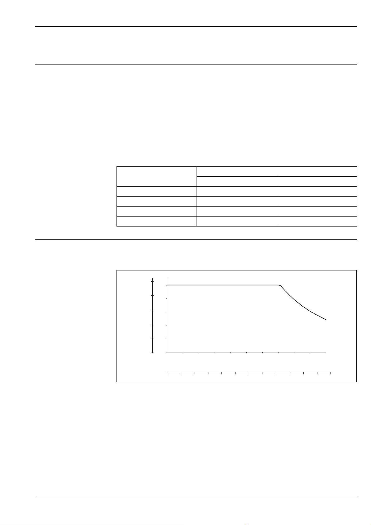
Process pressure limits Maximum permitted process pressure depending on the insertion length. It is limited further by the
process connection in question. Follow the designs of process connection in section "Mechanical
construction" and section "Accessories".
Maximum permitted process pressure
L Insertion length
p Process pressure
The diagram takes into consideration not only the overpressure but also the pressure load caused by
the flow, whereby a safety factor of 1.9 has been specified for operation with flow. The maximum
permitted static operating pressure is lower at greater insertion lenghts due to the increased bending
load caused by the flow. The calculation assumes the maximum permitted medium velocity for the
respective insertion length (see diagram below).
A0008063
Endress+Hauser 7
Page 8
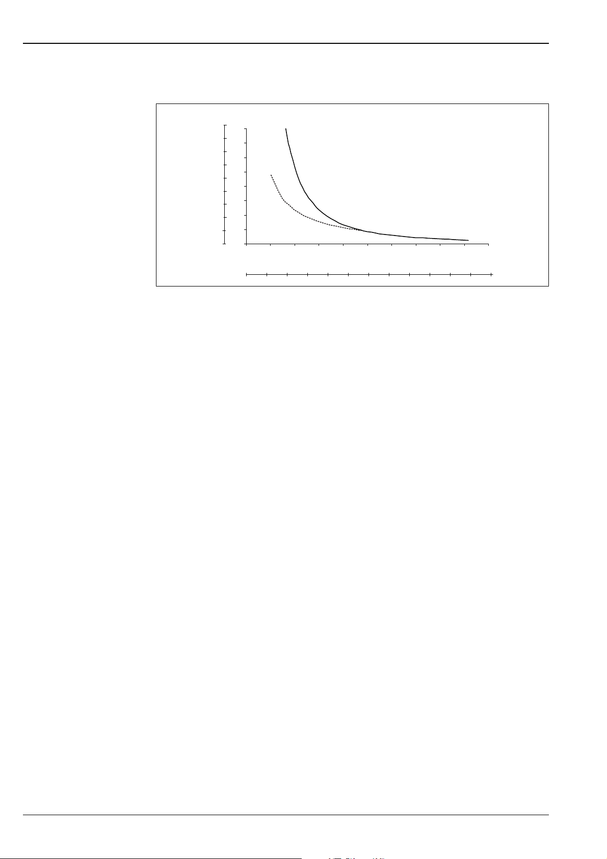
Permitted flow velocity depending on the insertion length
v (ft/s)
01234 5 78910
11
L (in)
6
12
0
5
10
15
20
25
30
35
40
0 30 60 90 120 150 180 210 240 270 300
L (mm)
v (m/s)
0
15
30
45
60
75
90
105
120
B
A
Permitted flow velocity
L Insertion length, during flow
v Flow velocity
A Medium water at T = 50 °C (122 °F)
B Medium superheated steam at T = 200 °C (392 °F)
TMR31, TMR35
A0008065
The permitted flow velocity is the minimum from resonance velocity (resonance distance 80%) and
load or buckling caused by flow, which would lead to failure of the thermometer tube or to exceedance
of the safety factor (1.9). Calculation was performed for the specified limit operating conditions of
200 °C (392 °F) and ≤ 100 bar (1450 psi) process pressure.
8 Endress+Hauser
Page 9
TMR31, TMR35
M12x1 M12x1
M12x1
M12x1
L
1
L
1
L
2
L
1
A
B
C
L
H
M12x1
L
65 (2.56)
65 (2.56)
61 (2.4)
50 (1.97)
71 (2.8)
M12x1
H
41 (1.61)
D
DE
F
D
D
D
D
D
H
H
H
H
H
12 (0.47)
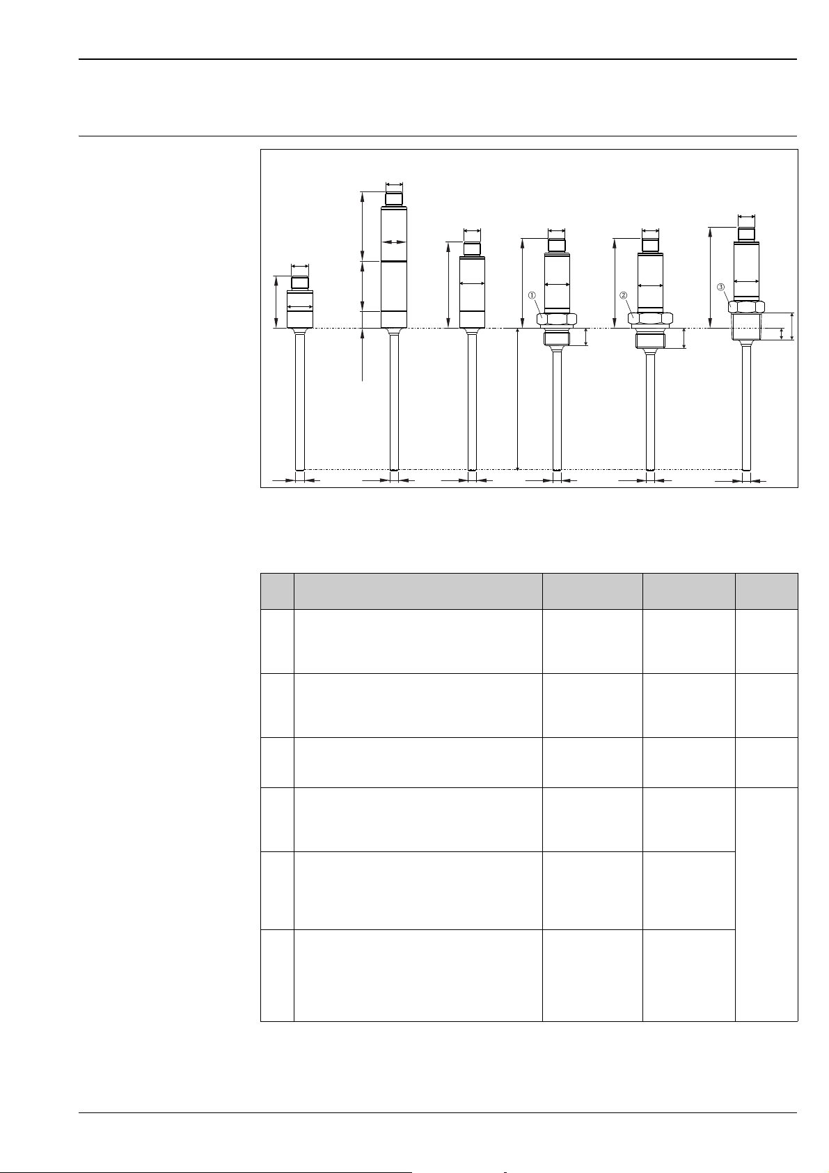
TMR31 design, dimensions
Mechanical construction
A0020192
TMR31 - dimensions in mm (in)
L = Insertion length L variable from 40 to 600 mm (1.6 to 23.6 in)
⌀D = Diameter D = 6 mm (0.25 in)
⌀H = Sleeve diameter 18 mm (0.71 in)
Item
TMR31 version Thread length L1Thread length L2P
No.
A Short sleeve (without built-in transmitter, without
---
max.
neck, without process connection). Refer to chapter
’accessories’ for matching welding bosses and
compression fittings.
BWith neck; L
= neck length 35 mm or 50 mm
--(1.38 in or 1.97 in), without process connection.
Refer to chapter ’accessories’ for matching welding
bosses and compression fittings.
C Without neck, without process connection. Refer to
--chapter ’accessories’ for matching welding bosses
and compression fittings.
D Without neck; Metric thread process connection:
100 bar
(1450 psi),
M14x1.5 ( = AF19)
M18x1.5 ( = AF24)
E Without neck; Inch thread process connection,
cylindrical,
as per ISO 228:
G ¼" ( = AF19)
G ½" ( = AF27)
F Without neck; Inch thread process connection,
conical:
ANSI NPT ¼" ( = AF19)
ANSI NPT ½" ( = AF27)
BSPT R ½" ( = AF22)
12 mm (0.47 in) -
12 mm (0.47 in)
14 mm (0.55 in)--
14.3 mm (0.56 in)
19 mm (0.75 in)
19 mm (0.75 in)
5.8 mm (0.23 in)
8.1 mm (0.32 in)
8.1 mm (0.32 in)
7
Endress+Hauser 9
Page 10
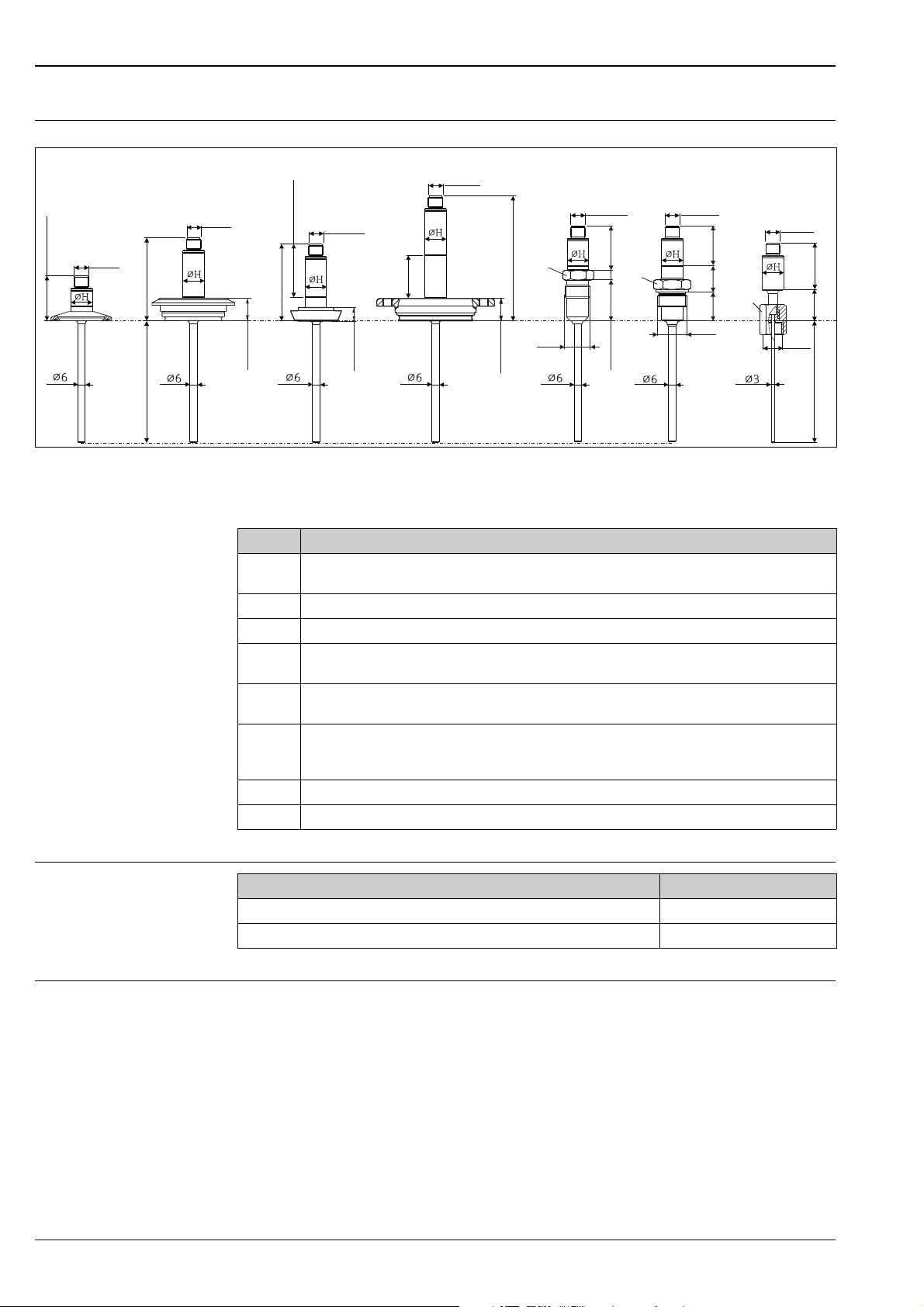
TMR35 design, dimensions
E
L
F
M12x 1
G3/8 ”
SW/A F
19
G
39 (1.54)
83 (3.27)
35
(1.38)
M12x1
115 (4.53)
M12x1
43.4 (1.71)
M12x1
G¾”/
G1”
26.14
(1)
SW/A F
32
D
C
19 (0.75)
35
(1.38)
37 (1.46)
G½”
SW/A F
22
M12x1
18 (0.71)
13 (0.51)
77.9 (3.07)
20.
8
(0.82)
26.
4
(1.04)
8
32.9
(1.3
)
(0.12)
M12x1
72.9 (2.87)
M12x1
48.9 (1.93)
B
A
(0.25)
(0.25)
(0.25)
(0.25)
(0.25)
(0.25)
TMR35 - dimensions in mm (in)
L = Insertion length L variable from 40 to 600 mm (1.6 in to 23.6 in)
⌀H = Sleeve diameter 18 mm (0.71 in)
TMR31, TMR35
A0018283
Weight
Item No. TMR35 version
A Short sleeve (without built-in transmitter, without neck), with 1" process connection (exemplarily for
minimum length)
B Without neck; Process connection Varivent F
C Without neck; Process connection to DIN 11851
D With neck 35 mm (1.38 in), with APV-INLINE process connection (exemplarily for maximum
length)
E Short sleeve (without built-in transmitter, without neck); Conical metal-metal for hygienic processes,
G½" thread. Suitable welding boss available as accessory ( 14).
F Short sleeve (without built-in transmitter, without neck); Process connection for hygienic processes,
G¾" or G1" thread, material SS316L (1.4404). Suitable Liquiphant process fitting available as
accessory ( 14).
G Short sleeve (without built-in transmitter), with neck, Insertion length = 83 mm (3.27 in)
H With neck; Insertion length = 38 mm (1.5 in)
Version with L = 100 mm (3.94 in) Weight
TMR31 with G½", ISO 228 process connection 116 g (4.1 oz)
TMR35 with ISO2852 DN25-38, with clamp process connection (DB) 1 to 1½" 305 g (10.76 oz)
Material • Transmitter housing: SS 304
• Parts in contact with process and process connection: SS 316L, R
TMR35 Ra 0.38 μm (15 μin), electro-polished.
10 Endress+Hauser
0.76 μm (30 μin). Optionally for
a
Page 11
TMR31, TMR35
DBDB DLDL
LLLL
18 (0.71)18
(0.71)
HLHL
B
19 (0.75)19 (0.75)
PLPL
13 (0.51)13 (0.51
)
PHPH
13 (0.51)13 (0.51)
(APV-Inline)(APV-Inline)
(CLAMP 1”)(CLAMP 1”) (CLAMP 2”)(CLAMP 2”)
(Varivent N )(Varivent N )
LBLB
18 (0.71)
(Varivent F)(Varivent F)
(DIN 11851)(DIN 11851)
(DIN 11851)(DIN 11851)
L
13 (0.51)13 (0.5
1)
PGPG
(DIN 11851)(DIN 11851)
10 (0.39)10 (0.39
)
DPDP
(CLAMP 2.5”)(CLAMP 2.5”)
10 (0.39)1
0 (0.39)
G 3/8G 3/8
SW/AF19SW/AF
1
9
35
(1.38)
35
(1.3
8)
G¾”, G1G¾”, G1”
L
1
SW/AF32SW/AF32
37 (1.46)
7 (1.46)
3
G½”G½”
L
1
SW/AF22SW/AF22
R1R1AB / AC / A DAB / AC / A D MBMB
9 (0.35)9
(0.35)
DM (Microclamp)DM (Microclamp)
4.8 (0.18)4.8 (0.
18)
Ø42.9 (1.7)Ø42.9 (1.7)
Ø26 (1.02)Ø26 (1.02)
13 (0.51)1
3 (0.51)
PMMP
(DIN 118
(DIN 11864)64)
26.14 26.14
(1.03) (1.03)
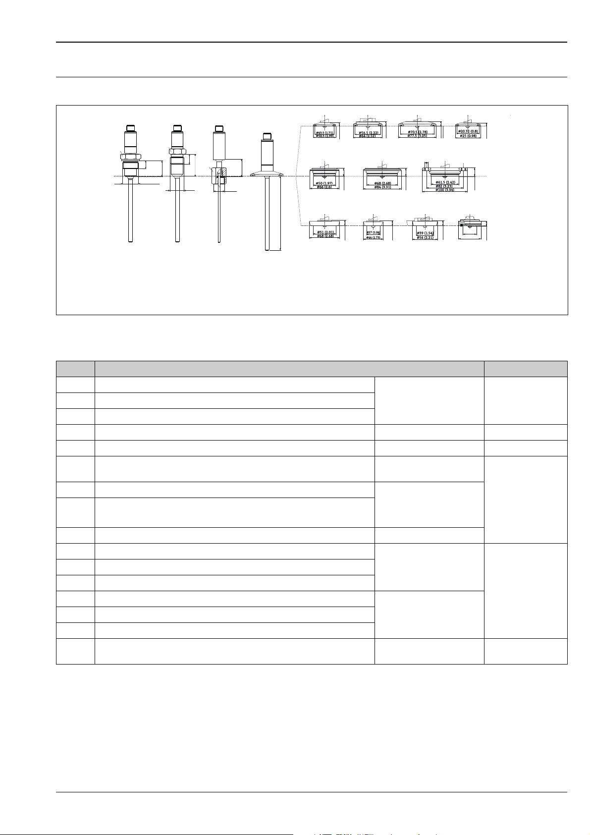
TMR35 design, dimensions for process connections
L = Insertion length L
All dimensions in mm (in).
A0018307
Item No. Process connection versions TMR35 P
AB Weld-in for thread G ¾"/D6, thread length L1 = 16 mm (0.63 in)
AC Weld-in for thread G ¾"/D6, thread length L1 = 16 mm (0.63 in)
3-A marked and
EHEDG certified
max.
See section
’Accessories’, 14
AD Weld-in for thread G 1"/D6, thread length L1 = 18.7 mm (0.78 in)
MB Conical metal to metal, thread G 1/2", thread length L1 = 14 mm (0.55 in) - 16 bar (232 psi)
R1 Spring loaded cap-nut for mounting in thermowell, thread G 3/8" - -
DB Clamp 1"...1½" (ISO 2852) or DN 25...DN 40 (DIN 32676), ASME BPE TypB
3-A marked
compliant
DL Clamp 2" (ISO 2852) or DN 50 (DIN 32676) 3-A marked and EHEDG
DP Clamp 2½" (ISO 2852)
certification (Sealing
according to EHEDG positions
16 bar (232 psi)
paper, DN25, DN40, DN63,5).
DM Microclamp ½"...¾", 316L -
LB Varivent F DN25-32, PN40
LL Varivent N DN40-162, PN40
HL APV inline, DN50, PN40, 316L, (B = 6 x ⌀8.6 (0.34") bores + 2 x M8 thread)
PL DIN 11851, DN50, PN40 (including cap-nut)
PG DIN 11851, DN25, PN40 (including cap-nut)
PH DIN 11851, DN40, PN40 (including cap-nut)
PM DIN 11864, DN25 (including cap-nut) 3-A marked and EHEDG
3-A marked and EHEDG
certified
3-A marked and EHEDG
certification (only with
EHEDG-certified and selfcentering sealing ring).
certification
40 bar (580 psi)
40 bar (580 psi)
Endress+Hauser 11
Page 12
TMR35 design, dimensions
3 (0.12)
4.5 (0.18)
3.1 (0.12)
19
(0.75)
35 (1.38)
1.5
(0.06)
19 (0.75)
G 3/8”
CB
84 (3.31)
82 (3.23)
5.5 (0.21)
50 (1.97)
TB
TL
3 (0.12)
13 (0.51)
WA / WB WC
5.3 (0.21)
20 (0.79)
18 (0.71)
5.3 (0.21)
85 (3.35)
25
(0.98)
G 1/2”
3 (0.12)
3 (0.12)
3.1 (0.12)
4.5 (0.18)
1.5
(0.06)
70 (2.75)
G 3/8”
TC
84 (3.31)
82 (3.23)
13 (0.51) DN10
3 (0.12)
TD
25
(0.98)
14
(0.55)
21
(0.83)
30 (1.18)
3 (0.12)
13 (0.51)
18
(0.71)
29 (1.14) DN25
100 (3.94)
4.5 (0.18)
70 (2.75)
G 3/8”
19 (0.75)
3.1 (0.12)
1.5
(0.06)
84 (3.31)
82 (3.23)
19 (0.75) DN15
4.5 (0.18)
G 3/8”
19 (0.75)
3.1 (0.12)
1.5
(0.06)
84 (3.31)
82 (3.23)
G 3/8” G 3/8”
109 (4.29)
35 (1.38)
15
(0.59)
thermowells
TMR31, TMR35
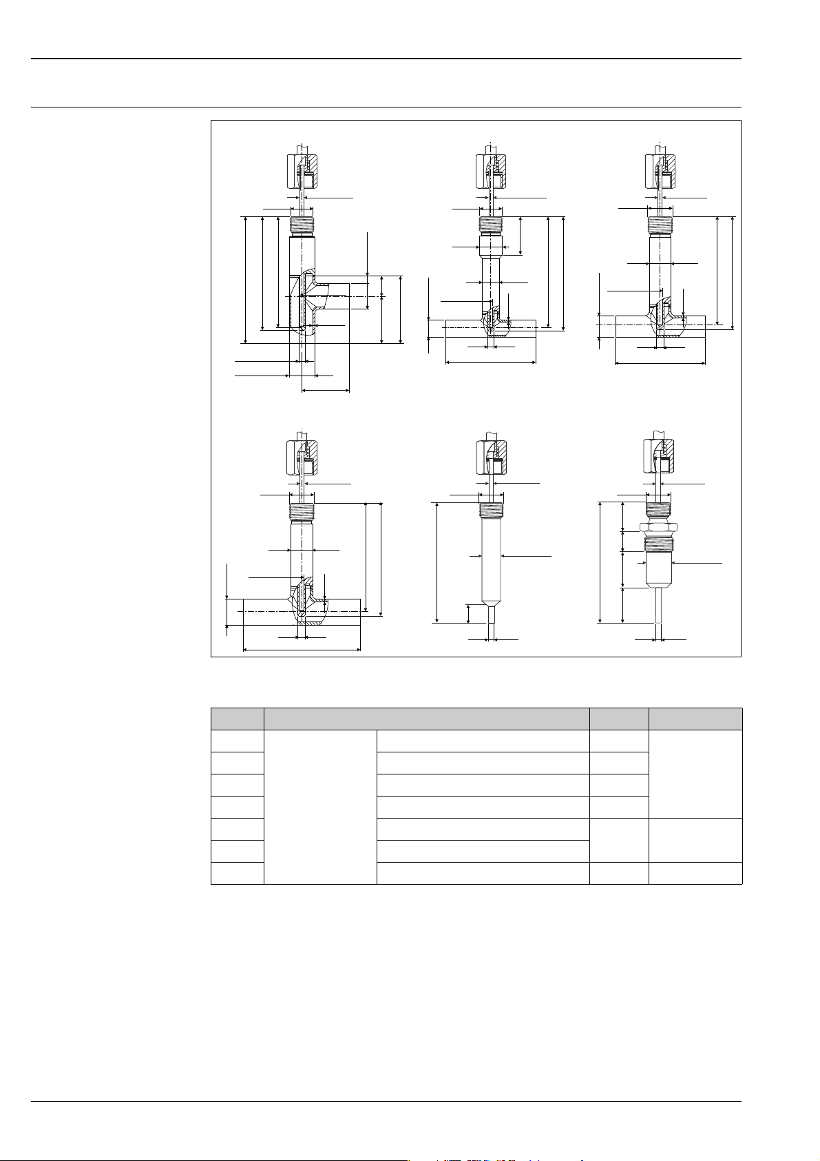
TMR35 thermowells - All dimensions in mm (in)
Item No. TMR35 version P
CB Version with spring-
TB Thermowell version T-piece DN10 -
TC Thermowell version T-piece DN15 -
TD Thermowell version T-piece DN25 -
WA Thermowell cylindric, TL = 70 mm (2.76 in)
WB Thermowell cylindric, TL = 85 mm (3.35 in)
WC Thermowell metal to metal - 16 bar (232 psi)
1) Permitted flow velocity = 40 m/s (131 ft/s)
12 Endress+Hauser
loaded cap-nut G3/8"
Thermowell version corner piece DN15 -
3-A
marked
max.
25 bar (363 psi)
250 bar
(3626 psi)
A0018305
1)
Page 13

TMR31, TMR35
Human interface
Display elements No display elements are present directly on the device.
The measured value and other displays can be called up using the ReadWin 2000 PC software.
Operating elements No operating elements are present directly on the display. The temperature transmitter is configured
by remote operation, without an additional power supply using the ReadWin 2000 PC software.
Remote operation Configuration
Configuration kit TXU10-BA with PC operating program (ReadWin 2000).
Interface
PC interface: TTL/USB connecting cable with plug connector.
Configurable parameters
Measurement dimension (°C/°F), Measuring range, fail-safe mode, output signal (4 to 20 mA / 20 to
4 mA), filter, offset, tag name (8 characters), output simulation.
Certificates and approvals
CE-Mark The measuring system meets the legal requirements of the applicable EC guidelines. These are listed
in the corresponding EC Declaration of Conformity together with the standards applied.
Endress+Hauser confirms successful testing of the device by affixing to it the CE mark.
Hygiene standard EHEDG certification TYPE EL CLASS I. Permitted process connections in accordance with EHEDG, see
"Process connections" section 11
• 3-A authorization no. 1144, 3-A sanitary standard. Permitted process connections in accordance
with 3-A, see also "Process connections" section
• 3-A marked process connections 11
• Product contact surfaces are FDA-compliant. For the enclosures lies no FDA-Conformity form the
PCM before
Marine approval
Other standards and guidelines
UL UL recognized component (see www.ul.com/database - search for Keyword "E225237")
For further details on the available "Type Approval Certificiates" (DNVGL, BV, etc.), please contact your
nearest Endress+Hauser sales organisation. All relevant data for marine approval can be found in
separate "Type Approval Certificiates". If required, please request copies from us or your
Endress+Hauser sales organisation.
• IEC 60751: Industrial platinum resistance thermometers
• IEC 60529: Degree of protection provided by housing (IP code)
• IEC 61010-1: Safety requirements for electrical equipment for measurement,
control and laboratory use
• IEC/EN 61326 Series: Electromagnetic compatibility (EMC requirements)
• NAMUR: Standards working group for measurement and control technology in the chemical
industry
The UL applies only for the compact thermometers TMR31, TMR35 with electronics and
4 to 20 mA output signal.
Endress+Hauser 13
Page 14
TMR31, TMR35
G½”
25 (0.98)
36 (1.42)
30 (1.18)
6 (0.24)
4
3
2
1
AF24
25 (0.98)
30 (1.18)
G½”
6 (0.24)
Ordering information
Detailed ordering information is available from the following sources:
• In the Product Configurator on the Endress+Hauser website:
www.endress.com
Select your country Products Select measuring technology, software or
components Select the product (picklists: measurement method, product family etc.) Device
support (right-hand column): Configure the selected product The Product Configurator for the
selected product opens.
• From your Endress+Hauser Sales Center: www.addresses.endress.com
Product Configurator - the tool for individual product configuration:
• Up-to-the-minute configuration data
• Depending on the device: Direct input of measuring point-specific information such as
measuring range or operating language
• Automatic verification of exclusion criteria
• Automatic creation of the order code and its breakdown in PDF or Excel output format
• Ability to order directly in the Endress+Hauser Online Shop
Accessories
Various accessories, which can be ordered with the device or subsequently from Endress+Hauser, are
available for the device. Detailed information on the order code in question is available from your local
Endress+Hauser sales center or on the product page of the Endress+Hauser website:
www.endress.com.
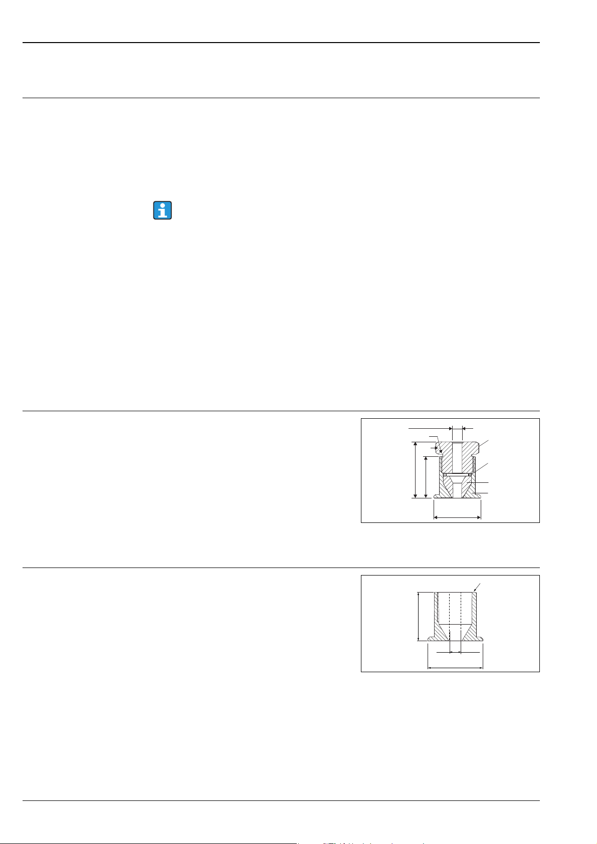
Welding boss with sealing taper for TMR31
Collar welding boss for TMR31
All dimensions in mm (in).
EN10204-3.1 = Material certificate (melt analysis)
Collar welding boss moveable with sealing taper,
washer and pressure screw G½",
material of wetted parts: 316L, PEEK
max. process pressure: 10 bar (145 psi)
Order number with pressure screw: 51004751
Order number without pressure screw:
51004752
1) pressure screw, 303/304
2) washer, 303/304
3) sealing taper, PEEK
4) collar welding boss, 316L
Material of parts in contact with process: 316L
Order number: 51004752
A0020709-EN
A0020710
14 Endress+Hauser
Page 15
TMR31, TMR35
G½”
45 (1.77 )
15 (0.59)
6 (0.24)
+1
+0.04
AF14
AF27
30 (1.18)
16 (0.63)
34 (1.34)
15 (0.6)
G½”
26 (1.02)
50 (1.97)
32 (1.26)
G ¾”
ISO 228
21 (0.8)
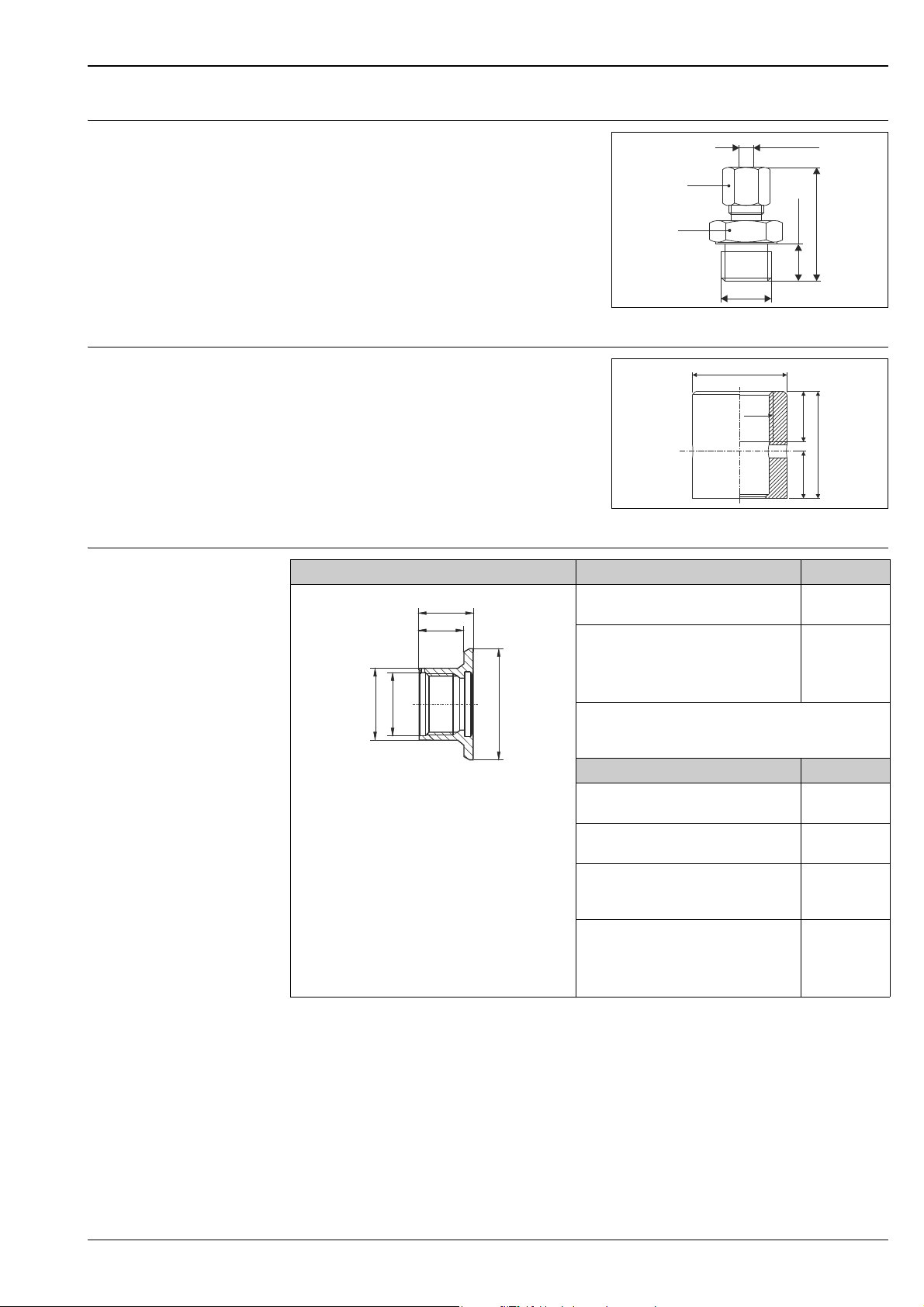
Coupling for TMR31
Welding boss with sealing taper (metal-metal) for TMR35
Weld-in adapter for TMR35 process connection
Clamping ring, movable, different process
connections, e.g. G½", G¾", G1", NPT½"
coupling and parts in contact with process: 316L
Order number: TA50-HB
A0020174-EN
Welding boss for G½" thread
Seal, metal-metal,
Material of parts in contact with process: 316L/
1.4435
Max. process pressure 16 bar (232 psi)
Order no. 71405560
A0006621
Dimensions Version Order number
• max. 25 bar (362 psi) / max. 150 °C (302 °F)
• max. 40 bar (580 psi) / max. 100 °C (212 °F)
AISI 316L (1.4435) with inspection
certificate EN10204-3.1 material
Silicone O-ring ⌀14.9 x 2.7 mm (0.59 x
0.11 in), material: VMQ75, FDA
• For this version a simple replacement
of the seal is possible.
FDA approved materials according to 21 CFR Part 175178
3-A and EHEDG marked
A0012605
Alternative seals Order number
⌀15.08 x 2.62 mm (0.62 x 0.1 in)
Material: EPDM, FDA
⌀15.08 x 2.62 mm (0.62 x 0.1 in)
Material: Viton, FDA
⌀14.9 x 2.7 mm (0.59 x 0.11 in)
Material: Silicone, VMQ80, FDA,
USP Class VI
Pressure ring, material: 316L
• The seal with pressure ring enables
easy exchange of defective sealing
rings.
52018765
52021717
(5 pieces)
MVT2L1934
(5 pieces)
MVT2L1942
(5 pieces)
71086117
(3 pieces)
52027421
Endress+Hauser 15
Page 16
TMR31, TMR35
–0.4
55 (2.17 )
32 (1.26)
G ¾”
ISO 228
–0.016
26 (1.02)
21 (0.8)
–
Weld-in adapter for TMR35 process connection
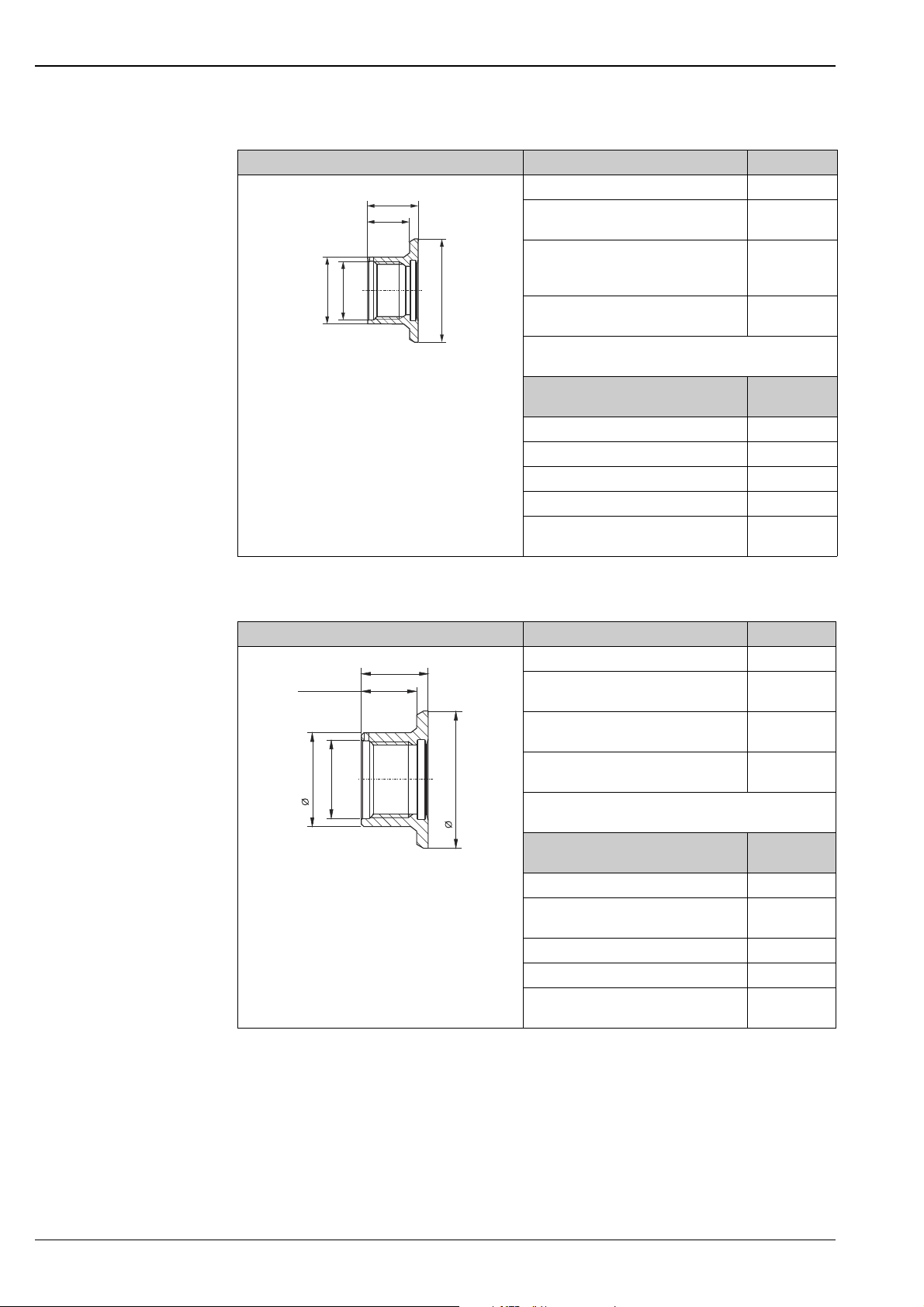
Welding boss G¾", d=55 with flange for flush-mounted installation for sealing surface.
Dimensions Version Order number
AISI 316L (1.4435) 52001052
• max. 25 bar (362 psi) / max. 150 °C (302 °F)
• max. 40 bar (580 psi) / max. 100 °C (212 °F)
AISI 316L (1.4435) with inspection
certificate EN10204-3.1 material
Silicone O-ring, ⌀21.89 x 2.62 mm
(0.86 x 0.10 in)
Material: VMQ70, FDA
Sensor dummy for welding the welding
boss
FDA approved materials according to 21 CFR Part
A0012603
177.1550/2600, 3-A and EHEDG marked
Alternative seals ⌀21.89 x 2.62 mm
(0.86 x 0.1 in)
Material: EPDM, FDA MVT2L1148
Material: Kalrez Comp. 2035 MVT2L0666
Material: Viton MVT2L0655
Material: Viton/FEP-FEK 75 Shore MVT2L1748
Material: Silicone, VMQ23-70, FDA,
USP Class VI
52011897
52014473
(5 pieces)
MVT2L0692
Order number
71086100
(3 pieces)
Welding boss G1", d=60 with flange for flush-mounted installation with sealing surface.
Dimensions Version Order number
29.6 (1.17)
24.6 (0.97)
G1
41 (1.61)
ISO 228
0.4 0.016
60 (2.36- )
• max. 25 bar (363 psi) / max. 150 °C (302 °F)
• max. 40 bar (580 psi) / max. 100 °C (212 °F)
AISI 316L (1.4435) 52001051
AISI 316L (1.4435) with inspection
certificate EN10204-3.1 material
Silicone O-ring, ⌀28.17 x 3.53 (1.11 x
0.14"), material: VMQ70, FDA
Sensor dummy for welding the welding
boss
FDA approved materials according to 21 CFR Part
177.1550/2600; EHEDG, 3-A marked
Alternative seals ⌀28.17 x 3.53 (1.11 x
A0008957
0.14")
Material: EPDM70, FDA MVT2L0920
Material: Viton665, FDA MVT2L0705
Material: Viton971, V, FDA MVT2L1682
Material: Kalrez comp. 4079 MVT2L0567
Material: Silicone, VMQ23-70, FDA,
USP Class VI
52011896
52014472
(5 pieces)
MVT2L0691
Order number
(5 pieces)
71086102
(3 pieces)
16 Endress+Hauser
Page 17
TMR31, TMR35
D
D
D
L
L
4.5 (0.18)
3.1 (0.12)
3.1 (0.12)
4.5 (0.18)
G 3/8”
G 3/8”
T-piece
(straight)
Corner
piece
20
(0.79)
41
(1.61)
35 (1.38)
14.8
(0.58)
1
2 (WH) nc
2
1 (BN) +
4
3 (BU) -
3
4 (BK) nc
1
2 (WH) nc
2
1 (BN) +
4
3 (BU) -
3
4 (BK) nc
A
B
USB
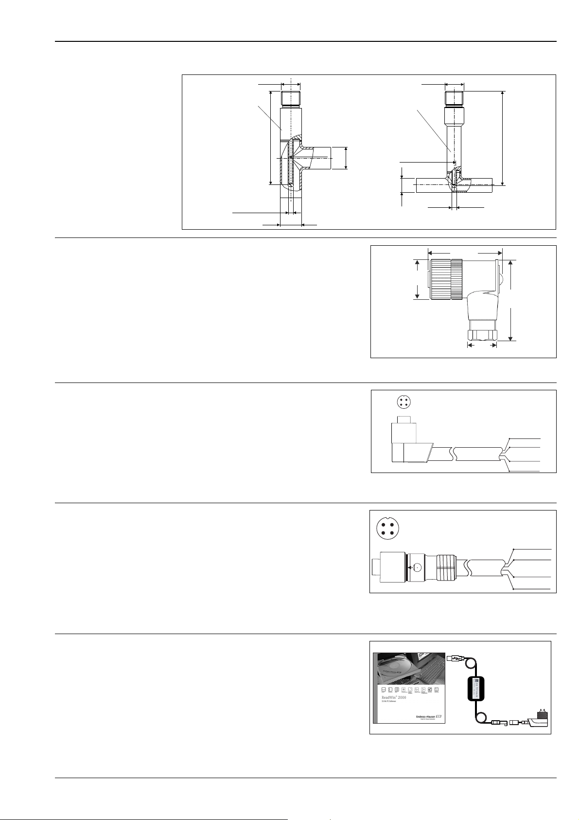
Weld-in pipe + thermowell TT411
Coupling
Connecting cable (preassembled)
Cordset
Coupling M12x1 for simple user installable
assembly of the connecting cable; elbowed;
connection to M12x1 housing connector
IP67, PG7
Order number: 51006327
PVC cable, 4 x 0.34 mm2 (22 AWG) with M12x1
coupling; elbowed; screw plug;
length 5 m (16.4 ft); IP67
Order number: 51005148
Core colours:
- 1 = BN brown
- 2 = WH white
- 3 = BU blue
- 4 = BK black
PVC cable, 4 x 0.34 mm2 (22 AWG) with M12x1
coupling nut from stainless steel; straight female
connector type; screw plug;
length 5 m (16.4 ft); IP69K
Order number: 71217708
Core colours:
- 1 = BN brown
- 2 = WH white
- 3 = BU blue
- 4 = BK black
A0020722
A0020723
A0020725
Configuration kit
• Configuration kit for PC-programmable
transmitters - ReadWin 2000 setup program
and interface cable (4 pin plug) for PCs with
USB port; with adapter for compact
thermometers with M12x1 thread;
Order code: TXU10-BA
Endress+Hauser 17
• ReadWin 2000 can be downloaded free of
charge directly from the internet at the
following address: www.endress.com/
readwin
A0028635
Page 18

TMR31, TMR35
Service-specific accessories
Accessories Description
Applicator Software for selecting and sizing Endress+Hauser measuring devices:
• Calculation of all the necessary data for identifying the optimum measuring
device: e.g. pressure loss, accuracy or process connections.
• Graphic illustration of the calculation results
Administration, documentation and access to all project-related data and
parameters over the entire life cycle of a project.
Applicator is available:
• Via the Internet: https://wapps.endress.com/applicator
• On CD-ROM for local PC installation.
Konfigurator
+temperature
Software for selecting and configuring the product depending on the measuring
task, supported by graphics. Includes a comprehensive knowledge database and
calculation tools:
• For temperature competence
• Quick and easy design and sizing of temperature measuring points
• Ideal measuring point design and sizing to suit the processes and needs of a
wide range of industries
The Konfigurator is available:
On request from your Endress+Hauser sales office on a CD-ROM for local PC
installation.
System components
W@M
FieldCare FDT-based plant asset management tool from Endress+Hauser.
Life cycle management for your plant
W@M supports you with a wide range of software applications over the entire
process: from planning and procurement, to the installation, commissioning and
operation of the measuring devices. All the relevant device information, such as
the device status, spare parts and device-specific documentation, is available for
every device over the entire life cycle.
The application already contains the data of your Endress+Hauser device.
Endress+Hauser also takes care of maintaining and updating the data records.
W@M is available:
• Via the Internet: www.endress.com/lifecyclemanagement
• On CD-ROM for local PC installation.
It can configure all smart field units in your system and helps you manage them.
By using the status information, it is also a simple but effective way of checking
their status and condition.
For details: see Operating Instructions BA00027S and BA00059S
Accessories Description
Field display unit RIA16 The display unit records the analog measuring signal from the head transmitter and
shows this on the display. The LC display shows the current measured value in digital
form and as a bar graph indicating a limit value violation. The display unit is looped
into the 4 to 20 mA circuit and gets the required energy from there.
For details: see the Technical Information document TI00144R/09/en
Field indicator RIA15 Loop-powered field indicator for 4 to 20 mA circuit, panel mounting.
For details: see the Technical Information document TI01043K/09/en
18 Endress+Hauser
Page 19

TMR31, TMR35
RN221N Active barrier with power supply for safe separation of 4 to 20 mA standard signal
circuits. Offers bidirectional HART®
transmission.
For details: see the Technical Information document TI0073R and
Operating Instructions BA00202R
RNS221 Supply unit for powering two 2-wire measuring devices solely in the non-Ex area.
Bidirectional communication is possible via the HART® communication jacks.
For details: see the Technical Information document TI0081R and Brief
Operating Instructions KA00110R
Documentation
Operating manual "Easytemp TMR31, TMR35" (BA00215R/09)
Endress+Hauser 19
Page 20

TMR31, TMR35
www.addresses.endress.com
 Loading...