

Page 1
TI01349T/09/EN/02.18
71418572
2018-11-05
Products
Solutions Services
Technical Information
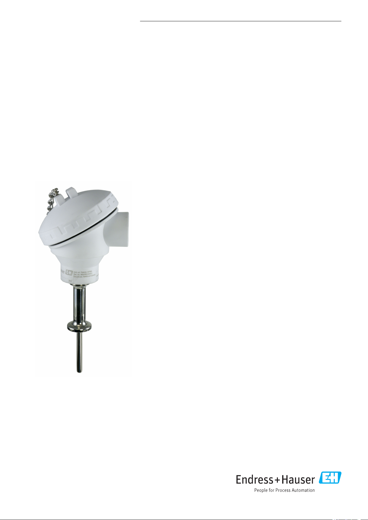
iTHERM TM402
Resistance thermometer for hygienic and aseptic
applications
Imperial version with basic technology
for all standard applications, permanent insert
Applications
• Specially designed for use in hygienic and aseptic applications in the Food &
Beverages and Life Sciences industries
• Measuring range: –50 to +200 °C (–58 to +392 °F)
• Pressure range up to 40 bar (580 psi)
• Protection class: up to IP69K
• Can be used in non-hazardous areas
Temperature transmitter
All Endress+Hauser transmitters are available with enhanced accuracy and reliability
compared to directly wired sensors. Easy customizing by choosing one of the
following outputs and communication protocols:
• Analog output 4 to 20 mA, HART
• Field transmitters with HART® or FOUNDATION Fieldbus™ protocol for highest
reliability in harsh industrial environments. Backlit display with large measured
value, bargraph and fault condition indication for ease of reading.
Your benefits
• Excellent value for money and fast delivery
• User-friendly and reliable from product selection to maintenance
• International certification: hygiene standards as per 3-A®, EHEDG, ASME BPE,
FDA, TSE Certificate of Suitability
• Wide range of process connections
®
Page 2

Table of contents
iTHERM TM402
Function and system design ................... 3
iTHERM Hygiene line ........................... 3
Measuring principle ............................ 3
Measuring system ............................. 3
Input ..................................... 4
Measured variable ............................. 4
Measuring range .............................. 4
Output ................................... 4
Output signal ................................ 4
Family of temperature transmitters ................. 4
Wiring ................................... 5
Wiring diagrams for RTD ........................ 5
Cable entries ................................ 6
Connector .................................. 6
Overvoltage protection .......................... 6
Performance characteristics ................... 6
Reference conditions ........................... 6
Maximum measured error ....................... 7
Influence of ambient temperature .................. 7
Self heating ................................. 7
Response time ............................... 8
Calibration .................................. 9
Insulation resistance ........................... 9
Certificates and approvals ................... 19
CE mark ................................... 19
Hygiene standard ............................ 19
Other standards and guidelines ................... 19
Parts in contact with the medium .................. 19
CRN approval ............................... 19
Surface purity ............................... 19
Material resistance ........................... 19
Material certification .......................... 19
Calibration ................................. 19
Ordering information ....................... 20
Accessories ............................... 21
Device-specific accessories ...................... 21
Communication-specific accessories ................ 21
Service-specific accessories ...................... 22
System components ........................... 23
Documentation ............................ 24
Installation ................................ 9
Orientation ................................. 9
Installation instructions ......................... 9
Environment .............................. 11
Ambient temperature range ..................... 11
Storage temperature .......................... 11
Humidity .................................. 11
Climate class ............................... 11
Degree of protection .......................... 11
Shock and vibration resistance .................... 12
Electromagnetic compatibility (EMC) ............... 12
Process .................................. 12
Process temperature range ...................... 12
Thermal shock .............................. 12
Process pressure range ......................... 12
Medium - state of aggregation .................... 13
Mechanical construction .................... 14
Design, dimensions ........................... 14
Weight ................................... 14
Material .................................. 14
Surface roughness ............................ 15
Terminal heads .............................. 15
Process connections ........................... 16
2 Endress+Hauser
Page 3
iTHERM TM402
mm
inch
mm
inch
Function and system design
iTHERM Hygiene line
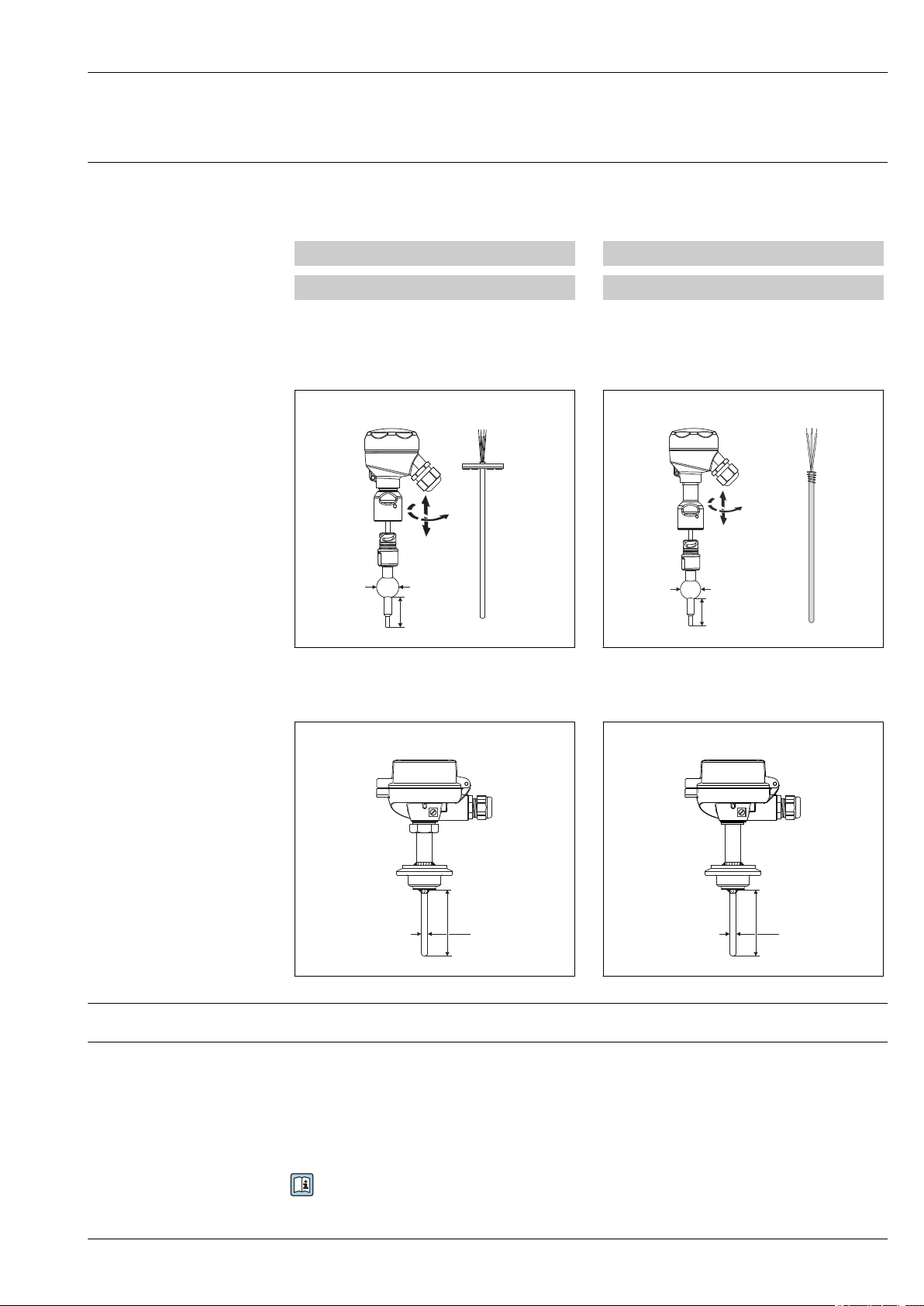
This thermometer is part of the product line of modular thermometers for hygienic and aseptic
applications.
Differentiating factors when selecting a suitable thermometer
TM4x1 TM4x2
Metric version Imperial version
↓ ↓
TM41x characterizes the device that uses cutting-edge technology, with features such as a replaceable insert,
quick-fastening extension neck (iTHERM QuickNeck), vibration-resistant and fast-response sensor technology
(iTHERM StrongSens and QuickSens) and approval for use in hazardous areas
TM411
TM412
Measuring principle
Measuring system
A0018239
↓ ↓
TM40x characterizes the device that uses basic technology, with features such as a fixed, non-replaceable
insert, application in non-hazardous areas, standard extension neck, low-cost unit
TM401
A0018692
TM402
A0018691
A0018693
Endress+Hauser offers a complete portfolio of optimized components for the temperature measuring
point – everything you need for the seamless integration of the measuring point into the overall
facility. This includes:
• Power supply unit/barrier
• Display units
• Data managers
• Overvoltage protection
For more information, see the brochure 'System Products and Data Managers - Solutions for the
loop' (FA00016K)
Endress+Hauser 3
Page 4
iTHERM TM402
FieldCare
Memograph M
RSG45
RIA15
TM4xx
PLC
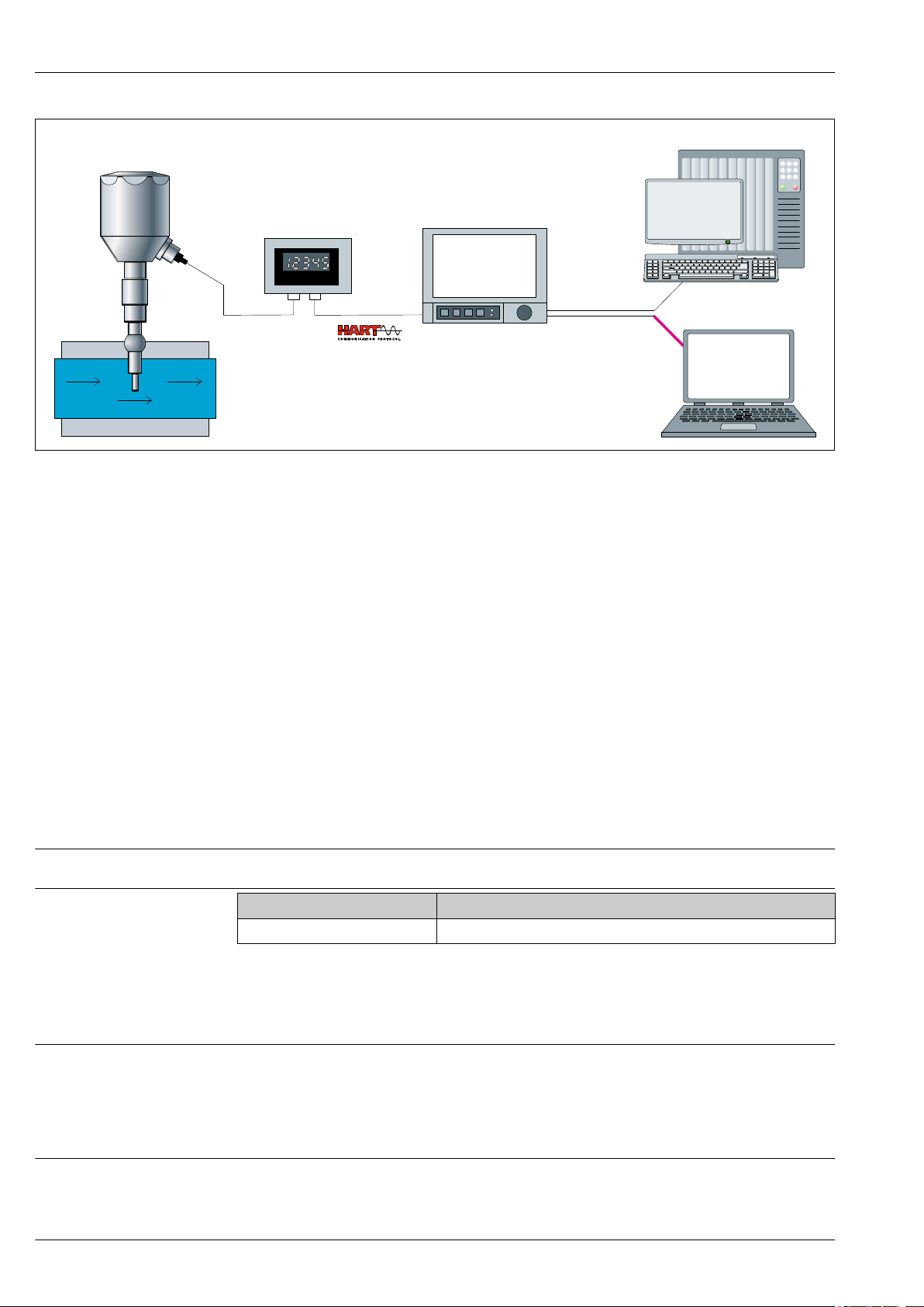
1 Example of application, measuring point layout with additional Endress+Hauser components
A0033768
Measured variable
Measuring range
• iTHERM TM4x2: Installed RTD thermometer with integrated HART® head transmitter
• Display unit RIA15:
- Display of 4 to 20 mA measured values or HART® process variables
- Loop-powered
- Voltage drop ≤1 V (HART® ≤1.9 V)
• Data Management Memograph M RSG45:
- Tamper-proof data storage and access (FDA 21 CFR 11)
- HART® gateway functionality; Up to 40 HART® devices connected at a time
- Communication capabilities: Modbus, Profibus DP, PROFINET, EtherNet/IP
• PLC / FieldCare: Field Data Manager Software MS20 - Automatic service for report generation,
printing reports, read out of data, storing of data, secure export, pdf generation Read out
measured data via online interface or from mass storage Online visualization of instantaneous
values (“live data”) . More information on this can be found in the Technical Information, see
"Documentation".
Input
Temperature (temperature-linear transmission behavior)
Sensor type Measuring range
Pt100 thin-film –50 to +200 °C (–58 to +392 °F)
Output signal
Family of temperature transmitters
Output
Generally, the measured value can be transmitted in one of two ways:
• Directly-wired sensors - sensor measured values forwarded without a transmitter.
• Via all common protocols by selecting an appropriate Endress+Hauser iTEMP temperature
transmitter. All the transmitters listed below are mounted directly in the terminal head and wired
with the sensory mechanism.
Thermometers fitted with iTEMP transmitters are an installation-ready complete solution to
improve temperature measurement by significantly increasing accuracy and reliability, when
compared to direct wired sensors, as well as reducing both wiring and maintenance costs.
4 Endress+Hauser
Page 5
iTHERM TM402
3
5
6
RTD
3
4
5
6
RTD
1
2
3-wire
4-wire
Power supply
head transmitter and
analog output 4 to 20 mA,
or bus connection
(red) (red)
(red) (red)
(white) (white)
(white)
mA
1 x Pt 100
1 x Pt 100
red
red
white
4 wires 3 wires
red
white
red
white
PC programmable head transmitters
They offer a high degree of flexibility, thereby supporting universal application with low inventory
storage. The iTEMP transmitters can be configured quickly and easily at a PC. Endress+Hauser offers
free configuration software which can be downloaded from the Endress+Hauser Website. More
information can be found in the Technical Information. → 24
HART® programmable head transmitters
The transmitter is a 2-wire device with one or two measuring inputs and one analog output. The
device not only transfers converted signals from resistance thermometers and thermocouples, it also
transfers resistance and voltage signals using HART® communication. It can be installed as an
intrinsically safe apparatus in Zone 1 hazardous areas and is used for instrumentation in the
terminal head (flat face) as per DIN EN 50446. Swift and easy operation, visualization and
maintenance by using universal device configuration tools like FieldCare, DeviceCare or
FieldCommunicator 375/475. For more information, see the Technical Information. → 24
Advantages of the iTEMP transmitters:
• Dual or single sensor input (optionally for certain transmitters)
• Unsurpassed reliability, accuracy and long-term stability in critical processes
• Mathematical functions
• Monitoring of the thermometer drift, sensor backup functionality, sensor diagnostic functions
• Sensor-transmitter matching for dual sensor input transmitter, based on Callendar/Van Dusen
coefficients
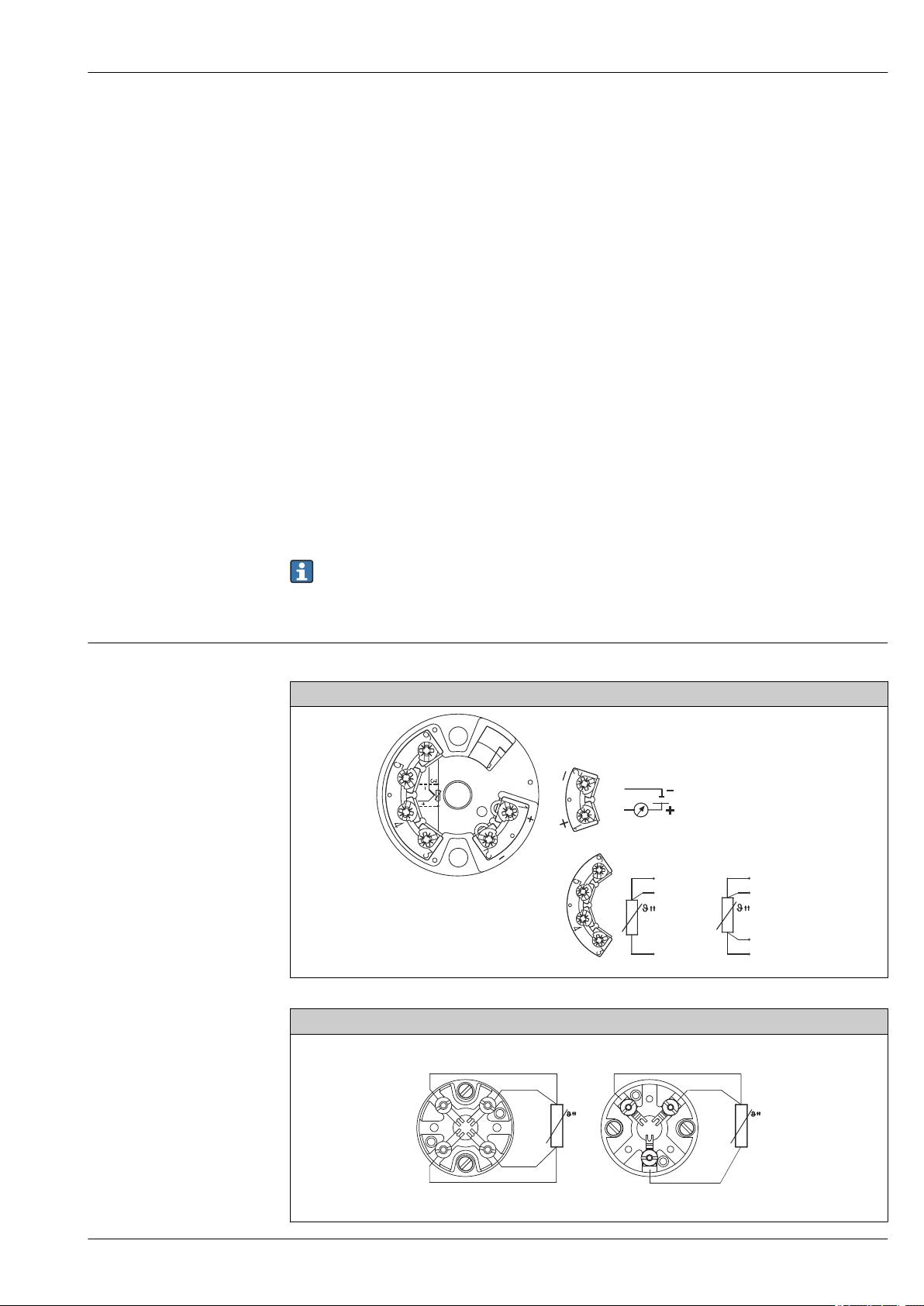
Wiring diagrams for RTD
Wiring
• According to the 3-A® Standard electrical connecting cables must be smooth, corrosionresistant and easy to clean.
• Grounding or shield connections are possible via special ground terminals on the terminal
head. → 15
Type of sensor connection
Head mounted transmitter TMT18x (single input)
A0016433-EN
Endress+Hauser 5
Terminal block mounted
A0019262-EN
Page 6
iTHERM TM402
1 BN
2 GNYE
3 BU
4 GY
1
4 3
2
Cable entries
Connector
See the 'Terminal head' section → 15
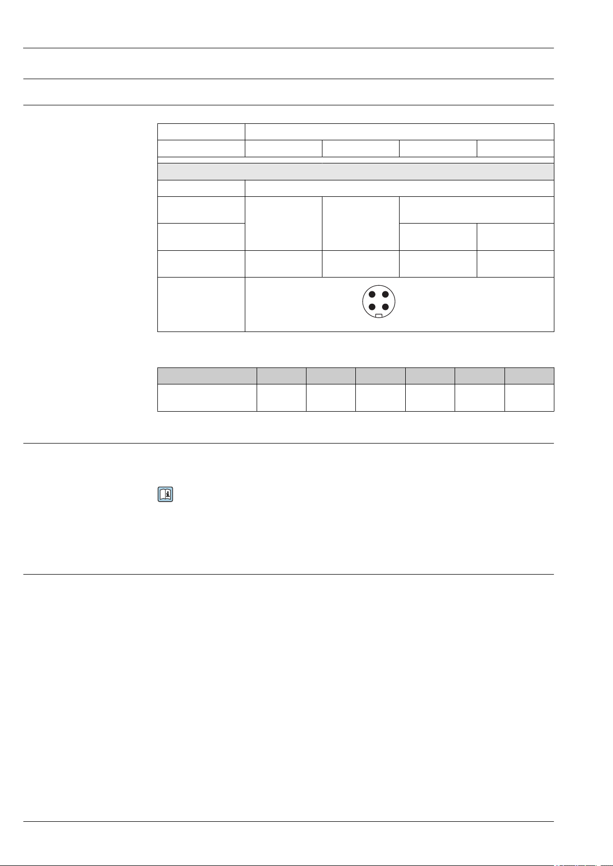
PIN assignment of the M12 connectors, connection combinations
Connector M12 connector 4‐pin
PIN number 1 2 3 4
Electrical connection (terminal head)
Flying leads Not connected (not insulated)
3-wire terminal block
(1x Pt100)
4-wire terminal block
(1x Pt100)
1x TMT 4 to 20 mA or
PIN position and color
HART
code
®
RD RD
WH WH
+ i - i
WH
Abbreviations
i RD WH BN GNYE BU GY
Insulated
1)
Red White Brown Green-
yellow
Blue Gray
A0018929
Overvoltage protection
Reference conditions
1) Wires marked 'i' are not connected and are insulated with heat shrink tubes.
To protect against overvoltage in the power supply and signal/communication cables for the
thermometer electronics, Endress+Hauser offers the HAW562 surge arrester for DIN rail mounting
and the HAW569 for field housing installation.
For more information see the Technical Information 'HAW562 Surge arrester' TI01012K and
'HAW569 Surge arrester' TI01013K.
Performance characteristics
These data are relevant for determining the accuracy of the temperature transmitters used. More
information on this can be found in the Technical Information of the iTEMP temperature
transmitters.
6 Endress+Hauser
Page 7
iTHERM TM402
A
AA
-200 -100 0 100 200 300 400 500 600°C
0.5
1.0
1.5
2.0
B
2.5
3.0
- 0.5
- 1.0
- 1.5
- 2.0
- 2.5
- 3.0
B
A
AA
Max. deviation (°C)
Max. deviation (°C)
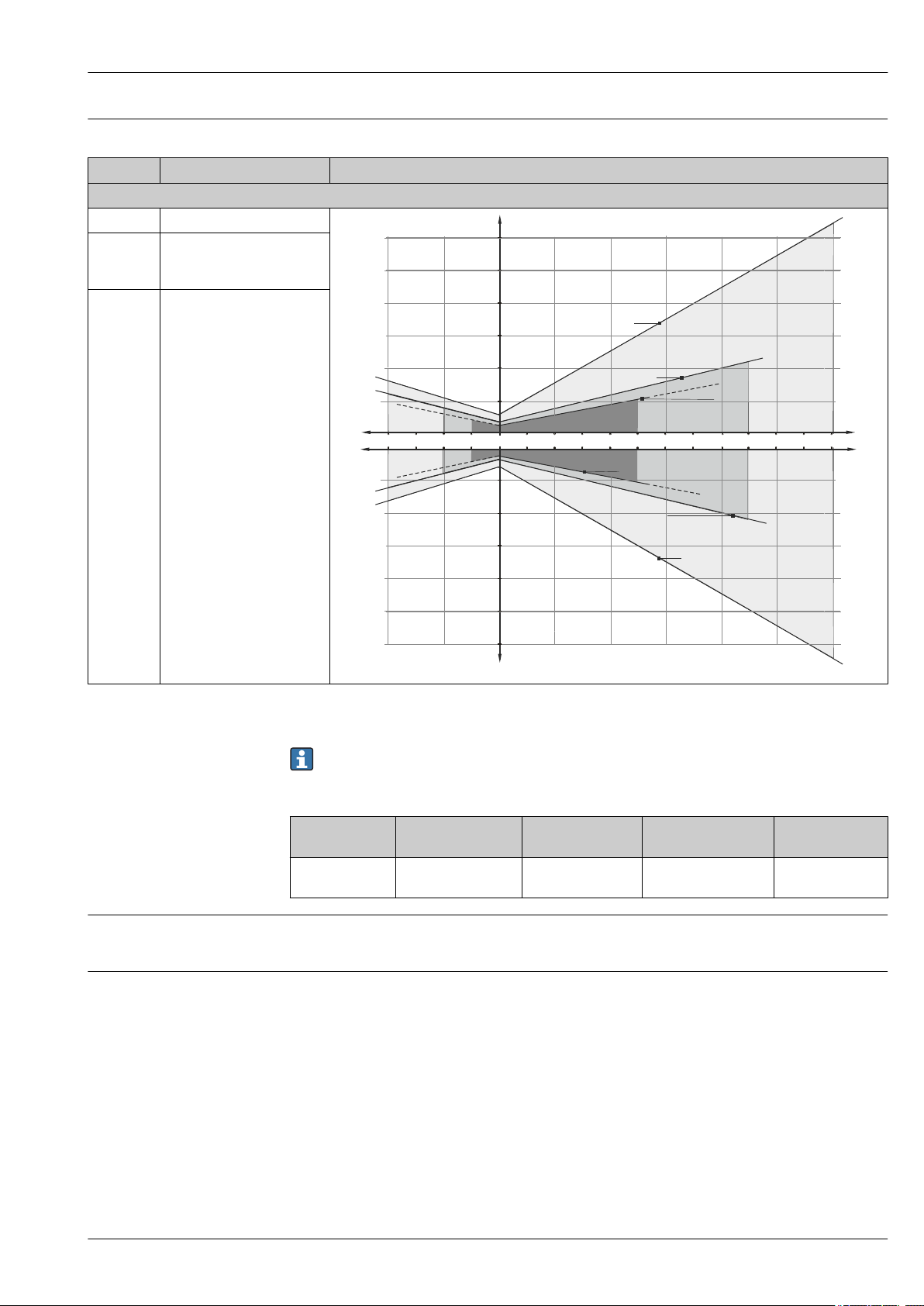
Maximum measured error
RTD resistance thermometer corresponding to IEC 60751
Class max. Tolerances (°C) Characteristics
RTD maximum error type TF
Cl. A ± (0.15 + 0.002 · |t|
Cl. AA,
± (0.1 + 0.0017 · |t|)
1)
)
1)
former 1/3
Cl. B
Cl. B ± (0.3 + 0.005 · |t|
1)
)
1) |t| = absolute value °C
For measurement errors in °F, calculate using equations in °C, then multiply the outcome by 1.8.
Temperature ranges for compliance with the tolerance classes
Sensor type Operating
temperature range
Influence of ambient temperature
Self heating
Pt100 thin film
sensor (TF)
–50 to 200 °C
(–58 to 392 °F)
Depends on the head transmitter used. For details, see Technical Information. → 24
RTD elements are passive resistances that are measured using an external current. This
measurement current causes a self-heating effect in the RTD element itself which in turn creates an
additional measurement error. In addition to the measurement current, the size of the measurement
error is also affected by the temperature conductivity and flow velocity of the process. This selfheating error is negligible when an Endress+Hauser iTEMP temperature transmitter (very small
measurement current) is connected.
Class B Class A Class AA
- –30 to 200 °C
-
(–22 to 392 °F)
A0008588-EN
Endress+Hauser 7
Page 8
iTHERM TM402
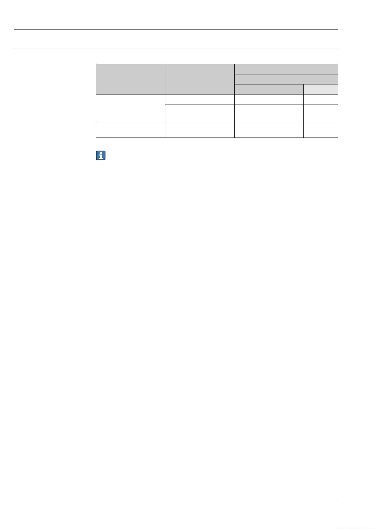
Response time
Tests in water at 0.4 m/s (1.3 ft/s), according to IEC 60751; 10 K temperature step change.
1x Pt100 thin-film sensor
Pipe diameter Shape of tip
Straight 5 s 11 s
6.35 mm (¹⁄₄ in)
9.53 mm (³⁄₈ in)
Reduced 4.76 mm (³⁄₁₆ in) x
19.05 mm (0.75 in)
Reduced 4.76 mm (³⁄₁₆ in) x
19.05 mm (0.75 in)
Response time
t
50
3.5 s 9 s
5 s 10.5 s
Response time without transmitter.
t
90
8 Endress+Hauser
Page 9

iTHERM TM402
Calibration
Calibration of thermometers
Calibration involves comparing the measured values of a device under test (DUT) with those of a
more precise calibration standard using a defined and reproducible measurement method. The aim is
to determine the deviation of the DUT's measured values from the true value of the measured
variable. Two different methods are used for thermometers:
• Calibration at fixed-point temperatures, e.g. at the freezing point of water at 0 °C,
• Calibration compared against a precise reference thermometer.
The thermometer to be calibrated must display the fixed point temperature or the temperature of
the reference thermometer as accurately as possible. Temperature-controlled calibration baths with
very homogeneous thermal values, or special calibration furnaces into which the DUT and the
reference thermometer, where necessary, can project to a sufficient degree, are typically used for
thermometer calibrations.
The measurement uncertainty can increase due to heat dissipation errors and short immersion
lengths. The existing measurement uncertainty is listed on the individual calibration certificate.
For accredited calibrations according to ISO17025, the measurement uncertainty shouldn’t be twice
as high as the accredited measurement uncertainty. If this is exceeded, only a factory calibration can
be performed.
Evaluation of thermometers
If a calibration with an acceptable uncertainty of measurement and transferable measurement
results is not possible, Endress+Hauser offers customers a thermometer evaluation measurement
service, if technically feasible. This is the case when:
• The process connections/flanges are too big or the immersion length (IL) is too short to allow the
DUT to be immersed sufficiently in the calibration bath or furnace (see the following table), or
• Due to heat conduction along the thermometer tube, the resulting sensor temperature generally
deviates significantly from the actual bath/furnace temperature.
The measured value of the DUT is determined using the maximum possible immersion depth and the
specific measuring conditions and measurement results are documented on an evaluation certificate.
For the device, Endress+Hauser offers standard calibrations at a reference temperature of
–20 to +200 °C (–4 to +392 °F) based on the ITS90 (International Temperature Scale). Calibrations in
other temperature ranges are available from your Endress+Hauser sales center on request.
Calibrations are traceable to national and international standards. The calibration certificate is
referenced to the serial number of the thermometer.
Insulation resistance
Orientation
Installation instructions
Insulation resistance ≥ 100 MΩ at ambient temperature.
Insulation resistance between the terminals and the outer jacket is measured with a minimum
voltage of 100 V DC.
Installation
No restrictions. However, self-draining in the process must be guaranteed. If there is an opening to
detect leaks at the process connection, this opening must be at the lowest possible point.
The immersion length of the thermometer can influence the accuracy. If the immersion length is too
small then errors in the measurement are caused by heat conduction via the process connection and
the container wall. If installing into a pipe then the immersion length should ideally be half of the
pipe diameter.
Installation possibilities: Pipes, tanks or other plant components
Endress+Hauser 9
Page 10
U
≥ 3°
≥ 3°
1
2
3
4
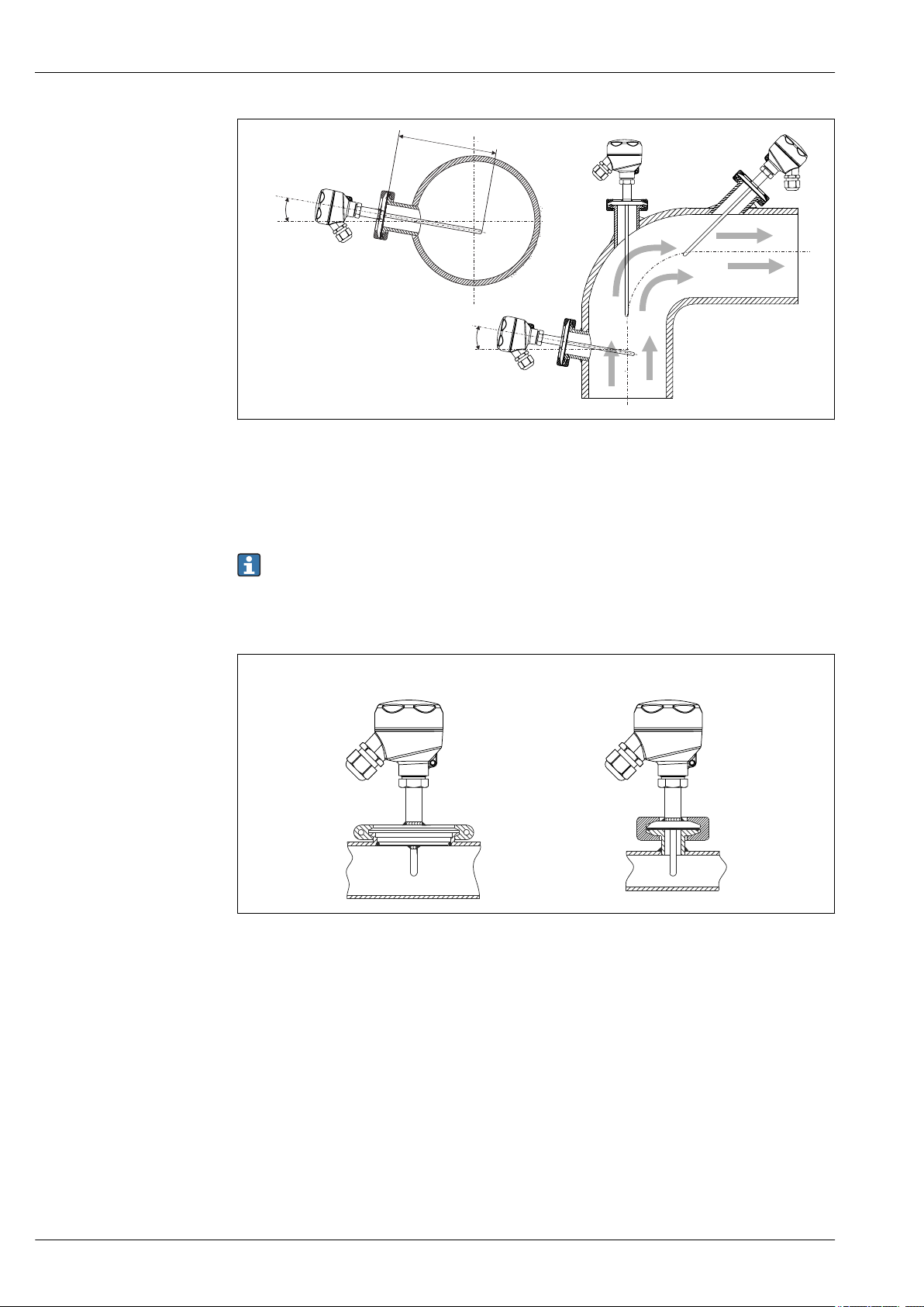
2 Installation examples
1 2
1, 2 Perpendicular to flow direction, installed at a minimum angle of 3° to ensure self-draining
3 On elbows
4 Inclined installation in pipes with a small nominal diameter
U Immersion length
iTHERM TM402
A0008946
In the case of pipes with a small nominal diameter, it is advisable for the tip of the thermometer
to project well into the process so that it extends past the pipe axis. Installation at an angle (4)
could be another solution. When determining the immersion length or installation depth all the
parameters of the thermometer and of the medium to be measured must be taken into account
(e.g. flow velocity, process pressure).
3 Process connections for thermometer installation in pipes with small nominal diameters
1
Varivent® - process connection D = 50 mm for DN25 pipes
2 Clamp or micro-clamp
A0018881
10 Endress+Hauser
Page 11
iTHERM TM402
1 2
3
4
R0.4
R0.4
Pressure ring
Sensor with
milk pipe
connection
Sensor with Varivent
connection
Shaped
gasket
Companion
connection
O-ring
Groove
slip-on nut
Centering ring
Sealing
Companion
connection
Companion
connection
O-ring
Welding boss
Vessel wall
A0011758-EN
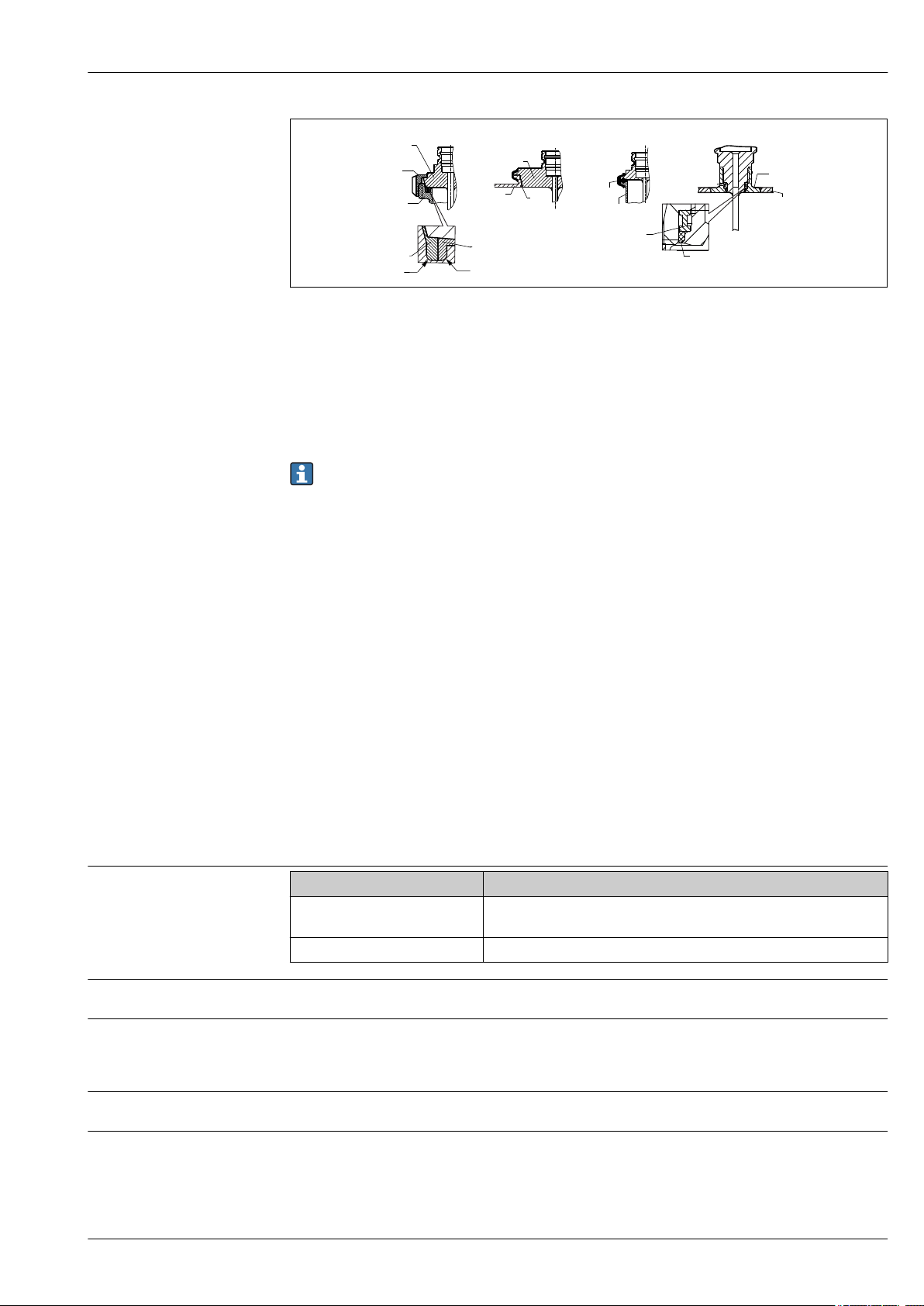
4 Detailed installation instructions for hygiene-compliant installation
1 Sanitary connection according to DIN 11851, only in connection with EHEDG-certified and self-centering
sealing ring
2
Varivent® process connection for VARINLINE® housing
3 Clamp according to ISO 2852, only in connection with seal according to EHEDG position paper
4 Liquiphant-M G1" process connection
The counterpieces for the process connections and the seals or sealing rings are not included in
the scope of supply for the thermometer. Liquiphant M weld-in adapters with associated seal
kits are available as accessories.
Procedure in case of seal failure:
• Disassembling of the thermometer, validated cleaning procedure of thread and sealing ring
groove
• Replacement of the seal or sealing ring
• CIP after re-assembly
In the case of weld-in connections, exercise the necessary degree of care when performing the
welding work on the process side:
• Suitable welding material
• Flush-welded or with welding radius > 3.2 mm (0.13 in)
• No recesses, folds or gaps
• Honed and polished surface, Ra ≤ 0.76 µm (30 µin)
As a general rule, the thermometers should be installed in such a way that does not impact
their ability to be cleaned (the requirements of the 3-A Sanitary Standard must be observed).
The Varivent® and Liquiphant-M weld-in adapter enable flush-mounted installation.
Ambient temperature range
Storage temperature
Humidity
Climate class
Degree of protection
Endress+Hauser 11
Environment
Terminal head Temperature in °C (°F)
Without mounted head
transmitter
With mounted head transmitter –40 to 85 °C (–40 to 185 °F)
For information, see the ambient temperature.
Depends on the transmitter used. If Endress+Hauser iTEMP head transmitters are used:
• Condensation permitted as per IEC 60 068-2-33
• Maximum relative humidity: 95% as per IEC 60068-2-30
As per EN 60654-1, Class C
Max. IP69K, depending on the design (terminal head, connector, etc.)
Depends on the terminal head used and the cable gland or fieldbus
connector, see 'Terminal heads' section → 15
Page 12
iTHERM TM402
Shock and vibration resistance
Electromagnetic compatibility (EMC)
Process temperature range
Thermal shock
Process pressure range
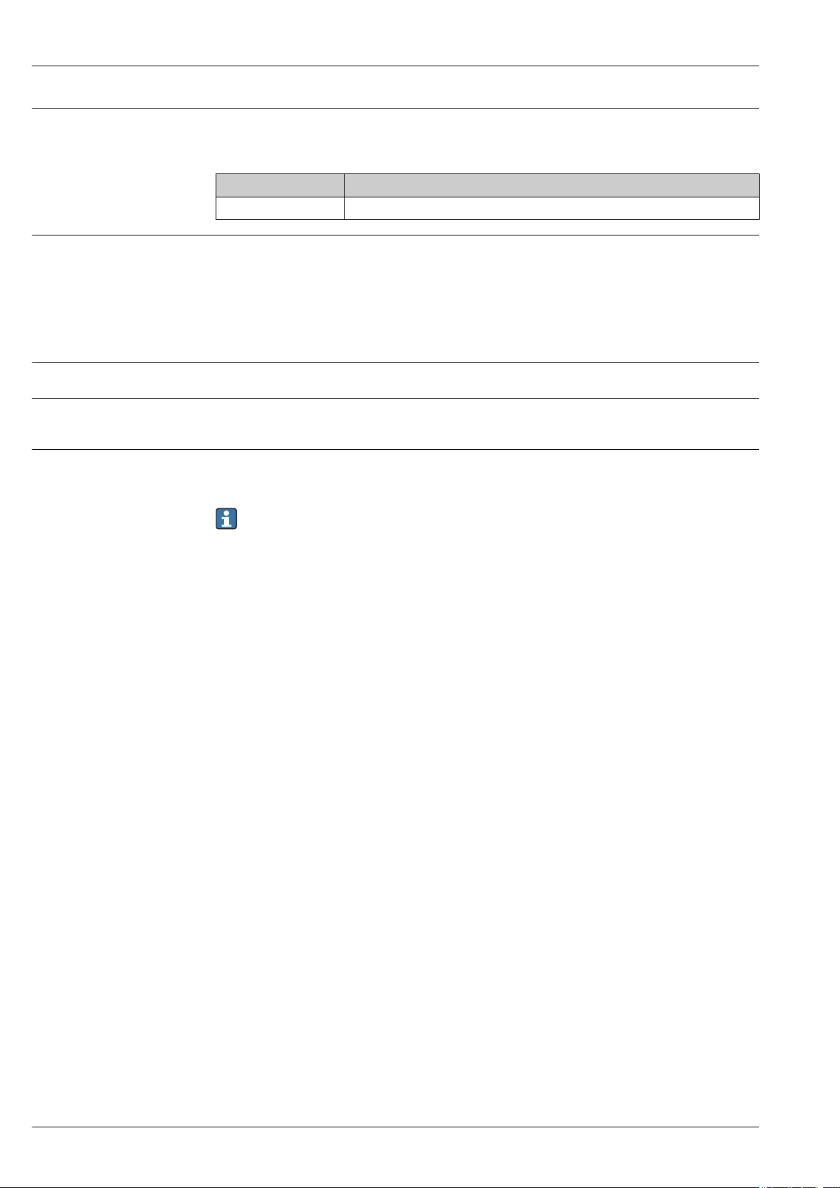
The Endress+Hauser inserts meet the requirements of IEC 60751 which specify shock and vibration
resistance of 3g in the range from 10 to 500 Hz. The vibration resistance at the measuring point
depends on the sensor type and design, see the following table:
Version Vibration resistance for the sensor tip
Pt100 (TF) 30 m/s² (3g)
Depends on the head transmitter used. For details see the Technical Information. → 24
Process
Maximum –50 to +200 °C (–58 to +392 °F)
Thermal shock resistance in CIP/SIP process with a temperature increase from
+5 to +130 °C (+41 to +266 °F) within 2 seconds.
The maximum possible process pressure depends on various influencing factors, such as the design,
process connection and process temperature. For information on the maximum possible process
pressures for the individual process connections, see the 'Process connection' section. → 16
It is possible to check the mechanical loading capacity as a function of the installation and
process conditions online in the Thermowell (TW) Sizing Module for protection tubes in the
Endress+Hauser Applicator software. See 'Accessories' section.
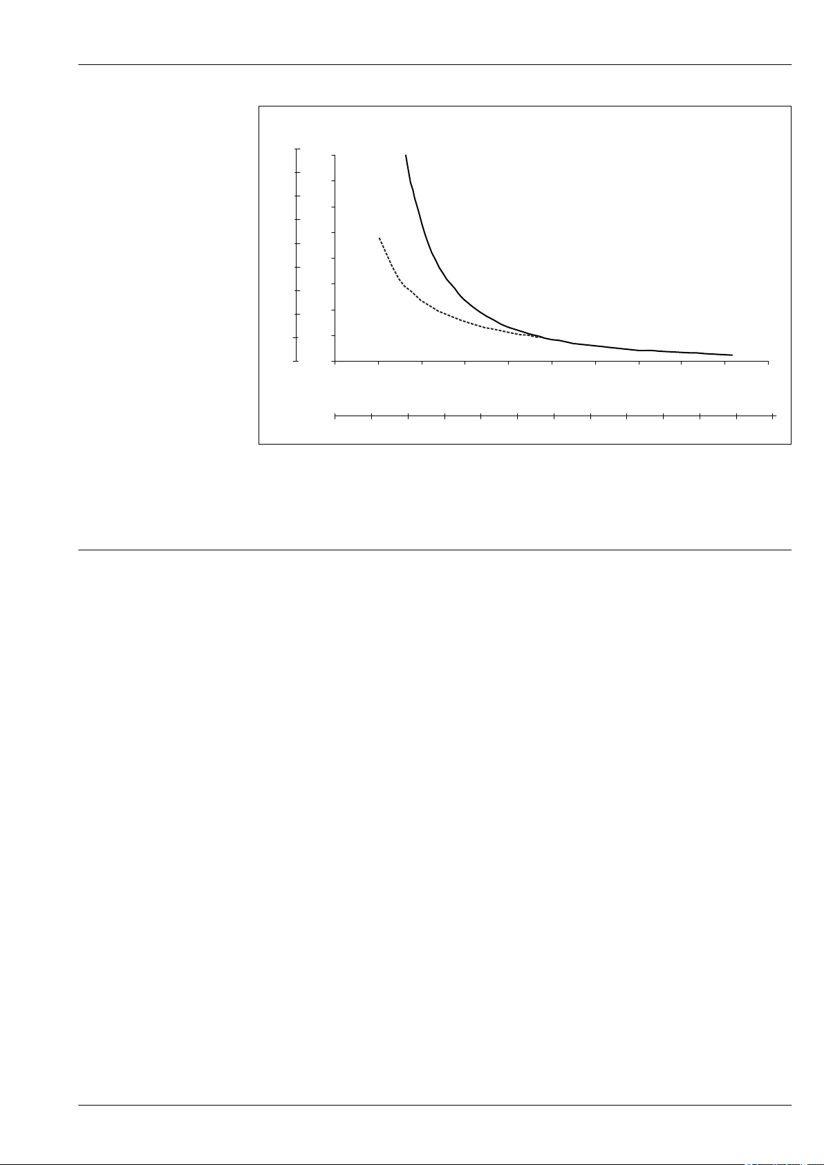
Example of the permitted flow velocity depending on the immersion length and process
medium
The highest flow velocity tolerated by the thermometer diminishes with increasing insert immersion
length exposed to the stream of the fluid. In addition it is dependent on the diameter of the
thermometer tip, on the kind of measuring medium, on the process temperature and on the process
pressure. The following figures exemplify the maximum permitted flow velocities in water and
superheated steam at a process pressure of 40 bar (580 PSI).
12 Endress+Hauser
Page 13
iTHERM TM402
v (ft/s)
0 1 2 3 4 5 7 8 9 10
11
L (in)
6
12
0
5
10
15
20
25
30
35
40
0 30 60 90 120 150 180 210 240 270 300
L (mm)
v (m/s)
0
15
30
45
60
75
90
105
B
A
A0008065
5 Permitted flow velocities, thermowell diameter 6.35 mm (¼ in)
A Medium water at T = 50 °C (122 °F)
B Medium superheated steam at T = 400 °C (752 °F)
L Immersion length exposed to flow
v Flow velocity
Medium - state of
Gaseous or liquid (also with high viscosity, e.g. yogurt).
aggregation
Endress+Hauser 13
Page 14
Mechanical construction
1 2 3 4 5
6.35
( )¼
U
T
U
T
U
T
6.35
( )¼
( )¼
6.35
3 (0.12)
8 (0.32)
8 (0.32)
8 (0.32)
( )¼
6.35
!4.76
(3/16)
8 (0.32)
U
T
9.53
(3/8)
!4.76
(3/16)
iTHERM TM402
Design, dimensions
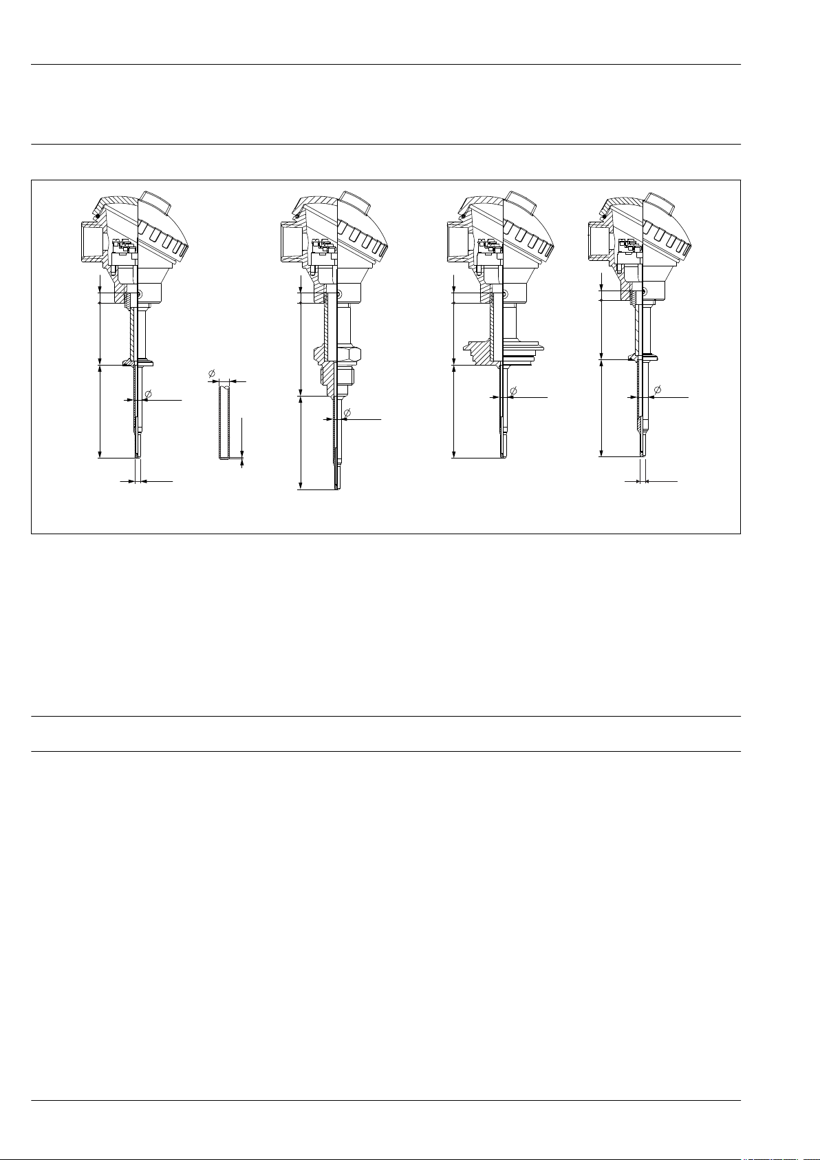
All dimensions in mm (in).
A0034462
1 Thermometer with clamp process connection and 6.35 mm (¹⁄₄ in) thermowell with reduced tip
4.76 mm (³⁄₁₆ in)
2 Optional for all thermometers with 6.35 mm (¹⁄₄ in) thermowell: straight tip shape
3 Thermometer with ISO228 process connection and 6.35 mm (¹⁄₄ in) thermowell with reduced tip
4.76 mm (³⁄₁₆ in)
4 Thermometer with Varivent process connection and 6.35 mm (¹⁄₄ in) thermowell with reduced
4.76 mm (³⁄₁₆ in)
5 Thermometer with clamp process connection and 9.53 mm (³⁄₈ in) thermowell with reduced tip
4.76 mm (³⁄₁₆ in)
T Length of extension neck
U Immersion length
Weight
Material
Depending on the configuration
The temperatures for continuous operation specified in the following table are only intended as
reference values for use of the various materials in air and without any significant compressive load.
14 Endress+Hauser
Page 15
iTHERM TM402
107.5 (4.23)
68.5 (2.7)
28
(1.1)
78 (3.1)
15.5 (0.6)
The maximum operating temperatures can be reduced considerably in cases where abnormal
conditions such as high mechanical load occur or in aggressive media.
Recommended max.
Designation
AISI 316L 650 °C (1 202 °F)
1) Can be used to a limited extent up to 800 °C (1472 °F) for low compressive loads and in non-corrosive
media. Contact your Endress+Hauser sales team for further information.
temperature for
continuous use in air
1)
Properties
• Austenitic, stainless steel
• High corrosion resistance in general
• Particularly high corrosion resistance in chlorinebased and acidic, non-oxidizing atmospheres
through the addition of molybdenum (e.g.
phosphoric and sulfuric acids, acetic and tartaric
acids with a low concentration)
• Increased resistance to intergranular corrosion and
pitting
• The wetted part from a 316L or 1.4435+316L
thermowell withstand a passivation process with a
3% sulphuric acid
Surface roughness
Terminal heads
Values for wetted surfaces:
Standard surface Ra ≤ 0.76 µm (30 µin)
Finely honed surface
1) Not compliant with ASME BPE
1)
Ra ≤ 0.38 µm (15 µin)
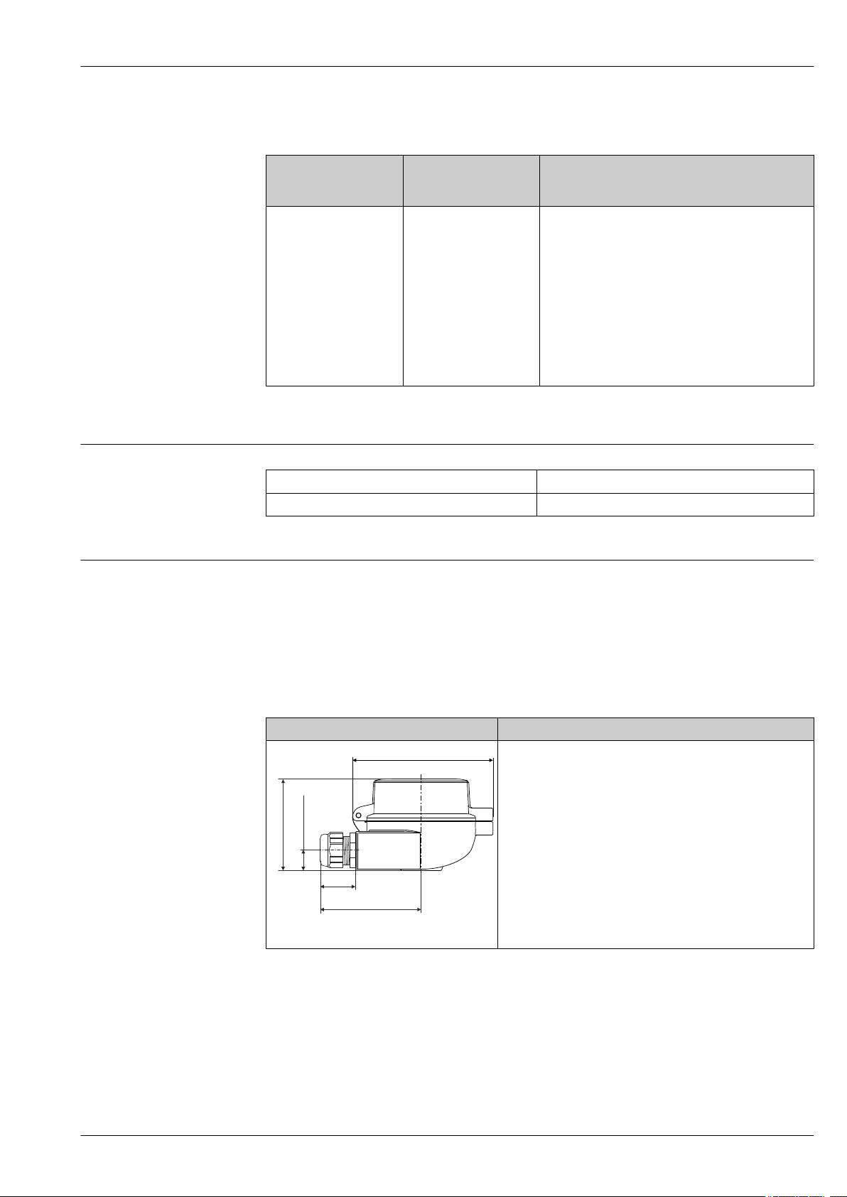
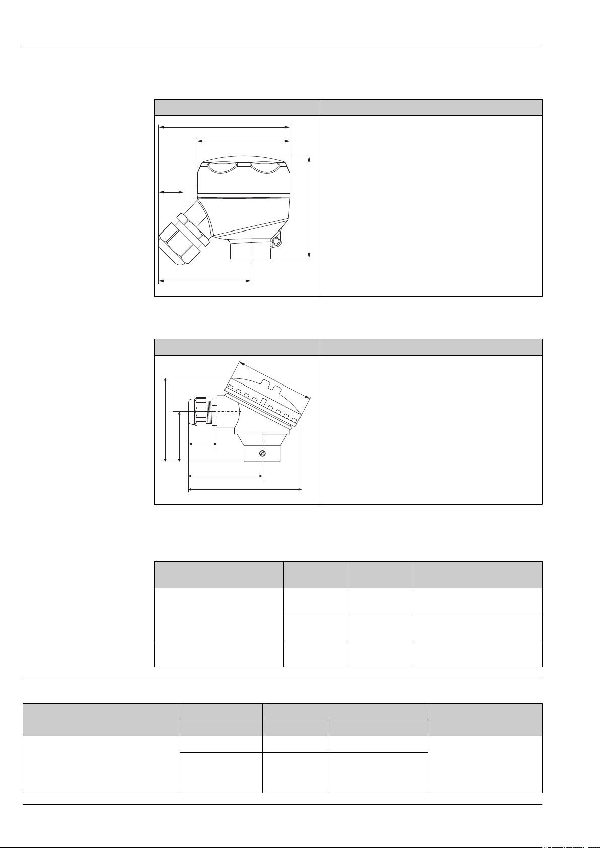
All terminal heads have an internal shape and size in accordance with DIN EN 50446, flat face and a
thermometer connection with a ½" NPT or M24x1.5 thread. All dimensions in mm (in). The sample
cable glands in the diagrams correspond to M20x1.5 connections with non-Ex polyamide cable
glands. Specifications without head transmitter installed. For ambient temperatures with head
transmitter installed, see the 'Environment' section. → 11
As a special feature, Endress+Hauser offers terminal heads with optimized terminal accessibility for
easy installation and maintenance.
TA30A Specification
• Protection class:
– IP66/68 (NEMA Type 4x encl.)
– For ATEX: IP66/67
• Temperature: –50 to +150 °C (–58 to +302 °F) without cable
gland
• Material: aluminum, polyester powder coated
Seals: silicone
• Threaded cable entry: G ½", ½" NPT and M20x1.5;
• Protection armature connection: ½" NPT, M24x1.5
• Head color: blue, RAL 5012
• Cap color: gray, RAL 7035
• Weight: 330 g (11.64 oz)
A0009820
• Ground terminal, internal and external
• Available in conjunction with 3-A marked sensors
Endress+Hauser 15
Page 16
71 (2.8)
64 (2.52)
64 (2.52)
96 (3.8)
25
(1)
122 (4.8)
28
(1.1)
78 (3.1)
50 (1.97)
87 (3.43)
81.7 (3.22)
TA30R Specification
• Degree of protection - standard version: IP69K (NEMA Type
4x encl.)
• Temperature: –50 to +130 °C (–58 to +266 °F) without cable
gland
• Material: stainless steel 316L, abrasive-blasted or handpolished
Seals: EPDM
• Cable entry thread ½" NPT and M20x1.5
• Weight: 360 g (12.7 oz)
• Protection armature connection: M24x1.5 or ½" NPT
• Ground terminal: internal in standard version; external
terminal optionally available
• Available in conjunction with 3-A marked sensors
A0018914
iTHERM TM402
TA30S Specification
• Degree of protection: IP65 (NEMA Type 4x encl.)
• Temperature: –40 to +85 °C (–40 to +185 °F) without cable
gland
• Material: polypropylene (PP), FDA-compliant, seals: O-ring
EPDM
• Cable entry thread: ¾" NPT (with adapter for ½" NPT),
M20x1.5
• Protective assembly connection: ½" NPT
• Color: white
• Weight: approx. 100 g (3.5 oz)
• Ground terminal: only internal via auxiliary terminal
• Available in conjunction with 3-A marked sensors
A0017146
Cable glands and fieldbus connectors
Type
Cable gland, polyamide
Fieldbus connector (M12, 4-pin)
Suitable for
cable entry
½" NPT, ¾" NPT,
M20x1.5
½" NPT,
M20x1.5
½" NPT,
M20x1.5
Degree of
protection
IP68 –40 to +100 °C (–40 to +212 °F)
IP69K –20 to +95 °C (–4 to +203 °F)
IP67, NEMA
Type 6
Temperature range
–40 to +105 °C (–40 to +221 °F)
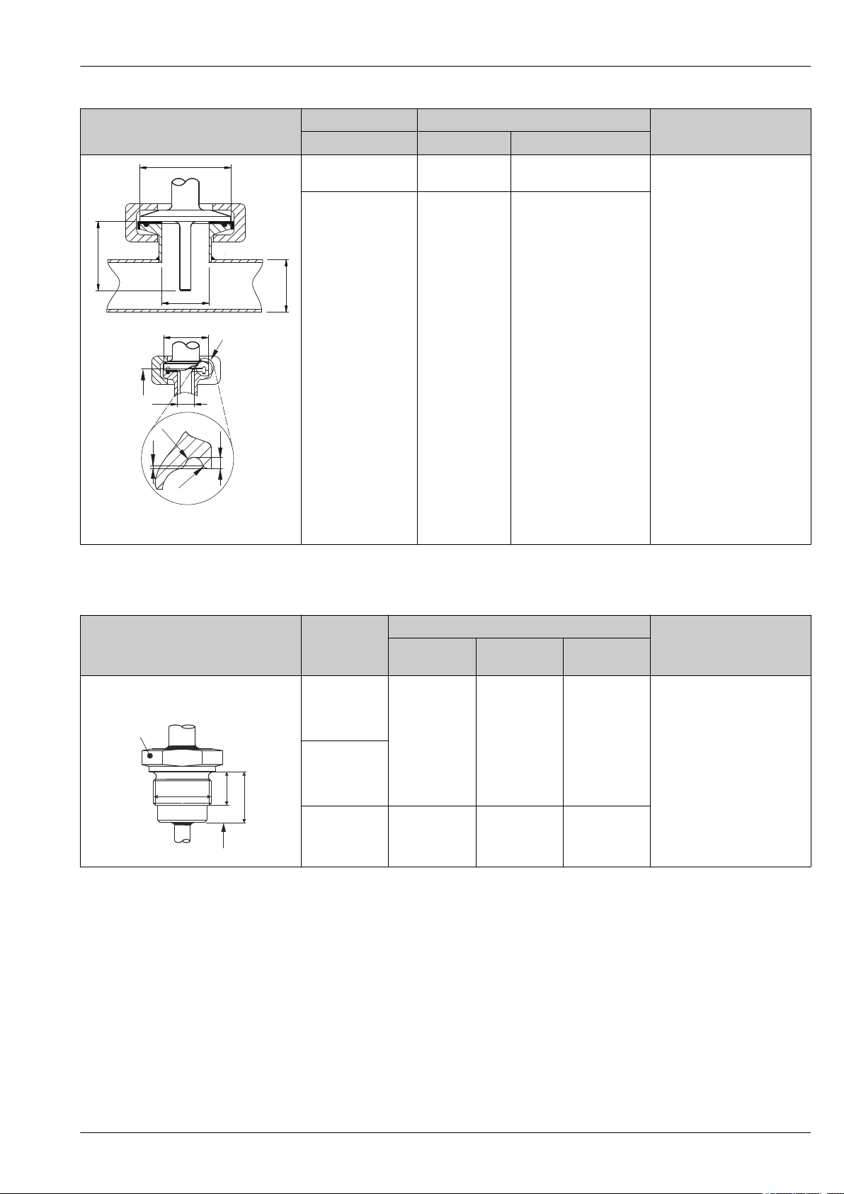
Process connections
All dimensions in mm (in).
Version Dimensions
Type
Clamp according to ASME BPE or ISO 2852 Tri-clamp ¾" (DN18) 25 mm (0.98 in) - • P
Clamp ISO 2852 ½"
1)
d:
(DN12 - 21.3)
D a
34 mm (1.34 in) 16 to 25.3 mm
(0.63 to 0.99 in)
16 Endress+Hauser
Technical properties
= 16 bar (232 psi),
max.
depends on clamp ring and
suitable seal
• With 3-A symbol
• ASME BPE compliance
Page 17
iTHERM TM402
!D
U
!d
!a
!d
U
!D
R1.2
R0.8
0.4
1.6
A
A: Tri-clamp
U
L1
1
G
A
Type
A0033985
A Different seal geometries for Tri-clamp
Version Dimensions
1)
d:
Tri-clamp 1" - 1½"
(DN25 - 38)
Tri-clamp 2" (DN40 -
D a
50.5 mm
(1.99 in)
64 mm (2.52 in) 44.8 to 55.8 mm
51)
29 to 42.4 mm
(1.14 to 1.67 in)
(1.76 to 2.2 in)
Technical properties
• P
= 16 bar (232 psi),
max.
depends on clamp ring and
suitable seal
• With 3-A symbol and
EHEDG certification (sealing
according to EHEDG position
paper, DN25, DN40,
DN63,5)
• ASME BPE compliance
2)
1) Pipes in accordance with ISO 2037 and BS 4825 Part 1
2) Not for clamp ½"
Dimensions
Type Version G
L1 thread
A 1 (SW/AF)
Technical properties
length
Thread according to ISO 228 (for
Liquiphant weld-in adapter)
G¾" for FTL20
adapter
G¾" for FTL50
adapter
16 mm
(0.63 in)
25.5 mm (1 in) 32
• P
= 25 bar (362 psi) at
max.
max. 150 °C (302 °F)
• P
= 40 bar (580 psi) at
max.
max. 100 °C (212 °F)
• In connection with
FTL31/33/50 adapter
3-A symbol and EHEDG
certification
• ASME BPE compliance
• Minimum extension neck
lengths: ≥ 76.2 mm (3 in)
A0009572
G1" for FTL50
adapter
18.6 mm
(0.73 in)
29.5 mm
(1.16 in)
41
Endress+Hauser 17
Page 18
iTHERM TM402
U
!D
!B
!A
h
U
!D
!i
!a
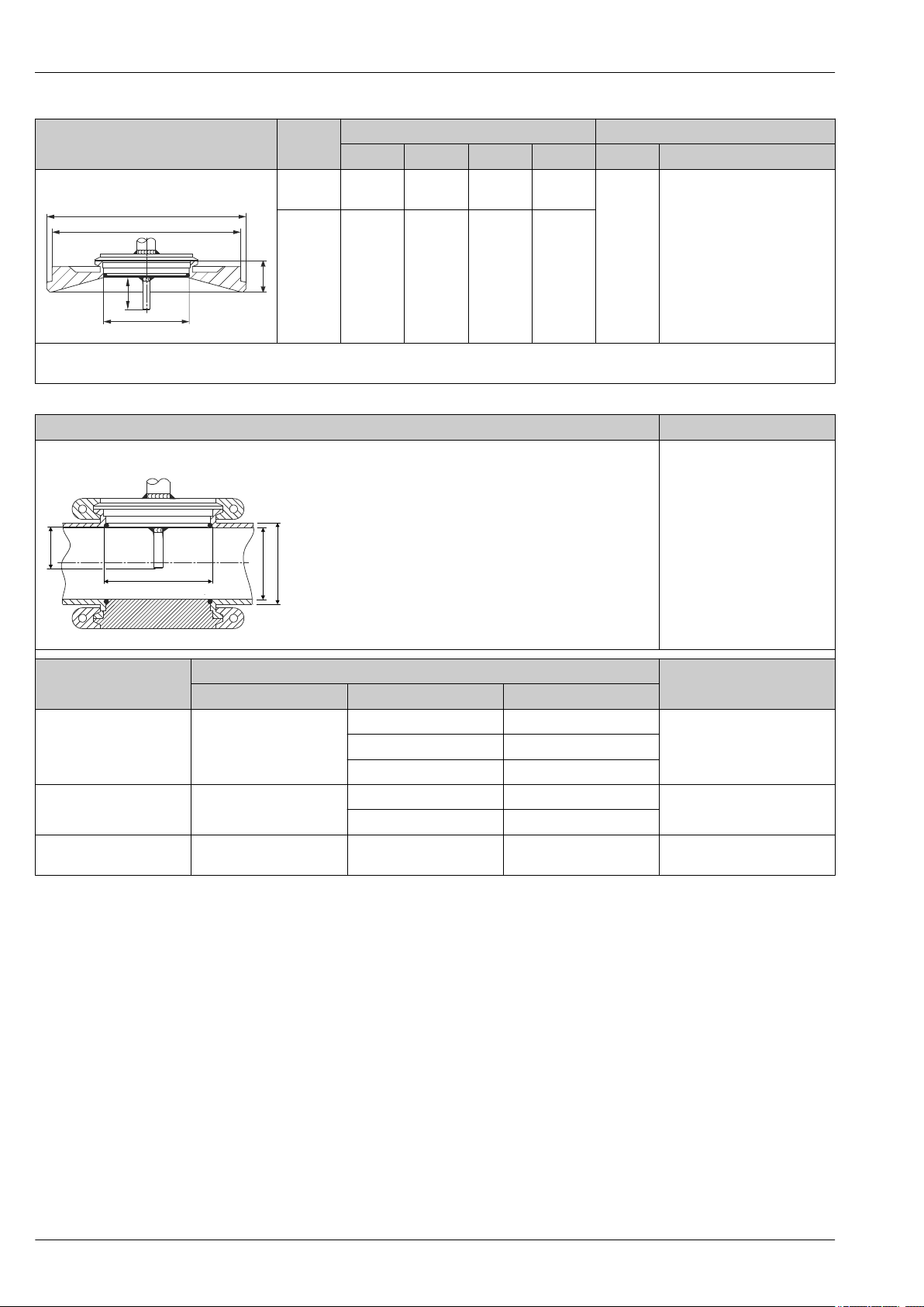
Type Version
Dimensions Technical properties
D A B h P
®
Varivent
A0021307
The VARINLINE® housing connection flange is suitable for weld-in into the conical or torispherical head in tanks or containers with a small
diameter (≤ 1.6 m (5.25 ft)) and up to a wall thickness of 8 mm (0.31 in).
Type F 50 mm
(1.97 in)
Type N 68 mm
(2.67 in)
145 mm
(5.71 in)
165 mm
(6.5 in)
135 mm
(5.31 in)
155 mm
(6.1 in)
24 mm
(0.95 in)
24.5 mm
(0.96 in)
max.
10 bar
(145 psi)
• With 3-A symbol and
EHEDG certification
• ASME BPE compliance
Type Technical properties
Varivent® for VARINLINE® housing for installation in pipes
• With 3-A symbol and
EHEDG certification
• ASME BPE compliance
Version
Type N, according to DIN
11866, series C
Type N, according to DIN
11866, series C
Type F, according to DIN
11866, series C
Dimensions
D i a
OD 1½": 34.9 mm (1.37 in) OD 1½": 38.1 mm (1.5 in)
68 mm (2.67 in)
OD 2": 47.2 mm (1.86 in) OD 2": 50.8 mm (2 in)
OD 2½": 60.2 mm (2.37 in) OD 2½": 63.5 mm (2.5 in)
OD 3": 73 mm (2.87 in) OD 3": 76.2 mm (3 in)
68 mm (2.67 in)
OD 4": 97.6 mm (3.84 in) OD 4": 101.6 mm (4 in)
50 mm (1.97 in)
OD 1": 22.2 mm (0.87 in) OD 1": 25.4 mm (1 in)
A0009564
OD 1½" to OD 2½":
16 bar (232 psi)
OD 3" to OD 4": 10 bar (145 psi)
16 bar (232 psi)
P
max.
18 Endress+Hauser
Page 19

iTHERM TM402
Certificates and approvals
CE mark
Hygiene standard
Other standards and guidelines
Parts in contact with the medium
The product meets the requirements of the harmonized European standards. As such, it complies
with the legal specifications of the EC directives. The manufacturer confirms successful testing of the
product by affixing to it the CE-mark.
• EHEDG certification, type EL - CLASS I. Permitted process connections in accordance with EHEDG,
see 'Process connections' section → 16
• 3-A authorization no. 1144, 3-A sanitary standard 74-06. Permitted process connections in
accordance with 3-A, see 'Process connections' section → 16
• ASME BPE 2009, certificate of conformity can be ordered for indicated options
• IEC 60529: Degrees of protection provided by enclosures (IP code)
• IEC 61010-1: Safety requirements for electrical equipment for measurement, control and
laboratory use
• IEC 60751: Industrial platinum resistance thermometers
• ASTM E 1137/E1137M-2008: Standard Specification for Industrial Platinum Resistance
Thermometers
• EN 50281-1-1: Electrical apparatus protected by enclosures
• DIN EN 50446: Terminal heads
• IEC 61326-1: Electromagnetic compatibility (electrical equipment for measurement, control and
laboratory use - EMC requirements)
Parts of the thermometer in contact with the medium comply with the following European
regulations:
• (EC) No. 1935/2004, Article 3, paragraph 1, Articles 5 and 17 on materials and articles intended
to come into contact with food.
• (EC) No. 2023/2006 on good manufacturing practice for materials and articles intended to come
into contact with food.
• (EC) No. 10/2011 on plastic materials and articles intended to come into contact with food.
• FDA-compliant
• All product contact surfaces are produced without animal derived ingredients (ADI/TSE)
CRN approval
Surface purity
Material resistance
Material certification
Calibration
The CRN approval is only available for certain options of protection tubes. These will be marked and
shown during the configuration of this device.
Free from oil and grease, optional
Material resistance - including housing - to the following cleaning agents/disinfectants from the
company Ecolab: P3-topax 66, P3-topactive 200, P3-topactive 500 and P3-topactive OKTO as well as
demineralized water.
The material certificate 3.1 (according to standard EN 10204) can be requested separately.
The "Factory calibration" is carried out according to an internal procedure in a laboratory of Endress
+Hauser accredited by the European Accreditation Organization (EA) to ISO/IEC 17025. A
calibration which is performed according to EA guidelines (SIT/Accredia) or (DKD/DAkkS) may be
requested separately. The calibration is performed on the replaceable insert of the thermometer. In
the case of thermometers without a replaceable insert, the entire thermometer - from the process
connection to the tip of the thermometer - is calibrated.
Endress+Hauser 19
Page 20

iTHERM TM402
Ordering information
Detailed ordering information is available from the following sources:
• In the Product Configurator on the Endress+Hauser website: www.endress.com -> Click "Corporate"
-> Select your country -> Click "Products" -> Select the product using the filters and search field ->
Open product page -> The "Configure" button to the right of the product image opens the Product
Configurator.
• From your Endress+Hauser Sales Center: www.addresses.endress.com
Product Configurator - the tool for individual product configuration
• Up-to-the-minute configuration data
• Depending on the device: Direct input of measuring point-specific information such as
measuring range or operating language
• Automatic verification of exclusion criteria
• Automatic creation of the order code and its breakdown in PDF or Excel output format
• Ability to order directly in the Endress+Hauser Online Shop
20 Endress+Hauser
Page 21
iTHERM TM402
Accessories
Various accessories, which can be ordered with the device or subsequently from Endress+Hauser, are
available for the device. Detailed information on the order code in question is available from your
local Endress+Hauser sales center or on the product page of the Endress+Hauser website:
www.endress.com.
Device-specific accessories
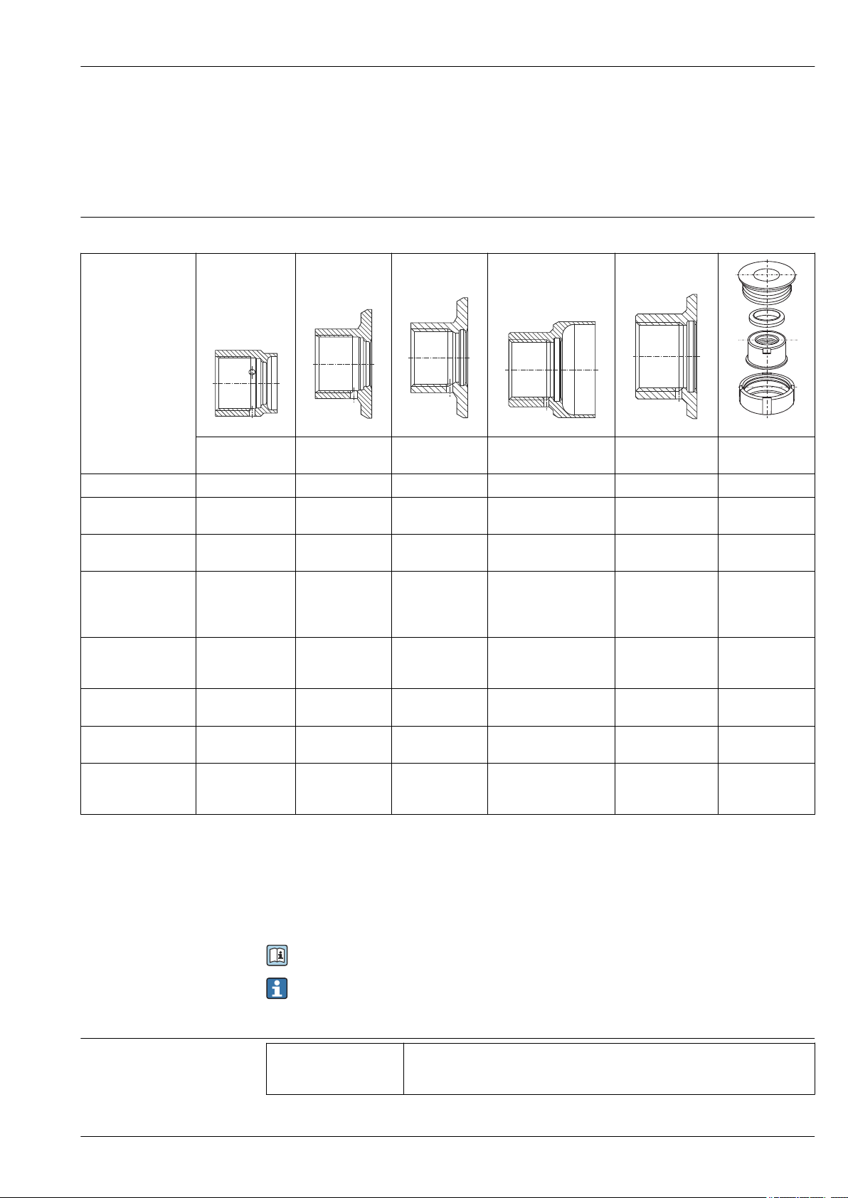
Weld-in adapter
A0008246 A0008251 A0008256 A0011924 A0008248 A0008253
G ¾", d=29 for
pipe-mounting
G ¾", d=50 for
vessel-mounting
G ¾", d=55 with
flange
G 1", d=53 without
flange
G 1", d=60 with
flange
G 1" adjustable
Material 316L (1.4435) 316L (1.4435) 316L (1.4435) 316L (1.4435) 316L (1.4435) 316L (1.4435)
Roughness μm (μin)
process side
Order number weldin adapter
≤1.5 (59.1) ≤0.8 (31.5) ≤0.8 (31.5) ≤0.8 (31.5) ≤0.8 (31.5) ≤0.8 (31.5)
71258357 71258355 52001052 71258358 52001051
1)
52001221
Order number weldin adapter with
inspection
certificate
3) 4)
Order number for seal
replacement (5
5)
pieces)
Order number
welding dummy
Order number blind
6)
plug
6)
52028295 52018765 52011897 71093129 52011896
Silicone O-ring
52021717
Silicone O-ring
52021717
Silicone O-ring
52014473
Silicone O-ring
52014472
Silicone O-ring
52014472
71174959 71174959 71168889 71166879 71166879 71181945
71167850 71167850 71177193 71173810 71173810 71166366
1)
52011898
Silicone profile
gasket
52014424
Order number blind
plug with inspection
certificate
4) 6)
- - 71190074 71167291 71167291 71196853
2)
2)
1) Replace the weld-in adapter with order number 917969-1000.
2) Replace the weld-in adapter with order number 215159-0000.
3) AD2000: The material 316L (in contact with process) corresponds to AD2000 – W0/W2.
4) Inspection certificate EN10204-3.1 material
5) One seal is included in scope of delivery.
6) TSP modification number. Can be ordered only FTSP, PTSP or NTSP.
For more information on the weld-in adapters, see Technical Information (TI00426F).
Maximum process pressure for the weld-in adapters:
• 25 bar (362 PSI) at maximum 150 °C (302 °F)
• 40 bar (580 PSI) at maximum 100 °C (212 °F)
Communication-specific accessories
Configuration kit TXU10 Configuration kit for PC-programmable transmitter with setup software and
interface cable for PC with USB port
Order code: TXU10-xx
Endress+Hauser 21
Page 22

iTHERM TM402
Commubox FXA195
HART
Commubox FXA291 Connects Endress+Hauser field devices with a CDI interface (= Endress+Hauser
Wireless HART adapter
SWA70
Fieldgate FXA42 Gateway for remote monitoring of connected 4 to 20 mA analog as well as digital
Field Xpert SFX350 Field Xpert SFX350 is a mobile computer for commissioning and maintenance. It
Field Xpert SFX370 Field Xpert is an industrial PDA with integrated touchscreen for commissioning
For intrinsically safe HART communication with FieldCare via the USB interface.
For details, see Technical Information TI00404F
Common Data Interface) and the USB port of a computer or laptop.
For details, see Technical Information TI00405C
Is used for the wireless connection of field devices.
The WirelessHART adapter can be easily integrated into field devices and existing
infrastructures, offers data protection and transmission safety and can be operated
in parallel with other wireless networks with minimum cabling complexity.
For details, see Operating Instructions BA00061S
field devices.
For details, see Technical Information TI01297S and Brief Operating
Instructions KA01246S
enables efficient device configuration and diagnostics for HART and FOUNDATION
Fieldbus devices in the non-Ex area.
For details, see Operating Instructions BA01202S
and maintaining field devices in explosion hazardous and safe areas. It allows
efficient configuration of FOUNDATION fieldbus, HART 5/6/7 and WirelessHART
devices via Bluetooth and/or Wifi interfaces.
For details, see Technical Information TI01114S and Operating Instructions
BA01202S
Service-specific accessories
Field Xpert SMT70 The Field Xpert SMT70 is an out-of-the box tablet PC for universal device
configuration that has pre-installed devices libraries. It supports devices with
protocols such as HART, PROFIBUS DP/PA, FOUNDATION Fieldbus, Modbus, and
Endress+Hauser service protocols.
For details, see Technical Information TI01342S
Accessories Description
Applicator Software for selecting and sizing Endress+Hauser measuring devices:
• Calculation of all the necessary data for identifying the optimum measuring
device: e.g. pressure loss, accuracy or process connections.
• Graphic illustration of the calculation results
Administration, documentation and access to all project-related data and
parameters over the entire life cycle of a project.
Applicator is available:
• Via the Internet: https://portal.endress.com/webapp/applicator
• On CD-ROM for local PC installation.
22 Endress+Hauser
Page 23

iTHERM TM402
Configurator Product Configurator - the tool for individual product configuration
• Up-to-the-minute configuration data
• Depending on the device: Direct input of measuring point-specific information
such as measuring range or operating language
• Automatic verification of exclusion criteria
• Automatic creation of the order code and its breakdown in PDF or Excel output
format
• Ability to order directly in the Endress+Hauser Online Shop
The Configurator is available on the Endress+Hauser website: www.endress.com ->
Click "Corporate" -> Select your country -> Click "Products" -> Select the product
using the filters and the search field -> Open the product page -> The "Configure"
button to the right of the product image opens the Product Configurator.
W@M Life cycle management for your plant
W@M supports you with a wide range of software applications over the entire
process: from planning and procurement, to the installation, commissioning and
operation of the measuring devices. All the relevant device information, such as
the device status, spare parts and device-specific documentation, is available for
every device over the entire life cycle.
The application already contains the data of your Endress+Hauser device. Endress
+Hauser also takes care of maintaining and updating the data records.
W@M is available:
• Via the Internet: www.endress.com/lifecyclemanagement
• On CD-ROM for local PC installation.
System components
FieldCare SFE500 FDT-based plant asset management tool from Endress+Hauser.
It can configure all smart field units in your system and helps you manage them. By
using the status information, it is also a simple but effective way of checking their
status and condition.
For details, see Operating Instructions BA00027S and BA00065S
DeviceCare SFE100 Configuration tool for devices via fieldbus protocols and Endress+Hauser service
protocols.
DeviceCare is the tool developed by Endress+Hauser for the configuration of
Endress+Hauser devices. All smart devices in a plant can be configured via a pointto-point or point-to-bus connection. The user-friendly menus enable transparent
and intuitive access to the field devices.
For details, see Operating Instructions BA00027S
Accessories Description
Display RIA15 It is integrated in the 4 to 20 mA or HART® loop and transmits the measuring
signal or HART® process variables in digital form. The process display unit does not
require an external power supply. It is powered directly from the current loop.
For details, see the "Technical Information" document TI01043K
Memograph M, RSG45 Advanced Data Manager with tamper-proof data storage and access (FDA 21 CFR
11) HART® gateway functionality; Up to 40 HART® devices connected at a time
Communication capabilities: Modbus, Profibus DP, PROFINET, EtherNet/IP.
For details, see the "Technical Information" document TI01180R
Active barrier RN221N Active barrier with power supply for safe separation of 4-20 mA standard signal
circuits. Offers bidirectional HART transmission.
For details, see "Technical Information" TI00073R and Operating Instructions
BA00202R
Endress+Hauser 23
Page 24

iTHERM TM402
Power supply RNS221 Supply unit for powering two 2-wire measuring devices solely in the non-Ex area.
Bidirectional communication is possible via the HART communication jacks.
For details, see "Technical Information" TI00081R and Brief Operating
Instructions KA00110R
Documentation
Technical information:
Resistance thermometer for hygienic and aseptic applications iTHERM TM402: TI01349T
Modular resistance thermometer for hygienic and aseptic applications iTHERM TM412:
TI01348T
Insert for thermometer installation iTHERM TS212: TI01336T
Thermometer protection tube for hygienic and aseptic applications iTHERM TT412: TI01350T
Process Indicator RIA15: TI01043K
Advanced Data Manager Memograph M RSG45: TI01180R
Field Data Manager Software MS20, MS21: TI01022R
iTEMP temperature head transmitter:
TMT80, PC-programmable, single-channel, RTD and TC: TI00153R
TMT180, PC-programmable, single-channel, Pt100: TI00088R
TMT181, PC-programmable, single-channel, RTD, TC, Ω, mV: TI00070R
HART® TMT182, single-channel, RTD, TC, Ω, mV: TI00078R
24 Endress+Hauser
Page 25

Page 26

Page 27

Page 28

www.addresses.endress.com
 Loading...